Embed Size (px)
Citation preview

Repair Manual Free Standing Gas Skillets
Models SGM-X SGL-X

OPERATING CONTROLS AND INDICATORS
For your better understanding and confidence, the following explanation of the control system used on these skillets is offered.
Item No. Description Function
Gas Control Valve 13 (Skillet Bottom Dwg.)
Controls main gas supply to the skillet.
Pilot Light When illuminated, the lower pilot light indicates (Electrical electrical power is on to the skillet and the upper pilot
2
Components Dwg.) light indicates the main gas burners are on.
Thermostat Control Knob This control knob allows the operator to select various (Electrical
4
Components Dwg.) heat increments for operating the skillet
On/Off Toggle Switch
(Electrical
7
Components Dwg.)
Controls electrical power to the skillet
Timer Control Knob This knob controls the bell timer and allows the (Electrical operator to select a time interval after which a bell
9
Components Dwg.) will sound.
Tilt Switch When activated this switch will raise or lower the (Electrical
15
Components Dwg.) skillet pan.
Hand Wheel (Hydraulic Lift
13, 17
Mechanism Dwg.)
Turn counter-clockwise to raise skillet pan.
Push Button (Hydraulic Lift
12, 16
Mechanism Dwg.)
Press to allow skillet pan to lower.
Micro Switch Protective switch to prevent burners from igniting
(Electric Jack
10
Assembly Dwg.) white skillet pan is in a raised position.
Micro Switch Protective switch to prevent burners from igniting
(Hydraulic Jack
27
Assembly Dwg.) write skillet pan is in a raised position.
1

PARTS LIST - SKILLET BOTTOM
Item No. Part No. Description Qty. 1 SK50502 Burner 6,8 2 SK50520 Zip Tube (SGL, SGM-30-X) 1
SK50521 Zip Tube (SGL, SGM-40-X) 1 3 SK50553 Bracket, Pilot Mounting 1 4 FA10360 Screw. 10-32 x 1/4" 2 5 SK50363 Orifice, Zip Tube, Natural Gas 1
(0-2000 Ft Elev. #61 Drill)
SK50669 Orifice, Zip Tube, Natural Gas 1
(2000-4000 Ft Elev. #62 Drill)
SK50671 Orifice, Zip Tube, Natural Gas 1
(4000-6000 Ft Elev. #63 Drill)
SK50364 Orifice, Zip Tube, L.P. 1
(0-2000 Ft Elev. #72 Drill)
SK50670 Orifice, Zip Tube, L.P. 1
(2000-4000 Ft Elev. #73 Drill)
SK50672 Orifice, Zip Tube, L.P. 1
(4000-6000 Ft Elev. #74 Drill)
2

6 SK50503 Orifice, Burner, Natural Gas 6,8
(0-2000 Ft. Elev. #52 Drill)
SK50505 Orifice, Burner, Natural Gas 6,8
(2000-4000 Ft. Elev. #1/16 Drill)
SK50507 Orifice, Burner, Natural Gas 6,8
(4000-6000 Ft Elev. #53 Drill)
SK50504 Orifice, Burner, L.P. 6,8
(0-2000 Ft. Elev. #57 Drill)
SK50506 Orifice, Burner, L.P. 6,8
(2000-4000 Ft. Elev. #58 Drill)
SK50508 Orifice, Burner, L.P. 6,8
(4000-6000 Ft. Elev. #59 Drill) 7 SK00192 Manifold, Burner (SQL SGM-30-X) 1
SK00193 Manifold, Burner (SGL SGM-40-X) 1 8 KE51111 Pilot name Sensor 1
(Thermopile Type) (Manual Ignition)
KE51159 Pilot Flame Sensor 1
(Mercury Vapour Type) (Spark Ignition) 9 KE01016 Ignition Electrode (Spark Ignition) 1
10 KE51114 Pilot Burner 1 11 KE51115 Holder, Pilot Flame Sensor 1
(Manual Ignition) 12 KE51116 Orifice, Pilot, Natural Gas (.020") 1
KE51162 Orifice, Pilot, L.P. (.0145") 1 13 KE51155 Combination Gas Control Valve, Natural 1
Gas, 24 VAC (Spark Ignition)
KE51163 Combination Gas Control Valve, L.P., 1
24 VAC (Spark Ignition)
SK50608 Combination Gas Control Valve, Natural 1
Gas, 24 VAC (Manual Ignition)
SE00043 Combination Gas Control Valve, L.P., 1
24 VAC (Manual Ignition)
KE51110 Combination Gas Control Valve, Natural 1
Gas, 120 VAC (Manual Ignition)
KE51161 Combination Gas Control Valve, L.P., 1
120 VAC (Manual Ignition) 14 SK50249 Heat Spreader (R.H. End Piece) 1
SK50531 Heat Spreader (L.H. End Piece) 1
SK50532 Heat Spreader (with Thermostat cut-out) 1
SK50213 Heat Spreader (Plain) 3,5 15 SK50416 Washer. Spherical 28,36 16 FA21024 Nut, 5/16-18 28,36 Use only replacement parts which are factory supplied as to preserve the certification of Underwriters Laboratories, American Gas Association, Canadian Standards Association or Canadian Gas Association (as applicable). The use of other than factory supplied replacement parts will void the warranty.
3

ELECTRICAL COMPONENTS
4
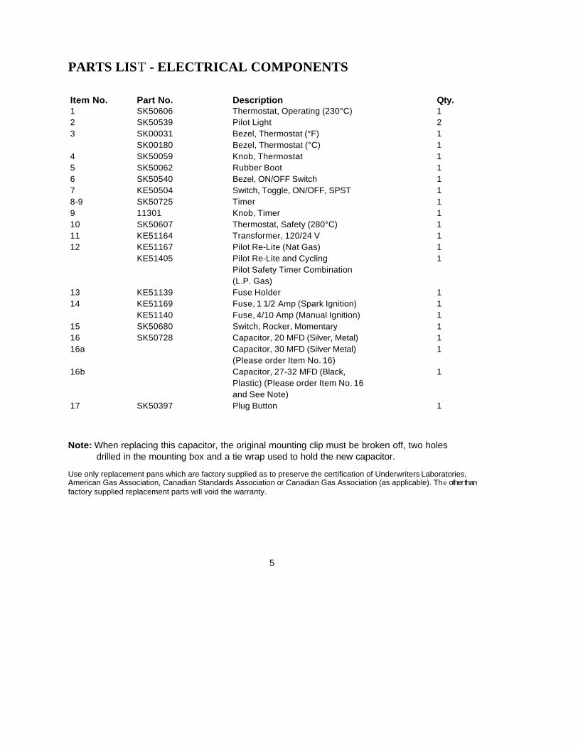
PARTS LIST - ELECTRICAL COMPONENTS
Item No. Part No. Description Qty. 1 SK50606 Thermostat, Operating (230°C) 1 2 SK50539 Pilot Light 2 3 SK00031 Bezel, Thermostat (°F) 1
SK00180 Bezel, Thermostat (°C) 1 4 SK50059 Knob, Thermostat 1 5 SK50062 Rubber Boot 1 6 SK50540 Bezel, ON/OFF Switch 1 7 KE50504 Switch, Toggle, ON/OFF, SPST 1 8-9 SK50725 Timer 1 9 11301 Knob, Timer 1 10 SK50607 Thermostat, Safety (280°C) 1 11 KE51164 Transformer, 120/24 V 1 12 KE51167 Pilot Re-Lite (Nat Gas) 1
KE51405 Pilot Re-Lite and Cycling 1
Pilot Safety Timer Combination
(L.P. Gas) 13 KE51139 Fuse Holder 1
14 KE51169 Fuse, 1 1/2 Amp (Spark Ignition) 1
KE51140 Fuse, 4/10 Amp (Manual Ignition) 1 15 SK50680 Switch, Rocker, Momentary 1 16 SK50728 Capacitor, 20 MFD (Silver, Metal) 1 16a
Capacitor, 30 MFD (Silver Metal) 1
(Please order Item No. 16) 16b
Capacitor, 27-32 MFD (Black, 1
Plastic) (Please order Item No. 16
and See Note) 17 SK50397 Plug Button 1
Note: When replacing this capacitor, the original mounting clip must be broken off, two holes drilled in the mounting box and a tie wrap used to hold the new capacitor.
Use only replacement pans which are factory supplied as to preserve the certification of Underwriters Laboratories, American Gas Association, Canadian Standards Association or Canadian Gas Association (as applicable). The other than factory supplied replacement parts will void the warranty.
5

PARTS LIST - HYDRAULIC LIFT MECHANISM (PRIOR TO APRIL 1,1988)
Item No. Part No. Description Qty. 1 FI05048 Tee 1 2 FI05132 Ballcheck Connector 1 3 SK50557 Plug, 3/4" NPT 1 4 SK00191 Oil Tank 1 5 SK50715 Motor Oil, SAE 30 1L/1 Qt 6 FI00236 Plug, 1/4" NPT 1 7 FI00350 Reducer Bushing 1 8 FI05133 Pipe 1 9 SK50604 Bracket, Relief Valve 1 10 SK50603 Relief Valve 1 11 FA19060 Set Screw, #8-32 x 1/8" 1 12 SK00241 Push Button 1 13-14 KE00508 Hand Wheel 1 14 FA19501 Set Screw, 3/8- 16 x 3/8" 1 15 SK50556 Bushing, Hand Wheel 1 16 SK50602 Hydraulic Pump 1 17 FA31009 Lockwasher, 5/16 2 18 FA20010 Hex Nut, 5/16-18 2
Use only replacement parts which are factory supplied as to preserve the certification of Underwriters Laboratories, American Gas Association, Canadian Standards Association or Canadian Gas Association (as applicable). The use of other than factory supplied replacement parts will void the warranty.
6

PARTS LIST - HYDRAULIC LIFT MECHANISM (AFTER APRIL 1,1988)
Item No. Part No. Description Qty. 1 SK00191 Oil Tank 1 2 SK50715 Motor Oil, SAE 30 1L/1 Qt. 3 SK50557 Plug, 3/4" NPT 1 4 FI00051 Elbow, 1/2" NPT 1 5 FI00587 Pipe, 1/2" NPT x 2 1/2" 1 6-7 FI05140 Elbow 1 7 SE50239 "O" Ring 1 8 FI05139 Nut, 7/16 - 20 Std. Thread 1 9 FI05138 Sleeve 1 10 SK50666 Roller 1 11 SK50604 Bracket, Relief Valve 1 12 SK50628 On Tubing, 77" (SGL-30-X) 1 SK50629 Oil Tubing, 88 1/4" (SGL-40-X) 1 SK50630 On Tubing, 86 1/2" (SGM-30-X) 1 SK50631 Oil Tubing, 97 3/4" (SGM-40-X) 1 13 FA95029 Cotter Pin, 1/8" Dia. x 11/2" 2 14 SK50667 Threaded Slug 1 15 SK50677 Spring 1 16 SK00241 Push Button 1 17-18 KE00508 Hand Wheel 1 18 FA19501 Set Screw. 3/8 -16 x 3/8" 1 19 SK50556 Bushing, Hand Wheel 1 20 FA10753 Bolt 3/8-24 x 1" 2 21 SK50679 Hydraulic Pump 1 22 SK50558 Bracket, Relief Valve 1
7
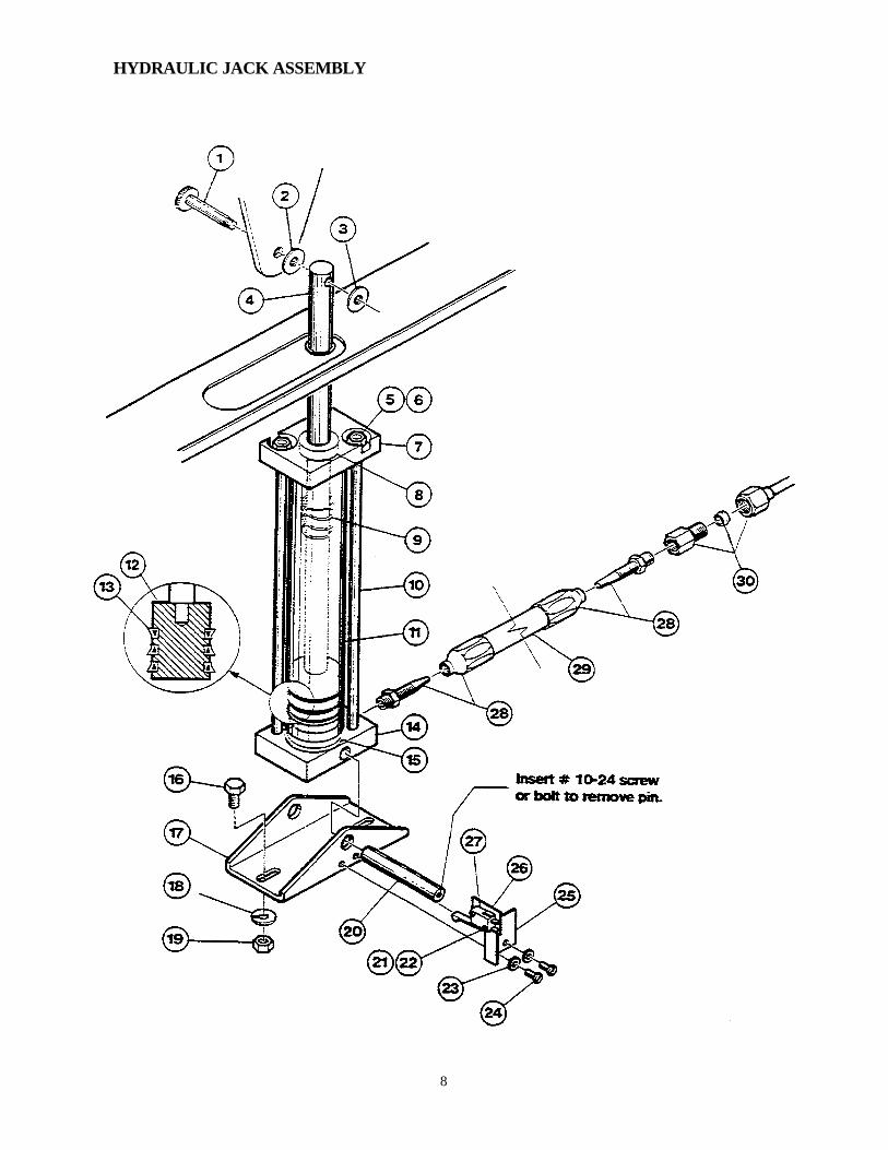
HYDRAULIC JACK ASSEMBLY
8

PARTS LIST - HYDRAULIC JACK ASSEMBLY
Item No. Part No. Description Qty. 1 SK50605 Mounting Pin, Top Jack 1 2 SK00315 Cap, Jack 1 3 FA30006 Washer 1 4-15 SK00208 Hydraulic Jack Assembly 1 4 SK50578 Piston Rod 1 5 FA20026 Hex Nut, 1/4-20 2 6 FA32008 Lockwasher, 1/4 2 7 SK50575 Cylinder Top 1 8 SK50596 Wiper Scraper Seal 1 9 SK50711 Spring 1 10 SK50579 Tie Rod 2 11 SK50576 Cylinder 1 12 SK50574 Cylinder Piston 1 13 SK50595 Wiper Seal 3 14 SK50573 Cylinder Base 1 15 SK50597 Tetra Seal 1 16 FA10603 Bolt, 5/16-18 x 3/4" 2 17 SK50541 Mounting Bracket, Hydraulic Jack 1 18 FA31009 Lockwasher, 5/16 2 19 FA20010 Hex Nut, 5/16-18 2 20 SK50552 Mounting Pin, Bottom Jack 1 21 FA10032 Screw, #4 - 40 x 5/8" 2 22 FA32002 Tooth Lockwasher, #4 2 23 FA32006 Tooth Lockwasher, #10 2 24 FA10362 Screw, #10 - 32 x 3/8" 2 25 SK50546 Bracket, Micro Switch 1 26 KE52312 Fish Paper 1 27 SK50663 Micro Switch 1 28 FI05135 Coupling 2 29 FI05136 Hydraulic Hose, 1/4" ID x 12" 1 30 FI05134 Connector 1 Use only replacement parts which are factory supplied as to preserve the certification of Underwriters Laboratories, American Gas Association, Canadian Standards Association or Canadian Gas Association (as applicable). The use of other than factory supplied replacement parts will void the warranty.
9

ELECTRIC JACK ASSEMBLY
10

PARTS LIST - ELECTRIC JACK ASSEMBLY
Item No. Part No. Description Qty. 1 SK50605 Pin, Mounting, Top Jack 1 2 SK50648 Washer 1 3-4 SK50493 Electric Jack Assembly 1 4 SE50025 Motor, Electric Jack 1 5 SK50621 Lever, Micro Switch 1 6 SK50601 Bracket, Micro Switch 1 7 KE52312 Fish Paper 1 8 FA10032 Screw, #4 - 40 x 5/8" 2 9 FA32002 Tooth Lockwasher, #4 2 10 SK50663 Micro Switch 1 11 FA10362 Screw, #10-32 x 3/8" 2 12 FA32006 Tooth Lockwasher, #10 2 13 SK50552 Mounting Pin, Bottom Jack 1 14 FA20010 Hex Nut, 5/16-18 2 15 FA31009 Lockwasher, 5/16 2 16 SK50542 Bracket Mounting, Electric Jack 1 17 FA30078 Washer 2 18 FA10603 Bolt, 5/16-18 x 3/4" 2 19 SK50644 Spacer, L.H., 3/16" Thick (SGL, SGM-30-X) 1 SK50645 Spacer, L.H.., 1/4" Thick (SGL, SGM-40-X) 1 20 SK50647 Spacer, R.H., 1/2" Thick (SGL, SGM-30-X) 1 SK50646 Spacer, R.H., 7/16" Thick (SGL, SGM-40-X) 1 Use only replacement parts which are factory supplied as to preserve the certification of Underwriters Laboratories, American Gas Associ ation, Canadian Standards Association or Canadian Gas Association (as applicable). The use of other than factory supplied replacement parts will void the warranty.
11
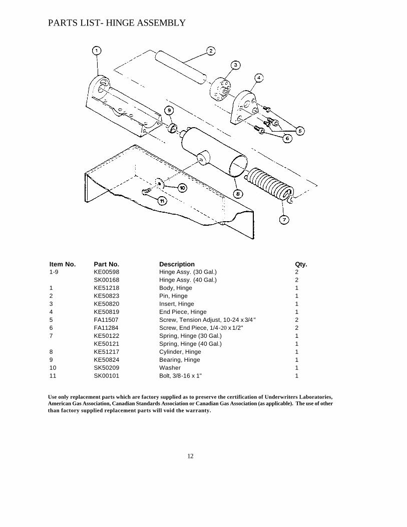
PARTS LIST- HINGE ASSEMBLY
Item No. Part No. Description Qty. 1-9 KE00598 Hinge Assy. (30 Gal.) 2 SK00168 Hinge Assy. (40 Gal.) 2 1 KE51218 Body, Hinge 1 2 KE50823 Pin, Hinge 1 3 KE50820 Insert, Hinge 1 4 KE50819 End Piece, Hinge 1 5 FA11507 Screw, Tension Adjust, 10-24 x 3/4" 2 6 FA11284 Screw, End Piece, 1/4-20 x 1/2" 2 7 KE50122 Spring, Hinge (30 Gal.) 1 KE50121 Spring, Hinge (40 Gal.) 1 8 KE51217 Cylinder, Hinge 1 9 KE50824 Bearing, Hinge 1 10 SK50209 Washer 1 11 SK00101 Bolt, 3/8-16 x 1" 1 Use only replacement parts which are factory supplied as to preserve the certification of Underwriters Laboratories, American Gas Association, Canadian Standards Association or Canadian Gas Association (as applicable). The use of other than factory supplied replacement parts will void the warranty.
12

PARTS LIST- COVER-VENT CAP AND DEFLECTOR
Item No. Part No. Description Qty 1 SK00105 Screw, 1/4-20 x 3/8" 1 2 SK50179 Washer 1 3-6 SK00054 Vent Cap Assy. 1 3 SK51032 Support Arm 1 4 SK50218 Knob 1 5 SK50131 Spacer 1 6 SK00059 Cover 1 7 SK50133 Spacer 1 8 SK50444 Knob 3,4* 9 SK00175 Deflector Assy. (30 Gal.) 1
SK00176 Deflector Assy. (40 Gal.) 1
*The first figure applies to 30 gal. skillets, the second figure applies to 40 gal. skillets
Use only replacement parts which are factory supplied as to preserve the certification of Underwriters Laboratories, American Gas Association, Canadian Standards Association or Canadian Gas Association (as applicable). The use of other than factory supplied replacement parts will void the warranty.
13

14
PARTS LIST - FAUCET
Item No. Part No. Description Qty.
1 SE50020 Hot Water Stem Assy. 1 2 SE50021 Cold Water Stem Assy. 1 3 SE50022 Yoke Connection Kit 1 4 FA00016 "0" Ring 1 5 FA95022 Retaining Ring 1 6 KE51736 Spout Nut 1 7 KE50832 3/4" Spout, 10" (A) x 9" (B) 1 8 KE51401 Single Pantry Control Valve (c/w Item No. 2) 1 9 KE51403 Double Pantry Control Valve 1 (c/w Item No. 1,2,3) 10 SK00212 Faucet Mounting Bracket 1 11 FA11272 Bolt, 1/4-28 UNF x 3/4" 2
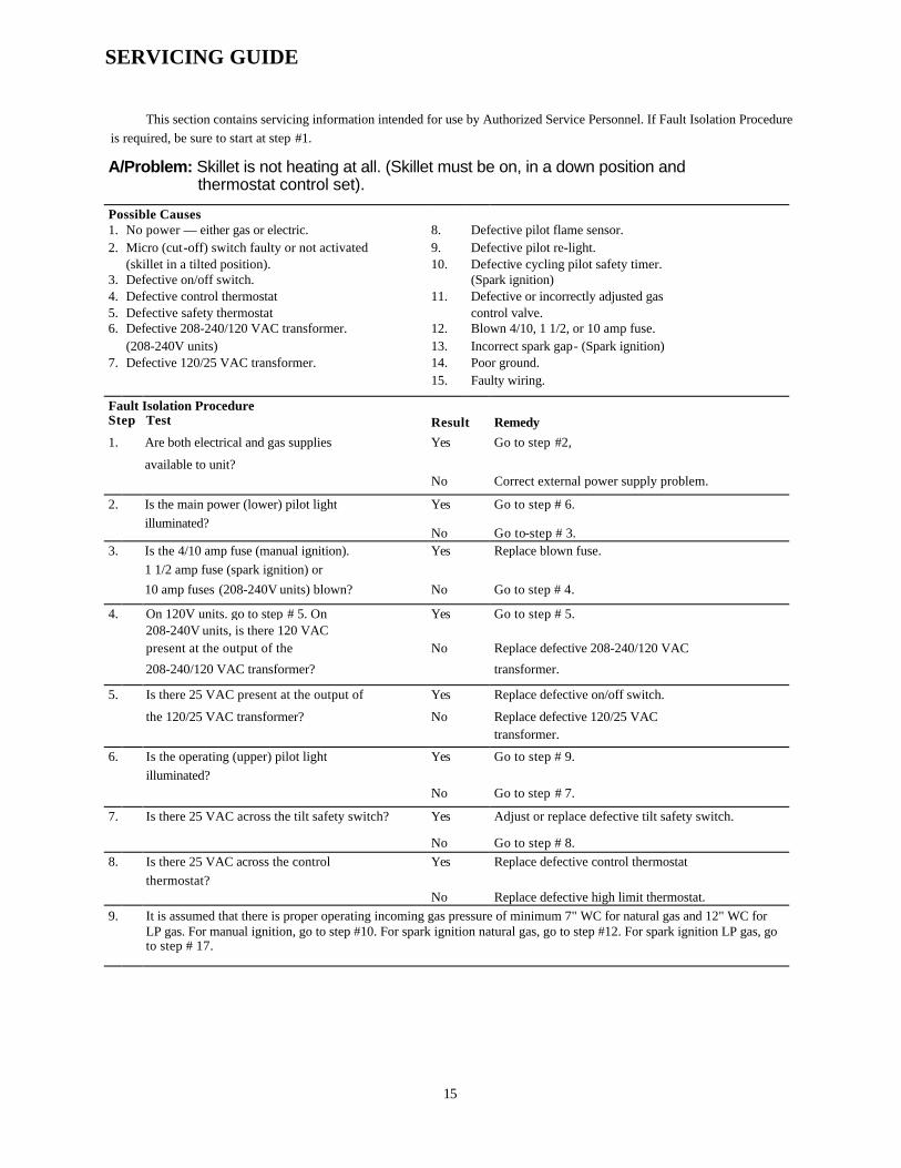
SERVICING GUIDE
This section contains servicing information intended for use by Authorized Service Personnel. If Fault Isolation Procedure is required, be sure to start at step #1.
A/Problem: Skillet is not heating at all. (Skillet must be on, in a down position and thermostat control set).
Possible Causes 1. No power — either gas or electric. 8. Defective pilot flame sensor. 2. Micro (cut-off) switch faulty or not activated 9. Defective pilot re-light. (skillet in a tilted position). 10. Defective cycling pilot safety timer. 3. Defective on/off switch. (Spark ignition) 4. Defective control thermostat 11. Defective or incorrectly adjusted gas 5. Defective safety thermostat control valve. 6. Defective 208-240/120 VAC transformer. 12. Blown 4/10, 1 1/2, or 10 amp fuse. (208-240V units) 13. Incorrect spark gap- (Spark ignition) 7. Defective 120/25 VAC transformer. 14. Poor ground.
15. Faulty wiring.
Fault Isolation Procedure Step Test
Result
Remedy
1. Are both electrical and gas supplies
available to unit?
Yes Go to step #2,
No Correct external power supply problem.
2. Is the main power (lower) pilot light Yes Go to step # 6.
illuminated? No Go to-step # 3.
3. Is the 4/10 amp fuse (manual ignition). Replace blown fuse.
1 1/2 amp fuse (spark ignition) or Yes
10 amp fuses (208-240V units) blown? No Go to step # 4.
4. On 120V units. go to step # 5. On
208-240V units, is there 120 VAC Yes Go to step # 5.
present at the output of the Replace defective 208-240/120 VAC
208-240/120 VAC transformer?
No
transformer.
5.
Is there 25 VAC present at the output of Yes Replace defective on/off switch.
the 120/25 VAC transformer? Replace defective 120/25 VAC
No transformer.
6.
Is the operating (upper) pilot light
illuminated? Yes Go to step # 9.
No Go to step # 7.
7.
Is there 25 VAC across the tilt safety switch? Yes Adjust or replace defective tilt safety switch.
No Go to step # 8. 8. Is there 25 VAC across the control Yes Replace defective control thermostat
thermostat? No Replace defective high limit thermostat.
9.
It is assumed that there is proper operating incoming gas pressure of minimum 7" WC for natural gas and 12" WC for LP gas. For manual ignition, go to step #10. For spark ignition natural gas, go to step #12. For spark ignition LP gas, go to step # 17.
15

10. Can a pilot light be achieved? Yes Refer to Pilot Flame Adjustment Procedure and adjust flame if necessary. If adjustment is not required or unsuccessful, go to step #11.
No Replace defective gas control valve.
11. Does the pilot flame sensor (thermopile) generate 450-750 mV?
Yes Replace defective gas control valve.
No Replace defective pilot flame sensor.
12. Look through peep hole. Can a pilot flame be achieved?
Yes Go to step # 16.
No Go to step # 13.
13. Is a spark being generated? Yes Go to step # 15.
No Go to step # 14.
14. Is the spark gap 1/8" ± 1/32"? Yes Replace defective pilot re-light
No Adjust spark gap.
15. Yes Replace defective gas control valve.
Measure continuity across pilot flame sensor's pins #3 and #4. is it a closed circuit?
No Replace defective pilot flame sensor.
16. Yes Replace defective gas control valve.
After pilot has been lit for 5 minutes, pull pilot flame sensor's connection off and quickly measure continuity between pins #2 and #4. Is it a closed circuit at first and after pilot flame sensor cools down the circuit opens?
No Refer to Pilot Flame Adjustment Procedure and adjust flame if necessary. If adjustment is not required or unsuccessful, replace defective pilot flame sensor.
17. Yes Go to step # 19.
Look through peep hole- Is a spark being generated?
No Go to step # 18.
18. Is the spark gap 1/8" ± 1/32"? Yes Replace defective pilot re-light
No Adjust spark gap.
19. Yes If burners now fail to ignite, go to step #21.
Turn power on/off switch to "off" for 5 minutes. This wit! zero the cycling pilot safety timer. Then turn unit back on. Is a pilot flame now available? No Go to step # 20.
20. Measure continuity across pilot flame sensor's pins #3 and #4. Is it a closed circuit?
Yes Replace either defective cycling pilot safety timer or gas control valve. (Note: Gas control valve would be the more reliable component)
No Replace defective pilot flame sensor.
21. Yes Replace defective gas control valve.
After pilot has been lit and just as pilot goes out due to cycling pilot safety timer, pull pilot flame sensor's connection off and quickly measure continuity between pins #2 and #4. Is it a closed circuit at first and after pilot flame sensor cools down the circuit opens?
No Refer to Pilot Flame Adjustment Procedure and adjust flame if necessary. If adjustment is not required or unsuccessful, replace defective pilot flame sensor.
16
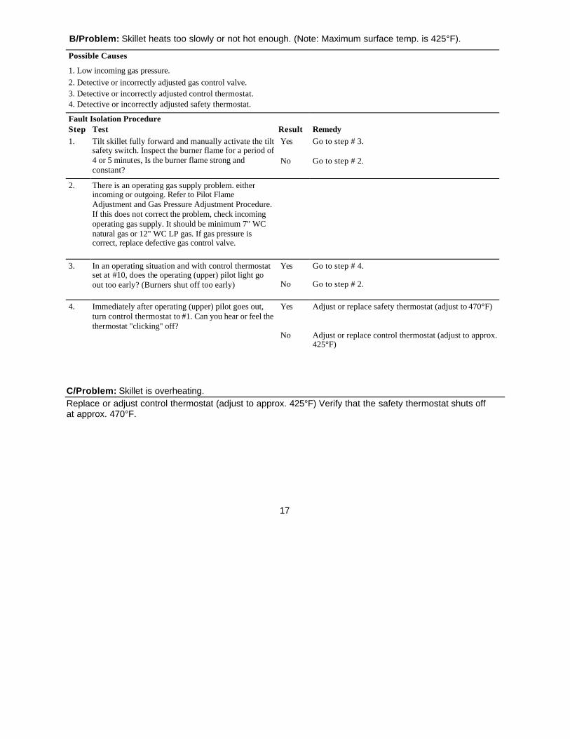
B/Problem: Skillet heats too slowly or not hot enough. (Note: Maximum surface temp. is 425°F).
Possible Causes
1. Low incoming gas pressure. 2. Detective or incorrectly adjusted gas control valve.
3. Detective or incorrectly adjusted control thermostat. 4. Detective or incorrectly adjusted safety thermostat.
Fault Isolation Procedure Step Test Result Remedy 1. Yes Go to step # 3.
Tilt skillet fully forward and manually activate the tilt safety switch. Inspect the burner flame for a period of 4 or 5 minutes, Is the burner flame strong and constant?
No Go to step # 2.
2. There is an operating gas supply problem. either incoming or outgoing. Refer to Pilot Flame Adjustment and Gas Pressure Adjustment Procedure. If this does not correct the problem, check incoming operating gas supply. It should be minimum 7" WC natural gas or 12" WC LP gas. If gas pressure is correct, replace defective gas control valve.
3. Yes Go to step # 4.
In an operating situation and with control thermostat set at #10, does the operating (upper) pilot light go out too early? (Burners shut off too early) No Go to step # 2.
4. Yes Adjust or replace safety thermostat (adjust to 470°F)
Immediately after operating (upper) pilot goes out, turn control thermostat to #1. Can you hear or feel the thermostat "clicking" off?
No Adjust or replace control thermostat (adjust to approx. 425°F)
C/Problem: Skillet is overheating. Replace or adjust control thermostat (adjust to approx. 425°F) Verify that the safety thermostat shuts off at approx. 470°F.
17
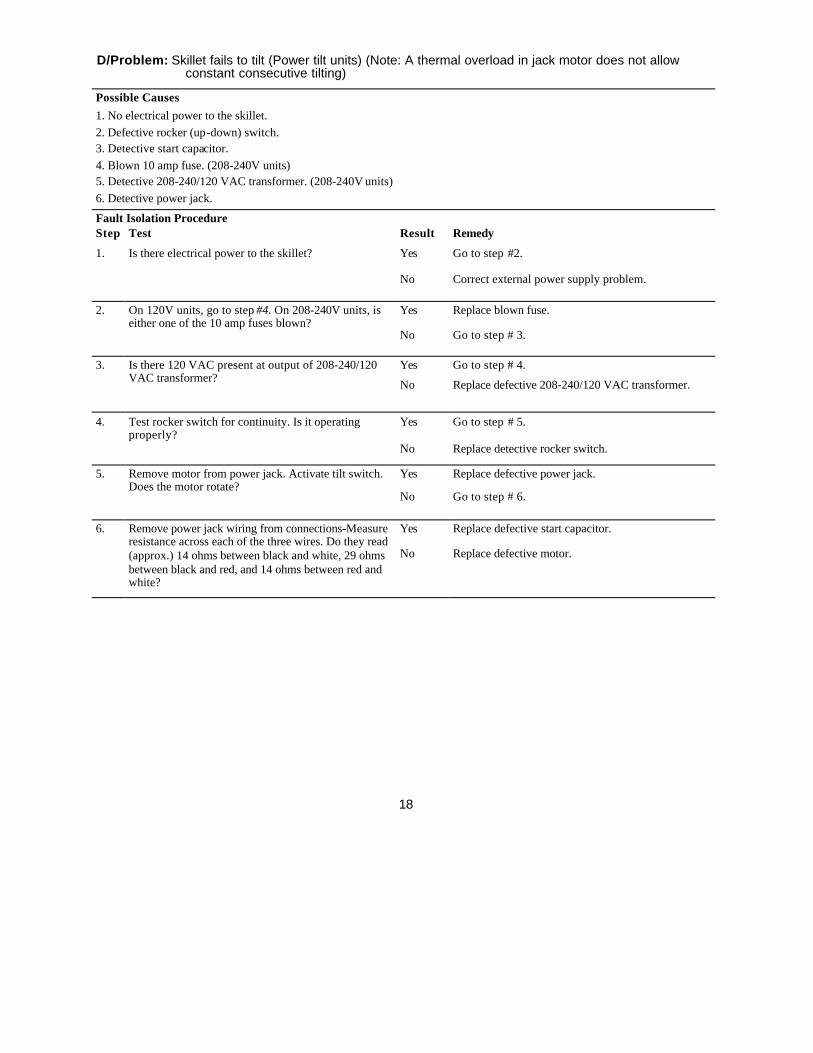
D/Problem: Skillet fails to tilt (Power tilt units) (Note: A thermal overload in jack motor does not allow constant consecutive tilting)
Possible Causes 1. No electrical power to the skillet. 2. Defective rocker (up-down) switch. 3. Detective start capacitor. 4. Blown 10 amp fuse. (208-240V units) 5. Detective 208-240/120 VAC transformer. (208-240V units) 6. Detective power jack. Fault Isolation Procedure Step Test Result Remedy 1. Is there electrical power to the skillet? Yes Go to step #2.
No Correct external power supply problem.
2. Yes Replace blown fuse.
On 120V units, go to step #4. On 208-240V units, is either one of the 10 amp fuses blown?
No Go to step # 3.
3. Yes Go to step # 4.
Is there 120 VAC present at output of 208-240/120 VAC transformer? No Replace defective 208-240/120 VAC transformer.
4. Yes Go to step # 5.
Test rocker switch for continuity. Is it operating properly?
No Replace detective rocker switch.
5. Yes Replace defective power jack.
Remove motor from power jack. Activate tilt switch. Does the motor rotate?
No Go to step # 6.
6. Yes Replace defective start capacitor.
Remove power jack wiring from connections-Measure resistance across each of the three wires. Do they read (approx.) 14 ohms between black and white, 29 ohms between black and red, and 14 ohms between red and white?
No Replace defective motor.
18

GAS PRESSURE ADJUSTMENT PROCEDURE
CAUTION: The following procedure, as well as other work on gas controls should be performed only by a qualified service technician.
NOTE: Gas pressure adjustment is pre-set and rarely needs any adjustment 1. Remove gas pressure adjustment cover screw. 2. Operating gas pressure output should be regulated to 6" W.C. natural gas and 11" W.C. LP gas. 3. Turn gas pressure adjustment screw (under cover screw) clockwise to increase or
counterclockwise to decrease gas pressure. 4. Replace cover screw.
PILOT FLAME ADJUSTMENT PROCEDURE
CAUTION: The following procedure, as well as all other work on gas controls should be performed only by a qualified service technician.
1. Remove pilot adjustment cover screw. 2. Turn pilot flow adjustment screw (under cover screw) clockwise to increase flame (see
below drawing for correct flame adjustment). 3. Replace cover screw.
19

HYDRAULIC JACK REPLACEMENT PROCEDURE
Refer to "Hydraulic Jack Assembly" drawing.
1. Place skillet pan in a down position.
2. Remove jack's top mounting pin (1).
3. Remove micro switch bracket (25) by removing screws (24).
4. Insert a #10-24 screw or bolt into jack's bottom mounting pin (20) and pull pin away from jack to remove.
5. Disconnect hydraulic hose (28, 29) at connector (30).
6. Remove jack from skillet
7. Disconnect hydraulic hose from old jack and connect to new jack.
8. Ensure replacement jack is in a down position and place end of hydraulic hose into pump's oil tank by removing 3/4" plug. Draw out jack's piston rod so that oil is drawn into hydraulic hose.
9. Remove hose from tank and turn jack upside down. Push in on the jack's piston rod. Oil with air bubbles will seep out the end of the hydraulic hose. Continue pushing down on the rod until all air bubbles stop and only oil is being emitted.
10. Follow steps 1 through 6 in reverse order to re-assemble.
NOTE: If alot of oil has been lost, check oil level in oil tank. It should be filled to approximately 1/2" from top of tank with standard motor oil (SAE-30).
POWER JACK REMOVAL PROCEDURE
WARNING: Skillet pan is heavy and support should always be given to pan if jack is being removed.
1. Remove top jack mounting pin.
2. Remove bottom jack mounting pins retaining bracket
3. Remove bottom jack mounting pin by inserting a #10-24 screw or bolt into the pin and pulling towards the interior of the skillet
4. There should now be plenty of clearance to remove jack.
20

HYDRAULIC PUMP REPLACEMENT AND AIR BLEEDING PROCEDURE (units after April 1,1988)
NOTE: Bleeding the pump of air is necessary if air has entered hydraulic lines, jack, or pump. If pump is not being replaced omit step #6.
Refer to "Hydraulic Lift Mechanism" drawing.
1. Place skillet pan in a down position.
2. Remove hand wheel (17) by loosening set screw (18).
3. Remove hydraulic line nut (8) from elbow (6).
4. Remove bolts (20) that secure pump to frame.
5. Remove pump (21) from unit
6. Remove oil tank (1) from old pump and re-connect onto new pump. Pour oil out of old tank and into new tank.
7. Tilt oil tank up at back so that oil flows toward pump.
8. Turn pump shaft counter-clockwise until oil starts to seep out of elbow.
9. Set pump and oil tank down so that oil tank is sitting flat on surface- Support pump so that it will not tip forward.
10. Turn pump shaft counter-clockwise while applying slight pressure with finger on opening of elbow. Oil and air bubbles should seep out Continue to do this until all air bubbles stop and only oil is being emitted.
11. Re-install pump into unit securing with mounting bolts.
12. Re-connect hydraulic line to elbow.
13. Re-install hand wheel.
NOTE: If alot of oil has been lost, check oil level in oil tank. It should be filled to approximately 1/2 from top of tank with standard motor oil (SAE-30).
21

HINGE ADJUSTMENT INSTRUCTIONS
1. Insert 3/8" Allen wrench.
2. Turn clockwise relieve tension on spring.
3. While tension is released remove one of the two slotted screws.
4. To prevent Allen wrench from springing back abruptly while the second slotted screw is removed, insert a pin (approximately 1/8") in the hole where the first slotted screw was removed from.
5. Remove second slotted screw.
6. While holding Allen wrench remove pin.
7. Turn Allen wrench clockwise to tighten or counter-clockwise to loosen tension to produce desired effect
8. Re-insert pin in one of the two holes.
9. Tighten one slotted screw in the other hole (it may be necessary to turn Allen wrench slightly to align holes.)
10. Remove pin and repeat step number 9 for other slotted screw.
22

WIRING DIAGRAM - SPARK IGNITION
23
WIRING DIAGRAM -MANUAL IGNITION