Embed Size (px)
Citation preview
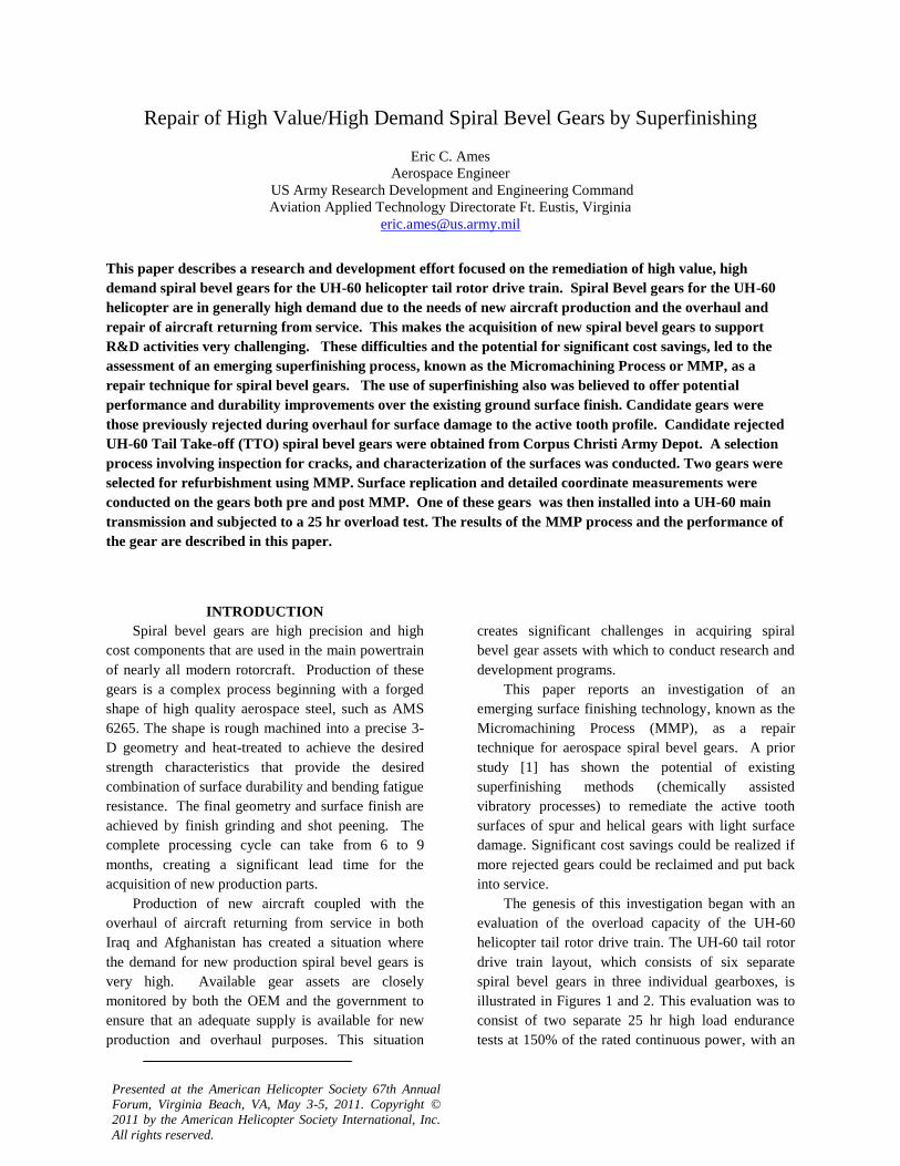
Repair of High Value/High Demand Spiral Bevel Gears by Superfinishing
Eric C. Ames
Aerospace Engineer
US Army Research Development and Engineering Command
Aviation Applied Technology Directorate Ft. Eustis, Virginia
This paper describes a research and development effort focused on the remediation of high value, high
demand spiral bevel gears for the UH-60 helicopter tail rotor drive train. Spiral Bevel gears for the UH-60
helicopter are in generally high demand due to the needs of new aircraft production and the overhaul and
repair of aircraft returning from service. This makes the acquisition of new spiral bevel gears to support
R&D activities very challenging. These difficulties and the potential for significant cost savings, led to the
assessment of an emerging superfinishing process, known as the Micromachining Process or MMP, as a
repair technique for spiral bevel gears. The use of superfinishing also was believed to offer potential
performance and durability improvements over the existing ground surface finish. Candidate gears were
those previously rejected during overhaul for surface damage to the active tooth profile. Candidate rejected
UH-60 Tail Take-off (TTO) spiral bevel gears were obtained from Corpus Christi Army Depot. A selection
process involving inspection for cracks, and characterization of the surfaces was conducted. Two gears were
selected for refurbishment using MMP. Surface replication and detailed coordinate measurements were
conducted on the gears both pre and post MMP. One of these gears was then installed into a UH-60 main
transmission and subjected to a 25 hr overload test. The results of the MMP process and the performance of
the gear are described in this paper.
INTRODUCTION
Spiral bevel gears are high precision and high
cost components that are used in the main powertrain
of nearly all modern rotorcraft. Production of these
gears is a complex process beginning with a forged
shape of high quality aerospace steel, such as AMS
6265. The shape is rough machined into a precise 3-
D geometry and heat-treated to achieve the desired
strength characteristics that provide the desired
combination of surface durability and bending fatigue
resistance. The final geometry and surface finish are
achieved by finish grinding and shot peening. The
complete processing cycle can take from 6 to 9
months, creating a significant lead time for the
acquisition of new production parts.
Production of new aircraft coupled with the
overhaul of aircraft returning from service in both
Iraq and Afghanistan has created a situation where
the demand for new production spiral bevel gears is
very high. Available gear assets are closely
monitored by both the OEM and the government to
ensure that an adequate supply is available for new
production and overhaul purposes. This situation
creates significant challenges in acquiring spiral
bevel gear assets with which to conduct research and
development programs.
This paper reports an investigation of an
emerging surface finishing technology, known as the
Micromachining Process (MMP), as a repair
technique for aerospace spiral bevel gears. A prior
study [1] has shown the potential of existing
superfinishing methods (chemically assisted
vibratory processes) to remediate the active tooth
surfaces of spur and helical gears with light surface
damage. Significant cost savings could be realized if
more rejected gears could be reclaimed and put back
into service.
The genesis of this investigation began with an
evaluation of the overload capacity of the UH-60
helicopter tail rotor drive train. The UH-60 tail rotor
drive train layout, which consists of six separate
spiral bevel gears in three individual gearboxes, is
illustrated in Figures 1 and 2. This evaluation was to
consist of two separate 25 hr high load endurance
tests at 150% of the rated continuous power, with an
Presented at the American Helicopter Society 67th Annual
Forum, Virginia Beach, VA, May 3-5, 2011. Copyright ©
2011 by the American Helicopter Society International, Inc.
All rights reserved.
additional test at 170% power with transients up to
200%.
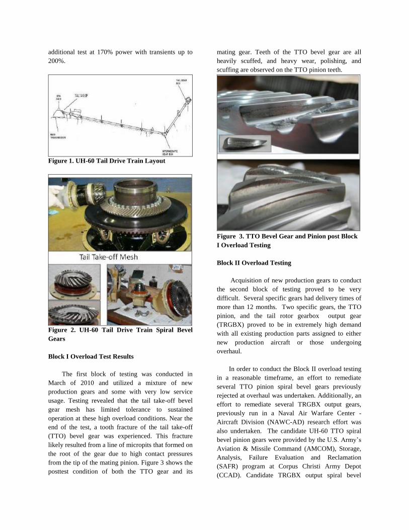
Figure 1. UH-60 Tail Drive Train Layout
Figure 2. UH-60 Tail Drive Train Spiral Bevel
Gears
Block I Overload Test Results
The first block of testing was conducted in
March of 2010 and utilized a mixture of new
production gears and some with very low service
usage. Testing revealed that the tail take-off bevel
gear mesh has limited tolerance to sustained
operation at these high overload conditions. Near the
end of the test, a tooth fracture of the tail take-off
(TTO) bevel gear was experienced. This fracture
likely resulted from a line of micropits that formed on
the root of the gear due to high contact pressures
from the tip of the mating pinion. Figure 3 shows the
posttest condition of both the TTO gear and its
mating gear. Teeth of the TTO bevel gear are all
heavily scuffed, and heavy wear, polishing, and
scuffing are observed on the TTO pinion teeth.
Figure 3. TTO Bevel Gear and Pinion post Block
I Overload Testing
Block II Overload Testing
Acquisition of new production gears to conduct
the second block of testing proved to be very
difficult. Several specific gears had delivery times of
more than 12 months. Two specific gears, the TTO
pinion, and the tail rotor gearbox output gear
(TRGBX) proved to be in extremely high demand
with all existing production parts assigned to either
new production aircraft or those undergoing
overhaul.
In order to conduct the Block II overload testing
in a reasonable timeframe, an effort to remediate
several TTO pinion spiral bevel gears previously
rejected at overhaul was undertaken. Additionally, an
effort to remediate several TRGBX output gears,
previously run in a Naval Air Warfare Center -
Aircraft Division (NAWC-AD) research effort was
also undertaken. The candidate UH-60 TTO spiral
bevel pinion gears were provided by the U.S. Army’s
Aviation & Missile Command (AMCOM), Storage,
Analysis, Failure Evaluation and Reclamation
(SAFR) program at Corpus Christi Army Depot
(CCAD). Candidate TRGBX output spiral bevel
gears were provided by NAWC-AD Propulsion and
Power Division at Naval air Station, Patuxent River,
MD. These gears were utilized to support previous
UH-60 drive train seeded fault testing at NAWC-AD.
Only the results of the remediation work on the TTO
bevel pinions will be discussed in this paper, as the
approach for the two different configurations was
very similar.
The Army’s SAFR Program provides expert
parts failure analysis, repair development and
remediation solutions to military aviation maintainers
in support of their critical supply needs. SAFR
accomplishes this by collecting “select mission
essential” candidate parts removed at CCAD or other
depot maintenance facilities. These candidate parts
no longer meet current technical repair criteria, or are
“Beyond Economical Repair” (BER) due to funding,
maintenance capability or obsolescence issues. SAFR
does not collect crash damaged or mutilated parts.
Candidate parts selection is based upon critical
supply need, complexity to manufacture, raw
materials availability and/or long procurement lead
times. The high cost and demand for rotorcraft spiral
bevel gears makes them a significant item for the
SAFR program.
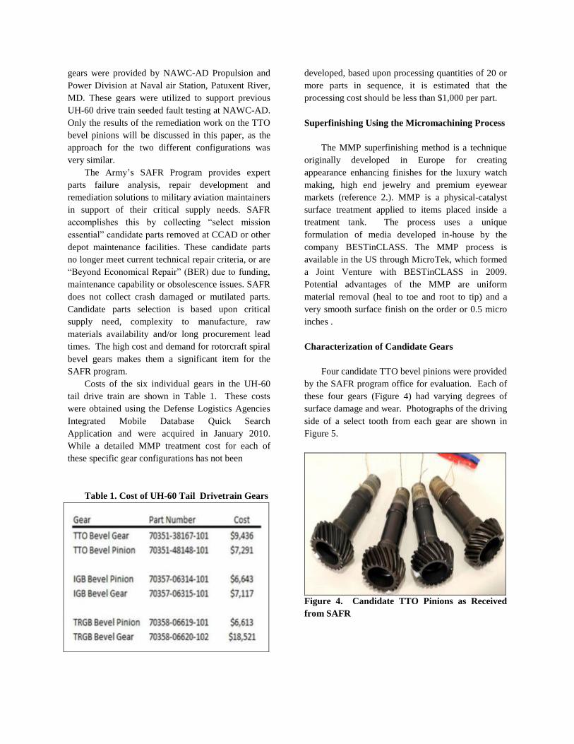
Costs of the six individual gears in the UH-60
tail drive train are shown in Table 1. These costs
were obtained using the Defense Logistics Agencies
Integrated Mobile Database Quick Search
Application and were acquired in January 2010.
While a detailed MMP treatment cost for each of
these specific gear configurations has not been
Table 1. Cost of UH-60 Tail Drivetrain Gears
developed, based upon processing quantities of 20 or
more parts in sequence, it is estimated that the
processing cost should be less than $1,000 per part.
Superfinishing Using the Micromachining Process
The MMP superfinishing method is a technique
originally developed in Europe for creating
appearance enhancing finishes for the luxury watch
making, high end jewelry and premium eyewear
markets (reference 2.). MMP is a physical-catalyst
surface treatment applied to items placed inside a
treatment tank. The process uses a unique
formulation of media developed in-house by the
company BESTinCLASS. The MMP process is
available in the US through MicroTek, which formed
a Joint Venture with BESTinCLASS in 2009.
Potential advantages of the MMP are uniform
material removal (heal to toe and root to tip) and a
very smooth surface finish on the order or 0.5 micro
inches .
Characterization of Candidate Gears
Four candidate TTO bevel pinions were provided
by the SAFR program office for evaluation. Each of
these four gears (Figure 4) had varying degrees of
surface damage and wear. Photographs of the driving
side of a select tooth from each gear are shown in
Figure 5.
Figure 4. Candidate TTO Pinions as Received
from SAFR

Figure 5. Driving Tooth Surfaces of Candidate
Pinions
The candidate pinions were first sent to Overhaul
Support Services (OSS), East Granby CT for
nondestructive testing and ranking of the candidates
in terms of suitability for repair and reassembly into
the test gearbox. OSS is a FAA certified overhaul
and repair facility specializing in dynamic
components for Sikorsky Aircraft. Each of the
pinions was subject to a magnetic particle inspection
and found to be free of cracks. OSS ranked the
damage of each of the pinions and recommended that
two pinions (SN C518-00159 and SN A518-00011)
were best suited for repair with SN C518-00159
being the least damaged.
These two pinions were then sent to Wedeven
Associates (WA), Edgmont, PA for detailed
characterization of the gear tooth surfaces. The
techniques used by WA involved making silicone
replicas of the gear teeth surfaces and subsequently
using a Phase Shift Surface Interferometer to create
3-D representations of the tooth surfaces. These
digital surface models were then analyzed to
determine features such as overall roughness, wear
and the maximum depth of specific defects or pits.
The replica material utilized, 101RF (general
purpose/fast curing), was manufactured by Microset
Product, Ltd. Warwickshire, UK. This product has
been shown to have extreme sensitivity that can
allow replication of the surface within 10
nanometers. Close-up photographs of the gear tooth
surfaces and the associated silicone replicas are
shown in Figures 6 and 7.
Figure 6. Silicone Replica of TTO Bevel Pinion SN
C518-00159
Figure 7. Silicone Replica of TTO Bevel Pinion SN
A518-00011
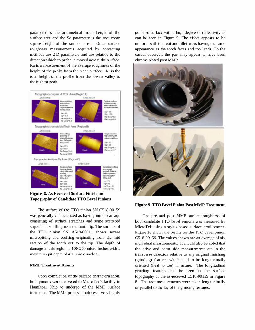
The approximate tooth height from root to tip is
0.31 inches. Three-dimensional analysis of the
replicated surfaces was conducted at mid-span of the
tooth face width as shown in the figures. Specific
regions near the root, center, and tip were analyzed
for mean surface roughness (Sa) and maximum pit
depth. Results of this analysis are shown in Figure 8.
To enhance the visual appearance of the surface
features, a 20X magnification in the Z direction
(depth) was applied.
It should be noted that the surface roughness
measurements acquired by various optical methods
discussed in this paper (Phase Shift Surface
Interferometry and Confocal Microscopy) are shown
as 3-D parameters based upon an analysis of a
defined local area of the gear tooth surface. The Sa
parameter is the arithmetical mean height of the
surface area and the Sq parameter is the root mean
square height of the surface area. Other surface
roughness measurements acquired by contacting
methods are 2-D parameters and are relative to the
direction which to probe is moved across the surface.
Ra is a measurement of the average roughness or the
height of the peaks from the mean surface. Rt is the
total height of the profile from the lowest valley to
the highest peak.
Figure 8. As Received Surface Finish and
Topography of Candidate TTO Bevel Pinions
The surface of the TTO pinion SN C518-00159
was generally characterized as having minor damage
consisting of surface scratches and some scattered
superficial scuffing near the tooth tip. The surface of
the TTO pinion SN A519-00011 shows severe
micropitting and scuffing originating from the mid
section of the tooth out to the tip. The depth of
damage in this region is 100-200 micro-inches with a
maximum pit depth of 400 micro-inches.
MMP Treatment Results
Upon completion of the surface characterization,
both pinions were delivered to MicroTek’s facility in
Hamilton, Ohio to undergo of the MMP surface
treatment. The MMP process produces a very highly
polished surface with a high degree of reflectivity as
can be seen in Figure 9. The effect appears to be
uniform with the root and fillet areas having the same
appearance as the tooth faces and top lands. To the
casual observer, the part may appear to have been
chrome plated post MMP.
Figure 9. TTO Bevel Pinion Post MMP Treatment
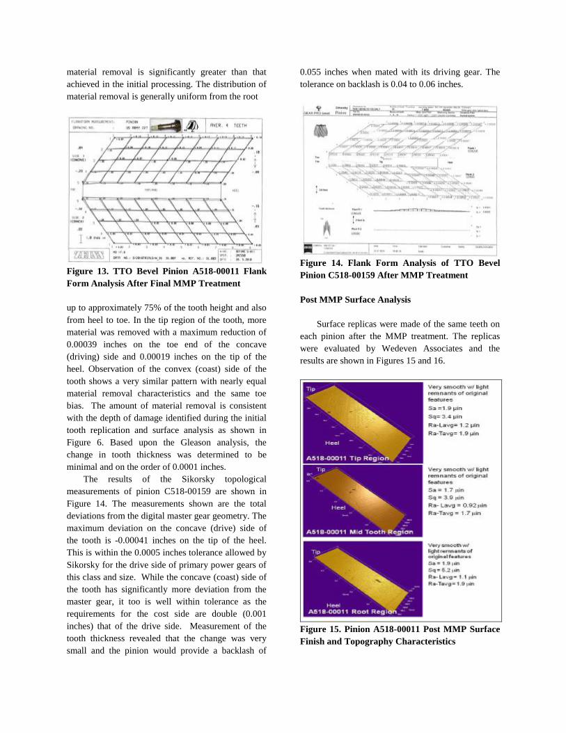
The pre and post MMP surface roughness of
both candidate TTO bevel pinions was measured by
MicroTek using a stylus based surface profilometer.
Figure 10 shows the results for the TTO bevel pinion
C518-00159. The values shown are an average of six
individual measurements. It should also be noted that
the drive and coast side measurements are in the
transverse direction relative to any original finishing
(grinding) features which tend to be longitudinally
oriented (heal to toe) in nature. The longitudinal
grinding features can be seen in the surface
topography of the as-received C518-00159 in Figure
8. The root measurements were taken longitudinally
or parallel to the lay of the grinding features.
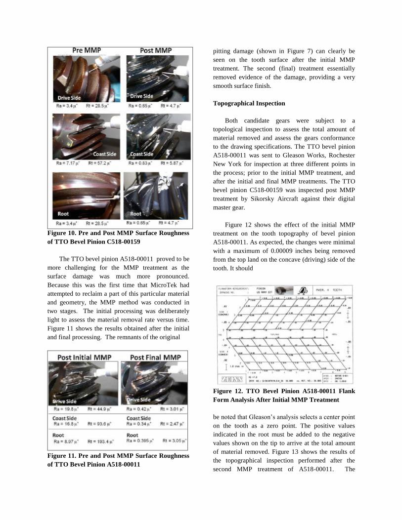
Figure 10. Pre and Post MMP Surface Roughness
of TTO Bevel Pinion C518-00159
The TTO bevel pinion A518-00011 proved to be
more challenging for the MMP treatment as the
surface damage was much more pronounced.
Because this was the first time that MicroTek had
attempted to reclaim a part of this particular material
and geometry, the MMP method was conducted in
two stages. The initial processing was deliberately
light to assess the material removal rate versus time.
Figure 11 shows the results obtained after the initial
and final processing. The remnants of the original
Figure 11. Pre and Post MMP Surface Roughness
of TTO Bevel Pinion A518-00011
pitting damage (shown in Figure 7) can clearly be
seen on the tooth surface after the initial MMP
treatment. The second (final) treatment essentially
removed evidence of the damage, providing a very
smooth surface finish.
Topographical Inspection
Both candidate gears were subject to a
topological inspection to assess the total amount of
material removed and assess the gears conformance
to the drawing specifications. The TTO bevel pinion
A518-00011 was sent to Gleason Works, Rochester
New York for inspection at three different points in
the process; prior to the initial MMP treatment, and
after the initial and final MMP treatments. The TTO
bevel pinion C518-00159 was inspected post MMP
treatment by Sikorsky Aircraft against their digital
master gear.
Figure 12 shows the effect of the initial MMP
treatment on the tooth topography of bevel pinion
A518-00011. As expected, the changes were minimal
with a maximum of 0.00009 inches being removed
from the top land on the concave (driving) side of the
tooth. It should
Figure 12. TTO Bevel Pinion A518-00011 Flank
Form Analysis After Initial MMP Treatment
be noted that Gleason’s analysis selects a center point
on the tooth as a zero point. The positive values
indicated in the root must be added to the negative
values shown on the tip to arrive at the total amount
of material removed. Figure 13 shows the results of
the topographical inspection performed after the
second MMP treatment of A518-00011. The
material removal is significantly greater than that
achieved in the initial processing. The distribution of
material removal is generally uniform from the root
Figure 13. TTO Bevel Pinion A518-00011 Flank
Form Analysis After Final MMP Treatment
up to approximately 75% of the tooth height and also
from heel to toe. In the tip region of the tooth, more
material was removed with a maximum reduction of
0.00039 inches on the toe end of the concave
(driving) side and 0.00019 inches on the tip of the
heel. Observation of the convex (coast) side of the
tooth shows a very similar pattern with nearly equal
material removal characteristics and the same toe
bias. The amount of material removal is consistent
with the depth of damage identified during the initial
tooth replication and surface analysis as shown in
Figure 6. Based upon the Gleason analysis, the
change in tooth thickness was determined to be
minimal and on the order of 0.0001 inches.
The results of the Sikorsky topological
measurements of pinion C518-00159 are shown in
Figure 14. The measurements shown are the total
deviations from the digital master gear geometry. The
maximum deviation on the concave (drive) side of
the tooth is -0.00041 inches on the tip of the heel.
This is within the 0.0005 inches tolerance allowed by
Sikorsky for the drive side of primary power gears of
this class and size. While the concave (coast) side of
the tooth has significantly more deviation from the
master gear, it too is well within tolerance as the
requirements for the cost side are double (0.001
inches) that of the drive side. Measurement of the
tooth thickness revealed that the change was very
small and the pinion would provide a backlash of
0.055 inches when mated with its driving gear. The
tolerance on backlash is 0.04 to 0.06 inches.
Figure 14. Flank Form Analysis of TTO Bevel
Pinion C518-00159 After MMP Treatment
Post MMP Surface Analysis
Surface replicas were made of the same teeth on
each pinion after the MMP treatment. The replicas
were evaluated by Wedeven Associates and the
results are shown in Figures 15 and 16.
Figure 15. Pinion A518-00011 Post MMP Surface
Finish and Topography Characteristics
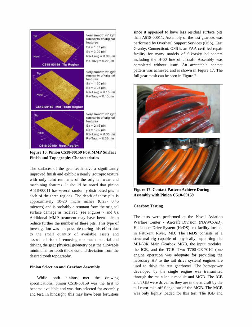
Figure 16. Pinion C518-00159 Post MMP Surface
Finish and Topography Characteristics
The surfaces of the gear teeth have a significantly
improved finish and exhibit a nearly isotropic texture
with only faint remnants of the original wear and
machining features. It should be noted that pinion
A518-00011 has several randomly distributed pits in
each of the three regions. The depth of these pits is
approximately 10-20 micro inches (0.23- 0.45
microns) and is probably a remnant from the original
surface damage as received (see Figures 7 and 8).
Additional MMP treatment may have been able to
reduce further the number of these pits. This type of
investigation was not possible during this effort due
to the small quantity of available assets and
associated risk of removing too much material and
driving the gear physical geometry past the allowable
minimums for tooth thickness and deviation from the
desired tooth topography.
Pinion Selection and Gearbox Assembly
While both pinions met the drawing
specifications, pinion C518-00159 was the first to
become available and was thus selected for assembly
and test. In hindsight, this may have been fortuitous
since it appeared to have less residual surface pits
than A518-00011. Assembly of the test gearbox was
performed by Overhaul Support Services (OSS), East
Granby, Connecticut. OSS is an FAA certified repair
facility for many models of Sikorsky helicopters
including the H-60 line of aircraft. Assembly was
completed without issue. An acceptable contact
pattern was achieved and is shown in Figure 17. The
full gear mesh can be seen in Figure 2.
Figure 17. Contact Pattern Achieve During
Assembly with Pinion C518-00159
Gearbox Testing
The tests were performed at the Naval Aviation
Warfare Center - Aircraft Division (NAWC-AD),
Helicopter Drive System (HeDS) test facility located
in Patuxent River, MD. The HeDS consists of a
structural rig capable of physically supporting the
MH-60K Main Gearbox MGB, the input modules,
the IGB, and the TGB. Two T700-GE-701C (one
engine operation was adequate for providing the
necessary HP to the tail drive system) engines are
used to drive the test gearboxes. The horsepower
developed by the single engine was transmitted
through the main input module and MGB. The IGB
and TGB were driven as they are in the aircraft by the
tail rotor take-off flange out of the MGB. The MGB
was only lightly loaded for this test. The IGB and
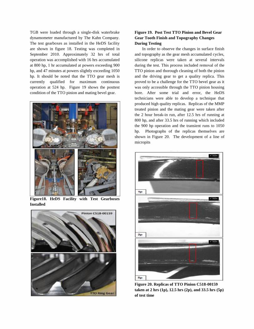
TGB were loaded through a single-disk waterbrake
dynamometer manufactured by The Kahn Company.
The test gearboxes as installed in the HeDS facility
are shown in figure 18. Testing was completed in
September 2010. Approximately 32 hrs of total
operation was accomplished with 16 hrs accumulated
at 800 hp, 1 hr accumulated at powers exceeding 900
hp, and 47 minutes at powers slightly exceeding 1050
hp. It should be noted that the TTO gear mesh is
currently qualified for maximum continuous
operation at 524 hp. Figure 19 shows the posttest
condition of the TTO pinion and mating bevel gear.
Figure18. HeDS Facility with Test Gearboxes
Installed
Figure 19. Post Test TTO Pinion and Bevel Gear
Gear Tooth Finish and Topography Changes
During Testing
In order to observe the changes in surface finish
and topography as the gear mesh accumulated cycles,
silicone replicas were taken at several intervals
during the test. This process included removal of the
TTO pinion and thorough cleaning of both the pinion
and the driving gear to get a quality replica. This
proved to be a challenge for the TTO bevel gear as it
was only accessible through the TTO pinion housing
bore. After some trial and error, the HeDS
technicians were able to develop a technique that
produced high quality replicas. Replicas of the MMP
treated pinion and the mating gear were taken after
the 2 hour break-in run, after 12.5 hrs of running at
800 hp, and after 33.5 hrs of running which included
the 900 hp operation and the transient runs to 1050
hp. Photographs of the replicas themselves are
shown in Figure 20. The development of a line of
micropits
Figure 20. Replicas of TTO Pinion C518-00159
taken at 2 hrs (1p), 12.5 hrs (2p), and 33.5 hrs (5p)
of test time
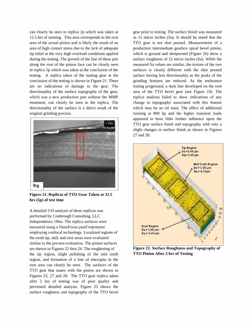
can clearly be seen in replica 2p which was taken at
12.5 hrs of running. This area corresponds to the root
area of the actual pinion and is likely the result of an
area of high contact stress due to the lack of adequate
tip relief at the very high overload conditions applied
during the testing. The growth of the line of these pits
along the root of the pinion face can be clearly seen
in replica 5p which was taken at the conclusion of the
testing. A replica taken of the mating gear at the
conclusion of the testing is shown in Figure 21. There
are no indications of damage to the gear. The
directionality of the surface topography of the gear,
which was a new production part without the MMP
treatment, can clearly be seen in the replica. The
directionality of the surface is a direct result of the
original grinding process.
Figure 21. Replicas of TTO Gear Taken at 33.5
hrs (5p) of test time
A detailed 3-D analysis of these replicas was
performed by Coubrough Consulting, LLC
Independence, Ohio. The replica surfaces were
measured using a NanoFocus μsurf topometer
employing confocal technology. Localized regions of
the tooth tip, mid, and root areas were evaluated
similar to the pre-test evaluation. The pinion surfaces
are shown in Figures 22 thru 24. The roughening of
the tip region, slight polishing of the mid tooth
region, and formation of a line of micropits in the
root area can clearly be seen. The surfaces of the
TTO gear that mates with the pinion are shown in
Figures 25, 27 and 28. The TTO gear replica taken
after 2 hrs of testing was of poor quality and
prevented detailed analysis. Figure 25 shows the
surface roughness and topography of the TTO bevel
gear prior to testing. The surface finish was measured
as 15 micro inches (Sa). It should be noted that the
TTO gear is not shot peened. Measurements of a
production intermediate gearbox spiral bevel pinion,
which is ground and shotpeened (Figure 26) show a
surface roughness of 12 micro inches (Sa). While the
measured Sa values are similar, the texture of the two
surfaces is clearly different with the shot peened
surface having less directionality as the peaks of the
grinding features are reduced. As the endurance
testing progressed, a dark line developed on the root
area of the TTO bevel gear (see Figure 19). The
replica analysis failed to show indications of any
change in topography associated with this feature
which may be an oil stain. The effect of additional
running at 800 hp and the higher transient loads
appeared to have little further influence upon the
TTO gear surface finish and topography with only a
slight changes in surface finish as shown in Figures
27 and 28.
Figure 22. Surface Roughness and Topography of
TTO Pinion After 2 hrs of Testing
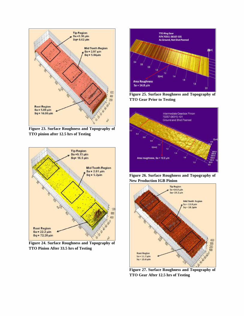
Figure 23. Surface Roughness and Topography of
TTO pinion after 12.5 hrs of Testing
Figure 24. Surface Roughness and Topography of
TTO Pinion After 33.5 hrs of Testing
Figure 25. Surface Roughness and Topography of
TTO Gear Prior to Testing
Figure 26. Surface Roughness and Topography of
New Production IGB Pinion
Figure 27. Surface Roughness and Topography of
TTO Gear After 12.5 hrs of Testing
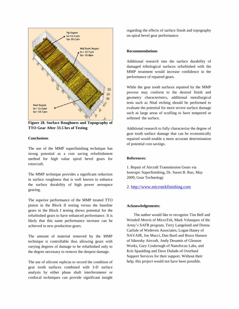
Figure 28. Surface Roughness and Topography of
TTO Gear After 33.5 hrs of Testing
Conclusions
The use of the MMP superfinishing technique has
strong potential as a cost saving refurbishment
method for high value spiral bevel gears for
rotorcraft.
The MMP technique provides a significant reduction
in surface roughness that is well known to enhance
the surface durability of high power aerospace
gearing.
The superior performance of the MMP treated TTO
pinion in the Block II testing versus the baseline
gears in the Block I testing shows potential for the
refurbished gears to have enhanced performance. It is
likely that this same performance increase can be
achieved in new production gears.
The amount of material removed by the MMP
technique is controllable thus allowing gears with
varying degrees of damage to be refurbished only to
the degree necessary to remove the deepest damage.
The use of silicone replicas to record the condition of
gear tooth surfaces combined with 3-D surface
analysis by either phase shaft interferometer or
confocal techniques can provide significant insight
regarding the effects of surface finish and topography
on spiral bevel gear performance.
Recommendations
Additional research into the surface durability of
damaged tribological surfaces refurbished with the
MMP treatment would increase confidence in the
performance of repaired gears.
While the gear tooth surfaces repaired by the MMP
process may conform to the desired finish and
geometry characteristics, additional metallurgical
tests such as Nital etching should be performed to
evaluate the potential for more severe surface damage
such as large areas of scuffing to have tempered or
softened the surface.
Additional research to fully characterize the degree of
gear tooth surface damage that can be economically
repaired would enable a more accurate determination
of potential cost savings.
References:
1. Repair of Aircraft Transmission Gears via
Isotropic Superfinishing, Dr. Suren B. Rao, May
2009, Gear Technology
2. http://www.microtekfinishing.com
Acknowledgements:
The author would like to recognize Tim Bell and
Wendell Morris of MicroTek, Mark Velasquez of the
Army’s SAFR program, Terry Langeland and Donna
Carlisle of Wedeven Associates, Logan Haney of
NAVAIR, Joe Mucci, Dan Bartl and Bruce Hansen
of Sikorsky Aircraft, Andy Desantis of Gleason
Works, Gary Coubrough of Nanofocus Labs, and
Kris Spaulding and Dave Dulude of Overhaul
Support Services for their support. Without their
help, this project would not have been possible.