Embed Size (px)
Citation preview
WISCONSINMODEL W4-1770
REPAIR
WIS-CONTOTAL POWER CORP.

FOREWORD
Good operation and a planned maintenance program as outlined in this manual are vital inobtaining maximum engine performance and long engine life. The instructions on the followingpages have been written with this in mind, to give the operator a better understanding of thevarious problems which may arise, and the manner in which these problems can best be solvedor avoided.
The operator is cautioned against the use of any parts, other than genuine Wis-Con Total Powerparts, for replacement or repair. These parts have been engineered and tested for theirparticular job, and the use of any other parts may result in unsatisfactory performance and shortengine life. Wis-Con Total Power distributors and dealers, because of their close factoryrelations, can render the best and most efficient service.
THE LIFE OF YOUR ENGINE DEPENDS ON THE CARE IT RECEIVES.
The MODEL, SPECIFICATION and SERIAL NUMBER of your engine must be given whenordering parts. The MODEL and SPECIFICATION number are on the name plate. The SERIALNUMBER is stamped either on the crankcase or the engine’s identification tag.
Copy the MODEL, SPECIFICATION and SERIAL NUMBER in the spaces provided below sothat it will be available when ordering parts.
MODEL SPECIFICATION
SERIAL NUMBER
To insure prompt and accurate service, the following information must also be given:
1. State EXACTLY the quantity of each part and part number.
2. State definitely whether parts are to be shipped by express, freight or parcel post.
3. State the exact mailing address.

IMPORTANT
READ THESE INSTRUCTIONS CAREFULLY
All points of operation and maintenance have been covered as carefully as possible, but if furtherinformation is required, send inquiries to the factory for prompt attention.
When writing to the factory, ALWAYS GIVE THE MODEL, SPECIFICATION AND SERIALNUMBER of the engine referred to.
Startincj and O.Deratinq New En~aines
Careful breaking-in of a new engine will greatly increase its life and resu It in troublefree operation.A factory test is not sufficient to establish the polished bearing surfaces, which are so necessaryto the proper performance and long life of an engine. These can only be obtained by running anew engine carefully and under reduced loads for a short time.
¯ Be sure the engine is filled to the proper level with a good quality engine oil.
¯ For proper procedures to follow when breaking-in a new engine, see ’Testing Rebuilt Engine’.
The various bearing surfaces in a new engine have not been glazed, as they will be with continuedoperation, and it is i~ this period of "running in" that special care must be exercised, otherwisethe highly desired glaze will never be obtained. A new bearing surface that has once beendamaged by carelessness will be ruined forever.

IMP()RTAN SAFETY NOTICE
Proper repair is important to the safe and reliable operation of an engine. This Repair Manualoutlines basic recommended procedures, some of which require special tools, devices or workmethods.
Improper repair procedures can be dangerous and could result in injury or death.
READ AND UNDERSTAND ALL SAFETY PRECAUTIONS ANDWARNINGS BEFORE PERFORMING REPAIRS ON THIS ENGINE
Warning labels have also been put on the engines to provide instructions and identify specifichazards which, if not heeded, could cause bodily injury ordeath to you or other persons. Theselabels identify hazards which may not be apparent to a trained mechanic. There are manypotential hazards for an untrained mechanic and there is no way to label the engine against allsuch hazards. These warnings in the Repair Manual and on the engine are identified by thissymbol:
Operations that may result only in engine damage are identified in the Repair Manual by thissymbol:
CAUTIONWis-Con Total Power cannot anticipate every possible circumstance that might involve apotential hazard; therefore, the warnings in this manual are not all inclusive. If a procedure,tool, device or work method not specifically recommended by Wis-Con Total Power, IndustrialProduct Division is used, you must satisfy yourself that it is safe for you and others. You shouldalso ensure that the engine will not be damaged or made unsafe by the procedures you choose.
IMPORTANT: The information, specifications and illustrations in this manual are basedon information that was available at the time it was published. The specifications,torques, pressures of operation, measurements, adjustments, illustrations and otheritems can change at any time. These changes can affect the service given to the product.Get the complete and most current information before starting any job. For parts,service, or information, contact Wis-Con Total Power, Memphis, Tennessee.

/ WARNINGMost sub-systems used in conjunction with Wis-Con Total Power industrial engines including(but not limited to) radiators, hoses, fans, fuel tanks, fuel lines or other fuel system components,batteries, electrical connections or other electrical components, clutches, transmissions,hydraulic pumps and generators, are not supplied by Wis-Con Total Power. These items areprovided by the manufacturer of the end item in which the engine is used.
Some of the dangers associated with servicing such items are generally mentioned in thismanual; however, the appropriate handbooks and safety instructions provided by the manufac-turer of the end item should always be consulted prior to the undertaking of any work on sub-systems attached to the engine, to avoid any hazards inherent to these sub-systems.
WARNINGRead and observe all individual safety warnings as you use this manual to operate, service orrepair your engine.
Always exercise caution whenever working with an engine or any associated system.
Injuries may be caused by lack of care when working with, or near, moving parts, hot parts,pressurized systems, electrical equipment, or fuel systems.
Always wear eye and hearing protection when working on or near engines.
Improper attire such as loose clothing, ties, rings, soft shoes or bare feet could bi~ hazardous andshould be avoided when servicing engines.
Use or service of the engine (including the use of modified parts or materials) not in accordancewith manufacturer’s specifications could damage your engine or cause personal injury.
Some equipment and materials used in the overhaul or maintenance of an engine such asmachine tools, electrical equipment, compressed air, solvents, gasoline or other fuels may bedangerous and can cause injury. Always observe safety precautions.
III

CONTENTS
Accessories - Service Instructions ....................................... 35Fuel PumpCarburetorMagneto
Adjusunents ...........................................................................9Carburetor ........................................................................9Clutch Adjustment ........................................................... 9Clutch Reduction Adjustment ........................................ 10Distributor - Breaker Point ............................................. 10Governor Adjustment ..................................................... 11Magneto - Breaker Point ................................................ l 1Valve Tappet ..................................................................12
Before Starting Engine .......................................................... 5Belt Driven Alternator ......................................................... 19Charging System ....................................................................5Clutch .....................................................................................9Clutch Reduction .................................................................10Cooling ..................................................................................5Disassembly and Reassembly - Safety Notice .................... 23
Accessories ....................................................................23Air Cleaner ......................................................................23Air Shrouding ..................................................................24Camshaft Gear ................................................................27Camshaft and Valve Tappets ......................................... 33Connecting Rods and Pistons ....................... 2: ...............29Control Panel .................................................................23Cylinder Blocks .............................................................31Cylinder Heads ...............................................................25Distributor and Accessory Drive ................................... 25End Play .........................................................................33Engine Support and Oil Pan ........................................... 28Flywheel .........................................................................24Flywheel Alternator .... ~ ..................................................26
mFuel Pu p ......................................................................25Gear Cover .....................................................................27Gear Train ......................................................................28Governor ........................................................................26Idler Gear and Shaft .......................................................27Main Bearing Plate and Crankshaft ................................ 32Manifold and Carburetor ................................................ 25Oil Filter .........................................................................Oil Pump .........................................................................28Outboard, 3rd Main Bearing .......................................... 27Piston Rings ...................................................................30Shell Bearings ................................................................29Starting Motor ................................................................Tool Requirements ......................................................... 23Valves and Seat Inserts .................................................. 31Valve Springs - Rotators-Guide ............................... 31, 32
Electrical Equipment ............................................................15Flywheel Alternator ....................................................... 15Wiring Circuit ................................................................16Wiring Diagrams ...................................................... 16, 20
Flywheel Alternator - Service Procedure ............................ 16Rectifier Tests ................................................................18
Regulator Tests ..............................................................17Static Tests .....................................................................18Stator Tests .....................................................................18Trouble Shooting ...........................................................16
Fuel ........................................................................................5General Information and Design ........................................... 5Governor -- Operation ........................................................ 10Horsepower ............................................................................2Illustration of Engine .............................................................3Lubrication System -- Description ....................................... 5Lubrication System -- Illustration ........................................ 4Maintenance Schedule ......................................................... 42Maintenance ...........................................................................7
Air Cleaners .....................................................................7Breather System ...............................................................8Crankcase Oil ...................................................................8Fuel Filter .........................................................................8Ignition Distributor ..........................................................8Kccp Engine Clean .......................................................... 9Oil Filter ...........................................................................8PCV System .....................................................................8Prc-Cleaner ......................................................................7Spark Plugs ......................................................................9Starting Motor ..................................................................9
Oil - Grade of .........................................................................5Oil Pressure ............................................................................5Rotation .................................................................................5Safety Precautions .................................................................2Solid State Ignition Distributors ...................................... 8, 43Specifications .........................................................................2Starting Procedure .................................................................6Stopping Engine ....................................................................7Storage of Engine for Winter ............................................... 34Temperature Safety Switch .................................................. 20Testing Rebuilt Engine ........................................................ 34Timing .................................................................................12
Distributor Timing ......................................................... 12Firing Order ...................................................................12Magneto Timing ............................................................. 14Timing Check .................................................................13
Torque Specification, Std. hardware ................................... 42Troubles - Causes and Remedies ......................................... 20
Backfiring Through Carburetor ..................................... 22Compression ..................................................................21Fuel Mixture ..................................................................21Ignition ...........................................................................21Ignition Spark .................................................................22Knot:Icing ........................................................................22Missing ...........................................................................21Overheating ....................................................................22Starting Difficulties ........................................................21Stops ...............................................................................21Surging or Galloping ...................................................... 22
Warm-Up Period ....................................................................6

SPECIFICATIONS
MODEL W4-1770
Bore ........................................................... 3.25 inchStroke ........................................................ 3.25 inchPiston Displacement -cu. in .................. 107.7
-cu. cm ................ 1765.2Horsepower - 1400 R.P.M ........................ 18.2
1600 R.P.M ........................ 21.31800 R.P.M ........................ 24.22000 R.P.M ........................ 27.12200 R.P.M ........................ 29.62400 R.P.M ........................ 32.02600 R.P.M ........................ 33.62800 R.P.M ........................ 34.63000 R.P.M ........................ 35.0
Engine rated performance is documented toEngine Test Code - SAE J1349.
Continuous duty operation is recommended at 80% of horsepowershown.
Horsepower specified in the accompanying chart is for an atmo-spheric temperature of 77% Fahrenheit and at a Barometric pressureof 29.52 inches of mercury.
For each inch lower the Barometric pressure drops, there willbe a lossin horsepower of 3 1/2%.
For each 10° temperature rise there will be a reduction in horsepowerof 1%.
For each 1000 ft. altitude above sea level there will be a reduction inhorsepower of 3 I/2%.
The friction in new engines cannot be reduced to the ultLmateminimum during the regular block test, but engines axe guaranteed todevelop at least 85 percent of maximum power when shipped from thefactory. The power will increase as friction is reduced during the fastfew days of operation. The engine will develop at least 95% ofmaximum horsepower when friction is reduced to a minimum.
SAFETY PRECAUTIONS
Careless use ofthe engine causes a high percentge of accidents. Avoid serious injury by being alert, use common sense and be safetyminded. Observe the following pecautions and carefully enforce them when operating your Wisconsin Engine. Read operatingintructions thoroughly - Know how to stop the engine in case of emergency.
A This symbol indicates important safety messages throughout this Repair Manual -Read Them Carefully.
¯ Engine should be operated only by qualified persons.
¯ Do not operate engine in a closed building unless the exhaust ispiped outside. This exhaust contains carbon monoxide, a posionous,odorless and invisible gas, which if breathed can cause serious illnessand possible death.
¯ Keep exhaust connection tight and components in good condition;noise from a faulty echaust system can also be harmful.
¯ Exhaust system parts get very hot - avoid touching these parts untilthe engine has stopped and has sufficiently cooled off.
¯ Never refuel a hot or rurming engine. Do not smoke while filling fueltank or servicing fuel system.
¯ ,Always refuel slowly to avoid spillage.
¯ Make sure all fuel lines and connections are tight and in goodcondition.
¯ Handle batteries carefully; battery acid will bum skin and can causeblindess if it contacts the eyes.
¯ Avoid sparks near battery. Gas Given off by battery is explosive.
¯ Keep engine and surrounding area clean and clear of trash.
¯ When starting engine maintain a safe d~stance from movmg parts ofequipment. Be sure all rotating parts are secure and in good condition.
¯ Do not start engine with clutch engaged.
¯ Never run engine with governor linkage disconnected, or operate atspeeds in excess of 3000 R.P.M. load.
¯ Never make adjustments on machinery while it is connected to theengine, without first disconnecting the ignition cables from the sparkplugs. Turning the machinery over by hand during adjusting orcleaning might start the engine and machinery with it, causing seriousinjury to the operator.
¯ Never run engine while safety switches are disconnected, or protec-five screening is removed from unit.
¯ Do not leave engine nmning while lubricating, making adjustmentsor repairs unless specifically recommended.
¯ Never leave engine unattended while it is running.
¯ Keep hands, feet and clothing away from all moving parts.
¯ Mount a fire extinguisher close to the engine. Maintain extinguisherproperly and be familiar with its use.
¯ Precaution is the best insurance against accidents.
2

SPARK PLUGS
VALVEINSPECTIONCOVERS
STARTINGSOLENOID
IXHAUST MUFFLER
FUEL PUMP
FUEL FILTER
OIL FILLERBREATHER CAP
FUEL SHUT.OFF VALVE
Flywheel Alternator
RECTIFIER
REGULATOR
STARTINGMOTOR
TAKE-OFF SHAFTf
Take-off End-H;ew
IGNITION COIL
OIL DIPSTICK
OIL FILTER
OIL DRAIN PLUG
CARBURETOR
GOVERNOR LEVER
CYLINDERNUMBERS
AMMETER
CHOKE BUTTON
STARTER
PRE-CLEANER
AIR CLEANER
IGNITIONDISTRIBUTOR
IGNITION SWITCH
TIMING CHECK OPENING
Flywheel End View
VARIABLE SPEED CONTROL
FLYWHEEL SHROUD
MODEL
Fig. 1
W4-1770 AIR COOLED ENGINE
3 M1-1182
r
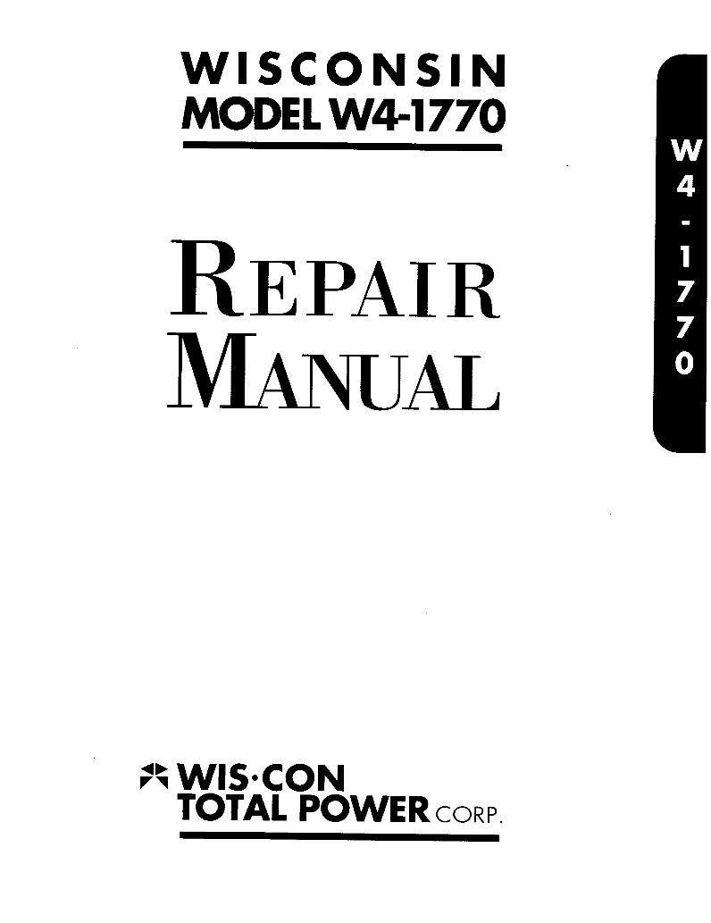
THIRD MAIN BEARING
NOTE:CYLINDERS, RINGS, PISTONS, PINS, TAPPETS, VALVES,CAMSHAFT, BEARINGS AND ETC. ARE LUBRICATED BYTHE OIL SPRAY OR MIST THROWN OFF THE CONNECT-ING RODS AND CRANKSHAFT.
OIL SPRAY NOZZLE~
MAIN ROLLER"-- BEARING
STANDARD LOCATIONOF OIL DIPSTICK
OIL STRAINER
MAIN ROLLERBEARING
OIL PRESSURE RELIEF VALVESET FOR 15 POUNDS PRESSURE
OPTIONAL LOCATIONOF OIL DIPSTICK
FULL AND LOW MARKSON OIL DIPSTICK
OIL PUMP
OIL HEADER TUBESTRAINER SCREEN
OIL RETURN FROMFILTER INTO CRANKCASE
WITH ENGINE AT OPERATING TEMPERATURE, OIL PRESSUREIN HEADER WILL BE APPROXIMATELY ,5 POUNDS.
OIL FILLER ANDBREATHER CAP
OIL FILTER
OIL LINE TOGOVERNOR
OIL DRAIN PLUG

GENERAL INFORMATION and DESIGN GOVERNOR
Wisconsin engines are of the four cycle type, in which eachof the four operations of suction, compression, xpansionandsxhaustrequires a complete stroke. This gives one powerstroke per cylinder for each two revolutions of the crankshaft.
COOUNG
Cooling is accomplished by a flow of air, circulated over thecylinders and heads of the engine, by a combination fan-fly-wheel encased in a sheet metal shroud. The air is divided anddirected by ducts and baffle plates to insure uniform cooling ofall parts.
Never operate an engine with any part of theshrouding rernovedmthis will retard air cooling.
Keep the cylinder and head fins free from dirt andchaff. Improper circulation of cooling air will causeengine to overheat.
CARBURETOR
The proper combustible mixture of gasoline and air is fur-nished by a balanced carburetor, with a fixed main metering jet,that provides correct fuel to air ratios for all speeds and loads.
IGNITION SYSTEM
The spark for ignition of the fuel mixture is directed from thecoil to the spark plugs, at the proper time, by Battery ignition(12 volt) Distributor.
Magneto ignition can be furnished in place of distributor,when specified. The high tension magneto used, is fitted withan impulse coupling that provides a powerful spark for easystarting.
CHARGING SYSTEM
Engines can be equipped with a l0 amp, 25 amp, or 30 ampflywheel alternator system or a 37 amp belt driven alternator.
LUBRICATION SYSTEM, Fig. 2
A gear type pump supplies oil to four nozzles which direct oilstreams against fins on the connecting rod caps. Part of the oilenters the rod bearing through holes in the rods, and the balanceof the oil forms a spray or mist which lubricates the cylinderwalls and other internal parts of the engine. An external oil linefrom the oil header tube in the crankcase lubricates the gover-nor and gear train.
OIL PRESSURE
At engine operating temperature the oil pressure will be about4 to 5 pounds per square inch. Due to this low pressure systeman Oil Pressure Gauge is not furnished as standard equipmentbut is optionally available, along with Low Oil Pressure andHigh Temperature Shut-off Switches. When engine is cold theoil pressure will be higher than 4 to 5 pounds. Under thiscondition, a relief valve in the oil pump limits the pressure toa maximum of 15 p.s.i.
A governor of the centrifugal flyweight type maintains theengine speed by varying the throttle opening to suit the loadimposed upon the engine. These engines are equipped witheither a fixed speed governor, a variable speed contraltoregulate the governed speed of the engine, or an idle control.
ROTATION
The rotation at~ the crankshaft is clockwise when viewing theflywheel or cranking end of the engine. This gives counter-clockwise rotation when viewing the power take-offend of thecrankshaft. The flywheel end of the engine is designated the frontend, and the power take.off end, the rear end of the engine.
BEFORE STARTING ENGINE
I. FUEL
Fill fuel tank with a reputable well known brand of RegularGrade gasoline. Leaded gasoline is pr¢ferred with an *Anti-knock Index of 87minimum. Unleaded regular gasoline may beused, although shorter valve life may be experienced.Note: *minimum Motor octane number must be 82.
~ Caution: Refuel slowly to avoid spillage. Do not smokewhen filling tank.
Be sure that vent hole in fuel tank cap is clean and free of anyobstruction.
2. LUBRICATION
Fill crankcase base with the proper grade of engine oil asspecified in "Grade Of Oil"chart. Fill through the oil filler tubeopening to the level indicated by the Full Mark on Dipstick.Approximately 3 1/2 quarts are required in a new engine -- 4quarts with oil and filter change.
IMPORTANT
Do Not overfill crankcase. DO Not allow oil level to go belowAdd mark on dip stick.
GRADE OF OIL
SEASON OR TEMPERATURE I GRADE OF 01L.
Spring, Summer or Fall
+ 120°F to + 40°F I SAE 30
Win~’er+ 40°F to + 15°F SAE 20-20W+ 15°F to 0°F SAE 10WBelow Zero SAE 5W-20
Use Oils classified as Service SE, SF, SG or CCNew engine 4 Qts.
Crankcase Oil and filter change 4 Qts.Capa c i tyLess - Filter or filter change 3~/2 Qts.
I.f engine is used at near maximum performance, it is recom-mended that a single-viscosity oil of SE Quality be used; eithergrade SAE 30 or SAE 10W.

FILL THRUINSPECTIONOPENING
OIL LEVEL PLUG~
OIL DRAIN PLUG
Fig. 3
FILL THRUINSPECTIONOPENING
OIL LEVEL
OIL DRAIN PLUG
Fig. 4
Proven synthetic oils give superior service in aircooled gasoline engines and can be used, but therecommended oil change interval remains at 100hours.With reference to Fig. 3 and Fig. ~/, fill clutch andgear reduction units to the height of the oil levelplug opening - Use same grade oil as used inengine crankcase. Add sufficient oil betweenchanges to keep oil up to the level plug opening.
Change Oil In Clutch and Reduction Units atleast every 500 hours of operation.
STARTING
A Caution: Maintain a safe distance from movingparts of equipment. Know how to stop theengine quickly in case of emergency.
A Caution: Do not operate engine in a closedbuilding unless it is properly ventilated.
STARTING PROCEDURE, Fig. 5
I. Check crankcase oil level and gasoline supply.Open fuel shut-off valve in fuel strainer or tank.
2. Disengage clutch, if furnished.
3. Pull variable speed control ’T’ handle out abouthalf-way and lock in place. With a two speed con-trol, start in full load position - _;dle after enginestarts.
AMMETER
CHOKE
IGNITION SWITCH
STARTER
SPEED CONTROL
WITHOUT SOLENOID STARTING
CHOKE BUTTON
STARTER BUTTON
AMMETER
IGNITION SWITCH
SPEED CONTROL
..... WITH SOLENOID STARTINGFig. S, CONTROL PANELS
4. Close choke by pulling choke button to extremeout position.
5. Pull out ignition switch button, tag reads ’ToStop Push In’.
6. Depress starter switch to start engine.
IMPORTANT
Do not crank engine for more then 30 seconds ata time if engine fails to start, wait about 2 minutesbetween cranking periods to prevent starter fromover-heating.
7. After engine starts, push choke button in graduallyas required for smooth running. Choke must be com-pletely open(button in)when engine is warmed up.
If flooding should occur, open choke fully by pushingchoke button in and continue cranking. Less chokingis necessary in warm weather or when engine is warm,than when cold.
WARM.UPAfter engine starts, allow it to warm up a few minutesbefore applying load. Do not race or gun engine tohurry WARM-UP. The proper oil film on various sur-faces of the pistons, cylinders, bearings, etc., cannotbe established until the oil has warmed up and becomesufficiently fluid.
A Caution: Racing an engine by disconnecting thegovernor, or by doing anything to interfere withthe governor controlled engine speed, is extremelydangerous.
The governor is provided as a means for controllingthe engine speed to suit the load applied, and also asa safety measure to guard against excessive speeds,which not only overstrain all working parts, but whichmight cause wrecking of the engine and possible in-jury to bystanders.

TO STOP ENOINE
Depress ignition switch button, tag reads ’To StopPush In’.
If engine has been running hard and is hot, do notstop it abruptly from full load. Cool the engine byremoving the load and allowing the engine to run idle(1000 to 1200 R.P.M.), fo~ 3 to 5 minutes.
Magneto ignition engines have a lever type stop switchon the side of the magneto. On these, to stop engine,depress lever and hold down until engine stops.
~.AINTENANCE
AIR CLEANERS
The air cleaner is an essential accessory, filteringthe air entering the carburetor and preventing abrasivedirt from entering the engine and wearing out valvesand piston rings in a very short time.
The air cleaner must be serviced frequently, depend-ing on the dust: conditions in which the engine isoperated. Check hose connections for leaks or breaksand replace all broken or damaged hose clamps.
Excessive smoke or loss of power are good indicationsthat the air cleaner requires attention.
OIL BATH AIR CLEANER Fig. 6
Service Daily; or twice a day if engine is operatingin very dusty conditions. Once each week; in com-paratively clean conditions.
Remove oil cup from bottom of air cleaner and cleanthoroughly. Add the same grade of oil, as used in theengine c.rankcase, to the Level Line indicated on theoil cup.
LECTOR TYPEPRE-CLEANER
OIL BATHHOSE CONNECTIONS ...... AIR CLEANER
/
OIL CUP
OIL LEVEL
Fig. 6 OIL BATH AIR CLEANER
DUSTUNLOADER
Fig. 7 DRY TYPE AIR CLEANER
IMPORTANT
Operating the engine under dusty conditions withoutoil in the air cleaner or with dirty oil, may wear outcylinders, pistons, rings and bearings in just a fewdays time.
Once o Year; or oftener if conditions are severe, theair cleaner should be removed from the engine and theelement, which is not removable, should be washedin a solvent to clean out accumulated dust and dirt.
DRY TYPE AIR CLEANER, Fig. 7
Service Doily; squeeze rubber dust unloader once ortwice a day to check for possible obstruction. Ifengine is operating in very dusty conditions, removecartridge and shake out the accumulated dirt (do nottap or strike element - it may become damaged). Wipeout dirt from inside cover and bowl, after removingbaffle and dumping out dust.
Once Each Week; The filtering cartridge should betaken out and rinsed under a. faucet with cold water,then wash by repeated dippings for several minutesin a solution of lukewarm water and a mild, Non-sudsing detergent. Rinse in cold water from the insideout, and allow to dry over-night before re-installing.In cold weather, protect element from freezing until dry.
Do Not Use Gasoline, Kerosene or Solvent For Clean-ing - Do Not Oil Element.
After ten washings or one year of service, replacecartridge. New cartridges are available at all Wis-consin Distributors and Service Centers.
PRE-CL EANER
The optionally furnished collector type pre-cleaner,mounted to the top of the air cleaner as illustrated inFig. 7, removes the larger dirt and dust particles be-fore the air reaches the main air cleaner.
Clean bowl regularly of accumulated dust and dirt. Donot put oil or water in pre-cleaner, this must be kept dry.

Caution: Wear gloves when removing drain plug fromCARBURETOR A hot engine.
IMPORTANT
FILTER / ~L ’~ H.li FILLER CAPII Refer to Recommended Grades of Oil chart, PageS, for
I~II ! "’~-~==~ )I
type and quantity of oil to be used.
I~. ~--~-~.., ,~~"-.~/--~/~OIL FILTER, Fig. 1
! "~,’/",~,, L~ \1 Abyo/~sstypeoilfil~risfurnishedasstandardequipmenton
! !~ ~" . . \1 this model engine, except in a few cases when the use of other
//~/~i’~
I
location.aCcess°ries interferes with the standard oil filter mounting
.. .... Every Other 08 Chsng~, replace filter cartridge. If operat-
OPERA~O~
FILTERED AIRBLOW-BY GASESBLOW-BY AND FILTERED AIR MIXTURECOMBUSTIBLE FUEL VAPOR
F~g. B
BREATHER SYSTEM
The crankcase is ventilated thru a breather capmounted to the top of the oil filler tube, as illustratedin Fig. 2. At every oil chan~e, it is recommended thatthe cap be cleaned by washing in kerosene.
PCV SYSTEM, Fig. 8
If engine is optionally equipped with a positive crank-case ventilation (PCV) system: Every 50 Hours; washair intake filter element in a solution of hot water andnon-sudsing detergent.
Service Filter Daily; if engine is operating in extremedust and dirty conditions.
Every 500 Hours; clean PCV valve with carburetorsolvent or lacquer thinner.
Indications of Dirty or Faulty PCV valve are:
1. Excessive slug in or around engine.
2. Excessive smoke from crankcase Filter.
3. Excessive crankcase vacuum (over 2" H20).
4. Poor or rough idling.
CRANKCASE OIL
Check Oil Level Every 8 Hours. One quart of oil isrequired to raise the oil level from Add to Full markon dipstick.
Chan~e Oil Every I00 Hours under normal operatingconditions. In extreme dusty and extensive idlingcon-ditions, change oil at 50 hour intervals. Remove drainplug and allow oil to drain into a suitable container.Drain oil while engine is hot- it ~¢ii1 flow more freely.
ing conditions are extremely dusty, replace cartridge at everyoil change. Use only Wisconsin Miero-Fin~ Oil filter car-tridges available from your local Wis-Con Total Power Dis-tributor or Service Center.
BAIL NUT
SCREEN
GASKET~
GLASSBOWL
Fig. 9
FUEL FILTER, Fig. 9
It is very important that the fuel be filtered to prevent sediment,dirt and water from entering the carburetor and causing troubleor even complete stoppage of the engine. The glass filter bowlshould be inspected frequently, and cleaned if dirt or water arepresent.
To remove sediment bowl, loosen nut below bowl, swing bailto one side and twist bowl as it is being removed. Clean screenand bowl thoroughly - replace gasket if it is damaged orhardened. Repair Kits are avilable for service replacement.
IGNITION DISTRIBUTOR, Fig. 14
Check for faulty and loose fitting wires, and for cracks in
distributor cap.
SOLID STATE IGNITION DISTRIBUTORS
Many Wisconsin engines are now being equipped with a solidstate ignition distributor. Detailed troubleshooting and repairinformation can be found in the rear section of this manual. Forrepair parts, see your W4-1770 Illustrated Parts Catalog.
8

,SET GAP
WIRE GAUGE
Fig. I0
SPARK PLUGS, Fig. 10
Incorrect gap, fouled or worn spark plug electrodes,will have an adverse affect on engine operation.
Every 250 Hours; remove spark plugs - clean, regapor replace if necessary.
Spark plug gap - 0.030 inch
Replacement plugs must be of the correct heat range,like Champion No. D-16], AC No. C 86 Commercial,
(Wisconsin YD- 6). Thread size is 18ram. In reassem-bly tighten spark plugs, 25 to 30 foot pounds torque.
STARTING MOTOR, Fig. 1
No maintenance is required other than keeping theoutside of the starting motor clean, and periodic in-spection for insecure mounting and loose or corrodedcable connections.
In extreme dust and dirt conditions it may be necessaryto occasionally remove the starter from the engineand clean the Bendix by brushing with Kerosene. Donot oil Bendix drive - if necessary lubricate withpowdered graphite. ~
CYLINDER and HEAD COVERSRemove and scrape dirt fromcylinder and head fins.
AIR INTAK ERemove screen
VEE AREA and brush clean.Remove dirt and chaff from manifoldports and space between CYL. blocks.
Fig. 11
KEEP ENGINE CLEAN, Fig. 11
This engine is coo’led by blasts of air which must beallowed to circulate all around the cylinders andcylinder heads to properly cool the engine and there-by keep it in good running condition. If dust, dirt orchaff is allowed to collect in the cylinder shroudingor in the V between the cylinders, it will retard" theflow of air and cause the engine to overheat. Keepflywheel screen clean, so as not to restrict the intakeof cooling air.
IMPORTANT
Do Not operate engine with damaged or badly dentedshrouding.
Do Not operate engine with any part of the shroudingremoved. This will retard air cooling.
ADJU STM ENTS
CARBURETORThe carburetor Main Metering Jet is of the fixed typeand therefore no adjustment is necessary.
The correct amount of throttle plate opening for theproper low idle speed is obtained by means of theThrottle Stop Screw. However, this is set at thefactory so that no immediate adjustment is necessary.The Idle Adjustment is for smooth low speed operationand this adjustment, if necessary, must be made withthe engine running at idle speed (throttle valveclosed). Initial setting is approximately 1~,2 turn $ open.
Refer to ’C:IRBURE 7t)R’ section, Page 37, for furtherAdjustment and Repair Information.
CLUTCH ADJUSTMENT, Fig. 12
If the clutch begins to slip, it should be re-adjustedto prevent it from becoming over-heated and damaged.First, remove inspection plate to expose the adjustingring. Release clutch by pushing shifter lever forwardtoward en ~ine).
ADLOCKSCREW
ADJUSTMENTLOCK
ADJUSTING RING(TURN IN CLOCK-WISE DIRECTION)
CLUTCHENGAGING LEVER
tRELEASED POSITION)
Fig. 12
9 M1-1188

ENGAGING LEVER ~(Released Position)
-OPTIONAL- ADJUSTMENTADJUSTING PLU~ f LOCKSCREW
/(Opt o =10penin~i/on Opposite Side)
ADJUSTING LOCK
NOTCHES ON ~ADJUSTING RING.’
Fig. 13
Turn ngine over until clutch adjustment lock isvisible thin the inspection opening. Loosen odiust.ment Iockscrew one full turn. Keep clutch from turningby securing the crankshaft at flywheel end. Then, bymeans of a screw driver, turn adjusting ring one notchat a time in a clockwise direction, until a very firmpressure is required when engaging the clutch shifterlever, and as the clutch snaps into engaged position.Securely tighten adjustment lockscrewL Assemble in-spection plate, being sure that the gasket fits proper-ly and is not broken.
CLUTCH REDUCTION ADJUSTMENT, Fig. 13
The clutch in the clutch reduction unit is the sameas used in the power take-off unit and is adjusted thrutwo pipe tap openings; one for the adjustment lock.screw and the other for turning the adjusting ring.There are four adjusting plugs in the housing to pro-vide a means of adjusting the clutch regardless ofwhat position the unit is mounted in.
Remove the two pipe plugs on the side of the housing(if not accessible, use the two optional taps). Dis-engage the clutch and turn engine over slowly with ahand crank until the adjustment Iockscrew is visiblethru the pipe plug opening nearest to the engine.Loosen Iockscrew one full turn, or enough to relievethe tension of the lock against the notches on theadjusting ring. Then, turn engine over slightly to ex-pose the notches on adjusting ring. Keep enginecrankshaft from turning, while thin the adjacent pipeplug opening, turn the adjusting ring with a screwdriver, one notch at a time in a clockwise direction(vi wing from take-off end), until a very firm pressureis required to engage the clutch with the lever.Tighten adjustment lockscrew and mount pipe plugs,wh n adjustment is completed.
RUBBINGBLOCK
CAM
BREAKERPOINT GAP
~ LOCKSCREW
ADJUSTINGSCREW
Fig. 14
DISTRIBUTOR BRK°R. POINT ADJUSTMENT, Fig. 14
The breaker point gap should be:
.020 inch at full separation
To readjust point gap, turn engine over slowly untilthe distributor breaker arm Rubbing Block is on ahigh point of the Cam. Loosen the stationary contactLockscrew slightly and insert a feeler gauge betweenthe points. By means of a screw driver, turn AdjustingScrew until a slight drag is feit when sliding thefeeler gauge from between the points. Tighten lock-screw and recheck point gap.
Points that are badly pitted or worn should be re-placed and properly adjusted.
GOVERNORLEVER. ,
~
THRU$~
\DR VE ~ ~{~I~SPRI ~IG
FLYWEIGHT\ ~" SLIDING SLEEV
~ ) ADJUSTING
~EW LOCKNUT
"~ ~RING ~-~ CROSS SHAFT
’ T~UST BEARING
~ YOKE
Fig. 15 GOVERNOR WITH SIDE~LOW MOUNT DISTRIBUTOR
GOVERNOR - OPERATION, Fig. 15
The centrifugal flyweight type governor rotates in the upperpart of the timing gear cover, and is driven off the camshaftgear at crankshaft speed.
Flyweights are hinged to lugs on the drive gear.Hardened pins on the flyweights bear against theflanged sliding sleeve, moving it back and forth asthe flyweights move in or out. The motion of thesleeve is transmitted through a ball thrust bearing tothe governor lever, which in turn is connected to thecarburetor throttle lever. A spring connected to thegovernor lever tends to hold the governor flyweightsto their inner position, also to hold the carburetor
10

SWIVEL BLOCK CARBURETOR THROTTLELEVER (WIDE OPEN)
CONTROL ROD
OF RODGOVERNOR LEVER
(Push Toward Carburetor/
Fig. 16
throttle open. As the engine speed increases, the centrifugalforce in the flyweights acts against the spring and closes thethrottle to a point where the engine speed will~.be maintainedpractically constant under varying load conditions. This speedcan be varied to suit conditions by adjusting the governorspring tension to suit.
GOVERNOR ADJUSTMENT, Fig. 16, Fig. 17
The governor rod connection to the carburetor must be verycarefully adjusted for length, otherwise the governor will notfunction properly and cause the engine to surge badly. With theengine at rest, the governor spring will keep the flyweights in, andthe control rod must be of ~;uch length as to hold the carburetorthrottle wide open at that point. The adjustment of the governorvaries depending upon whether the engine has a side/tow mounteddistributor or the optional top/high mounted distributor.
SIDE/LOW MOUNTED DISTRIBUTOR
With the control roddiscormected from the governor lever, asillustrated in Fig. 16, push the rod toward the carburetor as far asit will go. This will put the carburetor throttle leverin a wideopen position. The governor lever should then be moved as far aspossible in the same direction. Holding both parts in the aboveposition, the rod should be screwed in or out of the swivel blockon the carburetor, until the bent end of the rod will register withhole in lever, then screw rod in one more rum. The extra turn willshorten the linkage slightly and will enable the carburetor throttlelever to bounce back from the stop pin rather than jam against thepin, when a load is suddenly applied to an idling engine. This willeliminate excessive wear on the threads in the carburetor throttleswivel block.
Note: For the top/high mounted distributor the controlrod must be lengthenedone turn from the wide open throttleposition to back the carburetor throttle lever off the stop pin.
LOAD NO LOAD HOLER.P.M. R.P.M. NO.
1400 1600 4
1500 1735 5
1600 1775 5
1700 1905 6
1800 2050 7
1900 2115 7
2000 2230 8
2100 2300 8
2200 2430 9
2300 2480 9
2400 2625 10
2500 2685 10
2600 2795 11
2700 2930 12
2800 3005 12
2900 3100 12
3000 3200 12
GOVERNORLEVER
HOLENO.
Fig. 17
The govcmor lever is furnished with 12 holes, as shown in Fig. 17,for attaching Ihc governor spring. It is very important that thespring is hooked into the proper hole to suit the speed at whichthe engine is to be operated. The Governor Lever Chart, Fig.17, shows the lull load and no load speeds of the engine andthe hole corresponding thereto. Note that the fullloadspced isless than the no load speed and this must be taken intoconsideration when readjusting the governor. As an example;if the engine is to be operated at 2000 revolutions per minuteunder load, the spring should be hooked into the 8th hole in thegovernor lever, and the spring tension adjusted by means of theadjusting screw, to run 2230 R.P.M. at no load. When load isapplied, the engine will run at approximately 2000 R.P.M.
~ Caution: Do notopcratc engine above 3000 r.p.m, load.Do not operate with governor disconnected.
A tachometer or revolution counter should be used to checkspeed while adjusting the governor spring tension. Tighteningthe adjusting screw Iocknut, Fig. 15, will give higherspeeds, while loosening the lock.nut will lower the springtension and reduce the R.P.M.
MAGNETO BREAKER POINT ADJUSTMENT, FIG. 18
The magneto breaker point gap is .015 inch at full separation.~
If the ignition spark becomes weak after continued operation, thebreaker points may have to be readjusted, resurfaced or replaced,Remove the magneto end cover, rotor and end cap in order toexamine the points. If there is evidence of pyramiding or pitting, thepoints should be resurfaced with a small tungsten file.
Points that are badly worn or pitted should be replaced. Checkbreaker point gap by rotating the cranlcshaft with the starting crank,(this also rotates the magneto), until the breaker points are wideopen. The opening or gap should then be measured with a feelergauge as shown.
11

GAUGE
MEASURE BREAKERPOINT GAP WHENOPEN, ADJUST TO
.01.5 INCH
BREAKER
LOCKSCREW
CONTACT
ADJUSTING SLOT
LOCKSCREW
Adjust breaker points as follows: First loosen the two lockserews on the con-tact plate enongh so that the plate can be moved. Insert the end of a small screwdriver into the adjusting slot at the bottom of the contact plate and open or closethe conlacls by moving rahe pla~,- until th~ proper opening is obtained. After dght-ening the lockscrews, recheck breaker ix)in{ gap to make sure it has not changed.Place rotor on shaft before mounting end cover. NOTE: Rotor is so constructedthat it can only b¢ put on in the correct position relative to timing.
Mount magneto end cover and gasket carefully, so that they seal properly. Do notmm cover screws too tightly, otherwise cover may crack. Refer to "Magneto’Sec-riot, page 40 for further adju~lm~t and repair in.formation.
VALVE TAPPET COVERSThere are early ~yle a~d new style lappet cover gaskets that will be encounteredwhen servicing this engine model The new style is easily identified by a thinpaper backing that is applied to one side of the gasket. The early style was plain onboth sides. The installation procedures for both are as follows:
N¢w Style G~cl~et.No Adhesive Required- R~nove the protective paper back-ing from on~ sich~ of the gasket and install th¢ gasket onto the tappet cover. Becertain that th~ metal surfaces involved are clan and dry.
Early S/tic C, as/~t- Spread a thin coast of gasket adhesive onto the tappet coverto th~ hold gasket in place. This will prevent gasket slippage or deformation whenmounting th¢ cov¢~ to th~ tappet chamber area of cylinder block.
VALVE TAPPET ADJUSTMENT, Fig 19With ~hc ~ in their lowest position (valves completely closed) and enginecold, the clearance between valve stem and tappet adjusting screw should be:
Inlet ~ .008 i~ch Exhaust ~ .016 inchThe inlet valves are to the inside of the cylinder block, the exhaust valves aretoward the outside. Place feeler gauge between valve stem and tappet screw, andadjust clearance by means of two tappet wrenches.
o
"CEN]’ERLINE MARKNo. 1 CYLINDER
RUNNING SPARKADVANCE TIMINGHOLE FOR CHECKINGWITH NEON LIGHT
MARKEDAIR VANE
ON FLYWHEEL
Fig. 20
TIMING
FIRING ORDER
The firing order of the cylinders is 1 - 3- 4- 2, and theBattery Type Distributor or Magneto rotates at one-half engine speed, as is the case with conventional’in line’ engines. The intervals between the firing ofthe cylinders is 180° . No. 1 cylinder is the one near-est to the flywheel in the left bank of cylinders, whenviewed from the flywheel end of the engine. No. 3cylinder is the other cylinder in this bank. No. 2
cylinder is the one nearest to the flywheel in theright bank of cylinders and No. 4 is the other cylinderin this bank. The cylinders are numbered from 1 to. 4
on the cylinder head covers.
DISTRIBUTOR TIMING PROCEDURE, Fig. 20, 21, 22
A Caution: Disconnect battery leads to engine, to
prevent engine from accidently slatting.
TURN : NOTCH INCLOCKWISE DISTRIBUTOR
HOUSING
EXHAUSTVALVE
Fig. 19
,TERMINAL
CLAMPROTOR SCREW
BREAKER POINTSJUST BEGINNINGTO OPEN
Fig. 21
Mi-1191 12

:TIFIER MODULE
REGULATORMODULE
IGNITIONCOIL
COILWIRE
No,
No. 4
DISTRIBUTOR CAPROTATION No. 2
No. I
ERMINALPOST
Fig. 22
The distributor has a built-in automatic advance andmust be correctly mounted in order to obtain the properrunning spark advance of 23 o.
IMPORTANT: It is necessary that the distributorbreaker point gap be .020 inch, because any changein gap opening will affect the ignition advance. Check,and adjust if necessary per Distributor Breaker PointAdjustment Page I0, before timing distributor to engine.
Remove screen over the flywheel air intake opening.This will expose the timing marks on flywheel shroud,also the vane on flywheel, marked by an ’X’ and theletters ’DC’, See Fi~. 20. Next, remove the spark plugfrom No 1 cylinder and turn engine over slowly byhand. (Use a 1-11/16 inch box wrench on flywheelnut), and at the same time hold a finger over thespark plug hole to determine the compression stroke.
Upon reaching the compression stroke, continue turn-ing the box wrench ~ until the leading edge of themarked vane on *.he flywheel is in line with the cen-terline mark on the flywheel shroud of the No. I cyl-inder. The No. 1 piston is on top dead center in theposition shown in Fig. 20. Reassemble spark plug.
With the No. 1 piston now onTDCand on compressionstroke, and assuming the distributor is removed fromengine; take off cap, rotor and dust shield from dis-tributor and mount to adapter housing in the followingmanner:
TIMING
Fig. 23
Place rotor on distributor shaft so that center of rotor isaligned with center of notch (location of No.1 terminaltower), in distributor housing as illustrated inFig. 21.
Mount distributor to housing so that notch (pointignition only) and No.l terminal tower are in anapproximate 1 o’clock location as shown in Fig. 21.Tighten advance arm mounting screw to adapterhousing.
With the distributor clamp screw loose, see Fig. 21 turnthe distributor body slightly in a counterclockwisedirection until the breaker points are firmly closed. Thenturn the distributor body in a clockwise direction untilthe breaker points are just beginning to open. At thispoint a slight resistance can be felt a the breaker pointcam strikes the breaker point arm.
4. Tighten advance arm clamp screw . No.1 cylinder is nowready to fire in the retarded position.
Assembly dust cover and distributor cap. Connectignition wires from distributor to spark plugs and coilper Fig. 22 and wiring diagram Fig. 27.
If care is exercised in the preceding instructions, thespark timing should be accurate enough for satisfac-tory starting, however, checking spark advance with aTiming Light, as described in the following ’TimingCheck’ paragraphs, is necessary.
TIMING CHECK, Fig. 23 and Fig. 24
The running spark advance is 23 °, ~nd timing mustbe checked with the engine running at 2000 R.P.M.or over.
A slotted opening, see I"ig. 2¢, is provided on the rimof the flywheel screen so that the’X’ marked flywheelfin, used for checking the running spark advance,will be visible without removing the screen.
A Caution: Do not operate engine with screen re-moved from front face of shroud.
CENTERLINE OF No. 1 and 3 ......... WHITE VANE
NG L AMP/N,o. 1 SPARK PLUG j TIM:W~RE TOWER//SCREW ./ ¯
RUNNING SPARK TO GROUNDADVANCE T~ING HOLE TO BATTERY
F ig. 24
13 Mi-1192

No. 1 TERMINAL INDICATED ON MAGNETOEND CAP AS SHOW~I. OTHER TERMINALSFOLLOW FIRING ORDER IN CLOCKWISEROTATION.
No. 3
VERTICAL CENTERLINEMARK ON SHROUDFORTIMING MAGNETO.
MARKED VANE ONFLYWHEEL
CRANKSHAFT GEAR
ADVANCE FORCHECKING WITHTIMING LIGHT.
".MARKED GEAR TOOTH, VISIBLE~THUS THROUGH OPENING, WHENFLYWHEEL IS LOCATED AS IN-DICATED ABOVE.
MAGNETO GEAR
EDGE OF VANE IN LINE WITHMARK ON SHROUD WHEN TIM-ING MAGNETO.
.N°. ] CPJ~NKPIN
FLYWHEEL KEYWAYON TOP
Fig. 25, MAGNETO TIMING DIAGRAM
Fig. 24 shows screen removed from flywheel shroud-this is for instruction purposes only. The screen is aprotection against injury from a rotating flywheel, andfrom objects beingdrawn into the shroud and breakingoff flywheel vanes.
With reference to Fig. 2.~, insert a small screw driverinto the No. 1 terminal tower on the dis.tributor cap,making contact with the spark plug wire terminal.Connect the red terminal clip, from a conventionalautomotive type Timing Light, to the metal portion ofthe screw driver. One of the other two timing lightwires is connected to the battery, and the 6ther toground.
Chalk or paint the end of the ’X’ marked vane on theflywheel, white. Then with the engine operating at2000 R.P.M. or over, allow the flash from the timinglight to illuminate the whitened vane. At the time ofthe flash, the leading edge of the vane should line upwith the upper notch (marked VH)of the running sparkadvance timing slot in the front face of the flywheelscreen as illustrated in Fig. 23.
If timing is off, loosen clamp screw in base of dis-tributor and turn distributor body very slightly, clock-wise or counter-clockwise as required, until whitevane and timing notch, Fig. 2.¢, match up. NOTE:Engine must be running at 2000 R.P.M. or above fordistributor to be fully advanced. Securely tightenclamp screw when satisfactory timing is accomplished.
MAGNETO TIMING (optional ignition)
The running spark advance is 23 o, the same as fordistributor ignition. To check timing with a timinglight, the running spark advance is indicated by’aslotted hole in the rim of the air intake screen, 68°
left of the flywheel shroud vertical centerline, markedVH, see Fig. 23, or if screen is removed, time to thelower half of the 1/4 inch elongated hole on the faceof flywheel shroud 23° below the center-line of No. 1and No. 3 cylinders as illustrated in Fig. 2.5. The endof the ’X’ marked vane should be whitened with chalkor paint for this operation.
~ Caution: Do not operate engine with screen re-
moved from front face of shroud.
To Time Magneto to Engine:Remove air intake screento expose timing marks on both flywheel and shroud.See Magneto Timing Diagram, Fig. 25.
Next, remove the spark plug from No. 1 cylinder andslowly turn the flywheel clockwise, at the same timeholding a finger over the spark plug hole, so that thecompression stroke can be determined from the airblowing out of the hole.
The flywheel is marked with the letters’DC’ near oneof the air circulating vanes. This vane is furtheridentified by an ’X’ mark cast on the end. When theair blows out of the No. 1 spark plug hole, continueturning the crank until the edge of the marked vane
M1-1193 14

on flywheel is on line with the mark on the verticalcenter]ine of the shroud as shown on Fig. 25. Leaveflywheel in this position. At this point th keywayfor mounting the flywheel is also on top. Reassemblespark plug.
Next, remove the inspection hole plug from the mag-neto timing opening located in the gear cover at themagneto mounting flange.
Assuming that the magneto has been removed fromthe engine, the following procedure should be follow-ed before remounting.
The Number 1 cylinder firing position of the magnetomust be determined. Insert the ignition cable into theNo. 1 tower terminal of the magneto end cap and holdthe spark plug terminal at the other end, about 1/8~
away from the magneto body. Turn the magneto gearin a clockwise rotation, tripping the impulse coupling,until the No. 1 terminal sparks, then hold the gear inthis position. Mount the magneto to the engine, mesh-ing the gears so that when the magneto is in place,the gear tooth marked with an ’X’ will be visiblethrough the lower half of the inspection hole in thegear cover, as shown in Timing Diagram, Fig. 25.Tighten the nut and capscrew for mounting the mag-neto to the gear cover, making sure the magnetoflange gasket is in place.
The No. 1 terminal is identified on the magneto cap.The terminals follow the proper firing order of 1-3-4-2 in a clockwise direction viewing the cap end.The leads from the magneto should be connected tospark plugs of corresponding numbers.
When the magneto is properly timed the impulse coup-ling will snap when the ’DC’ and ’X’ marked vane ofthe flywheel, line up with the mark on the flywheelshroud which indicate the centerline of the No. 1 and3 cylinders. This can be checked by turning crank-shaft over slowly by means of a hand crank. The im-pulse will also snap ~very 180° of flywheel rotationthereafter.
ELECTRICAL EQUIPMENT
The 12 voRBattery Ignition Distributor with Coil and StartingMotor are standard equipment. Options include: 10 amp, 25amp, or 30 amp Flywheel Alternator, 37 amp Belt DrivenAlternator, Instrument Panel, High-Temperature SafetySwitch and Solenoid Starting, Battery is not normallyfurnished with the engine.
FLYWHEEL ALTERNATOR, Fig. 26
This flywheel alternator is of the permanent magnet type andhas no brushes, commutator, belts or adjustments. Aseries of coils (stator) is mounted to the engine gear cover, andthe magnetic flux is provided by a permanent magnet in theflywheel which rotates around these stationary coils. Only fourcomponents make up this light weight space saving system; a
REGULATORMODULE .
RECTIFIER ~MODULE
t
MAGNETIC
ROTOR~~’~’-’" CON N E C T TO
10 AMP- i6GA. RED WIRE/ CHARGE SIDE25 AMP- 14 GA. GREEN WIRE OF AMMETER
Fig. 26
flywheel with magnetic rotor, stator, rectifier module andregulator module. The 30 amp flywheel alternator systemuses a combination rectifier~regulator module.
IMPORTANT
This is a Negotive Ground system. Charging com-ponents will be damaged if grounded wrong in con-necting or jumping batteries.
~ Caution: Handle battery carefully to prevent acidburns. Avoid sparks near battery - gas given offby battery is explosive.
-Since the physical appearance of both 10 amp and25 amp Flywheel Alternator systems are very similar,they can be distinguished from each other by theammeter calibrations; 0 to 15 amps for the 10 ampcircuit and 0 to 30 amps for the 25 amp circuit, or bythe wire from ammeter to stator-regulator connector;16 gage red wire for 10 amp, 14 gage green wire for25 amp circuit.
PRECAUTIONS to be exercised in the usewheel Alternator:
of Fly-
1. Do not reverse battery connections. Negativebattery terminal must be grounded. Reverse po-larity will damage rectifier.
2. Connect booster batteries - positive to positiveand negative to negative.
3. Do not ground any wires from stator or moduleswhich terminate at connectors, or from field term-inal of belt driven alternator.
4. Do not operate engine with battery disconnected,or disconnect the alternator output lead while thealternator is operating, as damping effect of thebattery will be lost. The voltage will rise to anextreme value and permanent damage to the regu-lator may occur.
5. Do not remove alternator from installation withoutfirst disconnecting the grounded battery cable.
6. Disconnect ground battery lead if a battery charg ris used.
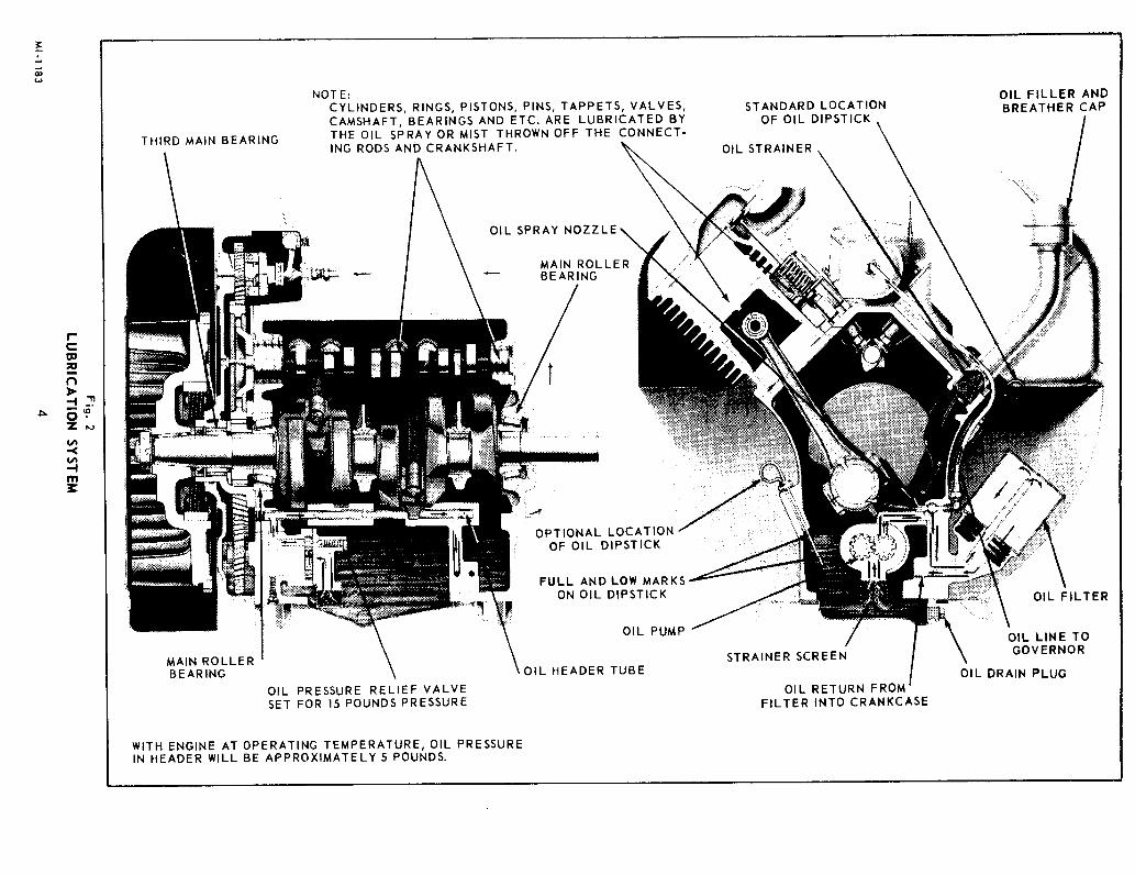
WIRING CIRCUIT, Fig. 26, Fig. 27
The fool-proof type connectors used prevent incorrectwiring from the stator to the rectifi r and regulatormodules. To disconnect plugs, squeeze outer ends ofr ceptical and pull apart.
The rectifier is insulated from ground, but the statorand regulator module are grounded to the engine thrutheir mounting surface. The regulator module thereforeshould not be removed and mounted at some remotelocation. This is a negative ground circuit. Connectground strap from negative post of battery to startingmotor flange, or good clean grounding surface onengine.
FLYWHEEL ALTERNATORSERVICE PROCEDURE:
PRELIMINARY TESTS
1. Visual Inspection should be made to eliminateconditions that may be interpreted as a defectedalternator. Examine leads for broken or loose con-nections, and make sure modules are securelymounted. The regulator module must be mountedto a metal surface for grounding purposes, (Test5.0) while the rectifier module, although insulatedfrom ground, should be securely mounted for heatdissipation. The mounting surfaces must be cleanand free of contaminaints, oil, grease, etc.
2. Check Battery. Use a Automotive battery in goodcondition, fully charged and with clean, tightterminal connections.
3. Check Ammeter. Be certain the ammeter is function-ing correctly. Amperage output is regulated byengine speed. The maximum amperage outputforModel W4-1770 is:
Maximum RPM I 10 AMP System I 25 AMP System
3000 9.5 amps 22 amps
When assur d that the problem is with the alternator,follow the tests outlined in ’Trouble Shooting’.
TROUBLE SHOOTING
FLYWHEEL ALTERNATOR12 VOLT - 10 AMP and 25 AMP Systems
Trouble Shooting Procedure is a guide showingmethods of testing the charging components. Thefollowing chart of Tests |.0 to 4.| are with the enginerunning, and substituting known good components inplace of suspected faulty components. Stotic Tests5.0 thru 7.2, following the running tests, are moreconclusive but some test require special WisconsinTest Lights.
Problem: Battery Overcharge Possible Cuase & Remedy
Test 1.0 Engine not runningcheck battery withDC Voltmeter.
1. I If voltage is great-er than 13.5 volts
1.2 With engine runningat full RPM, checkbattery voltagewith DC Voltmeter.
1.3 If the chargecreases beyond13.5 volts.
1.4 If the charge re-mains under 13.5volts.
1.1 Place 12 volt lightbulb or carbon pileacross battery to re-duce voltabe to below13.5 volts.
1.3 Faulty regulator. F~e-place, -- static checkregulator per TestNo. 5.1.
1.4 Alternator functioningproperly. Check bat-tery condition.
Fig. 27, WIRING DIAGRAM
ELECTRICAL SYSTEM
WITH
10 AMP or 25 AMP
FLYWHEEL ALTERNATOR
SOLENOID SWITCH
T BATTERY L
RECTIFIER REGULATORMODULE MODULE CHOKE \,
~ ~(optional)
il/ ----/ ~L STARTER PT-~
Make connections; for lights at charge SWITCHside of ammeter (negative terminal).
SPARK PLUGS
1
DISTRIBUTOR
HI -TEMP~ SWITCH
(optional)
IGNITIONCOIL
MI-1195 16

Problem: Low/No Charge Possible Cause & Remedy
Test 2.0
2.1
2.2
Proceed with Test1.0 and 1.1. It isnecessary toslightly dischargebattery t o makesystem work.
With engine runningat full RP~.~,, checkbattery voltagewith DC Voltmeter,
If the charge rate
2. 3 If system does notcharge
2.4
2.5
If charge rate in-creased with re-gulator disconnect-ed.
If the charge ratedoes not increasewith regulator dis-connected.
2.2 Alternator functioningproperly. [~attery wasfully charged.
2.3 Operate engine withregulator disconnect-ed (continue withTest2.4).
2.4 Regulator wasat fault.Replace regulatormodule, -- static checkregulator per TestNo. 5.1.
2. S Regulator not at fault.Check Rectifier perTest 3.0, 3.1 or staticcheck per Test 6.0.
Problem: Low/No Charge Possible Cause & Remedy
Test 3,0
3.1
3.2
3.3
Test conditionsand procedure thesame as 1.0 and1. I it is neces-sary to slightlydischarge bat-tery to makesystem work.
Plug new Rec-tifier in system.Run engine at fullRPM.
If the charge rateincreases witchnew rectifier insystem.
If the charge ratedoes not increasewith new Recti-fier --
3.2 Rectifier module was atfault. Pennanently in-stall new rectifiermodule.
3.3 Rectifier not at fault.Check Stator per Test4.0.
Problem: Low/No Charge Possible Cause & Remedy
Test 4.0
4.1
With engine stop-ped, unplug allconnectors be-tween modulesand stator. Startengine and run at2400 RPM. WithAC voltmetercheck voltage be-tween each of theblack stator leadsand ground.
If one of the twovoltages is zeroor they are over10% apart. --
4. 1 The stator is defectiveand should be r~placed.Static check stator perTests 7.0, 7.1, 7.2.
FLYWHEEL ALTERNATOR COMPONENTS
STATIC TESTSThe following test equip:sent is required:
DF83 Analyzer - Wisconsin Part, Fig. 28.DF 81 Flashlite Tester - Wisconsin Part, Fig. 28.VOLT-OHM-MILLIAMMETER Simpson 260 or equal.
The DF83 Analyzer was developed for testing thesolid state ignition and flywheel alternator compo-nents as furnished on Wisconsin engines. It is very
efficiently and economically powered by four transis-tor radio type 9 volt batteries. The DF81 FlashliteTester is used primarily for checking continuity.
DF83 ANALYZER
DF81 FLASHLITE TESTER
Fig. 28
REGULATOR TESTS
Test 5.0 REGULATOR GROUND
The YJ 60 Regulator module must be mounted to ametal surface for grounding purposes. Check for con-tinuity with a VOM (R x 1 scale) or test light.
TESTER TESTERRED LEAD BLACK LEAD RESULT
To Regulator To Ground " DF 83-Light OnBody DF 81 -Light On
VOM- Continuity
17 MI.II96

Test 5.1 REGULATOR STATIC CHECK
This test is an alternative or in addition to runningtests 2.3 and 2.4 (omitting r gulator). The DF 83Analyzer is used.
YJ 60 RE61JLATOR
NOTE: Module is defective if light indication is notshowrl.
ModuleBase Plate
ModuleRed Lead
Module3 Red Lead
ModuleRed Lead -
ModuleBase Plate -
ModuleBase Plate
ModuleBlack Lead
Then Remove
OFF
OFF
On AndRemain
On
BLACK LEAD
BLACK LEAD X ~
BLAC~O O O~ " WHITE LEAD
YJ 68 RECTIFIER (using DF 81 Flashlite)
TESTNO.
TESTER REDLEAD TO:
1 Mad uleWhite Lead
ModuleWhite Lead
TESTER BLACKLEAD TO:
OtherModule
Black Lead
EitherModule
Black LeadOther
ModuleBlack Lead
LIGHTINDICATION
ModuleWhite Lead
ON
ON
EitherModule Module OFF
Black Lead White Lead
OFF
RECTIFIER TESTS
Test 6.0 RECTIFIER STATIC CHECK
The diodes in the Rectifier module can be checkedwith any continuity device such as the DF 83 analyzer,DF 81 Flashlite or VOM. Since various testingdeviceswill differ in their operation, it should be noted in thefollowing three Rectilier test charts that the resultsin tests 1 and 2 should always be opposite to theresults of tests 3 and 4.
Y J68 RECTIFIER (using DF83 Analyzer)
Module is defective if light indication is not as shown.
ModuleI White I_ead
Module2 White Lead
Either3 Module
Black Lead
Other4 Module
Black Lead
EitherModule
Black Lead
at’herModule
Black Lead
ModuleWhite Lead
ModuleWhite Lead
OFF
OFF
ON
ON
YJ 68 RECTIFIER (using VOM equipment)
Note: Continuity shall be in one direction only. Ifreadings are not as indicated, replace module.
TESTNO.
I
2
3
4
VOM RED VOM BLACK METERLEAD TO: LEAD TO: INDICATION
ModuleWhite Lead
ModuleWhite Lead
EitherMad u le
Black Lead
EitherModule
Black LeadOther
ModuleBlack Lead
No Continuity ’
No Continuity
ModuleWhite Lead
OtherModule Module Continuity
Black Lead White Lead
Continuity
STATOR TESTS
YB81,10 amp STATOR YB82,25 amp STATOR
The continuity tests for stators is ~not a 100% method of checking. How-ever, if the stator fails the continuitytests, it is definitely defective. If itpasses the tests but all other compo-nents have also checked out O.K., the stator may bethe defective part of the system and should be re-placed, Test can be made with Stator on engine.
M1-1197 18

Test 7.0 STATOR GROUND
Like the R gulator, th YB81 and YB82 Stators mustbe grounded. Stator ground can he checked with anytype continuity device.
TESTNO.
To Stator1 Black Lead
TESTER TESTER RESULTRED LEAD BLACK LEAD
To Ground
To Other2 Black Lead To Ground
OF 83- Light OnDF 81 - Light OnVOM- Continuity
Test 7.1 STATOR CONTINUITY
This test should be performed after 7.0 stator groundtest. Use continuity equipment such as DF81 Flash-lite or VOM. Results other than specified indicate adefective stator.
TEST.,NO-
1
2
3
TESTER TESTER RESULTRED LEAD BLACK LEAD
To Ground To StatorRed Lead
To StatorTo Ground Black Lead
To Ground To OtherBlack Lead
DF 81 - Light OnVOM- Continuity
Test 7.2 CONTINUITY with DF 83 Analyzer
I Stator _ .1 I Black Lead ~rouna -
Stator OtherBlack Lead
Ground
Ground
StatorRed Lead
StatorBlack Lead
Stator Other3lack Lead
On
On
On
On
On
TERMINAL ’
r]W. BLK. BLK| I Jri W. REDII.a----TERMINALo o ,o I % o o II PLUGIf light indication is other than shown, stator is de-fective. If stator checks out good, perform voltagetest 7.3.
Test 7.3 STATOR RUNNING VOLTAGE
With the engine stopped, unplug all connectors be-tween modules and stator. Start the engine and run atoperating speed. Perform the following tests with anAC voltmeter:
TEST METERNO. RED LEAD
METERBLACK LEAD
To OtherStator
Black Lead
To StotorBlock Lead To Ground
To Ground
STATORDEFECTIVE IF:Either Reading
is O
Readings Varymore than 10%
BELT DRIVEN ALTERNATOR
Tic 12 volt- 37Amp Automotive q/pc Almmam¢ is optionally availablein placeofthc Flywheel Alternator. No maintenance or adjustments arercquircd other than periodically checking for loose, broken or dirtywire-terminal connections, and for proper drive belt Lcnsion. Beatingsarc pre-lubricated, no additional lubrication is necessary. The Regula-tor is an all electronic transistorized devise, therefore no mechanicalcontacts or relay adjustments are necessary for voltage regulation.
The alternator is wired into the engine electrical system per Fig. 29.
IMPORTANT
This is a Negative Ground system. Charging components will bedamaged if grounded wrong in connecting or jumping batteries.
A Caution: Handle battery carefully to prevent acid bums. Avoidsparks near battery - gas given off by battery is explosive.
PRECAUTIONS to be exercised in the use of belt driven alternator:.l. Observe proper polarity when installing battery; negative battery
terminal must be grounded. Reverse polarity will destroy the rectifierdiodes in alternator.
2. As a precautionary measure, disconnect ground battery terminal whencharging battery in vehicle. Connecting charger in reverse will destroythe rectifier diodes in the alternator.
3. Do blot, under any circumstances, short the field terminal of thealternator to ground, as permanent damage to the regulator may occur.
4. Do blot, remove the alternator from the vehicle without first discon-necting the grounded battery cable.
5. Do blot, operate engine with battery disconnected, or disconnect thealternator output le~d while the alternator is operating, as dampingeffect of the battery will be lost. The voltage will rise to an extreme valueand permanent damage to the regulatcx may oc.x:ur.
6. Do blo~ disconnect the voltage regulator while the alternator isoperating, because the large voltage transient that occurs when discon-nection takes place may damage the regulator.
7. Cautiofl: Output wires from Alternator to Ammeter, and from Amme-ter to battery terminal on starting solenoid must be of sufficient size forcharging 37 amps. Use No. 10 gage stranded wke, or larger.
30 AMP FLYWHEEL ALTERNATOR
An improved 30 amp flywheel alternator system is now available as anoption on W4- i 770 engines. This improved 30 amp system iscapableofhigheroutput at lower engine speeds over the 25 amp flywheel alternator system.
This new 30 amp system can be easily recognized by the single regulator-rectifier module. The combination regulator-rectifier (Y J70) is mountedto the cylinder shroud on the W4-1770. The YJ70 must be securelymounted to a location that will allow cooling of the unit.
19

Fig. 29, WIRING DIAGRAM
ELECTR|CAL SYSTEM
WITH
BELT DRIVEN At.TERNATOR
AND
SOLENOID STARTING
12 VOLT
Make connections; for lights at chargeside of ammeter (neg. term.). For Equip-ment Solenoids, at Solenoid Switch-Bottery side.
SOLENOID
l~ I SPARK
~ SWITCH STARTING 4 2C= PLUGSMOTOR 1 ~
~-~ ~11,~
3
~~~Rotation
~ ~AUTOMATICI~ STARTER~ CHOKE
SWITCH (Optional)
DI~IBUTORIGNITIONSWITCH
~@
HI- TEMPERATURESAFETY SWITCH
IGNITION (Optional)
COl L
BELT DRIVEN~ REGULATORALTERNATOR
In addition to a new style regulator-rectifier, a new stator (YB84) used for this 30 amp system. Also, the magnet ring in the flywheel isdifferent than the 25 amp system. In order to change a W,I-1770 fromthe 25 amp system to this improved 30 amp system, the regulator-rectifier, stator, flywheel, wiring and cylinder shroud must be changed.
30 AMP FLYWHEEL ALTERNATOR TESTING
When testing a charging system which uses the Y J-70 rectifier-regulator module, the following items should be checked:1. That the charging system is properly wired.2. That all connections are clean and tight.3. That the battery is in good condition.
The testing should begin by testing the A.C. voltage output of the statorwhere the 2 leads attach to the Y J-70. Disconnect the stator]eads from theY J-70 and hook them up to a volt-ohm meter. Use the A.C. voltage scaleand the reading should be between 20 and 50 volts A.C. depending uponthe engine rpm. (The faster the engine speed, the higher the A.C. voltageshould be.) This test checks the stator and magnet ring. If the chargingsystem passes all the previously mentioned checks, then the YJ-70module c an be checked as shown below. Use a good quality ohm meter.All readings are done on the RX100 scale. Do not attempt to use theDF83 analyzer or any other type continuity tester.
3. Pos.(+)------’~
NOTE
If when performing the above test the YJ-70 tests bad, try reversingthe Ohm meter leads and redo the test. Some brands of Ohm metersare reversed polarity from the Ohm meter used to develop this testand will give you incorrect readings unless you reverse the test leads.
WIRING DIAGRAM, 30 amp Flywheel Altenator with Positive EngagementSarter and Solid State Ignition, Models VH4D, VG4D and W¢1770."
HIGH TEMPERATURE SAFETY SWITCH, Fig. 30
As a safety precaution against overheating, engines are optionallyequipped with a high temperature switch mounted to the cylinder headat No. 4 spark plug.
When cylinder head temperature becomes critically high, the safetyswitch will automatically stop the engine by shorting out the ignitionsystem. A waiting period of about 10 minutes will be required beforethe switch has cooled off sufficiently to restart the engine. An over-heated engine will score the cylinder wails, bum out connecting rodand crankshaft bearings, also damage pistons and valves. The causeof the overheating condition will have to remedied before the engineis resarted. See Engine Overheads paragraph in Troubles, Causesand Remedies section.
20

.,./ CONNECT TO DISTRIBUTOR OR/. MAGNI~TO GROUND TER/dlNAL/
\ ’, /" SWITCH OPPOSITE¯ ’" ’.’ ’)~: // NO. 4 SPARK PLUG
HIGH TEMPERATURE ~SAFETY SWITCH
Fig. 30
ENGINE TROUBLES: CAUSES AND REMEDIES
The three prime ~equisitos essential to starting and maintaining satis-factory operation of internal combustion engines are:
1. A proper fuel mixture in the cylinder.2. Good compressiou in the cylinder.3. Good spark, properly timed, to ignite the mixfure.
If all three of these conditions do not exist, the engine cam’tot be started.There are other factors which will contribute to hard starting; such as,too heavy a load of the engine to turn over at a low starting speed, along exhaust pipe with high back pressure, etc. These conditions mayaffect the starting but do not indicate that the engine is improperlyadjusted.
As a guide to locating starting difficulties which might arise, the fol-lowing causes are listed under/he three headings: Fuel Mix ture, Com-pression, and Ignition.
In each case, the causes of trouble are given in the order in which theyare most apt to occur. If the remedy is apparent, no further remediesare suggested.
STARTING DIFFICULTIES
FUEL MIXTURE
¯No fuel in tank or fuel shut-off valve closed.¯Plugged vent hole in fuel tank cap.¯Faulty Fuel pump. Diaphragm in pump worn or punctured.¯Carburetor not choked sufficiently, especially if engine is cold.¯Water, dirt, or gum in gasoline interfering with free flow of fuel to
carburetor. Clogged fuel filter screen.¯Poor grade or stale gasoline that will not vaporize sufficiently toform the proper fuel mixture.
¯Dirt or gum holding float needle valve in carburetor open. Thiscondition would be in indicated if fuel continues to drip fromcarburetor with engine standing idle. Often tapping the floatchamber of the carburetor very lightly with the handle of a screwdriver or similar tool will remedy this trouble.
¯Restricted or dirty air cleaner.¯Faulty carburetor - requires overhaul.¯To test for clogged fuel line, loosen fuel line nut at carburetor slightly.
If line is open, fuel should drip out at loosened nut.
COMPRESSION
Caution: Disconnect spark plug wires to prevent engine fromaccidendy starting.
If the engine has proper compression, considerable resistance will beencountered on the compression stroke when turning engine crank-shaft over slowly by hand. If resistance is not encountered compres-sion is faulty.
Restore Compression. To an engine that has been out ofoperation for a period of time, in which the oil has drained off thecylinders, by removing the spark plugs and pour about a fluid ounceof crankcase oil through the spark plug hole in each cylinder. Turnengine crankshaft over several times to distribute the oil over thecylinder walls, then reassemble spark plugs and compression shouldbe satisfactory.
Compression. Check using acommercial compression test gauge;Wis-Con Total Power does not consider it practical to publish a p.s.i.compression figure because of the variables involved, engine,condition, method of testing, and rpm of test. Our recommendation isthat whatever gauge test is performed, a variation of more than 10p.s.i, between cylinder would indicate leaking rings, valves or any ofthe following:
Valve stuck open due to carbon and gum on valve stem, orleaking valve seat, see q/alves’, page 31.
Valve tappets adjusted with insufficient clearnace under valvestems. See "Valve Tappets, page 12.
Piston rings worn, broken, or stuck in pistion due to carbonaccumulation. See ’Piston and Connecting Rod’, page 29.
Loose spark plugs or broken spark plug. In this case a hissing noisewill be heard when cranking engine, due to escaping gas mixture oncompression stroke.
Damaged cylinder head gasket or loose cylinder head. This will like-wise cause hissing noise on compression stroke.
IGNITION
Check Distributor or Magneto "Ignition Spark’ per instructions andFig. 31 on page 22. No spark or weak spark may be attributed to thefollowing:
¯ [gn.[tiou cable loose or disconnected at coil, distrbutor or magneto,or spark plugs.
¯Broken or frayed ignition wires.¯Spark plugs wet or dirty.¯Spark plug gap incorrect, (see page 9).¯Condensation on spark plug electrodes.
21

¯Breaker point gap incorrect, (see page 10).¯Breaker points pined or fused.¯Breaker arm sticking.¯Condenser leaking or gronnded.¯Spaxk timing wrong, (see page 12).¯Weak battery. Faulty ignition coil.
ENGINE MISSES
¯Spark plug gap incorrect, (see page 9).¯Worn, leaking or loose ignition cables.¯Weak spark or no spark in one of the cylinders, (see ’Ignition’, test
for spark, page 22).¯Loose connections at ignidon cables.¯Breaker points pitted or worn.¯Water in gasoline.¯Poor compression, (see ’Compression’, page 21).
ENGINE STOPS
¯Fuel tank empty.¯Water, dirt or gum in gasoline.¯Gasoline vaporized in fuel lines due to excessive heat around engine(Vapor Lock), (see ’Stopping Engine’, page
¯Vapor lock in fuel lines or carburetor due to using wintter gas (toovolatile) in hot weather.
¯Air vent hole in fuel tank cap plugged.¯Engine scored or stuck due to lack of oil.¯Ignidon troubles, (see ’Ignition’, see page 21).
ENGINE KNOCKS
¯Poor grade of gasoline or of low octane rating.¯Engine operating under heavy load at low speed.¯Carbon or lead deposits in cylinder head.¯Spark advanced too far, (see "liming’, page 12).¯Loose or burnt out connecting rod bearing.¯Engine overheated due to causes under previous headings.¯Worn or loose piston pin.
ENGINE BACKFIRES THROUGH CARBURETOR
¯Water or dirt in gasoline.¯Engine Cold.¯Poor grade of gasoline.¯Sticky inlet valves.¯Overheated valves.¯Spark plug heat range incorrect (too hot).¯Hot carbon particles in engine.
ENGINE OVERHEATS
¯ Crankcase oil supply low. Replenish immediately.¯ Ignidon spark timed wrong, (see "liming’, page 12)¯ Low grade of gasoline.¯ Engine overloaded.¯ Restricted cooling air circulation.¯ Part of air shroud removed from engine.¯ Dirt between cooling fins on cylinder or head.¯ Intake screen clogged with dirt.¯Engine operated in corff’med space where cooling air is continually
recirculated.¯Carbon in engine.¯Dirty or incorrect grade of crankcase oil.¯Restxicted exhaust.Engine operated while detonating due to low octane gasoline or heavyload at low speed.
ENGINE SURGES OR GALLOPS
¯Carburetor flooding¯Governor spring hooked into wrong hole in lever (see ’Governor
Adjustment’, page 11).¯Governor spring tension incorrectly adjusted.¯Governor or throttle linkage binding, worn or disconnected.
MAGNETO DISTRIBUTOR
Fig. 31, IGNITION SPARK
If difficulty is experienced in starting the engine or if engine missesfiring, the strength of the ignition spark may be tested as follows:Distributor Ignition, disconnect the cables form all towers on thedistributor cap, except the center coil tower. Insert a stiff piece ofwire or metal rod into one of the sockets. Hold the terminal of thistower 1/8 inch from the wire or rod. Magneto Ignition, disconnectNo. 1 ignition cable from spark plug, wedge a piece of bare wire upinto the terminal boot and let an end of the wire extend out. Holdterminal so that wire is about 1/8 inch from metal turn enginecrankshaft over two complete revolutions and watch for a spark todischarge during the cranking cycle.
Repeat this check with each of the other ignition cables. A good sparkfrom each of the towers will eliminate the ignition coil and distributor(or magneto) as the source of trouble. If there is a weak spark, or spark at all, check breaker point gap, condenser and ignition coil.
22
ENGINE DISASSEMBLY and REASSEMBLY
OVERHAUL
An engine overhaul shall be deemed necessary if atleast one of the following occur:
I. A I0% loss in horsepower.
2. Oil consumption of one quart or more every 12hours of operation.
3. A major engine part failure.
Under normal operating conditions and with scheduledmaintenance, a suggested period between overhaul;
2000 Hours: For Intermittent load applications using65 to 85% of horsepower at 1500 to 3000 r.p.m.
1500 Hours: For continuous load applications using85 to 95% of horsepower at 2400 to 3000 r.p.rn.
SAFETY NOTICE
Correct repair and adjustment are very important forsafe and reliable engine operation. It is impossibleto evaluate and advise of all the conceivable ways inwhich service work should be done, or of the unsafeconsequences of each way. Use common sense andsatisfy yourself that what you are doing will notjeopardize your safety, the safety of others, or causedamage to tt~e engine.
A Caution:
1. Engine repairs should be made only by an experi-enced mechanic.
2. Wear safety glasses and safety shoes.
3. Do not clean parts with gasoline - use a commer-cial petroleum solvent, or ’de-greaser’, accordingto instructions.
4. When using air pressure for cleaning, wear safetyglasses and protective clothing.
5. Keep work area clean of spilled fuel and oil.
6. Store oily rags in a fireproof container.
7. Do not smoke in work area or where batteriesare stored.
8. Comply with recommended torque valves whentightening screws and nuts.
9. Replacement screws must be of equal or bettergrade of steel.
PREPARATION and SUGGESTIONS
Clean the engine ’before attempting to repair it. Re-move as much dirt and grime as possible before re-moving any parts. This will make the repair job muchcleaner and reduce the possibility of getting harmfuldirt particals inside the engine.
Provide a well lighted working area with enough spacefor parts and tools to be spread out. A work stand isessential for holding the engine securely while remov-ing or tightening parts.
When disassembling the engine, lay the parts out inthe order that they were removed. Have several box savailable so that parts belonging to certain groupscan be kept together. Tag parts if there is a possibi-lity of confusion.
It is suggested that reference also be made to enginePARTS MANUAL for reassernbly. The exploded illus-trations will help in identifying parts, show the com-ponents of individual assembly groups and presents avisual order of reassembly.
Drain Oil From CrankcaseBefore Disassembly"
All parts should be thoroughly cleaned and inspectedfor possible replacement. Use new gaskets in reas-
sembly and lubricate all bearing surfaces.
TOOL REQUIREMENTS
Other than the conventional socket wrenches, screwdrivers, pliers, hammer, etc., the following tools mayalso be required.
Box wrench, 1- 11/16" offsetTorque wrench (0-50 ft. Ibs.)Puller, idler shaft ( Wisconsin DF67)Expander, piston ringCompressor, piston ringValve LifterPuller, insert (Wisconsin DF66 A)Driver, insert (Wisconsin DF 69)Driver, valve guide (Wisconsin DF72)Dial IndicatorsMicrometers
DISASSEMBLY and REASSEMBLYPROCEDURES
With the disassembly operations, instructions on re-assembly are also given, as often it will not be neces-sary to disassemble the entire engine. If it is desiredto disassemble the entire engine, the reassernbly in-structions can be looked up under the headings of thevarious parts.
ACCESSORIES
Remove clutch or clutch reduction unit if engine isequipped with either of these accessories.
AIR CLEANER can be removed as a complete unitwhen flywheel shroud is removed. Disconnect tubingand elbow connection from carburetor to air cleaner.
CONTROL PANEL can remain on flywheel shroud,but disconnect: ignition wires, choke wire at carbu-retor and variable speed control if furnished.

OIL FILTER is remov d by tapping side of cartridgewith a mallet to break the seal. Then pierce can withscrew driver or similar pointed tool to serve as ahandle for unscrewing filter cartridge. Place a panunder the filter to catch oil leakage as filter is re-moved. Disassemble filter bracket from side of crank-case by taking off two mounting screws.
STARTING IdOTOR is removed by disconnecting ig-nition wires at solenoid and taking out the three cap-screws holding starter to flange on flywheel shroud.
SCREEN on front face of flywheel shroud must be re-moved in order to take off the flywheel.
FLYWHEEL, Fig. 32, 33
After the flywheel screen has been removed, straightenout the bent tabs on flywheel nut lockwasher. Then,by means of a 1- 11/16 inch offset box wrench, loosenflywheel nut by striking the handle of wrench a sharpblow with a soft hammer. Do not use an open end,monkey or pipe. Do not remove flywheel nut, but un-screw it flush with the end of tile crankshaft.
A Caution: Wear safety glasses when using ahammer to straighten lockwAsher tabs, loosen-ing flywheel nut and flywheel.
The flywheel is mounted to a taper on the crankshaft.Take a firm hold on the flywheel fins, pull outwardand at the same time strike the end of the flywheelnut several times with a babbitt hammer. See Fig. 32.The flywheel will slide off the taper of the crankshaftand can be taken off after the flywheel nut is removed.Striking the end of the flywheel nut instead of directlyon the crankshaft will prevent serious damage to thethreads at the endof the shaft. Also do not use ahardhammer as it may ruin the crankshaft and bearings.
TABIN KEYWAY xN
BEND~TAB OVER
FLAT OF NUT
FLYWHEEL NUT-~’-~
FLYWHEEL~
Fig. 33
Important: Carefully remove and reassemble flywheelso as not to damage flywheel alternator rotor andstator.
In Reassembly; be sure the g:oodruff key is in positionon the shaft and that the keyway in the flywheel islined up accurately with the key. After mounting; seatflywheel on crankshaft taper by slipping a piece ofpipe over the end of the crankshaft and against thehub of the flywheel, and striking the end of the pipea sharp blow with a hammer.
Assemble new lockwasher with bent tab placed intoflywheel keyway as illustrated in Fig. 33. Securelytighten flywheel nut, then bend at least one tab oflockwasher over flat of flywheel nut, to prevent nutfrom loosening.
.~IR SHROUDING, Fig. 34
First disconnect ignition wires at spark plugs, thenremove cylinder head covers, and the screws mountingflywheel shroud to lower cylinder shrouds and cylinderheat deflectors. Flywheel shroud with side coverattached can be removed after takingout the six screwsmounted to the gear cover. Balance of shrouding canbe removed when it is convenient to do so.
HEATDEFLECTORS
SIDECOVER
FLYWHEEL NUT(flush with end
of shaft)
LOCKWASHER
Fig. 32
CYLINDER ALTERNATOR STATOR FLYWHEELSHROUD SHROUD
F~g. 34
M I -I 203 24
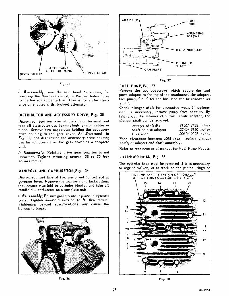
DISTRIBUTOR
ACCESSORYDRIVE HOUSING
~ DRIVE GEAR
Fig. 35
.In Reassembly; use the thin head capscrews, formounting the flywheel shroud, in the two holes closeto the horizontal centerline. This is for stotor clear-ance on engines with flywheel alternator.
DISTRIBUTOR AND ACCESSORY DRIVE, Fig. 35
Disconnect ignition wire at distributor terminal andtake off distributor cap, leavinghigh tension cables inplace. Remove two capscrews holding the accessorydrive housing to the gear cover. As illustrated inFig. 35, the distributor and accessory drive housingcan be withdrawn from the gear cover as a completeunit.
In Reassembly; Relative drive gear position is notimportant. Tighten mounting screws, 25 to 30 footpounds torque.
MANIFOLD AND CARBURETOR, Fig. 36
Disconnect fuel line at fuel pump and control rod atgovernor lever. Remove the four nuts and lockwashersthat secure manifold to cylinder blocks, and take offmanifold - carburetor as a complete unit.
In Reassembly; Be sure gaskets are in place in cylinderports. Tighten manifold nuts to 18 ft. |bs. torque.Tightening beyond specifications may cause theflanges to break.
Fig. 36
ADAPTER ~ FUEL
~. MOUNTING~- ~’~-~ ~ SCREWS
~.~ ~ ~~ i ~ PLUNGER~ ~ SHAFT
~ CAMSHAFT
Fig. 37
FUEL PUMP, Fig. 37Remove the two capscrews which secure the fuelpump adaptor to the top of the crankcase. The adapter,fuel pump, fuel filter and fuel line can be removed asa unit.Check plunger shaft for excessive wear. If replace-ment is necessary, remove pump from adapter. Bytaking out the retainer clip from inside adapter, theplunger shaft can be removed.
Plunger shaft dia. .3720/.3715 inchesShaft hole in adapter .3740/.3730 inchesClearance .0010/.0025 inches
~/hen clearance becomes .005 inch, replace plungershaft, or adapter and shaft assembly.
Refer to rear section of manual for Fuel Pump Repair.
CYLINDER HEAD, Fig. 38
The-cylinder head must be removed if it is necessaryto regrind valves, or to work on the piston, rings or
HI-TEMP SAFETY SWITCH OPTIONALLYMTD AT THIS LOCATION - No. 4 CYL.
15 14 13 21
316
417
2O
518
19
12
11
122
10
6 7 8
Fig. 38
25 M~.12o4

~~GOVERNOR
GEAR COVER \ SPRINGSPACER ~
Oil Groove in Shaft ~aligned with notch \in gear cover/~ ~ ~ ge inside flyweights
and against thrust pi~sa n d
GOVERNOR ~SHAFT
~OIL LINE
THRUST SLEEVE andFLYWEIGHT ASSEMBLY
THRUST WASHER/Mount pins with slot toward gear
Mount Oil Sealwith Lips in.
HOUSING
F
connecting rods. All of the cylinder head screws areplainly in view and can be easily removed. Screws ofdifferent lengths are used but these can be properlyreassembled according to the various lengths ofcylinder head bosses.
Hi-temp $ofety Switch, optionally furnished, is mount-ed to the cylinder head opposite the No. 4 spark plug,see Fig. 30. Switch must be remounted in this samelocation or it will not function properly.
In Reossembly; Remove all carbon and lead depositsfrom combustion chamber. It is recommended that newcylinder head gaskets be used as the old gaskets willbe compressed and hard and may not seal properly.Use a mixture of graphite and oil on the cylinder headscrews to prevent them from rusting tight against thecylinder block. Tighten cylinder head screws to 24 ft.Ibs. torque in the sequence shown on Fig. 38. Aftercomplete assembly and engine is run in, re-torquehead screws.
GOVERNOR, Fig. 39
Unhook governor spring and disconnect oil line atgovernor housing. Take off the four screws and lock-washers that secure the governor housing to the gearcover spacer and remove housing. Slip flyweight assem-bly, along with thrust washer, off of stationary gover-nor shaft in gear cover.
GOVERNOR -CLEARANCE and WEAR LIMITS (inches)
DESCRIPTION
Cross ShaftDi ameter
Cross Shaft Holedia. in Housing
Gear Shaft Diameter
ORIGINALDIMENSION CLEARANCE
.309 /.310
¯ 312 /.313 .002 -.004
.4270/.4275
Gear Hole Diameter .429 /.430 .0015- .003for Shaft
I.D. of Thrust Sleeve .429 /.431 .0015-.004
WEARLIMIT
.002
.002
.002
.002
.003
Fig. 40
ig. 39
In Reassembly; Clean and lubricate all bearing sur-faces. Replace parts that are damaged or if there isexcessive wear, see Chart Fig. 40. Place thrust wash-er, gear-flyweight and thrust sleeve on to governorshaft. NOTE: flange of thrust sleeve must be insidethe flyweights and against the flyweight thrust pins.
FLYWHEEL ALTERNATOR, Fig. 41
Stator can beleft on gear cover and removed as a com-plete unit as illustrated in Fig. 42. Or stator can beremoved if necessary by first taking out the four#10-32 screws by means of a 5/32 inch Allen wrench.Then, place a hook type pry bar alternately in thearea behind the two stator dowel pins, and pry statormounting surface loose. Be careful not to damage coilwindings.
In Reassembly; With wire harness toward gear coverand in line with directional notch, place stator mount-ing surface over dowel pins and gently tap in place.Apply # 242 Loctite to the Four # 10-32 screw threadsand securely tighten stator to gear cover.
PRY BAR
Wire harness in directionalnotch of gear cover.
Fig. 41
26

THRUST PLUNGER=nd SPRING
GEARCOVER
!
SPACERPLATE
GASKET
HANGER
~STATOR¯ ASSEMBLY
DOWELPINS
Fig. 42 ..
GEAR COVER, Fig. 42Remove ten capscrews and lockwashers from the outergear cover flange and two from the spacer plate sidenear the governor. With a drift punch, drive the twodowel pins from the gear cover flange thru the crank-case face, then remove gear cover.
Take thrust plunger and spring, Fig. tl, out from end:of camshaft to prevent them from falling out and
being lost. ~
In Reassembly; Insert thrust plunger and spring intoend of camshaft. Mount gasket to spacer plate face,using a thin coat of oil or grease to hold it in place.Assemble gear cover to spacer plate by means of thetwo dowel pins, be very careful not to damage ’0’ ringsea/ on bearing hanger. Then, mount the twelve cap-screws and lockwashers, and tighten 14 to 18 ft. Ibs.torque.
IDLER GEAR
3/8"-16BOLT
SHAFT PULLER
ALLEN HEAD SET SCREWLOCATED IN CRANKCASE
Fig. 43
IDLER GEAR AND SHAFT, Fig. 43
The idler shaft is locked in place by a set screw onthe side of the crankcase below the oil header. Re-move set screw with a 5/32 inch Allen wrench, andtake off idler shaft by means of Wisconsin DF-67puller and the 3/8~- 16 tapped puller hole in end ofshaft. Slip idler gear out from behind bearing hanger.
In Reassembly; Inspect for wear-maximum allowableclearance between idler shaft diameter and I.D. ofgear is .0045 inches. Be sure oil groove in shaft isfacing up. Then, with idler gear in place, drive shaftinto crankcase with a soft metal hammer and maintaina .003 to .004 inch clearance between idler gear andshoulder of shaft. Lock shaft in place with the Allenset screw.
Fig. 44
CAMSHAFT GEAR, Fig. 44, 45
If" either camshaft gear or outboard bearing housinghave to be removed, they must be removed together.First, take out the three gear capscrews and lock-washers, then proceed to remove gear as far as it willcome off by means of a large screw driver or similarwedge tool. Completely remove gear after outboardbearing housing is loosened.
In Reassembly; The off set mounting holes provide anaccurate assembly for valve timing - the gear canonly be put on the correct way. Position camshaft sothat when gear is mounted the timing mark matches uPwith marked gear tooth on crankshaft gear, .~ue Fig. 11.
Be sure that thrust plunger and spring are in place atend of camshaft before gear cover is mounted.
OUTBOARD, 3rdMAIN BEARING, Fig. 45,46
Take out the three housing mounting screws using a12 point, 3/8 inch socket. Slide housing off crankshaftenough so that camshaft geor can be taken off. Then,completely remove housing assembly.
In Reassembly; Check needle bearing and inner oilseal for possible replacement. Inner needle bearingrace is mounted to the crankshaft using #601 Loctite.Oil seal is mounted with lips facing, inward, seeFig. t6. If main roller bearing is replaced, mountbearing cup extended out .125 (+ .000-.002) inchesfrom face of crankcase as shown.
27 M~ -1206

CAMSHAFTGEAR
OUTBOARDBEARINGHOUSING
CRANKSHAFT GEAR
IR SHAFT HOLE
OIL PUMP GEAR
Fig. 45
.~1L._.__ .125
BEARING- FLUSH \ "~,/~WITH HOUSING FACE F~’ ~
NEEDLE BEARING
OIL SEAL(lips inward
LOCTITE
NEEDLE BEARINGRACE
’0’ RINGOIL SEAL
Fig. 46,
Tighten housing mounting screws 40 to 45 ~t. Ibs.tarque and use a new ’O’ring oil seal around outerdiameter of housing.
GEAR TRAIN, Fig. 47
~ith the gear cover removed and without illustratingthe outboard bearing, the complete gear train is shown.
Future reference can be made to Fig. ¢7 when assem-bling crankshaft and camshaft, as accurate locationof the timing marks is essential for proper engineoperation.
ENGINE SUPPORTS AND OIL PAN, Fig. 48
Invert engine to a position where the bottom of theengine will be accessible. If possible, use a workbench with a clearance hole in it of about 4 inches in
CAMSHAFT THRUSTPLUNGER AND SPRING
GOVERNOR GEAR
CAMSHAFT GEAR
TIMING MARCRANKSHAFT
GEAR
ACCESSORYDRIVE GEAR
IDLER GEA~/
OIL PUMPGEARLOCKNUT
’OIL PUMP GEAR
Fig. 47, GEAR TRAIN WITHOUT OUTBOARD BEARING
diameter. Extend the crankshaft thru the hole and restthe engine on the main bearing plate flange. Removethe engine support mounting screws with a 3/4 inchsocket wrench, and the oil pan screws with a 1/2 inchwrench.
In Reossembly; Use a new oil pan gasket, and mountoil pan with oil drain to either side - oil filter sideis standard. Use Perma-tex on screw threads andtighten 6 to 9 ft. Ibs. torque.
Mount engine supports and tighten capscrews to40 h. Ibs. torque.
OIL PUMP, Fig’s. 49, 50
Remove locknut and oil pump drive gear from shaft,see Fig. 50. If gear is too tight to remove by hand,use a puller. Hammering on end of shaft to loosen gearwill damage pump.
Fig. 48
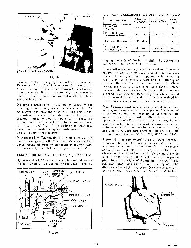
PIPE PLUG.
ALLEN HEAD LOCKSCREW
OIL PUMP
Fig. 49
Take out slotted pipe plug from bottom of crankcase.]:3y means of a 5 32 inch Allen wrench, remove lock-screw from pipe plu~ hole.. ~);ithdraw oil pump from in-side crankcase. If pump fits too tight to remo;e by
hand, tap front of pump housing (not shaft), with ham-met and brass rod.
Oil pump disassembly; is required for inspection andcleaning if faulty pump operation is suspected. Re-
move cover assembly and wash in a coro_.mercial clean-ins solvent. Inspect relief ,.alve and check cover forcracks. Thoroughly clean oil passa,g(.q in body, andinspect ~ears, shafts and body for excessive, wea~,
s,’,’ /";.....3~ .nd /";,~..’;i. In addition to individualparts, body assembly cunplete with gears ~s avail-able as a service replacement.
In Reagsembly; Thoroughly, oil internal ge,,rs, anduse a new gasket (..003" thick), when ass, emblingcover. Mount oil pump to crankcase in reverse orderof disassembly, and lock body in place per t"i::, l~C
CONNECTING RODS and PISTONS, Fig. 52,53,54,55
By means of a 1/2" socket wrench, loosen and removethe hex locknuts from connecting rod bolts. Then, bv
DRIVE GEAR PUMP INTERNALBODY D R I VRE N /
I INTERNALDRIVELOCKNUTGEAR
GASKET
COVER ASSEMBLY
RELIEF VALVE
LOCKSCREW
STUB SHAFT
Fig. 50
OIL PUMP -CLEARANCE and WEAR LIMITS (inches)
ORIGINALDIMENSION
DESCRIPTION CLEARANCE
Drive ShaftDiameter .5000 ".4995
Drive Shaft HoleDiameter in Body .5015 ,5005 .0005-.002
Stub Shaft Diameter .-1975 .4970
Gear Hole Diameter.49~ [ .0005-.002For Stub Shaft
WEARLI I~IT
.002
.002
.002
.002
Fig..5]
tapping the ends of the bolts; lig, htlv, the connectingrod cap will break free from the bolts.
Scrape off all carbon deposits that might interfere withremoval of pistons from upper end of cylinder. Turnc’ranksh,fl unHl piston is ~t top, then push connectingrod ~,nd p~ton assel:lblv upward ,nd out thru topcylinder. Be careful not to mar the crank pin by allow-
ins the rod bolts lu strike or scrape across it. Placecaps on rods immediately so that they will nnt he m~-matched in feasgemblv. Note: Tag connecHng rod andpiston assemblies go that thevcan be reassembled in-~o the same cvlindur ihat tht,k were removed from.
~hell Bearings must St? currect[v mounted ~o the, cnn-netting rod in reossemgJy. The c~p ~hould beto the rod so that the Io¢etin~ lu~ uf l)~th ht.;~rinRhalves are on the same side ~ ~ilustr~dud in /,~. ,_’.Spread a film of uil on back ~f shell bc~rtn~, he,fort-mounting to hel F hold them in place, duringRefer to chart, It,z. ~l for clearance betweenand crank pin. Undersiz~ shell be;~rm~ are art, liablefor service in si,~e~, ~f .~)1", .002", .010" and .020".
Piston skirt is c~m-9roond to an e]liptLcal contour.Clearance between the p~ston and cylinder must bemeasured at the center of the thrust face at the bottomof the piston skirt. ~efer to Chart, Fig. ~1 for properclearance. The thrust [ace on the piston a~e the widesection of the piston, 90° from the axis of the pistonpin hole, on both sides of the piston, ~’~ ]"i;:. ~7. Themax/mum thrust ~a¢~ is the wide side opposite thedirection of c~ankshaft rotation. Diameter at piston atbottom of skirt thrust faces is3.2455 3.2465 inches.
LOCATING LUGS
STAMPED
~~ NUMBERS
SHELLBEARING
Fig. 52
29 ~-~ 208

OIL HOLE
OIL SPRAY NOZZLES
Fig. 53
In Reassembly; Be sure piston and connecting rodassemblies are put back into the same bore from whichthey were removed. Lubricate the crank pins, pistonassembly and cylinder walls with No. 30 S.A.E. oil,and stagger the ring gaps 90° around the piston. Usea standard automotive type ring compressor, and in-
sert rod end into cylinder from cylinder head end.Note: Rod bearing should be parallel to crank pin.
PISTON, RING, ROD CLEARANCESand WEAR LIMITS (inches)
CYLINDER BORE 3.249 ,/3.250
PISTON DIA. AT BOTTOMOF SKIRT, THRUST FACES
PISTON TO CYLINDERAT PISTON SKIRT THRUST FACE
PISTON RING GAP
3.245S/3.2465
WEARCLEARANCE LIMIT¯ 003 ".994 .003
.010 /.020 .015
TOP RINGPISTON RING
SIDE CLEARANCE SCRAPER RINGIN GROOVES OIL RING
.002 /.004 .002
.002 /.004 .002
.001 /;003 .002
.0004/.0012 .001
.0000/.0008tight .001
PISTON PIN TOCONNECTING ROD BUSHING
PISTON PIN TO PISTON
CONNECTING ROD TO .009 ,’.016 .005CRANK PIN - SIDE CLEARANCE
CONNECTING ROD SHELL BEARING .0012/.0033 .003TO CRANK PIN DIA. (VERTICAL)
~STANDARD
K PIN DIMENSIONS
LENGTH
1.876 DIA. GRIND1.875
Fig. 54
RING COMPRESSOR
PISTON ANDCONNECTING ROD
Fig. 55
Gently tap piston into cylinder until connecting rod
bearing contacts the crank pin. Use the wooden hand-le end of hammer, as shown in Fig. 5:3.
Important: Identical numbers are stamped on the sideof the rod with its corresponding cap. These numbersmust be on the same side of the connecting rod when
mounted in engine. Be sure that connecting rod shellbearing are in place and, oil hole in connecting rodcap is facing toward the oil spray nozzle, as illustrat-ed in Fig. 53. Install new nuts on connecting rod boltsand tighten 22 to 28 ft. Ibs. torque.
PISTON RINGS Fig. 56, 57, 58
If a ring expander tool, Fig. 56, is not available, in-stall rings by placing the open end of ring on pistonfirst, as shown in Fig. 57, Spread ring only far enoughto slip over piston and into correct groove, beingcareful not to distort ring. Install bottom ring first
and work toward the head of the piston, installing topring last. The word ’TOP’ on compression and scraper
rings indicates direction of ring placement on piston.
Note: Be sure Expander Ring is in place in 3rd groovebefore mounting oil control ring.
~ PISTON RING
Fig. 56

PLACE OPEN END OFEUST RING ON PISTON
FIRST AS SHOWN
Fig..57
~ CHROME FACEDCOMPRESSION RING
I ~’’~’- SCRAPER RING
OIL RING WITHEXPANDER
Fig. 58 --
The outer diameter of the compression ring is chromeplated. Mount scraper ring with scraper edge down,otherwise oil pumping and excessive oil consumptionwill result. Refer to Fig. S,q for the correct placementof piston rings, and Fig. 3~ for clearance and wearlimits.
CYLINDER BLOCKS
Clean all dirt and foreig~ deposits from between the cylinderfins and manifold ports.
The cylinder blocks do not have to be removed unless thecylinder bore is scored, out-of-round, or worn oversize morethan 0.005 inch. The standard cylinder bore size is 3.250/3.249 inches.
Cylinder blocks can be rebored and fitted with pistons and ringof .010", .020" and .030" oversize. It is recommended that thiswork be done by an authorized Wis-Con Total Power Distribu-tor or Service Center.
In Reassembly; Tighten the cylinder block mounting nuts,40 to 50 ft. Ibs. torque.
VALVES and SEAT INSERTS, Fig. 59, 60, 61, 62
Remove valve tappet inspection plate and compress valvesprings with a standard automotive type valve lifter as illus-trated. Insert a rag in the opening at the bottom of valvechamber so the retaining locks do not fall into engine crank-case. Remove retaining locks, seats, springs, valves and cleanthese, as well as the ports and guides, of all carbon and gumdeposits. Tag each valve so that in reassembly they will bemounted in the same guide they were removed from. Replacevalves that are burned or pitted.
INTAKEPORT
EXHAUST ~PORT
VALVE LIFTER
o X HAtJSTPORT
RETAINER LOCKS
EXHAUST VALVE
VALVE SPRING
~’~//)r~VALVE SEAT
F ig. 59
Important; Exhaust type valves are used in thelntakeports so as to be compatible in length of service withthe special heat resistant alloy steel long life valvesused in the exhaust ports. The exhaust valves thatare used in the exhaust ports are identified with theletter $ on the head, as illustrated in [’i,~. 61.
Valve springs that are weak will spoil a good overhaul,if they are not replaced. With reference to Fig. 60.check free length, compression strength and if bothends are parallel. Replace springs that are not within7 Ibs. of the amount shown, when compressed to lengthwhen valve is open.
In Reossembly; Both ends of spring are square withone inactive coil, so either end can be mounted towardcylinder block or valve seat. The exhaust valve springis of heavier gage material and is shorter in lengthbecause it is used with a Valve Rotator.
tJ. tJ..l ce,,Z
IN X USTVALVE SPRING VALVE SPRING
Fig. 60
31

VALVE IDENTIFICATION
INSERT
VALVE
~
GUIDE
CECECE
EXHAUST VALVE ~ROTATOR
~"~"~’~ ~r..~" INTERNALCHAMFER
SPECIFICATIONSARE FOR BOTHINTAKEANDEXHAUST
A - VALVE FACE ANGLE 45°
B - SEAT INSERT ANGLE 45°
C - GUIDE INSIDE DIAMETER .312 - .313
D - VALVE STEM DIAMETER .308- .309
MAXIMUM ALLOWABLE IN. I .005CLEARANCE BETWEEN C AND D EXH.I .007
F~g. 61
Valve R tators are furnished on the exhaust valves inplace of the conventional valve seat. The action of
the rotocap, which rotates the valve slightly eachtime the valve opens, helps prevent sticky valve andwill impart a wiping action between the valve faceand valve seat, thereby preventing the build-up offoreign deposits. Valve rotation will also avoid pro-longed exposure of any one sector of the valve faceto a local hot spot on the seat which will result inlower and more uniform valve face-seat temperatures.Clean and inspect operation of rotators - replaceif faulty.
Seat Ins rts for both intake and exhaust valves canbe removed when replacement becomes necessary bym ann of a Wisconsin DF66A insert puller, SeeFig. 62.
Dimension wise the intake and exhaust seat insertsare identical, but the materials are different. The ex-haust seat inserts are of a special long life heat re-
REMOVING SEAT INSERTWITH PULLER
DF- 69INSERT DRIVER
INSERT PULLER
Fig. 62
sistant steel. For mounting seat inserts use WisconsinDF 69 insert driver.
Before grinding valves, inspect valve guides for pos-sible replacement. Refer to Valve Guide paragraph.The valve face is ground at 45 o to the vertical center
line of the valve stem and the valve seat insert shouldalso be ground at a 45° angle. After grinding, lapvalves in place until a uniform ring will show entirelyaround the face of the valve. Clean valves and washblock thoroughly with a hot solution of soap andwater. Wipe cylinder walls with clean lint free ragsand light engine oil, especially if cylinders wererebated and honed.
Valve guides in the cylinder block are easily re-placeable by use of Wisconsin DF 72 driver tool.
In Reassembly; Mount guides with inside chamferdown. The valve stem has a clearance of .003 to .005inch in the guide. When the clearance becomes .007inch, the guides should be driven out and replacedwith new guides.
MAIN BEARING PLATE AND CRANKSHAFT,Fig’s. 63, 54
Remove main b~aring plate, gaskets and shim fromtake-off end of engine. Remove crankshaft from thatend of crankcase, being careful not to damage bearingcup at gear cover end with crank gear.
Retain bearing plate shim and gaskets so that thesame total thickness of new gaskets can be determined
M .......................
~iiii~ ~ . ,~ ~
BEARING /~
REMOVE CRANKSHAFTFROM THIS END
Fig. 63
MI- 1211 32

ROLLER BEARING CUP
NEEDLE BEARING. ~ IINNER RACE
LOCTITE ~
SPACER-~-~
CRANK GEAR .’~
CRANKCASE FACE
~.125.123
Fig. 64
for reassembling bearing plate. This may result inobtaining correct end play without having to remove oradd gaskets later when end play is checked.
Outboard Needle Bearing (inner race) if replaced;apply a 1/8 inch wide bead of # 601 loctite to insidediameter of new bearing race at center, and to crank-shaft. Note: Be sure spacer is in place against crankgear before applying loctite, see Fig. 64.
Main Roller Bearing (gear cover end) ~f replaced;mount bearing cup so that it extends out from crank-case face .125 (~.000-.002) inch, as illustratedin Fig. 64.
In Reassembly; Holes for the main bearing plate areoff-set for correct mounting. Assemble main bearingplate, new gaskets with the same total thickness asthose removed, and original shim. Place shim between
:the paper gaskets. Mount capscrews and lockwashers,and tighten 25 to 30 ft. Jbs torque.
End Play can be determined after main bearin~ plateis tightened down. The end play is .002 to .005 inchand can be checked as follows:
1. Rap crankshaft from take-off end with a softhammer so that crankshaft will shoulder againstmain bearing at gear cover end.
2. Rap crankshaft in the opposite end (from gearcover end) to seat against main bearing at take-off end.
3. Attach a Dial Indicator to the crankcase at thetak,e-off end, and against the end of the crankshaft.Set dial at 0.
4. Wedge crankshaft toward gear cover end of crank-case - the movement of the crankshaft will re-gister as end play on the indicator dial. Confirmthe end play figures by repeating this sequenceseveral times.
The bearing plate gaskets are .003 and .006 inchthick. If end play is more than .005 inch, remove a
cart sponding thickn ss of gaskets from bearing plate.Less than .002 inch end play, gaskets will have tobe added.
CAMSHAFT and VALVE TAPPETS, Fig’s. 65, 66
The camshaft must be withdrawn from the g ar coverend of crankcase as shown. Pull all valve tappetsoutward to clear cam lobes. Then assemble a camshaftgear screw, 5/16"-18 thread, into one of the mountingholes at end of camshaft to act as a puller. Removecamshaft, being careful not to damage cam lobes.
In Reassembly; Check tappets and camshaft for ex-cessive wear, replace if necessary. Refer to ’Clear-ance and Wear Limits’ chart, Fig. 66. Lubricate bodyof tappets and assemble to crankcase before mountingcamshaft.
Tappet Adjustment is made after cylinder block assem-blies are mounted. See Fig. 19, Page /2 for tappetsetting.
5/16" SCREW
CAMSHAFT
PULL VALVE TAPPETSIN OUTWARD DIRECTION
Fig. 65
CAMSHAFT and VALVE TAPPETSCLEARANCE and WEAR LIMITS (inches)
ORIGINALDESCRIPTION DIMENSION CLEARANCE
Tappet Diameter .624 / .623
Tappet Hole DiameterIn Crankcase .6255/ .6245 .0005-.0025
Camshaft Bearing
Diameter - Small End1.248 /1.2475
Bearing Hole DiameterinCrankcase-Small End 1.251 /1.250
.002 -.003.5
Camshaft BearingDiameter-Large End 1.8730/1.8725
Bearing Hole Dia. inCrankcase-Large End 1.876 /1.875 .002 -.0035
F ig. 66
WEARLIMIT
.002
.002
.002
.002
.002
33

TESTING REBUILT ENGINE
Proper break.in will lead to ~rouble-free operation and in-creased engine life. The factory test given to a new engine ismot sufficient to establish the polished bearing surfaces whichare so necessary for good performance and long engine life.There is no quick way to force the establishment of goodbearing surfaces, and these can on/y be obtained by running anew engine carefully and under reduces speeds and loads fora short period of time. Run the engine for a half hour withoutload at low idle speed ( 1000 to 1200 r.p.m.). The speed shouldthen be increased gradually, to engine operating r.p.m, stillwithout load, for an additional two hours. If at all possible,operate the engine at light loads for a period totaling abouteight hours, before maximum load is applied.
STORAGE OF ENGINE FOR WINTER
To protect the cylinders, pistons, rings and valvesand keep them from resting and sticking, a half andhalf mixture of kerosene and good "gasoline engine"oil (the same kind of oil as used in the crankcase ofthe engine), should be injected into the pipe topopening on the intake manifold while the engine iswarm and running at moderate speed. About a quar-ter of a pint is necessary, or enough so that a heavybluish smoke will appear at the exhaust. The ignitionswitch should then be shut off and the enginestopped. This fogging operation will leave a coatingof oil on the above mentioned parts, protecting themfrom the atmosphere.
Drain crankcase oil while engine is warm.
Drain fuel lines, carburetor, fuel pump and tank, toprevent lead and gum sediment from interfering withfuture operation. Gasoline fumes from gradual evap-oration is a dangerous fire hazard.
The air cleaner and filter element should be thorough-ly cleaned. Tape or otherwise seal off the exhaustand air cleaner openings for the duration of storage.
The outside of the engine, including the cooling finson the cylinder block and head, should be thoroughlycleaned of all dirt and other deposits. All exposedunpainted metal parts should be coated with greaseor heavy oil.
Before starting the engine, after the storage period,remove crankcase drain plug so that any condensationwhich may have collected may be drained, before newcrankcase oil is added. It is advisable to remove thecrankcase oil base and scrub off all sediment whichrfiay have collected there. Use a new gasket whenreassembling the engine base. Replace oil filter.
Use new spark plugs at the beginning of the operat-ing interval, especially if the engine has given con-siderable service.
It is highly recommended that machines be storedinside a building thr ugh the winter. If this is notpossible, the engine should be protected fromsnow and ice by a proper covering.
ACCESSORIES & OPTIONS
OPERATION and SERVICE INSTRUCTIONS
FUEL PUMPCARBURETOR
MAGNETO
SOLID STATE IGNITION DISTRIBUTORS
Major repairs of Alternator (automotive type), Ignition Distributor, Magnetoand Starting Motor may require special tools and testing equipment. It issuggested that these repairs be done at either an Authorized Wisconsin
Motor Distributor or the Accessory Manufacturer’s dealer.
35

FUEL PUMP REPAIR INSTRUCTIONS
WISCONSIN FUEL PUMPS, No. LP-38E, LP-38H and LP-38F (Cold Weather: -65~F)For all 4 cylinder engine models
The fuel pump, like all other parts of the engine, is sub-ject to wear and you will find that any time after SO0 hoursof use, its efficiency will gradually decrease. This is in-dicated by the engines faltering at high speeds or whenheavy loads are suddenly applied. The pump can easily berestored to its normal efficiency by the installation of arepair kit. Wisconsin LQ-46 (for LP-38E), LQ-47 (forL,P-38H) or LQ-46A (LP-38F, cold weather, -- 650).
1. Disconnect fuel lines from pump and remove fuelst~ain-er if mounted to pump. Remove .~uel pump from sdapterhousing by taking out the two mounting screws.
2. File a groove across a point at the union of castings(15 and 16). This is a positive location of the fuelIN/.,ET and C)UTI.,ET positions when reassembling. Re-move six head to flange screws (3) and remove fuelhead. Take off screw (2), remove cover (7) and discardcover gasket (4).
3. Turn fuel head (16) over and remove both valve assem-blies (S), and gaskets (6). Note position of valves.
4. Clean head thoroughly with kerosene or diesel fuel anda fine brush.
S. Place fuel head (16) with diaphragm surface up. As-semble new valve gaskets (6) and mount valve assem-blies (5) in positions shown on illustration. Pressvalves in evenly without distortion, and stake in place.
6. Mount new cover gasket (4), cover (7) and washer Securely tighten in place with cover screw (2).
7. Set fuel head assembly aside and proceed to rebuildlower diaphragm section.
8. Insert the end of a small screw driver into the coils o£rocker arm spring (12) and remove.
9. Hold mounting bracket (15) in the left hand, with therocker arm toward your body and the thumb nail on theend of link (I0). With the heel of right hand on dia-phragm (1), compress the diaphragm spring (11), and the same time pull toward your body. Unhook link (I0)from end of diaphragm and remove.
I0. Remove rocker ~m pin (13). Note that pin is larger one end. Drive pin out by means of a punch fromsmall end.
11. Clean mounting bracket (15) with kerosene or dieselfuel.
12. Assemble new link (10), bushing (9) and pin (13) bracket (15) along with rocker arm (14). Stake rockerarm pin (10) in bracket to keep it in place.
13. Place new diaphragm spring (11) into bracket (15). peat in reverse order paragraph 9, using a new dia-phragm (1). Assemble new rocker arm spring (12).
14. Mount this assembly to adapter on engine using newflange gasket (17).
15. Crank the engineover to a position where the diaphragm(I) is laying flat on the mounting bracket (15). Placethe fuelhead assembly back in position so the locotinggrooves of Step 2 are in line, and start the six headscrews approximately three turns. Again crank the en-gine over to v{here the diaphragm (I) is pulled down in-to mounting bracket (15) to its lowest position. Secure-ly tighten the six head screws (3).
16. Mount fuel strainer to fuel inlet and connect fuel lines.
NOTE: The L(~-,i~, LQ-47 or LQ-4~-A Repair Kit c~nd the par~sincluded there-in, which are identified by an asterisk (*),czre the only parts of the fuel pump availczble for service.
~2
Ref. DescriptionNo.
* 123
* 4* 5* 6
78
* 9"10"11"12"13141516
"17
No.Req.
DIAPHRAGM ........................................................ 1COVER SCREW .................................................. 1SCREW, head to bracket mounting .................... 6GASKET, cover (pulsator in LQ-47) ................ 1VALVE ASSEMBLY ............................................ 2GASKET for valve .............................................. 2COVER .................................................................. 1WASHER for cover screw .................................. 1BUSHING for rocker arm pin .............................. 1LINK for rocker arm ............................................ 1SPRING for diaphragm ........................................ 1
SPRING for rocker arm ......................................PIN for rocker arm .............................................. 1
ROCKER ARM .................................................... 1
MOUNTING BRACKET ...................................... 1FUEL HEAD ........................................................ 1GASKET for mounting f~ange ............................

CARBURETOROPERATION and REPAIR INSTRUCTIONS
Wl SCO N SI NL 57 Series
The Zenith 87-Series is a horizontal carburetor with a con-centric fuel bowl. It is a "balanced" carburetor, because all
for fuel chamber and metering well ventilation and idlingcome through the air clean Air cleaner restrictions
have a minimum influence on the ,uel*air ratio when a car-buretor is thus ~ balanced".
The main jet and discharge jet are centrally located. The me-tering well which completely surrounds the discharge jet is inthe center of the fuel bowl assembly. This construction permitsextremely high angle operation in any direction.
The venturi, which is part of the throttle body casting, meas-ures the volume of air that passes through the carburetor.
~.i~ NEEDLE
INLET
~
Fig. I FUEL SUPPLY SYSTEM
OPERATIONFUEL SUPPLY SYSTEM (Fig. ])
Fuel under normal pres~ure entering the float chamber throughthe fuel valve seat is controlled by the twin float which, movingon its axle, closes the needle valve when the fuel reachesthe proper level in the bowl.
IDLE SYSTEM (Fig. 2)
At idling speeds the throttle plate is almost closed, thus a veryhigh suction exists at the edge of the throttle plate where theidle discharge holes are located. All fuel for idling and partthrottle operatiou is supplied through the main jet. Fuel fromthe float chamber flows through the main jet into the meteringwell. Fuel for idling is drawn from this well through the cali-bration, or metering orifice, in the center of the idling jet. Asthe fuel reaches the idling channel it is mixed with air which
IDLE AIR IDLE AIRBLEED PASSAGE ~ THROTTLE
~ \ L.]_...~ / PLATE
[ II ~’~ /’-~ / IDLE DISCHARGE
/ t "~’~/ \?,~.~~ HOLESu ,
MAIN JET
Fig. 2 IDLE SYSTEM
WELL VENT \VENTUR|
Fig. 3 HIGH SPEED SYSTEM
is admitted through a calibrated orifice in the channel from theinside of the air intake to form an emulsion. This emulsiondischarged into the, air stream, to form the idling mixture,through two holes one ~f which is controlled by the idle ad-justing needle. Turning the adjusting needle counter-clockwis~(out) permits more of the emulsion to reach the air stream andmake the idling mixture richer while turnin K the needle in(clockwise) cuts off the araount of the emulsion reaching the airstream and makes the mixture leaner.
HIGH SPEED SYSTEM (Fig.
As the throttle is opened, the, suction on the idling systerndiminishes, but the increased volume of a-it entering the enginethrough the venturi creates sufficient vacuum (suction) on thedischarge jet to draw an emulsion of fuel and air from themetering well which receives its fuel from the main jet and it~air from the well vent. The flow characteristics of the dis-charge jet are influenced by the size, location, and number ofholes in the sides of that part of 1he jet which is in the meter-ing well, as well as by the sizes of the discharge jet orifice,the size of the mau~ jet, and the size of the well vent. Thewell vent is located in the air intake and pemuts air to enterthe top of the metering wellaround the, outside of the discharg~jet. The flow of fuel through the main jet is controlled by thesize of main jet opening, selected to give the best fuel econ-any at all speeds and under all load conditions.
CHOKE SYSTEM (Fig. 4)
Starting a cold engine requires a much richer mixture of fue~and air. Moving the choke lever to close the choke plate re-stricts the air entering the carburetor(except at the pitot tube.Fig. 1, to the bowl vent) and increases the suction onidling system which makes the mixture richer.
CHOKE PLATE VENTURI(CLOSED POSITION)
THROTTLEPLATE(PARTIALL%CLOSEDPOSITION)
Fig. 4 CHOKE SYSTEM
37 ~1-1216

CARBURETOR TROUBLES- CAUSES and REMEDIES
. Dirt is the major cause of field service carburetor problems.An adequate Fuel Filter must be used between the tank andcarburetor, and should be serviced frequently. Service Air Filterdaily -- Keep carburetor and linkage free of dirt.
FUEL LEAKS FROM CARBURETOR
Float Jeve~ set too high: Remove bowl, invert carburetor andset float. See Fig. S and Float Setting Instructions, page 39.
Dirt under inlet needle valve: Remove inlet valve, clean seatby rinsing in mild solvent or clean fuel, and blow off with com-pressed air.
Bowl vent plugged: Remove bowl and blow clean with com-pressed air (bowl vent passage Fig. I).
Collapsed float, caused by blowing assembled carburetor withcompressed air: Replace float.
Carburetor gummed from storage - float stuck: Remove fuelbowl and clean.
ENGINE SMOKES AND RUNS RICH
Dirty air filter: Clean per instructions.
Improper adjustment: Set Idle Needle 1-1/2 turns open fromseat. Refer to Adjustment Instruction, page 39.
Bowl to body gasket leaks: Tighten securely, or replace.
Air vent in carburetor plugged: Remove fuelbowl and idle needle.Clean air and idle channels thoroughly with compressed air.
ENGINE RUNS LEAN
Improper adjustment: Set Idle Needle 1-1/2 turns open fromseat. Refer to Adjustment Instructions, page 39.
Idle holes plugged. Dirt in fuel delivery channels: Remove fuelbowl and idle needle. Clean thoroughly with compressed air.
Low rue] [eve[: See Fig. $ and Float SettingInstructions, page 39.
Fuel filter plugged: Remove and clean.
ENGINE STARTS HARD
Improper adjustment: Set Idle Needle 1-1/2 turns open fromseat. Refer to Adjustment Instructions, page 39.
No fuel in carburetor: Check carburetor drain plug. Clean tank,filter and carburetor. Check fuel lines for obstructions, andtest fuel pump.
Choke valve not closing: Check linkage for proper travel.
GOVERNOR SURGE
Governor sticking: Check linkage for binding.
Throttle shaft and valve binding: Remove and replace shaft ifworn. Clean carburetor body and reassemble throttle shaft.
SERVICE AND REPAIR PROCEDURE
IDENTIFY CARBURETOR
Check the numbers on the metal identification disc pinned to the top ofthe throttle body or indented in it. The plain number is the Zenithassembly number, the number with the letter "L" pre-fixed to it is Wis-Con Total Power’s part number for the complete assembly.
EXPLODED VIEW (Fig. 6)
The exploded view identifies the serviceable component parts of thecarburetor and shows their relationship to the complete assembly. Usethe key numbers on the exploded view to identify and locate parts whenperforming both the disassembly and assembly operations.
SPECIAL TOOLS recommended are:1. C161-$3 Main Jet Wrench.2. C161-85 Fuel Valve Seat Wrench.
Before disassembling: Clean outside of carburetor from all foreignmaterial.
IMPORTANT: When cleaning a completely assembled carburetordo not blow with compressed air, you may collapse the float.
IMPORTANT: Before removing Throttle and Choke levers, notetheir position and location. Optional mounting is available andmay differ from exploded view illustration.
DISASSEMBLYSEPARATE CARBURETOR BODIES
Remove the three bowl assembly screws (45, 46) and separatefuel bowl (39) from throttle body (26).
DISASSEMBLE FUEL BOWL
I. Remove the main jet plug (43) and fibre washer (42), usinga 9/16" open end wrench.
2. Remove the main jet (41) and fibre washer (40), usingZenith Tool No. C161-83 main jet wrench.
3. Remove the Idle Jet (38), using a small screwdriver.4. Remove the bowl drain plug (44).
DISASSEMBLE THROTTLE BODY
I. Remove the float axle (35) by pressing against the end withthe blade of a screwdriver.
2. Remove the float (36).3. Remove the fuel valve needle (31), using the fingers.4. Remove the fuel bowl to throttle body gasket (37).5. Remove the main discharge jet (32), using a small screw-
driver.(~ Remove the fuel valve seat (31) and fibre washer (30), using
Zenith Tool No. C161-85.7. Remove the idle adjusting needle (17) and spring (18).
CLEANING
Thoroughly clean all metal parts in Bendix Metalclene orSpeedclene and rinse in cleaning solvent. ]~low out all pas-sages in throttle body and fuel bowl with reduced air pres-sure. Be sure all carbon deposits have been removed fromthrottle bore and idle discharge holes. Reverse the flow o~¢compressed air through all passages to insure the remova~of all dirt. NEVER USE A DRILL OR WIRE TO CLEAN OIJETS OR IDLE HOLES.
INSPECTION OF PARTS
I. Float Assembly -- Replace if loaded with gasoline, da-maged or ff float axle bearing is worn excessively. Inspectfloat lever for wear at point of contact with fuel valveneedle. Replace if wear is excessive.
2. Float Axle - Replace if any wear has occurred on thebearing surface.
3. Fuel Valve (Needle & Seat) Assembly -- Replace as a com-plete unit. Wear of any of these parts can seriously affectthe operation of the float.
4. Idle Adjusting Needle -- Inspect tapered end of the needleto make sure it is smooth and free of grooves. Replace ifpitted or grooved.
5. Gaskets, Seal and Retainer - Replace all gaskets, throttleshaft seal and retainer each time the carburetor is over-hauled.
~ Check Specifications. Verify the correctness of the follow-ing parts. Numbers will be found on the parts. Main Jet,Idling Jet and Fuel Valve.
REASSEMBLY
ASSEMBLY OF THROTTLE BODY
1. Install the fuel valve seat (31) and fibre washer (30), usingZenith Tool No. C161-85.
2. Install the main discharge jet (32), using a samll screW#driver.
3. Install fuel valve needle in seat (31), followed by fl((36) and float axle (35). NOTE: Insert tapered end axle (35) into float bracket on side opposite slot and pushthrough the other side. Press float axle (35) into slottedside until the axle is centered in bracket.
38

BEND LOCATION .._L.~ REMOVE GASKET.~ [, HOLD FLOAT SO THAT
~ ~ LEVER CONTACTS HEAD/ ~~ OF PIN WITHOUT /
Fig. 5 FLOAT SETTING
4. FLOAT SETTING (Fig. 5)
a. Fuel Level. Check position of float assembly (36)for correct measurement to obtain proper fuel level s byusing a depth gage. NOTE: Do not bend, twist, or applypressure on the float body.
[. With |hrottle body in an inverted position, the float bodymust be centered and at right angles to the machinedsurfac¢.. The float setting is measured from the machined~urface (no gasket) of float bowl cover to top side offIoat body at high(,,~t point. This measurement should be31/32", plus or minus 1/32".
5. Install throttle body to fuel bowl assemblys gasket (37) machined surface of throttle body (26).
6. Install idle adjusting needle (17) and spring (18). Screwneedle IN (clockwise) until it seats lightly against ~he idledischarge hole, then back it out ]~ turns as a preliminaryidle adjustment.
REASSEMBLE FUEL BOWL
I. Install the main jet (41) a~d fibre washer (40), using ZenithTool No. C161-83 mare jet wrench.
2. Install the main jet hex plug (43) and fibre washer (42),using a 9/16= open end wrench.
3. Install the idle jet (38), using a small screwdriver.4. Install the bowl drain plug (44).
REASSEMBLE CARBURETOR BODIES
Install the three bowl assembly screws (45, 46) through thefuel bowl and rata the throttle body and draw down firmlyand evenly.
ADJUSTMENTS (Fig. 6)
Turn Throttle Stop Screw (22) in until throttle valve is slightlyopen. With engine warmed up and running, turn adjusting screwtn or out as required to obtain desired low idle speed (1000 to1-’200 r.p.m.).
The idle adjusting needle (17~ should be seated lightly (clock-wise), then backed out 1~/~ turns as a preliminary settinR. ~ithengine warmed up and running at shout 1200 R.P.M., fine tuneidle mixture for smooth steady runninR,
The Main Metering Jet (41) for high speed operation is fixed.
Bending Float Lever,, To increase or decrease distancebetween float body and machined surface, use long nosedpliers and bend lever close to float body. NOTE: Re-place with new float if position is off-more than l/16 inch.
Fig. 6 EXPLODED VIEW
Item numbers included in Repair Kit:
9, 10, 14 (2), 15 (2), 20 (2), 27, 29 (2), 30, 33, 35, 37, 40, 42, 47
~ 37
38
MI -1 218

TYPE F M-X4 B7A MAGNETOWisconsin No. Y97S2 (with GD93C4 drive gear)
INSTRU@TION$GENERAL DESCRIPTION
Fairbanks-Morse Type FM-X4BTA Magneto is designedand engineered to provide quick easy starting and maximumdependability of operation with minimum service. The com-pact alnico magnetic rotor assures an intensely hot sparkunder most operating conditions.
SERVICE PROCEDURE
The first step in magneto field servicing is to examinethe magneto for corroded high tension towers, broken wires,or high tension wires not pushed far enough into the magnetotower to make good contact.
Then test the ignition spark while engine is beingcranked. |f a strong spark is observed, the magneto is notthe cause of engine malfunction. If no spark is seen, pro-ceed with servicing magneto.
SERVICING BREAKER POINTS, FIG.
Remove the end cap cover, distributor rotor and the endcap. Then inspect the breaker points for pitting, oxidationand shortzng. If points are worn or shorted, a~hey should bereplaced.
To remove the point set, take out the breaker arm ter-
minal screw releasing the breaker arm spring, coil lead andcondenser lead. Remove the fulcrum pin snap ring and slidethe breaker arm off the fulcrum pin. Remove the contactsupport locking screws and lift off the contact support.
The installation of new points is the reverse of the re-moval. After the points have been installed, they should beadjusted to the correct clearance of 0,015 inch at high pozntof cam. Be sure the points are clean and bright beforeadjusting them. Insert a screwdriver in the slot of the sup-port bracket and pivot it between the two small bosses onthe bearing support until the desired clearance is obtainedThen clean the points again before sealing the magneto~
COIL
CONDENSER
MEASURE BREAKERPOINT GAP WHEN
OPEN. ADJUST TO
.015 INCH
BREAKER ARM
LOCKING SCREWS
CONTACT PLATE
ADJUSTING SLOT
Fig. 1, BREAKER POINT ADJUSTMENT
FIELD SERVICE NOT RECOMMENDED
The cam wick. if dry or hard, should be replaced with a
new factory impregnated wick. Other than th~s the magnetodoes not require field lubrication. No attempt should bemade to oil or grease the magneto bearings. The magnetolubricant should be replaced only during the overhaul of themagneto by a Fairbanks-Morse authorized service stationusing recommended lubricant and fautory engineered parts
Coil and condenser replacement while simple are notrecommended unless adequate test equipment is available.No attempt should be made to remove magnetic rotor fromhousing unless specific instructions for releasing the shaftare available.
INTERNAL TIMING, FIG. 2
If, for any reason, the magneto has been dismantled tothe extent that the distributor gear has been removed the
teeth must be properly meshed with those of the mngneticrotor gear upon reassembly. The gear teeth are marked tofacilitate internal timing. The single marked tooth of therotor gear must mesh between the two teeth of the distributorgear designated by the letter C.
Tooth ofRotor Gear MustMesh BetweenThe ’C’ Mark ofDistributor Gear
Fig. 2, INTERNAL TIMING GEARS
TIMING THE MAGNETO TO THE ENGINE
If the magneto has been removed from the engine forservicing, the operator must follow the engine manufacturer’sinstructions for timing the magneto to the engine. Refer to’Magneto Timing’ in engine instruction manual. Wheninstalling the magneto on the engine, be sure the magnetois properly attached and that the housing to engine gasketis in good condition.
SPECIAL DRIVE GEAR, FIG. 3
"[’he magneto is equipped with a special drive gearmounted directly on the impulse coupling. [f it is necessaryto replace the drive gear, special care must be exercised inreassembly. It is possible to be off 180° in timing if gear isimproperly mounted.
Assemble gear as follows: Remove magneto end capcover and turn distributor rotor until it is in firing positionfor No. 1 cylinder. Retain rotor in this position and fit thedrive gear to the impulse coupling lugs so that the prickpunch mark on front of gear is located as shown.
PLACE DISTRIBUTORROTOR IN FIRING
POSITIONNo. 1 CYLINDER
- THEN -
NT GEARWITH ’PRICK
PUNCH’ MARKEDGEAR TOOTH
LOCATED THUS
DRIVE
Fig. 3, DRIVE GEAR MARKING AND ASSEMBLY
M1-1219 40

1
4
67
91112
1516171820212223252627
293n
MAGNETO
Wisconsin Ha. Y 97 S2
PKIT PARTS
YQ 8 KIT, Points and Condenser
YQ 9 KIT, Overhaul
KitParts
P
PP
Oes¢ ri ption
SCREW, cover, 8-32 x g/16 ........................COVER, ~d c=p ..........................................GASKET, ~d cop cover ..........................BRUSH and SPRING ....................................DISTRIBUTOR ROTOR ..............................SPRING CLIP, ~otor ....................................SEAL., dist~.butor shc~t ......... .. ....................SCREW, ~d cap, 10-24 x 7/8 ....................END CAP ......................................................GASKET, end cap ........................................S~iAP RING, rotor gear ..............................ROTOR GEAR .............................................SUPPORT SCREW, ~-32 3/~ ..................WASHER, support screw, #6 ......................
NO,Req.
2
!
4
1
1SNAP RING, ~1~,’~ p~.n ............................. IPOINT SET- do~kw~se ............................TERMINAL SCREW, ~.32 x 3/8 ...............SUPPORT SCREW, 8-32 x 3/8 ..................WASHER, support screw, #8 ......................CAM WICK - clockwise .............................SCREW, ~ond~ser, 8-32 x 5/16 ................CONDENSER ................................................SHAFT and GEAR, d~stributor ..................
BEARING, ~lstnbutor ................................LEAD ROD ..................................................SUPPORT SCREW, ~-32 x 3/8 ..................SUPPORT, bea~nq ......................................SNAP RING, ~.st~l:~tor sh=i~ ...................BEARING, c~,’n end ....................................SWITCH. a sse’n bly ......................................NUT, sw~tc~ screw ......................................LOCKWASHER, sv~tch screw ....................
I
III1IIII4IIII3
Ref.No,
3839404142434445464849S0515254
57585961626364676970717375777980
KitParts
oo
Description
INSULATED LEVER ..................................INSULATING WASHER ..............................INSULATING BUSHING ............................WIRE, assem~[~, ..........................................SCREW, s~ t¢~, ~"32 x 7/~ ......................SCREW, cl~0 ~-32 t/~ ............................COIL CLIP ..................................................COIL ...........................................................MAGNETIC ROTOR ....................................
SNAP RING, bea~m~ ..................................BEARING, d~ve ~d ..................................SNAP RING, s~a~t ......................................HOUSING ......................................................SETSCREW, co~l - 5/I~.24 x 7/8 ............NAME PLATE ............................................SCREW, cover, ~-32 x ~/4 ........................VENT COVER ............................................VENT SCREEN ..........................................STOP PIN, paw! ........................................WASHER, seal (~nner) ................................SHAFT SEAL ..............................................WASHER, se<xl (outer) ................................COUPLING, complete (27° l=q ~qle) ....LOCK SPRING, p~v! ..................................COUPLING PAWL ......................................PAWL SPRING ............................................HUB, assembly (27° lag anqle) ................COUPLING SPRING ..................................COUPLING SHELL ....................................GEAR BUSHING ........................................COUPLING NUT ........................................
I Req.
2
1
1212221
2
|
41 M1.1220

FagoENGIHE MAINTEHANCE SCHEDULE
CHECK OIL LEVEL. Add to full mark - Do not overfill. 5
CHECK AIR CLEANER. Shake out accumulated dirt from 7dry element ciooner o Maintain o~1 loyal in oil both type cleaner.
CLEAN AIR INTAKE SCREEN. Cleon cooling fins if necessary. 9
CLEAN AIR FILTER ELEMENT. Dry Element and Oil Both types. 7
CHANGE CRANKCASE OIL. Use grade and classiflcotion of oil recommended.In adverse conditions change oil every 50 hours of operation.
REPLACE O!L FILTER every oil change. Replocement Filter RVo40.
CLEAN CRANKCASE BREATHER CAP.
CHECK COMPRESSION. Pressure should not vary m~’e than 10 p.s.i, between21cylinders. Remove head- clean out carbon deposits. Reseat valves if necessary
INSPECT SPARK PLUGS and BREAKER POINTS. 9,10Replace if necessary and regap to specification.
INSPECT FUEL FILTER. Clean filter screen and glass bowl. 8
LUBRICATE DISTRIBUTOR CAM and breaker arm pivot. 8
INSPECT COOLING SYSTEM. Remove shrouding and scrape offdirt from between fins, around cylinders and from shrouding. 9
INSPECT STARTING MOTOR. Check for loose mounting ondcable connections. 9
CHANGE OIL. IN CLUTCH and REDUCTION GEAR HOUSINGS. 6
WeeklyDoily or 50 hrs.: 100 hrs.Seasonally
250 hrs. or 500 hrs.
TORQUE
Recommended Torque Values
FT. LBS.
22-28
40-50
24
110
PART
ConnectingRod
CylinderBlock
CylinderHead
FlywheelNut
Gear14-18 Cover
Main Bearing25-30 Plate
Manifold18 Intake & Exhaust)
Oil Pan6-9 (Engine Base)
Spark25-30 Plug
40-45 3rd BearingHousing
SPECIFICATIONS FOR MACHINE HARDWARE (dry)
General Torque Values- Maximum Foot Pounds
MARKINGS
OH
BOLT HEADS
SAE GRADE1 or2
SAE GRADE5
SAE GRADE8
Foot Pounds Foot Pounds Foot PoundsSIZE Torque Torque Torque
10-24
10-32
1/4-20
1/4-28
5/16-18
5/16-24
3/8 -16
3/8 -24
7/16-14
7/16-20
1/2-13
1/2-20
2.3
2.5
6
7
13
14
23
26
37
41
57
64
3.5
4
11
13
21
23
38
40
55
60
85
95
5
5.6
12
15
25
30
5O
60
85
95
125
140
Caution: Tightening into aluminum usually requiresIncrease Chart Torque Values by 20% if lubricant is
42
Jess torque*

SOLID STATE IGNITION DISTRIBUTORSMany new Wisconsin multi-cylinder engines are now beingequipped with a solid state ignition distributor. Externally the~new solid state ignition distributors are similar in appearanceto a conventional point ignition distributor. Internally themajor differences a_m:
1. Distributor cam which opens ignition points has beenreplaced with a magnet assembly.
2. Ignition points have been replaced with a "Hall effecttype" electronic module.
This solid state ignition disgibutor uses two primary wireleads which attach to the ignition coil. The black or blue leadconnects the negative (-) terminal of the ignition coil while thered lead connects to the positive (+) side of the ignition coil.
NOTE: The same Wisconsin coil is used on the solid state andpoint ~gmtton systems.
TROUBLESHOOTINGThe following steps should be performed if the engines ignitionsystem appears to be not operating properly:
1.Visually inspect plug wires, coil wire, distributor cap androtor. Replace any components that show deterioration.It is especially important that the cap and plug wires be ingood condition, free of oil, grease and m.o.isture.
2. Check for loose or poor connections in ignition circuit.Check battery terminals for corrosion and loose con-nections.
3. Check battery voltage with engine off. It should be 12to 15 volts.
If the above items have been checked and found to be properand the engine’s distributor is believed to be faulty, thedistributor should be tested.
NOTE: Ignition timing adjustment specifications and proce-dures for the solid state ignition systems are the same as thecorresponding point ignition distributor. An automotive typetiming light should be used to check and adjust ignition timing.
TESTINGTesting can be done either with a voltmeter or a 12 volt test light.
a. If the voltmeter shows a constant 0 reading, there is anopen circuit somewhere in the primary ignition circuit.
b. If the voltmeter shows a constant voltage in flae 1.0 to3.5 volt range, the electronic module is shorted out.
c. If the voltmeter shows a constant voltage equal to thebattery voltage, the electronic module has an opencircuit and requires replacement.
12 VOLT TEST LIGHT1.Connect the test light between the posidve (+) side
the ignition coil and ground. With the ignition switch inthe "on" position the light should light.NOTE: If there is no voltage present at the positive sideof the coil, recheck the circuit from the battery throughthe ignition switch to the coil.
2. Disconnect the black primary lead going between theignition coil negative (-) terminal and the distributor.Connect the test light to the negative (-) terminal of theignition coil. Turn the ignition switch on - the test lightshould light, if not the ignition coil prmaary winding isopen and the coil should be replaced.
Reconnect the black primary lead of the distributor tothe negative (-) terminal of the ignition coil. Connectthe test light again to the negative terminal of theignition coil.Disconnect the high voltage wire from the center of thedistributor cap and ground to the engine.Crank the engine.The test light should flicker as the engine is cranked.If the light does not flicker then the distributor electronicmodule is faulty.
NOTESTo avoid damage to the distributor components the followingconditions must be avoided:
1.REVERSE POLARITY - Do not reverse the batterycables - (this distributor is for negative ground systemsonly) or the ignition coil wires. Black coil lead tonegadve terminal of the coil; red lead to positiveterminal of the coil.
VOLT METER TESTING1.Connect the positive (+) lead of a voltmeter to the
negative (-) side of the ignition coil. Ground the nega-tive (-) lead of the voltmeter. Set the voltmeter to volts on at least a 15 volt scale.
2. Disconnect the high voltage wire from the center of thedistributor cap and ground it to the engine block orchassis.
3. Crank engine.4. The voltmeter should fluctuate from a range of 1 to 2
volts to a range of 10 to 12 volts as the engine is cranked.NOTE: On some voltmeters the needle will appear tobounce between 1 and 12 volts.
5. If the voltmeter does not fluctuate, one of the followingproblems exist:
Some early production distributors have a blue leadinstead of a black lead for the negative coil lead.
2. VOLTAGE SURGES - Do notopcrate the engine withthe battery disconnected. Insure all electrical connec-tions are made properly. Avoid using switches on theengine which cause excessive arcing.
3. Disconnect the ground (negative) cable when chargingthe battery.
4. JUMP STARTING - Only use another 12 volt batteryfor jump starting - be sure battery polarity is correct(positive to positive, negative to negative.)
NOTE:A HIGH AMPERAGE BOOST CHARGER CAN DAM-AGE THE SOLID STATE COMPONENTS WITHIN THE DIS-TRIBUTOR.
43

SERVICE PARTS LISTPER-LUX YF50S1/YF50AS1 DISTRIBUTOR
DISTRIBUTOR APPLICATION
YF50S 1 W4-1770, SIDE MOUNTYF50ASI W4-1770, TOP MOUNT
ITEM NO. PART NO. DESCRIPTION QTY.
-- 20121003 DISTRIBUTOR CAP & GASKET i(INCLUDES #i & #4)
1 ........ VENTED DISTRIBUTOR CAP 1
-- 20121006 ROTOR AND SPACER (INCLUDES#2 & #5)
2 ........ ROTOR
3 20120003 DUST COVER
*4 20120010 DISTRIBUTOR CAP GASKET
*5 20120011 ROTOR SPACER
6 20120004 MAGNET ASSEMBLY
7 20120005 ELECTRONIC MODULE (INCLUDESSCREWS)
8 20120015 ADVANCE WEIGHTS SET
9 20120012 ADVANCE SPRING SET
-- 20121001 GEAR KIT (INCLUDES #i0, #ii, #12, #13)
I0 ........ THRUST WASHER SET (SELECT ONE)
Ii ........ SPACER (YFSOASI ONLY) 1
12 ........ GEAR 1
13 ........ ROLL PIN 1
-- YL394-18 WIRE, EXTENSION (NOT SHOWN) 2
* ALSO SOLD SEPARATELY
O
SHAFT END PLAY: .001" - .015"
;~ WIS’CON TOTAL POWER CORP.
SERVICE AND PARTSAvailabl from your Authorized
WIS-CON TOTAL POWERService Center
WIS-CONTOTAL POWER coRP.
3409 Democrat RoadPhone: (901) 365-3600
HEADQUARTERS:P.O. Box 181160 Memphis, Tennessee 38181TELEX: 462-1058 (11-i") FAX NO: (901) 369-4050
EUROPEAN:Rue Joseph Deflandre, 13 B-4053 Chaudfontaine (Liege) Belgium
Phone: (32) (41) 675320 TELEX: 42631 TDY TP B FAX NO: (32) (41)
March 1996TTP20067