Embed Size (px)
Citation preview
A REPORT TO
THE BOARD OF COMMISSIONERS OF PUBLIC UTILITIES
Electrical
Q ^pFi;SSlO4rq^Mechanical
Civil
R
LE GD
i
Protection & ControlSiG irA rte, E
pv/a-07 ^^
O
^ • + •Gi 0'''' Transmission & Distributionb^NNfWE
Telecontrol
System Planning
REPLACE UNIT 3 RELAY PANELS
Holyrood Thermal Generating Station
April 2010
newfoundland labrador
h d roa nalcor energy company
Holyrood - Replace Unit 3 Relay Panels
Table of Contents
1 INTRODUCTION 1
2 PROJECT DESCRIPTION 3
3 EXISTING SYSTEM 43.1 Age of Equipment or System 93.2 Major Work and/or Upgrades 93.3 Anticipated Useful life 93.4 Maintenance History 93.5 Outage Statistics 103.6 Industry Experience 103.7 Maintenance or Support Arrangements 103.8 Vendor Recommendations 113.9 Availability of Replacement Parts 113.10 Safety Performance 113.11 Environmental Performance 133.12 Operating Regime 13
4 JUSTIFICATION 144.1 Net Present Value 154.2 Levelized Cost of Energy 154.3 Cost Benefit Analysis 154.4 Legislative or Regulatory Requirements 174.5 Historical Information 174.6 Forecast Customer Growth 184.7 Energy Efficiency Benefits 184.8 Losses during Construction 184.9 Status Quo 184.10 Alternatives 18
5
CONCLUSION 225.1
Budget Estimate 225.2
Project Schedule 23
Newfoundland and Labrador Hydro

Holyrood - Replace Unit 3 Relay Panels
1
INTRODUCTION
The Holyrood Thermal Generating Station (Holyrood) is an essential part of the Island
Interconnected System, with three units providing a total capacity of 490 MW. The
generating station was constructed in two stages. In 1971, Stage I was completed bringing
on line two generating units, Units 1 and 2, each capable of producing 150 MW. In 1979
Stage II was completed bringing on line one additional generating unit, Unit 3, capable of
producing 150 MW. In 1988 and 1989, Units I and 2 were up-rated to 170 MW. Holyrood
(illustrated in Figure 1) represents approximately one third of Hydro's Island Interconnected
system total generating capacity.
Figure 1: Holyrood Thermal Generating Station
The electrical interlock controls for Unit 3 are composed of 167 electromechanical relays
that are installed in one large three compartment enclosure commonly referred to as the
Unit 3 Relay Panels. The hardwired controls contained within these panels allow either the
Newfoundland and Labrador Hydro
Page 1

Holyrood - Replace Unit 3 Relay Panels
manual or automatic operation of all motors, drives and valves installed on Unit 3. As a
result of several modifications that were made to these circuits since they were installed in
1978, the panels that contain these relays have become overcrowded to the point where
the panel doors can no longer be closed. The condition of these panels is considered by the
plant as being a significant safety hazard and a potential point of failure that could result in
an outage on Unit 3.
Newfoundland and Labrador Hydro
Page 2
Holyrood - Replace Unit 3 Relay Panels
2
PROJECT DESCRIPTION
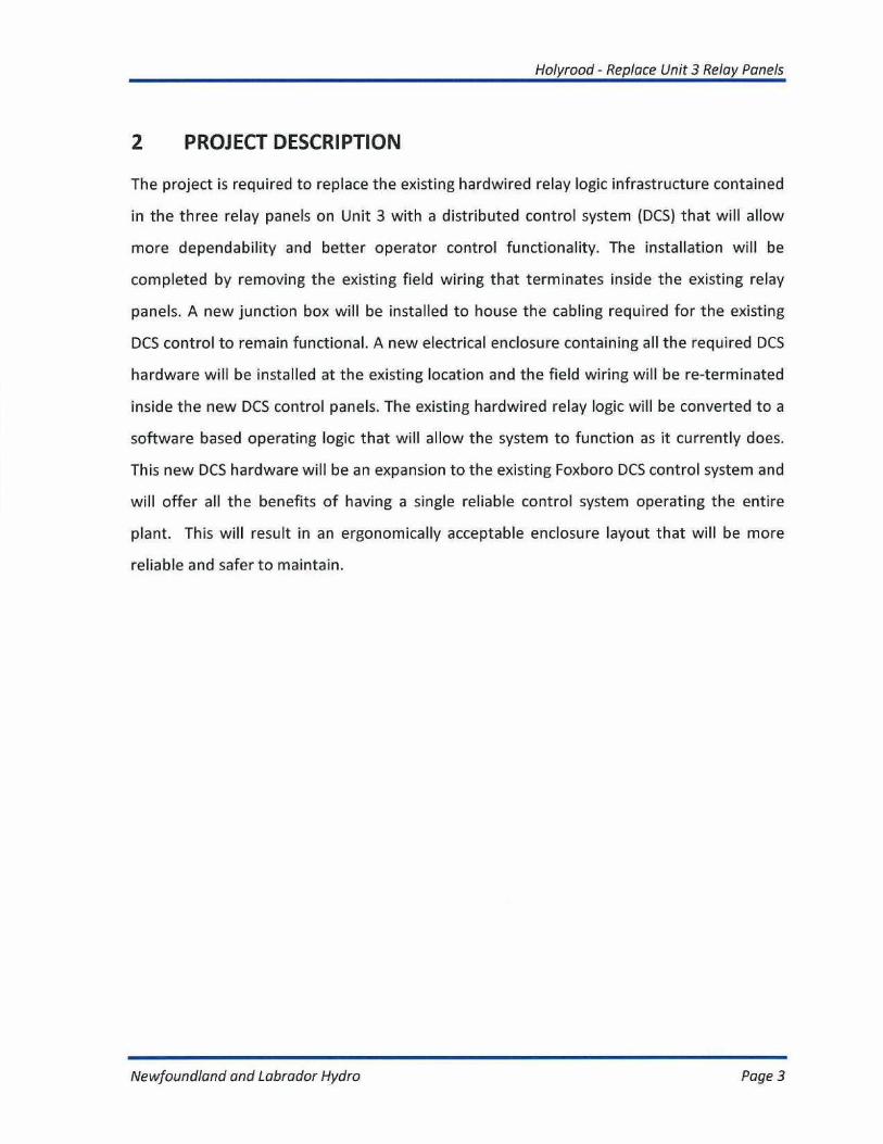
The project is required to replace the existing hardwired relay logic infrastructure contained
in the three relay panels on Unit 3 with a distributed control system (DCS) that will allow
more dependability and better operator control functionality. The installation will be
completed by removing the existing field wiring that terminates inside the existing relay
panels. A new junction box will be installed to house the cabling required for the existing
DCS control to remain functional. A new electrical enclosure containing all the required DCS
hardware will be installed at the existing location and the field wiring will be re-terminated
inside the new DCS control panels. The existing hardwired relay logic will be converted to a
software based operating logic that will allow the system to function as it currently does.
This new DCS hardware will be an expansion to the existing Foxboro DCS control system and
will offer all the benefits of having a single reliable control system operating the entire
plant. This will result in an ergonomically acceptable enclosure layout that will be more
reliable and safer to maintain.
Newfoundland and Labrador Hydro
Page 3
Holyrood - Replace Unit 3 Relay Panels
3
EXISTING SYSTEM
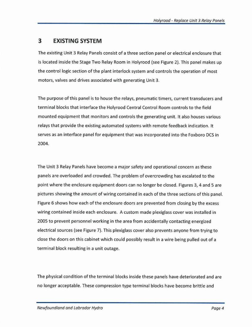
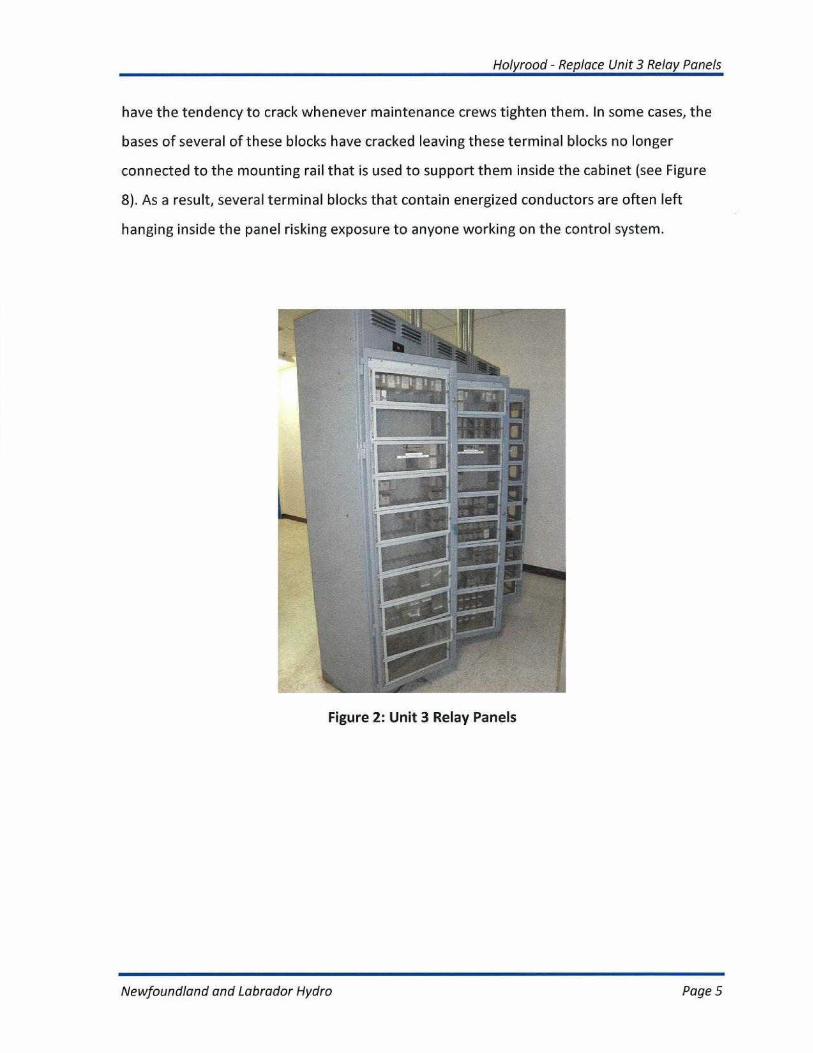
The existing Unit 3 Relay Panels consist of a three section panel or electrical enclosure that
is located inside the Stage Two Relay Room in Holyrood (see Figure 2). This panel makes up
the control logic section of the plant interlock system and controls the operation of most
motors, valves and drives associated with generating Unit 3.
The purpose of this panel is to house the relays, pneumatic timers, current transducers and
terminal blocks that interface the Holyrood Central Control Room controls to the field
mounted equipment that monitors and controls the generating unit. It also houses various
relays that provide the existing automated systems with remote feedback indication. It
serves as an interface panel for equipment that was incorporated into the Foxboro DCS in
2004.
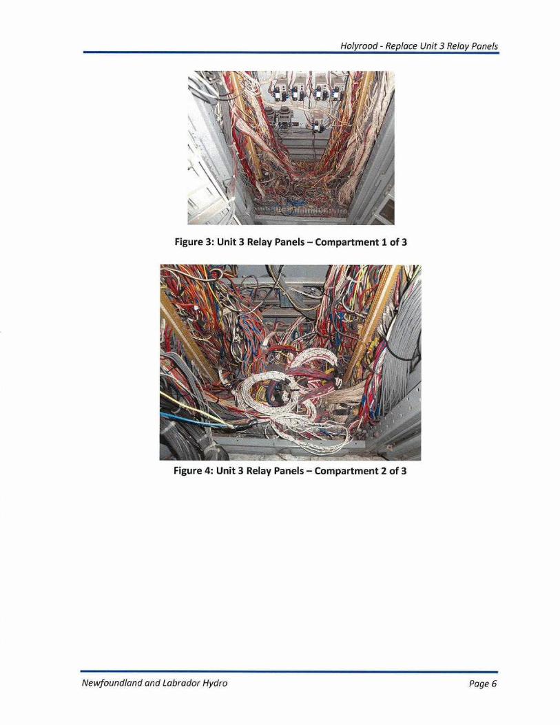
The Unit 3 Relay Panels have become a major safety and operational concern as these
panels are overloaded and crowded. The problem of overcrowding has escalated to the
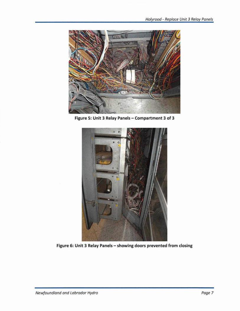
point where the enclosure equipment doors can no longer be closed. Figures 3, 4 and 5 are
pictures showing the amount of wiring contained in each of the three sections of this panel.
Figure 6 shows how each of the enclosure doors are prevented from closing by the excess
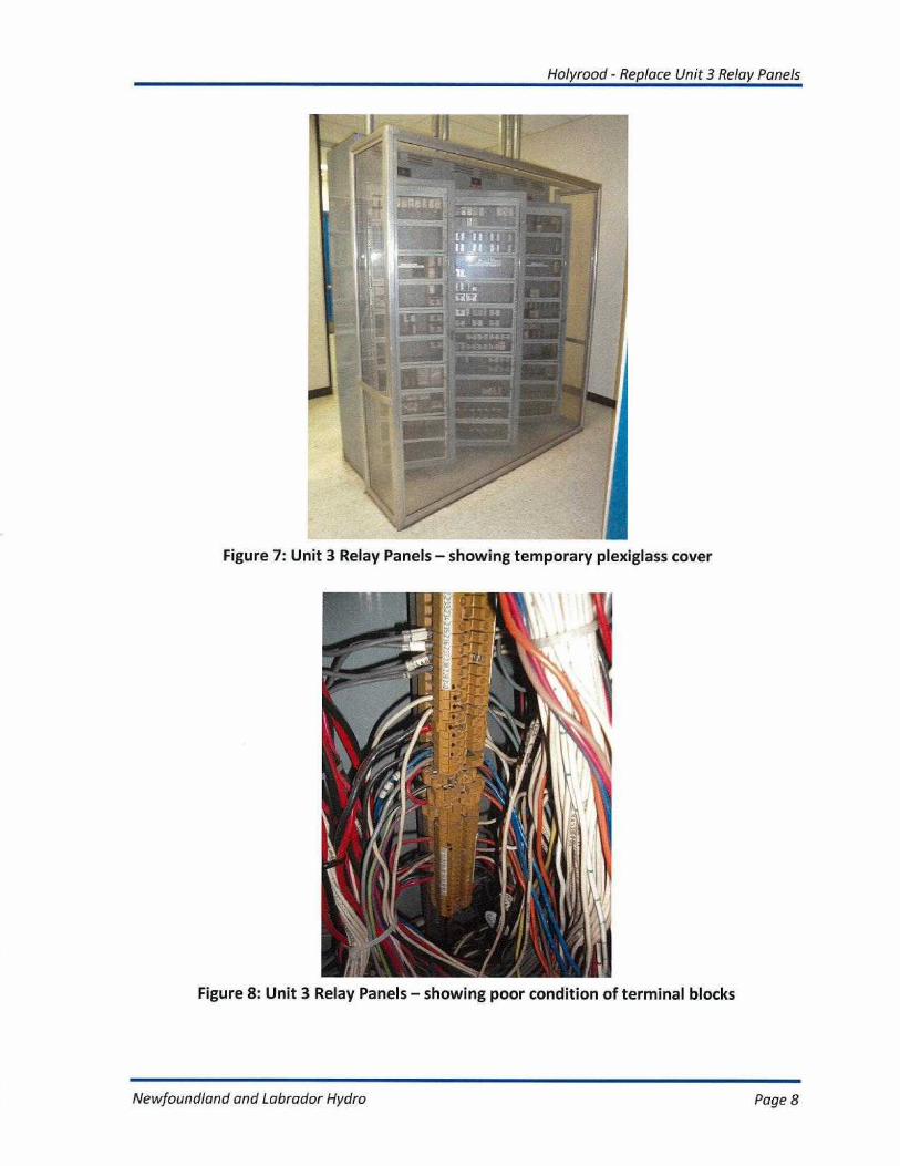
wiring contained inside each enclosure. A custom made plexiglass cover was installed in
2005 to prevent personnel working in the area from accidentally contacting energized
electrical sources (see Figure 7). This plexiglass cover also prevents anyone from trying to
close the doors on this cabinet which could possibly result in a wire being pulled out of a
terminal block resulting in a unit outage.
The physical condition of the terminal blocks inside these panels have deteriorated and are
no longer acceptable. These compression type terminal blocks have become brittle and
Newfoundland and Labrador Hydro
Page 4
Holyrood - Replace Unit 3 Relay Panels
have the tendency to crack whenever maintenance crews tighten them. In some cases, the
bases of several of these blocks have cracked leaving these terminal blocks no longer
connected to the mounting rail that is used to support them inside the cabinet (see Figure
8). As a result, several terminal blocks that contain energized conductors are often left
hanging inside the panel risking exposure to anyone working on the control system.
Figure 2: Unit 3 Relay Panels
Newfoundland and Labrador Hydro
Page 5
Holyrood - Replace Unit 3 Relay Panels
Figure 3: Unit 3 Relay Panels - Compartment 1 of 3
Figure 4: Unit 3 Relay Panels - Compartment 2 of 3
Newfoundland and Labrador Hydro
Page 6
Holyrood - Replace Unit 3 Relay Panels
Figure 5: Unit 3 Relay Panels - Compartment 3 of 3
Figure 6: Unit 3 Relay Panels - showing doors prevented from closing
Newfoundland and Labrador Hydra
Page 7
Holyrood - Replace Unit 3 Relay Panels
Figure 7: Unit 3 Relay Panels - showing temporary plexiglass cover
Figure 8: Unit 3 Relay Panels - showing poor condition of terminal blocks
Newfoundland and Labrador Hydro
Page 8
Holyrood - Replace Unit 3 Relay Panels
3.1 Age of Equipment or System
The Unit 3 Relay Panels were installed in 1978 and commissioned in the spring of 1979
when Stage Two came on line.
3.2 Major Work and/or Upgrades
There have been no major upgrades to the existing Unit 3 Relay Panels since they were
installed in 1978. There have been, however, additions to this panel over the years that
have caused overcrowding to the point that the enclosure doors will no longer close. These
additions include the installation of several motor current transducers in 1993 when the
original Unit 3 control system was converted to a Westinghouse DCS. There have also been
other minor operating logic changes and alarm installations since 1993.
In addition, in 2004, the plant changed the Westinghouse DCS into a Foxboro DCS platform.
At that time, several relays were removed from this panel and placed in the DCS logic. As a
result of this upgrade, new cables had to be installed and terminated in these cabinets
making the cabinets overcrowded and untidy.
3.3 Anticipated Useful life
The Unit 3 Relay Panels is composed mainly of terminal blocks, electromechanical relays
and timers that have an estimated life span of 25 years.
3.4 Maintenance History
Hydro does not separately track maintenance costs for the relay panels. Maintenance costs
for the Unit 3 Relay Panels are included in the costs of other electrical systems.
Newfoundland and Labrador Hydro
Page 9
Ho/yrood - Replace Unit 3 Relay Panels
3.5 Outage Statistics
There have been no outages directly related to the Unit 3 Relay Panels. However, as this
panel serves as one of the main interface panels to the existing DCS and the plant
equipment, due to the current condition of the panel and the overcrowding of wires, the
panel is considered by Hydro to be a major risk that could lead to an outage on Unit 3.
3.6 Industry Experience
The industry standard is that every electrical enclosure should be designed and sized to
allow for safe access and easy troubleshooting of individual electrical components to enable
performance, reliability, and maintainability of any electrical system.
Utilities are upgrading the older relay based electrical control systems to programmable or
distributed logic control systems. These newer systems offer fault tolerant designs that can
remain operational despite a single point fault failure. In addition, they have a smaller
footprint design, provide easier maintenance and allows for future logic changes without
having to make wiring changes.
3.7 Maintenance or Support Arrangements
The Unit 3 Relay Panels are maintained by Hydro. In the event of a failure, there are
currently no maintenance or support arrangements in place to provide assistance on the
existing control system. However, after this upgrade, the existing service agreement with
Invensys Systems (Foxboro) will cover the new control system for continued operational
support. Hydro personnel will have unlimited access to the Foxboro system support
program, remote system support, and ten hours of on site support per year as well as
Newfoundland and Labrador Hydro
Page 10
Holyrood - Replace Unit 3 Relay Panels
reduced training cost benefits.
3.8 Vendor Recommendations
Invensys Systems, the manufacturer of the existing plant wide DCS control system,
recommends replacing the Unit 3 Relay Panels by moving the hardwired logic into the
existing plant DCS platform.
3.9 Availability of Replacement Parts
Replacement parts are readily available for the existing Unit 3 Relay Panels.
3.10 Safety Performance
The Unit 3 Relay Panels are considered by Hydro as being a significant safety hazard. The
sub standard condition of these panels resulted in the submittal of a safe workplace
observation program (SWOP) condition. The results of the investigation into this condition
revealed that the panels contain sub-standard or poor wiring that present shock hazards to
personnel working inside these panels. It also revealed that the amount of wiring located
inside these panels will impede or delay future maintenance.
Rule number 2-118 of the Canadian Electrical Code states that "Electrical equipment shall
be installed as to ensure that after installation there is ready access to nameplates and
access to parts requiring maintenance". Rule number 12-3034 (2)(a)(ii) of the Canadian
Electrical Code states that enclosures identified shall be only permitted to be used as
junction boxes "where wiring is being added to an enclosure forming part of an existing
Newfoundland and Labrador Hydro
Page 11

Holyrood - Replace Unit 3 Relay Panels
installation and the conductors, splices and taps do not fill the wiring space at any cross
section to more than 75 percent of the cross sectional area of the space". Rule 11.2.1.1 of
the National Fire Protection Association (NFPA) 79 Electrical Standard for Industrial
Machinery states that "Ail items of control equipment shall be placed and oriented so that
they can be identified without moving them or the wiring. " Rule 11.2.1.2 of this same code
states that terminal blocks shall be mounted to provide unobstructed access to the
terminals and their conductors. As a result of these deficiencies, it is evident that the
condition of the Unit 3 Relay Panels does not meet Canadian Electrical Code or other
electrical standards and is thus a potential safety hazard to anyone working inside these
enclosures.
In addition to the code deficiencies outlined above, the physical condition of the terminal
blocks located inside the panels have deteriorated and are no longer acceptable. These
compression type terminal blocks have become brittle and have the tendency to crack
whenever maintenance crews tighten them. In some cases the bases of several of these
blocks have cracked leaving these terminal blocks no longer connected to the mounting rail
that is used to support them inside the cabinet. As a result, terminal blocks that contain
energized conductors are often found floating inside the panel risking exposure to workers.
The plant standard for Electrical Equipment Enclosures (standard MSTD-059) states that
enclosures shall be National Electrical Manufacturers Association (NEMA) 12 rated or
greater when installed in any area of the plant not exposed to damp or corrosive
environments. NEMA 12 is a standard from the National Electrical Manufacturers
Association, which defines enclosures with protection against dirt, dust, splashes by non-
corrosive liquids, and salt spray. The panels do not meet this requirement, since the doors
of the enclosures will no longer close. As a result, air borne dust, fibers or splashing water is
free to enter these enclosures. In addition, since the doors of these enclosures no longer
Newfoundland and Labrador Hydro
Page 12
Holyrood - Replace Unit 3 Relay Panels
close, if an electrical fire was to occur inside these panels, it would spread to the
surrounding areas with the possibility of causing significant equipment damage and
personnel injury or death. Although the plexiglass barrier does provide some additional
protection, it is a temporary installation that does not meet Hydro standards.
3.11 Environmental Performance
There are no environmental issues associated with the existing relay panels.
3.12 Operating Regime
Unit 3 has the capability to operate in generation or synchronous condense modes. This
unit operates predominately in the generation mode in the winter and in synchronous
condense mode for summer months to provide voltage support to the Island
Interconnected System.
The controls in the Unit 3 Relay Panels are vital to the operation of the generating unit
whether it is in generation or synchronous condense mode. In addition, there are relays and
wiring contained in this panel that monitor and control auxiliary functions of the turbine
that are required even when the generating unit is not in service. The relay panels are
essential to the daily operation of the plant whether or not Unit 3 is operating.
Newfoundland and Labrador Hydro
Page 13
Holyrood - Replace Unit 3 Relay Panels
4
JUSTIFICATION
This project is justified on the need to replace sub-standard equipment and eliminate safety
hazards. Unit 3 Relay Panels are overcrowded with wiring which prevents the doors from
being able to close. There is a risk of an electrical fire occurring inside the panels that could
spread to the surrounding areas of the plant leading to significant equipment damage and
potential personnel injury or death.
There are several direct violations of the Canadian Electrical Code and other applicable
standards pertaining to the condition of these panels. In addition, the plant maintenance
personnel have identified the panels as an area of significant safety concern and expressed
direct concerns about working inside these panels.
As a result of the age of these panels and the amount of wiring contained inside them, the
terminal blocks that are used to terminate energized conductors inside the panel have
become very brittle. This has lead to them cracking in the areas that hold the conductors
and on the bases that hold the block to the mounting rail inside the panel. As a result,
energized terminal blocks are hanging inside the panel. In addition, maintenance crews
have also found non terminated energized conductors inside this enclosure.
Also, by integrating the relay controls into the existing DCS system, the future availability of
Unit 3 will be improved. The Foxboro DCS control system offers a fault tolerant design and a
redundant communication network that will continue to operate despite a single point
failure. The proposed upgrade will also allow easier system troubleshooting after a failure
and offers the advantage of being able to make future changes in software as opposed to
Newfoundland and Labrador Hydro
Page 14
Holyrood - Replace Unit 3 Relay Panels
having to make physical wiring changes.
4.1 Net Present Value
A net present value analysis was not performed considering two alternatives. Please see
section 4.3 `Cost Benefit Analysis' for details.
4.2 Levelized Cost of Energy
A levelized cost of energy analysis is not applicable since no new generation sources are
being evaluated.
4.3 Cost Benefit Analysis
The following two viable alternatives were evaluated in a cost benefit analysis:
• Alternative 1: Replacement with DCS System. Replace the existing relay panels and
relay logic with a new panel equipped with a DCS controlled system (total proposed
capital cost of $830,700);
• Alternative 2: Replacement with Electromechanical Relays. Replace the existing relay
panels and relay logic with a new relay panel equipped with electromechanical
relays (total proposed capital cost of $676,500).
These two alternatives were evaluated using a cost benefit analysis. The analysis included
the following assumptions:
• The study period for the cost benefit analysis is 25 years, (2012 to 2037).
• Electromechanical relays have an anticipated useful life of 25 years.
• The DCS option has an anticipated useful life of 15 years and carries an additional
cost of $75,000 in year 2027 to replace any obsolete hardware after the 15 years.
Newfoundland and Labrador Hydro
Page 15
Holyrood - Replace Unit 3 Relay Panels
• To assure that both alternatives are compared equally, it is assumed that 1/3 of the
value remaining in the DCS system hardware to be installed in 2027 can be
recovered at the end of 25 years (2037) since it has an anticipated lifespan of 15
years and has only been in service for ten years.
• $3,500 per annum is allowed for engineering to investigate electrical faults in the
electromechanical relay alternative since there would be no single common plant
wide control system equipped with Sequence of Events monitoring.
+ $4,100 per annum after year ten is allowed for maintenance work in the
electromechanical relay alternative.
• An extra $50,000 every ten years is allowed for completing wiring changes inside the
electromechanical relay panels for major upgrades that require significant rewiring
as opposed to simple logic changes required if the DCS alternative was installed.
+ Electromechanical relays do not offer internal diagnostics that quickly indicate the
source of a failure. In the event of an outage of unit 3 prior to 2020, as a result of an
electromechanical relay failure, requiring the gas turbines to be dispatched for 15
hours would cause the cost benefit analysis to be in a virtual break even position.
Using the average required gas turbine energy values for this period (637 MWh) it
was determined that the incremental cost of fuel for gas turbine operation over the
No. 6 Heavy oil which is burned in Holyrood, will result in an additional cost of
$93,668 in the electromechanical relay option.
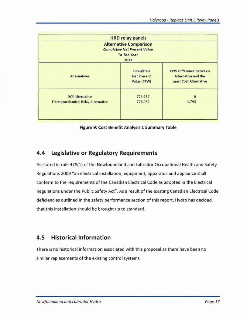
Using these assumptions, the results of the cost benefit analysis showed that the
Electromechanical Relay Alternative is slightly more expensive over the 25 year anticipated
useful life of the project. Figure 9 shows the results.
Newfoundland and Labrador Hydro
Page 16
Holyrood - Replace Unit 3 Relay Panels
HRD relay panelsAlternative ComparisonCumulative Net Present Value
To The Year
2037
Alternatives
Cumulative
Net Present
Value [CPW[
CPW Difference between
Alternative and the
Least Cost Alternative
DCS Alternative
Electromechanical Relay Alternative
776,237
778,032
0
1.795
Figure 9: Cost Benefit Analysis 1 Summary Table
4.4 Legislative or Regulatory Requirements
As stated in rule 478(1) of the Newfoundland and Labrador Occupational Health and Safety
Regulations 2009 "an electrical installation, equipment, apparatus and appliance shall
conform to the requirements of the Canadian Electrical Code as adopted in the Electrical
Regulations under the Public Safety Act". As a result of the existing Canadian Electrical Code
deficiencies outlined in the safety performance section of this report, Hydro has decided
that this installation should be brought up to standard.
4.5 Historical Information
There is no historical information associated with this proposal as there have been no
similar replacements of the existing control systems.
Newfoundland and Labrador Hydro
Page 17
Holyrood - Replace Unit 3 Relay Panels
4.6 Forecast Customer Growth
Forecast customer growth has no impact on this project.
4.7 Energy Efficiency Benefits
There are no energy efficiency benefits associated with upgrading the existing relay control
panels.
4.8 Losses during Construction
There will be no anticipated energy losses while upgrading the existing control systems. The
electrical controls in the panels will be integrated into the Foxboro DCS during the planned
annual outage.
4.9 Status Quo
The status quo relay based control system is not an acceptable alternative. Due to safety
concerns with the existing system, the age and condition of the equipment, the relay panels
need to be replaced.
4.10 Alternatives
When evaluating this project, Hydro has considered the following two alternatives:
+ Replacement of the existing relay panels and relay logic with a new panel equipped
with a DCS controlled system (total proposed capital cost of $830.7K);
Newfoundland and Labrador Hydro
Page 18
Holyrood - Replace Unit 3 Relay Panels
• Replacement of the existing relay panels and relay logic with a new panel
equipped with electromechanical relays (total proposed capital cost of $676,500).
Despite the fact that the upfront capital cost of the DCS alternative is more than
the electromechanical relay alternative, in the event of a single electromechanical
relay failure that results in Unit 3 becoming unavailable, the DCS alternative
becomes the more cost effective option. As a result of this fact and the following
benefits gained with going with the DCS alternative, Hydro has decided to proceed
with the DC5 alternative:
• Overall safer system since maintenance and troubleshooting can be completed
from the safety of the control room - The DCS system allows maintenance crews
to observe the status of input and outputs from an engineering workstation
located inside the control room. However, in the electromechanical relay
alternative, maintenance crews would have to work inside energized electrical
panels when trying to perform maintenance and troubleshoot problems.
• More dependable system as solid state relays contain no moving parts -• DCS
outputs operate using an electronic switch or transistor which contains no moving
parts. As a result, fewer faults will occur on the DCS system which will result in
more dependable operation of the Unit 3 generator;
• Easier troubleshooting capabilities since there is less wiring and electrical
components to fail - In the event that an electromechanical relay was to fail,
several hours or possibly days would be spent trying to determine the source of
the problem. This will lead to extended system unavailability or possibly a Unit 3
outage. The DCS alternative offers built in internal diagnostics, that will alert
operators of a problem immediately;
• Built in fault tolerance that can accept some single point control system failures
- Since the DCS option contains redundant processors and communications, the
Newfoundland and Labrador Hydro
Page 19
Holyrood - Replace Unit 3 Relay Panels
system will continue to operate despite a failure on any of these critical
components;
• Smaller equipment footprint that frees up valuable plant real estate - When
replacing the existing system with electromechanical relays, a much larger panel
would be required to house all the relays and wiring than what would be required
if the DCS alternative was used. Currently, there is very little extra room inside the
Stage 2 relay room for a larger enclosure;
• Easier future upgrade capabilities that will not involve wiring changes for simple
logic changes - The DCS alternative will allow technicians to make simple logic
changes by re-configuring software as opposed to spending hours or days re-
wiring relays. In addition, it will allow more complicated logic processes to be
installed in the event that any future plant upgrades take place. The
electromechanical relay option only supports discrete relay logic and does not
offer any advanced control capabilities such as analog inputs, analog outputs,
closed loop control, accurate timing functions and counting functions;
• Reduced commissioning time required to fix errors as small logic changes are
made much easier in software than in hardwired systems - If during
commissioning, any logic changes are required, the DCS alternative will allow these
changes to be made without having to change any of the wiring or equipment
inside the panel. However, if changes are required when using the
electromechanical relay alternative, this could result in hours or days of re-wiring
and if the change is significant enough, there may not be any extra space inside
the panel to add extra relays;
• Better automation capabilities and much faster control processing speeds
available in DCS controlled system - The DCS alternative will allow engineering to
program alarms and other automation logic into the system that will inform
Newfoundland and Labrador Hydro
Page 20

Holyrood - Replace Unit 3 Relay Panels
operators when something has gone wrong in the process. It will also operate at
much faster speeds than relay logic allowing the process to respond to changes
much faster than they currently do;
+ Common plant wide control system that allows operators to analyze faults and
historically trend and display any information required -The existing DCS is
equipped with sequence of events recording capabilities and historical trending of
all inputs and outputs. These features will allow operators and engineering to
quickly analyze faults and disturbances by knowing exactly what events occurred
at the time of a fault.
• DCS system allows for remote monitoring and control of systems via HMI
computers or operator workstations -The DCS alternative will allow the
operators inside the control room to see the entire process on one Human
Machine Interface (HMI) computer screen. This system will allow automatic
alarming capabilities and will reduce the amounts of lights, switches and
pushbuttons currently installed inside the control room. It will therefore
streamline the operation of the process and will reduce the chances of operator
error. In addition, it will allow future control room modernization to take place
without having to replace any of these systems.
Newfoundland and Labrador Hydro
Page 21
Holyrood - Replace Unit 3 Relay Panels
5
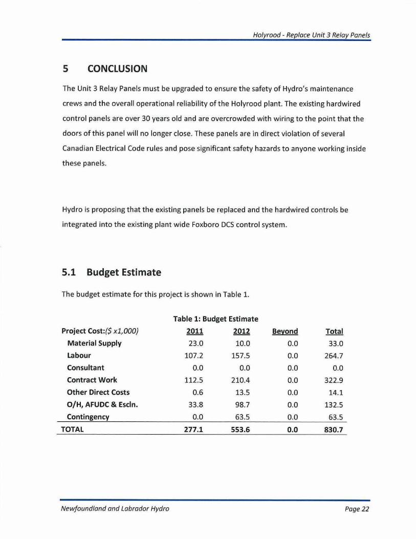
CONCLUSION
The Unit 3 Relay Panels must be upgraded to ensure the safety of Hydro's maintenance
crews and the overall operational reliability of the Holyrood plant. The existing hardwired
control panels are over 30 years old and are overcrowded with wiring to the point that the
doors of this panel will no longer close. These panels are in direct violation of several
Canadian Electrical Code rules and pose significant safety hazards to anyone working inside
these panels.
Hydro is proposing that the existing panels be replaced and the hardwired controls be
integrated into the existing plant wide Foxboro DCS control system.
5.1 Budget Estimate
The budget estimate for this project is shown in Table 1.
Table 1: Budget Estimate
Project Cost:($ x1,000) 2011 2012 Beyond Total
Material Supply 23.0 10.0 0.0 33.0
Labour 107.2 157.5 0.0 264.7
Consultant 0.0 0.0 0.0 0.0
Contract Work 112.5 210.4 0.0 322.9
Other Direct Costs 0.6 13.5 0.0 14.1
O/H, AFUDC & Escln. 33.8 98.7 0.0 132.5
Contingency 0.0 63.5 0.0 63.5
TOTAL 277.1 553.6 0.0 830.7
Newfoundland and Labrador Hydro
Page 22
Holyrood - Replace Unit 3 Relay Panels
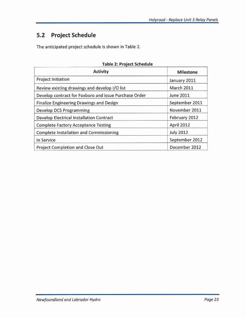
5.2 Project Schedule
The anticipated project schedule is shown in Table 2.
Table 2: Project Schedule
Activity Milestone
Project Initiation January 2011
Review existing drawings and develop I/O list March 2011
Develop contract for Foxboro and issue Purchase Order June 2011
Finalize Engineering Drawings and Design September 2011
Develop DCS Programming November 2011
Develop Electrical Installation Contract February 2012
Complete Factory Acceptance Testing April 2012
Complete Installation and Commissioning July 2012
In Service September 2012
Project Completion and Close Out December 2012
Newfoundland and Labrador Hydro
Page 23