Embed Size (px)
Citation preview

Form RZ-NA P-RA/RAD/RV, Page 1
Parts Form RZ-NA P-RA/RAD/RV (Version A)
Obsoletes Form RZ-NA P-RA/RAD/RV
Replacement Parts for
Used Oil Heaters
IMPORTANT1. Always include complete heater model and serial number so
that any specification change can be considered for partsshipment. It can save time and expense.
2. Used oil heaters are not approved for sale in the states ofCalifornia and New Jersey.
3. We reserve the right to substitute functional replacements.4. Specifications are subject to change without notice.
APPLIES TO: Models RA/RAD 110, 140,
235, 350, 500 and RV 225, 325
Model/Size Date of Introduction DiscontinuedRA/RAD110 UL - 6/90 (APF) 6/92 (ARF)
Model/SizeRA/RAD140
Date of IntroductionUL & CSA - 6/92 (ARF)
Model/Size RA/RAD235
Date of IntroductionUL - 6/90 (APF)CSA - 1/92 (ARA)
Model/SizeRA/RAD350
Date ofIntroductionCSA - 12/93 (ASL)
Model/SizeRA/RAD500
Date of IntroductionCSA - 7/97 (AWG)
Model/SizeRV 225 andRV 325
Date of IntroductionCSA - 11/02 (BBK)
Index by Page No. RA RAD RV
Air Compressor 7 7 7
Air Manifold Components 7 7 7
Backflow Sensor Limit Control 10 10 10
Belt -- 16 18
Blower and Components -- 16 18
Burner and Components 4 4 4
Cabinet Parts (Outer) 14-16 14-17 18
Cleaning Brush or Rake 23 23 23
Door Panels (inner access doors) 20-21 20-21 22
Draft Regulator 14 14 18
Drive Components -- 16 18
Electrical Boxes and Components 10 10 10
Electrodes 4 4 4
Fan and Components 16 -- --
Fan and Limit Controls (Heater) 12 12 13
Filter (Compressed Air) 7 7 7
Filter (Fuel) - Supply Line 8 8 8
Gaskets (for inner access doors) 20-21 20-21 22
Gasket (for burner assembly) 4 4 4
Hanger Kit (Same as Option CK10) 23 23 23
Heat Exchanger/Combustion Chamber
Assembly20-21 20-21 22
Heat Exchanger (fuel-preheater) and
Controls3 3 3
High Altitude Kits 8 8 8
Hour Meter 8 8 8
Ignition Controller 4 4 4
Limit Controls (Oil Temperature) 3 3 3
Limit and Fan Controls 12 12 13
Motor, Fan or Blower 16 16 18
Motor, Gear (at the Remote Pump) 8 8 8
Nozzle 6 6 6
Paint 23, 24 23, 24 23, 24
Pressure Switch 10 10 10
Pump (Remote) 8 8 8
Serial Number 2 2 2
Stand (Heater Stand Option ST-1 for
Reznor Model OT-250 Fuel Tank)24 -- 24
Strainer Assembly (fuel line) 5 5 5
Switch (Control/Disconnect) 10 10 10
Thermostat 23 23 23
Transformer 10 10 10
Vacuum Gauge 8 8 8
Valve, Foot 8 8 8
Valve, Relief 8 8 8
Valve Solenoid 5 5 5
Vent Cap 14 14 18
Vertical Louvers 23 23 23
®
IMPORTANT: Effective 1/20/05, Size 500 was changed toa 240V 3-wire system. The cartridge heaters, air com-pressor, burner, and hour meter were changed from 240Vcontrols to 115V. Select replacement parts carefully.

Form RZ-NA P-RA/RAD/RV, Page 2
First Element of the Serial Number - Date of ManufactureYear Jan Feb Mar Apr May June July Aug Sept Oct Nov Dec
1990 APA APB APC APD APE APF APG APH API APJ APK APL
1991 AQA AQB AQC AQD AQE AQF AQG AQH AQI AQJ AQK AQL
1992 ARA ARB ARC ARD ARE ARF ARG ARH ARI ARJ ARK ARL
1993 ASA ASB ASC ASD ASE ASF ASG ASH ASI ASJ ASK ASL
1994 ATA ATB ATC ATD ATE ATF ATG ATH ATI ATJ ATK ATL
1995 AUA AUB AUC AUD AUE AUF AUG AUH AUI AUJ AUK AUL
1996 AVA AVB AVC AVD AVE AVF AVG AVH AVI AVJ AVK AVL
1997 AWA AWB AWC AWD AWE AWF AWG AWH AWI AWJ AWK AWL
1998 AXA AXB AXC AXD AXE AXF AXG AXH AXI AXJ AXK AXL
1999 AYA AYB AYC AYD AYE AYF AYG AYH AYI AYJ AYK AYL
2000 AZA AZB AZC AZD AZE AZF AZG AZH AZI AZJ AZK AZL
2001 BAA BAB BAC BAD BAE BAF BAG BAH BAI BAJ BAK BAL
2002 BBA BBB BBC BBD BBE BBF BBG BBH BBI BBJ BBK BBL
2003 BCA BCB BCC BCD BCE BCF BCG BCH BCI BCJ BCK BCL
2004 BDA BDB` BDC BDD BDE BDF BDG BDH BDI BDJ BDK BDL
2005 BEA BEB BEC BED BEE BEF BEG BEH BEI BEJ BEK BEL
2006 BFA BFB BFC BFD BFE BFF BFG BFH BFI BFJ BFK BFL
2007 BGA BGB BGC BGD BGE BGF BGG BGH BGI BGJ BGK BGL
2008 BHA BHB BHC BHD BHE BHF BHG BHH BHI BHJ BHK BHL
2009 BIA BIB BIC BID BIE BIF BIG BIH BII BIJ BIK BIL
2010 BJA BJB BJC BJD BJE BJF BJG BJH BJI BJJ BJK BJL
2011 BKA BKB BKC BKD BKE BKF BKG BKH BKI BKJ BKK BKL
2012 BLA BLB BLC BLD BLE BLF BLG BLH BLI BLJ BLK BLL
2013 BMA BMB BMC BMD BME BMF BMG BMH BMI BMJ BMK BML
2014 BNA BNB BNC BND BNE BNF BNG BNH BNI BNJ BNK BNL
2015 BOA BOB BOC BOD BOE BOF BOG BOH BOI BOJ BOK BOL
2016 BPA BPB BPC BPD BPE BPF BPG BPH BPI BPJ BPK BPL
2017 BQA BQB BQC BQD BQE BQF BQG BQH BQI BQJ BQK BQL
Rating Plate and Serial No. Rating Plate Key
A = Model NO.
B = Horsepower
C = Amps
D = Minimum Circuit Ampacity
E = Maximum Unit Fuse
F = Altitude Range (feet)
G = Firing Rate (adjusted for altitude)
H = Input Rate (adjusted for altitude)
I = Maximum Overfire Pressure
(" w.c.)
J = External Static Pressure (" w.c.)
Serial No. Decoding
○ ○ ○ ○ ○ ○ ○ ○ ○ ○ ○ ○ ○ ○ ○ ○ ○ ○ ○ ○ ○
Sample ARK 350 A 00000
Codes 1 2 3 4
Key: 1 Date of manufacture (see chart below)
2 Size (BTUH input)
3 A = Fan Model; D = Blower Model
4 Consecutive Number
K = Flue Outlet Pressure Range
(" w.c.)
L = Top Clearance (inches)
M = Rear Clearance (inches)
N = Bottom Clearance (inches)
O = Front Clearance (inches)
P = Side Clearance (inches)
Q = Flue Pipe Clearance (inches)
R = RAD and RV may be used
with a discharge duct; RA
may not be used with a dis-
charge duct.
REFERENCES: Form RZ-NAReplacement Parts for Discontinued 760-1
Models RA/RAD118/230
Installation/Maintenance - RA/RAD 140/235 I-RA/D 140/235
Installation/Maintenance - RA/RAD 350/500 I-RA/D 350/500
Installation/Maintenance - RV 225/325 I-RV
Heater Stand for Model OT Oil Tank I-OIL-HS
High Altitude Conversion - Size 235 461-HA
High Altitude Conversion - Size 350 464-HA
WEBSITE: www.ReznorHeaters.com
REZNORM ERCER,PA.,U.S.A.16137
M ULTI-OIL-FIRED UNIT HEATER
CSA CERTIFIED TO UL STANDARD 296A
FO R INDUSTRIAL/CO M M ERCIAL USE O NLY
FO R USE W ITH INTEG RAL G RO UP 1 O R 2 PRIM ARY SAFETY CO NTRO LS.
SUITABLE FO R NO .2 FUEL AND USED O IL RANG ING FRO M ATF TO SAE 50.
M O DEL [ A ]
SERIAL NO . ARK350A0000 [ B ]HP
USE CO PPER CO NDUCTO RS O NLY
115 VO LTS 1 PH 60 HZ [ C ]AM PS
M INIM UM CIRCUIT AM PACITY [ D ]AM PS
M AXIM UM UNIT FUSE [ E ]AM PS
FO R USE AT [ F ] FEET
FIRING RATE [ G ]G .P.H.
INPUT [ H ]BTU/HR
O UTPUT DEPENDS O N BTU CO NTENT O F USED O IL.
M AXIM UM O VERFIRE PRESSURE [ I ]IN.W .C.
EXTERNAL STATIC PRESSURE [ J ]IN.W .C.
FLUE O UTLET PRESSURE RANG E (DRAFT) [ K ]IN.W .C.
THIS UNIT IS FO R INSTALLATIO N SUSPENDED FRO M A CEILING
W ITH CLEARANCES TO CO M BUSTIBLES M ATERIALS NO LESS THAN...
TO P -[ L ]" BO TTO M -[ N ]" SIDES -[ P ]"
REAR -[ M ]" FRO NT -[ O ]" FLUE PIPE -[ Q ]"
IN CANADA,REFERENCE CSA B139-M 91 FO R INSTALLATIO N IN G ARAG ES,ETC.
IN USA,INSTALL UNIT IN ACCO RDANCE W ITH THE FO LLO W ING STANDARDS;
ANSI/NFPA 409-1990 FO R AIRCRAFT HANG ARS
ANSI/NFPA 88A-1991 FO R PARKING STRUCTURES
ANSI/NFPA 88B-1991 FO R REPAIR G ARAG ES
THIS UNIT [ R ]W ITH AIR DUCTS.
THIS UNIT IS NO T FO R USE W ITH AIR FILTERS.
REPLACEM ENT NO ZZLES M UST BE PURCHASED FRO M REZNO R
PATENT U.S.5,080,579

Form RZ-NA P-RA/RAD/RV, Page 3
Fuel Pre-Heater System (U.S. Patent No. 5,080,579) - All Models
Oil Pre-heating System (U. S. Patent No. 5,080,579)
1 Wire andCable
109
3(Corner of the box covering the end and
part of the front)
5
FlexibleFuel Line,
P/N 107164
2 (Front only)
Top View
Pre-heater is located in the box belowand behind the burner assembly
7 - Low Oil TemperatureLimit (black wire)
8 - Manual Reset High OilTemperature Limit
(yellow wire)
11 -HeaterFrontSupport
9 - Heating Element
Brass Elbow,P/N 110291
To remove the heating element,remove the heater front support
and pull heating elementforward.
6 - Oil Temperature Control (blue wire)
7 (yellow dot)6 (whitedot)
89
11
"Old"stylelimits
5A - "O" Ring
11 - HeaterFront Support
Oil is heated as it flows aroundthe cylinder
5
Cylinder Cover
RA/RAD RV
110/140/235 350 500 225/325
Fuel Heat Exchanger Assembly Components
1 Fuel Heat Exchanger Box (less Codes 2 and 3)
2 Fuel Heat Exchanger Box Front
3 Fuel Heat Exchanger Box Corner
4 Band (from heat exchanger box around burner tube) - not shown
5 Oil Primary Heater Assembly (includes 2-piece aluminum
cylinder, end cap, and "O" ring, Code 5A)
5A Replacement "O" ring for Oil Heater cylinder
6 Oil Temperature Control, 170°, Honeywell 2455RPV8755002
7 Low Oil Temperature Limit, 155°, Honeywell 2455RPV8755003
8 High Oil Temperature limit, 220°, Honeywell 2455RPV8755001
9 Heater, Hotwatt #SC75-6 106953 129384 209190, 120V (beginning 1/20/05) 106953
300 Watt 157048, 230V (prior to 1/20//05)
770 Watt
10 Copper/Brass Pipe, 1/8" NPT x 2-1/2" long
11 Heater Front Support
107122
104787
210761 (replaces 105318)
650
Watt
300
Watt
104784
104788
104789
179313
210762 (replaces 105319)
210763 (replaces 105320)
Co
de
Description
101916
132224

Form RZ-NA P-RA/RAD/RV, Page 4
Burner - Models RA, RAD, and RV
29
25
BurnerJunctionBox
Main Electrical Box
* Model 110 requires low fire baffle, P/N 107028. Model 110 and Model 140-H (high altitude) require a nozzle, P/N 107310.
with a Rotary Vane Compressor -mfgd before 1/93 (replacementburner is not available)
Burner Assy on Models RA/RAD 350
Burner Assy on Models RA/RAD 110/140/235
Main Electrical Box2529
BurnerJunctionBox
Piston Compressor -All units manufacturedbeginning 1/93 have apiston compressor.
Code 20 -BurnerAssembly(includesCodes 21-28)
25
22
21A
RA/RAD RV
110/140 235 350 500 225/325
20 Complete Replacement Burner Assembly including burner motor
for piston type compressor only) 123918* 123918 148253 -- --
21 Burner Housing Assembly only, Beckett (with piston compressor) 209189, Model SF-115V
(includes Codes 21A, 22, 23, 24, 25, 26, 27, 28) 157040, Model SF-230V
21A Burner Hole Plug
22 Burner Assy Gasket (gasket between burner assy and heater cabinet
23 Combustion Air Blower Wheel, Beckett 163125, #2288U 107027, #2999
24 Flame Cone Assembly 131273 131273 104774
25 163126 - 230V 101332
Beckett #21176U 120V
25A Electrode/Transformer Connector only
25B #10-24 Hex Nut for attaching Connector to Transformer
26 Cad Cell Detector and Eye, Honeywell #C554A1794
27 Burner Motor (For units with piston air compressor only) 163127 - 230V
Beckett #21173U
28 Air Guide, Beckett #31231 -- 147096
29A Ignition Controller
29B Ignition Controller Replacement Kit (replaces all contoller models)
41598, Beckett
#2-456, 1/7 HP
208973, Carlin #42230
170188
Model RZ1401
120V
107027, #2999
101332
104774
41598
147096
Beckett #2-456, 1/7 HP
Co
de
111859
103420, Beckett #3416
Description
124981202595
Transformer with Gaskets and Electrode/Transformer Connectors
(includes Code 25A)
(2)137576 (replaces P/N 130347)
(2)111377
123195 (replaces P/N 101932)

Form RZ-NA P-RA/RAD/RV, Page 5
Code 24 -FlameConeAssembly
Code 23 -CombustionAir Wheel
Code 26 - Cad Cell
Burner
Assy
on
Models
RV225
and
RV325
Burner Fuel Line Components - Models RA/RAD/RVCode 30 - Secondary StrainerAssembly Showing Components
Code 30D,Bleeder Adapter,
P/N 113795
Code 30E,Bleeder,P/N 113796
Code 30G, Tee, P/N 107341
Code 30A, Screen,P/N 110236
Code 30B, Spring, P/N 110235
Code 30C, �O�Ring,P/N 110237
Code 30F, Plug,P/N 107371
Main Burner Assembly
5/8� Conduit Nipple
Burner Junction Box Assy
7/8� Internal Tooth Lock Washer;See Note 2.
Conduit Coupling
7/8� Internal ToothLock Washer;
See Note 2
7/8� Hex HeadPlug (Brass)
3134, See Note 4.
See Notes 1 & 5.
Code 1 (page 3)Heater Box
3030D
30E
3233
See Note 3.
Inlet heater is locatedinside the burnerhousing assembly.
NOTES:1. Oil solenoid valve to be piped as follows: Port (1) to
secondary strainer assembly; Port (2) to fuel con-
nection assembly; and Port (3) to hex head plug.
2. Located on both ends of conduit coupling.
3. Located on the inside of the burner housing assem-
bly
4. Wrap 4-3/4" lg foam rubber insulation (P/N 107121)
around copper tubing assembly.
5. Add #4 x 4" lg varglass sleeving (P/N 107312) around
the oil solenoid valve wires.
6. All connections are to be tight and leak-free.
Fuel Line Components
Burner Assy on Models RA/RAD 500
BurnerJunctionBox
29
25
Code 29-IgnitionController
29
25
Code Description
Fuel Line Components
31 Oil Solenoid Valve, Asco #U8325B7V 110177
32 Fuel Connection Assembly 120288
33 Fuel Connection Nut 104835
34 Copper Tubing Assembly 110290
35Foam rubber Insulation, 3/8" I.D. x
1/2" Wall x 4-3/4" long (not illustrated)107121
36 Flexible Fuel Line 107164
37 Fuel Inlet Connection 120864
38Fuel Inlet Connection Bracket - RV
only202817
All
Models
Code Description
Fuel Line Components
30Secondary Strainer
Assembly110233
30AScreen, 7/16" diameter x
7/8" long110236
30BSpring, Associated Spring
#CO390-043-0810-M110235
30CO-Ring, Size 113,Viton
#AS568-113110237
30D Bleeder Adapter 113795
30E Bleeder 113796
30F Plug 107371
30G Tee 107341
All
Models

Form RZ-NA P-RA/RAD/RV, Page 6
41Nozzle
42
Ele
ctr
od
e
44 C
lam
p
45 V
argla
ss
46 B
uss
Bar
47 InletHeater
TOP VIEW43 Electrode48 InletHeater Block
62 NozzleTemp Control
51 SnapBushing
61 LowTemperature
Limit
FRONTVIEW
SIDE VIEWS
53 BrassElbow
52BarbedFitting
51Bushing
50Air
Tubing
49 TyRap
56 NozzleAdapter
54 Cap Screw
55 Static Plate Assy
57MachineScrews
58SetScrew
59 Insulation
60 Brass Pipe
Nozzle/Fuel Line Assembly - Models RA/RAD/RV
Code 40 - Fuel Line/Nozzle Assembly
NOTE: The nozzle adapter also contains a 30 watt heating element (Code 47).
To replace that element:
(1) Remove the buss bars. (2) Unscrew the inlet heater and slide the black insulation
rearward. Loosen the set screw which retains the static plate and slide rearward. This
will expose the heating element.
*Code 48 - Inlet Heater BlockRemove the silicone rubber to free the 30 watt heating element (Code 47).When replacing, use silicone rubber to retain new element.
46 CeramicInsulator
*48 61 (blackwires)
56
41
62 (redwires)5550
RA/RAD
110 140 235 350 500 225 325
40 Nozzle/Fuel Line Assembly 107116 130648 157851 207450 107117
Components (Code 40 includes Codes 41 - 62)
41 Nozzle, Delavan Sea Level 107310 129382 157041 129382 102997
3001-7000 -- 107310 102997 129382
Over 7000 -- -- 102997 --
41A Nozzle O Ring only, Delavan 31351-3
42 Left Electrode, Crown Eng 27195LH
43 Right Electrode, Crown Eng 27195RH
45 Varglas Sleeving #1 x 6" long
46 Buss Bar, Crown Eng #271968
47 Inlet Heater Element, Hotwatt (2)157049, 230V (mfgd before 1/20/05)
(2)106952, 115V (beginning 1/20/05)
48 Inlet Heater Block only (element is Code 47) 163128
49 Ty-Rap Cable Tie, 6" long, T&B#TY-24M
50(2) 107118
51 Snap Bushing, Heyco #SB-500-6
52 Tubing Barbed Fitting, 1/8" IP x 1/4
53 Brass Street Elbow, 1/8" NPT
55 Static Plate Assy with electrode clamps
56 Nozzle Adapter
57 Machine Screw, Sems 6-32 x 1/4" long
58 Set Screw, 1/4-20 x 3/8" long
59
60 Copper/Brass Pipe 1/8" NPT x 6" long
61 Low Oil Temperature Limit
62 Nozzle Temperature Control
Foam Rubber Insulation, 3/8" I.D. x 1/2"
Wall x 4-3/4" lg
(2) 130673
120287
104766
(4)107119
110942
Silicone Rubber Tubing (air manifold to
nozzle & air manifold to pressure switch)
120287
(2)107118
20913
123399
104845 (includes nut)
(2)106952 (2)106952
104846 (includes nut)
90511
(2) 107213
Code DescriptionRV
--
107117
102997
(includes O Ring, Code 41A)
(2)29871
210765, 160°, Honeywell 2455RBV81170363 (replaces 124039)
106396
107121
106186
210764, 145°, Honeywell 2455RBV81170362 (replaces 124038)
110314
106176

Form RZ-NA P-RA/RAD/RV, Page 7
Burner Compressed Air System - Models RA/RAD/RV
112
111110
112 113
Compressed Air Manifold for
Standard Piston Air Compressor -
All Models and Sizes
Motor/Compressor
95
9092 50 Silicone
RubberTubing toNozzle Adapter
9490
91
94
50
93
Compressed Air Manifold for Heater with Rotary Vane Compressor(Standard on heaters manufactured prior to 1/93)
Compressor
104
103
102 105
101
106
101100
100
Compressed Air Manifold for Optional Piston Air Compressor(Applies to heaters with optional piston compressor manufacturedpriorto 1/93)
NOTE: Use a non-Teflon based pipe thread compound
on all threaded fittings. All connections are to be
airtight and leak free.
RA/RAD
110 140/235
Air Manifold Components
90 Brass Street Tee, 90°, 1/8 NPT
91 Brass Branch Tee, 1/8 NPT
92 Brass Pipe Plug, 1/8 NPT
93 Brass 0-3000 ft elevation 63003, 11834,
orifice 1.2 mm #54
3001-7000 ft elevation,
Size 235 only--
39658,
#56
Over 7000 ft elevation,
Size 235 only--
39658,
#56
94 Barbed Fitting, 1/8 NPT
95
Code Description
87022
(2)106396
(2)96810
96809
110287
Black Iron Hex Bushing, 1/4
NPT x 1/8 NPT
RA/RAD
110 140/235
Air Manifold Components
100 1/8" Street Tee (brass)
101 1/8"x1/4" Tubing Barbed Fitting
102 Air 0-3000 ft elevation 121359, 16588,
Bleed #68 #65
Orifice
3001-7000 ft elevation,
Size 235 only--
121359,
#68
Over 7000 ft elevation,
Size 235 only--
121359,
#68
103 1/4" to 1/8" Hex Bushing
104 90° Street Elbow - 1/4"
105 1/8" Pipe Plug (brass)
106 1/8" Branch Tee (brass)
Code Description
(2)96810
106396
87022
107223
110287
96809
120A120H
120G
120E
120F
120D120B
120C120J
Compressor
Primary Air Filter ComponentsRA/RAD/RV
All Sizes
120 Primary Air Filter Assembly 121182
120A Outer Disk 107217
120B Inner Disk 107218
120C Hex Head Bolt 1/4-20 x 3" long 10653
120D Hex Nut (Keps) 1/4-20 7328
120E Air Filter, Wix 42374 107216
120F Wing Nut, 1/4-10 107246
120G Nut 110628
120H Hex Bushing 1/4" x 1/8" (effective on
unit manufactured beginning 5/95)87022
120J Street Elbow 90°, 1/4 NPT (used with
Rotary Vane Compressor only)107223
Code Description
RA/RAD RV
110 140/235 350 500 225/325
Compressed Air System:
70 Air Compressor Piston Type , Gast #SOA 157043, 230V (mfgd before 1/20/05)
119636, 115V (mfgd beginning 1/20/05)
71-- -- --
72-- -- --
73
74 UL -- -- --
CSA -- 121871 -- -- --
75 Capacitor only for Air Compressor 204267, 230V (mfgd before 1/20/05)
130390, 115V (mfgd beginning 1/20/05)130390
121867Complete Kit to Field Replace a Rotary Vane Compressor
with a Piston Air compressor
112106
(2)110984
119636, 115V
130390
Code Description
122876
Machine Screw with External Tooth Washer, 1/4-20x 8" long
(connects rotary vane compressor to blower housing) -- not shown
Compressor Repair Kit, Gast #K498, includes gaskets, rings and a
secondary air filter (muffler) for rotary vane compressor
Compressor Repair Kit, Gast #K401 - for piston compressor
119636,
115V
RA/RAD RV
140 235 350 500 225 / 325
Air Manifold Components
110 Reducer
111 Cross
112 Hose Barb
113 Air Bleed Orifice
0-3000 ft 121359 132349 16588
#68 #70 #65
3000-7000 132349 -- --
#70
Over 7000 -- 121359 -- -- --
#68
#68
16588
#65
Descriptio
n
121359
Co
de
126593
126592
(2)106396

Form RZ-NA P-RA/RAD/RV, Page 8
3/8� O.D. CopperTubing to Burner
180B Check Valve
1/2� Pipe Plug (for priming line)
Return Line to Tank(1/8 NPT black iron pipe)
183 VacuumGauge (installin uprightposition)
179ReliefValve50 psi
1/4� NPTConnectionfor fuel lineto burner
RemotePump
Assembly
184 InletManifold
181Fuel
Filter
Suction Line
185 Foot Valve 186 FootValve Filter
Endmustbe open
Remote Pump Assembly and Suction Line Components - All Models
164
166
179
175
187 (depending on date ofmanufacture; meter iseither here or on the sideof the pump enclosure)
180
Two Views of Remote Pump Assembly with CoverRemoved (depending on date of manufacture, pump is controlled by
a gear motor or a belt driven motor)
CODE 162 -
Remote Pump
Assembly
Remote Pump Assembly and Suction Line (line from tank to pump) Components
Inside of Remote PumpAssembly with a Gear Motor- As of 1/20/05, the gearmotor is no longer availableand is replaced by a pulleymotor kit; see Code 163.
171 Pulley
168 Motor
187 HourMeter
Electrical Box169 Belt (notshown here)
172 MotorBracket
175Pump
164
Inside of Remote Pump Assybeginning 1/20/05
Code 175 - Pump
Pump
Code 175A -Replacement
Screen
Code 175B -Replacement
Gasket forPump
Pump Coverand
Hardware
Code 181, FuelFilter
Code 183 -Vacuum Gauge
Code 185 - Foot Valve Code 187 - Hour Meter
Code 186 -Foot Valve
Strainer
Code 184 -InletManifold

Form RZ-NA P-RA/RAD/RV, Page 9
RA/RAD
110 140 235 350 500 225 325
162 0-3000 ft (0-914M) elevation 209566 209569 209572 209574 209582 209571
above 3000-7000 ft (above 914-2134M) 209567 209568 209573
above 7000 ft (above 2134M) elevation 209570
163 0-3000 ft (0-914M) elevation 211056 211059 211062 211064 211058 211061
above 3000-7000 ft (above 914-2134M) 211057 211058 211063
above 7000 ft (above 2134M) elevation 211060
164 Pump Enclosure (with belt drive motor)
165 Pump Fixed Cover
166 Pump Access Cover
167 Belt Drive Top Divider
168 Belt Pump Motor
169 Belt 209146 209147 209149 209150 209147 209148
170 Cooling Fan
171 Pump Pulley 209143 209144
172 Belt Drive Motor Bracket
173A 0-3000 ft (0-914M) elevation 209134 209137 209139 209141 209134 209138
above 3000-7000 ft (above 914-2134M) 209135 209134 209140
above 7000 ft (above 2134M) elevation 209136
173B Bore Reducer 209142
174A Replacement Bearing Assembly for Merkle-Korff Gear Motors NA
174B Replacement Capacitor for Gear Motor, GE 3MFD, 370VAC 174680
174C 205424 N/A
175 Oil Pump, Suntec #A2RA-7710
175A Oil Pump Replacement Screen, Suntec #3715747
175B Replacement Gasket for Pump, Suntec #3779801
178 Flexible Coupling, 5/16", Beemer #5802
179 In-line Relief Valve, Circle Seal#532B-2MP-50 St @ 50 PSIG
180A157046 N/A N/A
180B Check Valve, Valstop #H141, 1/4"
181 Fuel Filter Assembly, Lenz #CP-750-100
181A Replacement Cartridge for Fuel Filter
181B
183 Vacuum Gauge, NoShok #GV-10 (replaces 126595)
184 Inlet Manifold
185 Foot Valve, 2/3" NPT, Valstop #60020
186 Foot Valve Strainer, #2-1/2N 30 Sump Strainer
157687, 230V
(prior to
1/20/05)
119983, 115V
(beginning
1/20/05)
Pump Solenoid Valve (replaced by Code 180B on units mfgd beginning
7/99)
N/A119983, Redington #711-
0109
119983,
Redington #711-
0109
Hour Meter, (On heaters manufactured beginning 1/96, the hour meter is
on the remote pump enclosure; prior to 1/96, the hour meter was on the
main electrical box - see page 11.)
135080
176535
136864
102294
110320
Description
187
Replacement Fan Impeller (blue) for some Merkle-Korff Gear Motors,
Reznor P/N's 106946, 116159, 112707 only
Replacement O Ring for Fuel Filter
Hardware for replacing 180A with 180B: (1) 1/4" to 1/8" reducer, P/N 126593; (1) 5/16" flat washer, P/N 1087; (1) 9/16" hole plug, P/N 82433
96388
175263
CODE
106947
Motor Sheave for CODE 168
RV
131792
107029
107032
123450
123451
209198
209408
209196
149173149173
112042
N/A205424
NAN/A
Complete Remote Pump Assy
with belt driven motor
Replacement Kit to change
remote pump assembly from a
gear motor to a belt drive motor
131600
209195
209407
208473
209145 209144

Form RZ-NA P-RA/RAD/RV, Page 10
Electrical Boxes and Components - Models RA/RAD/RV
200 Main Electrical Control Box 104776 157137 202601
201 Electrical Box Fixed Cover 104781 157968 --
202 Electrical Box Hinged or Removable Cover 104780 157969 202813
203RAD500 - 158204, 30A,
240V, Bryant #30002
RV225 -158203 , 20A,
250V (replaces
104840)
204 Main Control Switch Box -- RAD - 158205 --
205 Main Control Switch Box Cover -- RAD - 158206 --
206 Pressure Switch, Tridelta #FS3440-893 - P/N
104841; Tridelta #FS3440-894 - P/N 104842
RA/RAD - Code 200; RV
Code 231
Size 110 -104841; Sizes
140/235/350 -104842
206A Dampening Orifice for Pressure Switch Code 206
207 Open/Closed Bushing, Heyco #OCB-562 Code 200
208 Cable Clamp, 1/4", Heyco #3324 Code 200
209 Dart Fastener, TRW #PC47307EVZ001 Code 200
210 Ty-Rap Cable Tie, 6" long, T&B #TY-24M RA/RAD-Code 200; RV-
Code 231
211 Fuse, MDL8 (w/Rotary Vane Compressor) Code 200 38636 -- --
212 Fuse 121355-10MDA 90335 - MDL5 121355-10MDA
213 Fuse Holder
214 Red Indicator Light, Wesco 1050QC1IDI
215 Green indicator light, Industrial Devices #105QC5 RA/RAD - Code 200; RV -
Code 200 & 231
216 Ground Wire Assembly Code 200
157808, 230V coil
(before 1/20/05)
218 Fan Time Delay Relay (discontinued as of 5/96) Code 200 --
219 Time Delay Relay, 120V Coil Code 200 -- -- 203270
220 Connector Receptacle for Backflow Sensor Code 200 --
221 Backflow Sensor Limit RA/RAD - On Viewport
Bracket; RV - On Burner Door
222 Backflow Sensor RBM Relay, Products Unltd
#9400-04T180, 120V coilCode 200
223 Backflow Sensor Cable Assembly From Code 200 to Sensor on
Viewport--
224 Backflow Sensor Cable Bracket Rear of the Unit --
225 Contactor, 25 Amp, 125VCoil
--
157955, Furnace
#45CG20AF (before
1/20/05 only)
RV225 - None;
RV325 - 202618
226 Contactor Enclosure -- -- RV325 - 93917
227 Contactor Enclosure Cover -- -- RV325 - 120302
228 Terminal Block, 1-1/4" long Codes 200 & 231
229 Terminal Block Marking Strip, 1-1/4" long Codes 200 & 231
230A Wire and Cable Assembly (replaces "Quick
Disconnect" cable ) - when replacing the quick
connect with Code 230A, order Codes 231 & 232
175635 175636 and 175637 --
230B Burner Disconnect Cable-- --
RV225 - 208072;
RV325 - 202478
230C Burner Disconnect Cable Receptacle Code 231 -- -- 202479
231 Burner Junction Box 202082
232 Burner Junction Box Cover 202814
233 Internal Tooth Lockwasher, 7/8" Code 231
234 Strain Relief Bushing, 7/8", Heyco #SR-7W2 Code 231
235 Blower/Fan Junction Box
236 Blower/Fan Junction Box Cover
237 Strain Relief Heyco #SR-6N3-4 Code 235 --
238 Strain Relief, 90°, Heyco #SR-20-1 Code 235 --
239 Adapter, Heyco #7572 Code 235 --
240 Hole Plug, 7/8", Heyco #DP-875 Various
241 Transformer, Hevi-Duty SMT #T050, 50VA Rear of the Unit -- 157952 (prior to 1/20/05) --
217 Post Purge Burner Relay, SPDT
16452
98394
141675, TI Model 60704A
144701
144435
144424
17782, 2x4, T&B #58361-1/2 (2 for RA 350)
17800, Steel City #58C1 (2 for RA 350)
100393
96449
107165
Code 200
20913
123460
60241
102385 (on RV models mfgd prior to 4/03 only)
RA - Rear of Heater; RV - Top
of Heater
122114
121275, TOD #36TX46, 275°F
Runs from Code 200 to Code
231
CodeRA/RAD
110/140/235/350
On the Burner Assembly
RA/RAD - Burner End; RV -
On Top of the Heater
21831
RA/RAD 500 RV 225/325LocationDescription
52961
(2)110240 (lockwasher to attach junction box to burner)
(2)16835
174713
174714
144972
101798
RA/RAD - Code 200; RV -
Code 231147346 (on RV models mfgd prior to 4/03 only)
102385, 120V coil (Used on Size 500 after 1/20/05)
Code 200
Main Control Disconnect Switch, DPST
RA500 and RV325 - 158203, 20A, 240V, Cutler-
Hammer #7599K1
104842
121726 , 0.028", red (used with piston compressor only)
Mounted on the end of Code
200
158203 , 20A, 250V
(replaces 104840)
Code 200 except RAD500
which is in Code 204

Form RZ-NA P-RA/RAD/RV, Page 11
RV 225 and 325 - Main Electrical Boxis located on the top of the heater.
Code217 -BurnerJunctionBox
Code 200 - Main Electrical Box and
Code 231 - Burner Junction Box
Illustration shows a RA/RAD Size 350. Main electrical box is in thislocation on RA/RAD Sizes 110, 140 and 235.
Code 206 - PressureSwitch
Location of FanJunction Box
Location of the hour meter(P/N 119983) on unitsmanufactured prior to 1/96.Beginning 1/96, the hourmeter is on the remote pumpenclosure (see page 8).
IgnitionController(See page 4.)
235
Bracket,P/N 157109
Fan Junction Box ismounted on a bracketbetween the two fanguard assemblies.
RA/RAD500 - Main Electrical Box islocated on the front right corner of theheater.
Model RA 110, 140, and235
Model RA 500
Model RA 350
Requires two Fan Junction Boxes
Code 235 - Fan/Blower
Junction Box Locations
203Field WiringCompartment
202 (WiringDiagram is onthe inside of thedoor.)
201 214 215
Code 231 -BurnerJunction Box
Code231 -BurnerJunctionBox
Code217 andCode222,Relay
Code 215,P/N 123460,Green Light
Code 214,P/N 147346,Red Light
Code 221,P/N 121275,BackflowSensorLimit
Model RV 225 or 325
Code 235 - Blowerjunction box is on top
of the heater.

Form RZ-NA P-RA/RAD/RV, Page 12
259Bracket,P/N 157136
Fan and Limit Controls - Models RA/RAD 110/140/235
Fan and Limit Controls - Models RA/RAD 350
Codes252 and
253
Access Code 254 through thedischarge louvers
Access Codes 252 and253 by removing thelarge outer accessdoor. The controls are"around the side" ofthe turning box end.(Illustration on theleft showing controlshas the cabinetremoved.)
Super HighLimit
Circulating Air High Limit
Fan/Blower Control
Loosen the access panel onthe rear of the heater, and thefan and limit control assemblywill be visible. To ensurefuture safe operation of thesecontrols, when replacement isrequired, it is necessary toreplace the complete assembly(mounting plate with thethree controls attached).
Outer Access(Door) Panel
Fan and Limit Controls - Models RA/RAD 500
Access the automatic limit con-
trol through the louvers on the
turning box end of the unit.
Service Tray
256
Weld Pin (2),P/N 63557
257
Bracket,P/N 157106
Clip (2),P/N 63559
Spring (2),P/N 63558
255
Code Description Location RA350 RAD350
252 Fan/Blower Control #60T12 Turning Box End - service by removing outer access panel
253 Limit Control #60TX21, 120°F Turning Box End - service by removing outer access panel
254 Limit Control #60TX21 Mounted on exhaust box; service through discharge louvers 45537 (210°F) 45602 (180°F)
146465 (replaces 123953)
45534
Code Description P/N
250 Fan and Limit Control Assembly includes fan/blower control, 123973
two limit controls and mounting plate (replaces 104837)
251 Fan and Limit Control Access Panel 194565
251
Code Description Location RA500 RAD500
255 Fan/Blower Control #60T12. 175°F
256 Limit Control #60TX21 45537 (210°F) 45538 (230°F)
257 Emergency Limit Control, TOD #36F26, 350°F
258 Fan and Limit Control Access Panel
259 Automatic Limit Control #60TX21, 145°F Turning Box End - access through the louvers
157057
106845
120680
Under service tray - service by removing
outer access cover (Code 258)
194565
Limit and fan/blower controls are sub-assembled on a
mounting plate. Plate with controls is P/N 157117.
Access the control assembly by re-
moving the access panel (Code 258)
underneath the burner service tray.
258

Form RZ-NA P-RA/RAD/RV, Page 13
261- Blower Control (not shownin this illustration)
On the top of theheater, loosen thewarning plate to accesslimit controls.
260 - AutomaticCirculating AirHigh Limit
261 - EmergencySuper High Limit
Fan and Limit Controls - Models RV 225/325
Code Description RV225 RV325
260 High Temperature
Limit
202584, Open 155°F
/ Close 135°F
202585, Open 170°F
/ Close 130°F
261 Emergency Limit
Control
262 Blower Control
263 Access/Warning
Panel
106845, 350°F, White Dot
146465, Open 105°F / Close 135°F
194565
263
Code 260 - High Temperature Limit Control, TOD 60T11 Code 261 - EmergencySuper High LimitControl, P/N 106845
Code 262 - Blower/FanControl, P/N 146465
P/N 202584 (Yellow Label) P/N 202585 (Green Label)

Form RZ-NA P-RA/RAD/RV, Page 14
Cabinet Parts - Models RA/RAD (Qty required if other than one is shown in parenthesis)
Code 314 -Vent Cap
Code 313 - BarometricDraft Regulator
Size 110 - 7",
P/N 37865;
Sizes 140/235/350
- 8", P/N 37866;
Size 500 - 10",
P/N 157623
Code 307 - Door Latch Kit,P/N 112974
Code 308 - Viewport Cover Assembly withBackflow Sensor
Backflow sensor is on CSA Models manufacturedbeginning 5/96 and all units beginning 1/02.
BackflowSensor
Gasket,P/N 121341
ManualReset Limit(BackflowSensor),P/N 121275
Screw,P/N 38529
Hinge Bracket
Hinge
Pin
Plug,
P/N 104838
SetScrew
1/4� MountingHole
Door Panel
Assemblysequence
Cover
Code Description RA/RAD
Cabinet Parts for Both RA and RAD Models 110/140 235 350 500
280 Cabinet Top Outer Panel Left Side - 151959
Right Side - 151960
281 Cabinet Top Inner Panel (not illustrated) Burner Side - 151972
Center - 151971
Turning Box Side - 151973
282 Top Supports - front to back (not illustrated) -- -- -- (2)151977
283 Cabinet Bottom Outer Panel Right Side - 151818
Left Side - 151819
284 Cabinet Bottom Inner Panel only (not illustrated) 104738 104739 130609 151983
285 Heat Exchanger Support (not illustrated - attached with Left 130608 Burner Side - 157110
screws to the bottom panel) Right 130610 Turning Box Side - 157111
286 Heat Exchanger Clamp (heat exchanger to supports - not illustrated) -- -- -- (3)151816
287 Door Stop (not illustrated - attaches with screws to the bottom panel) (2)130603 (2)151964
288 Top and Bottom Front Panel (2)104747 (2)104748 (2)130623 (2)151976
289 Top and Bottom Air Deflectors (behind the top and bottom front panels) -- -- -- Top-151965 Bottom-151966
290 Insulated Heat Shield for Front/Back Upper Casing Panel -- -- (2)130631 --
291 Front Corner Post (2)130622 155262 - Right Front
292 Corner Post for Left Front and Left and Right Rear Corners -- -- -- (3)157119
293 Center Post Assembly (Burner end of heater) -- -- -- 157139
294 Center Post (Turning box end of heater) -- -- -- 151967
295 (2)94857 (2)94851 (2)94867 (3)94863
296 Center Louver Fame with Horizontal Louvers (Size 235 has 3 louver frames) -- (1)104836 -- --
297 Center Louver Support 104758 (2)104759 130634 (2)151820
298 Outer Exhaust Access Door Assembly including Insulation, Latch & Handle 209770 (half door
beginning 12/04);
130628 (full door
prior to 12/04)
157124
299 Outer Flue Panel Assembly with insulation -- -- -- 157692
300 Flue Panel Support (not illustrated) -- -- -- 151962
301 Burner Panel Assembly including insulation 130624 157691
302 Burner Panel Support (not illustrated) -- -- -- (2)151963
303 Service Tray mfgd prior to 5/95 130627 --
mfgd beginning 5/95 140867 151979
304 194926 (beginning
6/02); 130640
(prior to 6/02)
157122
305 Outer Cabinet (Turning Box) Door Assembly including insulation, latch & handle -- -- -- 157120
306 Door Latch Kit for outer door panels
307 Door Lift for outer door panels
308 Viewport Cover & Bracket Assembly
With UL label prior to 2002 and
CSA label prior to 5/96-- --
All other heaters 149877 157138
309 View Port Tube Mounting Plate Assembly (not illustrated)
310 View Port Tube Assembly (not illustrated)
311 View Port Tube Gasket (not illustrated)
312 Hole Plug, Heyco DP-437 2633 (not illustrated)
313 Draft Regulator See illustration below.
314 Vent Cap 10" - 159000
104741 104742 130602
104741 104742 130602
104738 104739 130638
Outer Cabinet (Combustion Chamber) Door Assy including insulation, latch & handle
Size 350 - P/N 194926 beginning 6/02 is for unit with hinged inner door; P/N 130640
prior to 6/02 is for unit with removable inner door.
104754
112974
104751
104768
112222
104757
140866
115155
Louver Frame with Horizontal Louvers (For optional vertical louvers, see page 23.)
(2)104753
(2)104743
(2)104736
147352
8"-147149
116457
104761
141747
(2)124063

Form RZ-NA P-RA/RAD/RV, Page 15
Model RA/RAD 110/140/235 (Model RA illustrated)
12283
288 291
295
297
298
303
280 288 301 308 (Viewport)
280
283 288291
295
296
298
303
288
308 301
Code 304 - Combustion ChamberOuter Door Panel (Turning Box End) -door latches (Code 306) are not illustrated
Model RA/RAD500 (Model RA illustrated)
305 304
294292
TurningBox End
280-Left 280-Right
283-Left
283-Right
293
292
299
298
303
301291
292
288
288
Code 304 - Combustion ChamberOuter Door Panel (Turning Box End)
Model RA/RAD350 (Model RAD illustrated)
297

Form RZ-NA P-RA/RAD/RV, Page 16
Cabinet Parts and Blower Components - Model RAD
* Model RA235 manufactured prior to 3/92 (Serial No. Code ARC) was equipped with a 1/2 HP motor, P/N 102382. Replace with P/N 137044.
Cabinet Parts and Fan Components - Model RACode Description RA
Cabinet Parts and Fan Components for Fan Models 110/140 235 350 500
Fan Panel (includes corner posts on Sizes
110/140/235)104744 104745 130635 157845
Top and Bottom Fan Panel -- -- -- (2)151975
321 Fan Guard Mount Assembly (2)130636 --
322 Fan Guard Assembly (2)104818 (2)157121
323 125564, 17-1/2 29D 96383 (2)96383 (2)157058
Lau F07H01729 (Replaces 3501) Lau #6105 08A-2434
324 Fan Support Assembly, Premier #RC52997-AA -- -- -- (2) 157107
325 Fan Motor 102380 137044 * (2)137044 (2) 157042
1/8HP A.O. Smith #322P986 3/4HP A.O.Smith
230V
326 Rear Corner Posts N/A N/A (2)130622 --
320
Fan Blade Assembly (See diagram on page 17
for replacement spacing.)
1/4HP Magatek #HE4L018
(replaces 115866)
Lau #F10 H8.7 22-36
104823
104818
Code Description RAD
Cabinet Parts and Blower Components 110 140 235 350 500
330 Blower Back Panel with Air Deflector 130681 157125
331 Corner Post Assy (left rear corner) 130622 157119
332 Blower Post Assy (right rear corner) 107168 130622 157119
333 Top Back Filler Panel 104796 130623 --
334 Bottom Back Filler Panel 104797 130623 --
335 Support Angle Assy (not illustrated) --
336 Inlet Duct Flange -- (2)130689 (2)158078
337
107171, Lau #A15-11ACD
338A Blower Shaft 1-3/16 130697, 43" 196655, 46-1/2"
338B Blower Bearings 10437
339 Blower Mounting Angle (2)100890
340 Blower Sheave (not illustrated) 116401 16158 114028
Browning AL104 x 1" Bore Browning #AL94 x 1" Bore Browning
AK134 x 1-3/16"
Browning #AK134H x
1-3/16"
341 Blower Motor 115860 -- --
1/2 HP Century #8-159170-01 3/4 HP Century #8-159626-01
-- 94347 111560
1-1/2 HP Smith
#311P402
Magnetek, 208/230V
342 Motor End Enclosure Base 158785
343 Motor End Enclosure Box 158784
344 Motor Contactor Enclosure 151207
345 Motor Contactor Overload 151194
151151 (beginning 3/05)
151157 (before 3/05)
347
348 Motor Mounting Bracket 102534
349 Motor Adjustment Bracket Assy Pkg
350 Hardware Bag (rubber feet & hardware)
351 Motor Mounting Plate
352 Shaft Guard Assembly 131142 157842
352A Shaft Guard Screen 131143 157841
352B Shaft Guard Band
352C Shaft Guard Mounting Angle
353 Belt Guard Assembly
354 Blower Inlet Guard
355 Belt (not illustrated), Browning 16130, #A53
356 Bearing Bracket (painted)
357 Key 1/4" x 1-1/4"
346 Motor Contactor--
--
104795
--
--
107166
107167
104795
(2)131144
(3)110773
--
--
--
--
--
194120
--
--
--
--
--
--
--
7962, Browning #1VL40-5/8" Bore
102533
44411
64940
193795
102475
88560, #A616187, #4L250
193798
--
--
(2)131277
16099
(2)131276, Lau #A15-11
Blower (including blower
housing, wheel, shaft) - Sizes
110/140/235 also include
bearings and motor mounting
(4)130679
(4)100890
--
(2)100889
(2)14474
Motor Sheave
UL
Listed
CSA
Certified
100981, 12 x 9 (changed to ball
bearing blower effective 3/03)
116402
3/4 HP Century #8-159626-01
31273
115860

Form RZ-NA P-RA/RAD/RV, Page 17
Code 353 - Belt GuardAssembly
Code 354- BlowerInletGuard
Code 349 - Motor Adjust-ment Bracket AssemblyPackage
5/16-18 x 4� lgHex Head Bolt
5/16-18 Lock Nut
5/16-18Hex Nut
RubberGrommet
5/16-18 x 4� lgHex Head Bolt
Code 351 - Motor Mounting PlatePlus Components
Code 350-HardwareBag
Code 348 - MotorMounting Bracket
Rear View ofModels RAD110/140/235
Bolt,P/N16247
RightSupport, P/N194121
Bolt, P/N16248
Rod Bolt (2),P/N 12489
Mounting Plate
only, Code 351
Left Support,P/N 194122
Nut (10), P/N
6554; Washer(8), P/N 1087
332 333
334
337
339341
348
349
353
354 331
330
331
332
334336
337
341351353
352
333
Model RAD 350 -Rear View
Model RAD 500 - Rear View ShowingMotor Enclosure Box and Shaft Guard
Model RA110/140/235Model RA350 - Rear View
�A� FanHub
MotorMotorSpacing Size Fan Blade Reznor Set Screw "A" Hub to
P/N Torque "Lbs Mtr Spacing
110 & 140 Lau F7H01729 125564 80 10 2-7/8" (73mm)
235 & 350 Lau F10 H8.7 22-36 96383 150 15 3-1/2" (89mm)
500 Lau 6105 08A-2434 157058 2-1/8" (54mm)
320
321
322
323
325
326
326
Model RA500 - Rear View
321
322
323325
320 323320 325 322
320
341
339353
352
337
330
342
343
351

Form RZ-NA P-RA/RAD/RV, Page 18
Cabinet Parts and Blower Components - Model RV
ExhaustEnd
View
Bolt,P/N
16247
Right
Support,Code 437B
Bolt,P/N 16248
Rod Bolt (2),
P/N 12489
Mounting Plate
only, Code 437A
Left Support,
Code 437C
Nut (10), P/N 6554;
Washer (8), P/N 1087
414
Code 445 -Belt Guardfor RV325
Code 437- Motor Mounting Plate, RV325
Front View of Model RV225 with aDirect Drive Blower Motor
(Model RV325 has a belt drive.)
Rear View ofModel RV 225
400
400
401
401
402
402
412
413412
415
415
416417
418
420
421
422
424
425-428
446
446
409
409
410
411 447
Code 448 -BarometricDraftRegulator
8", P/N 37866
Code 449 -Vent Cap
RV225 or RV325,
8", P/N 147149
RV325, 10",
P/N 159000

Form RZ-NA P-RA/RAD/RV, Page 19
Code Description Model RV225 Model RV325
400 Bottom Rail
401 Exhaust End Bottom Panel 201823 202064
402 Burner End Bottom Panel 202085 202086
403 Heat Shield Bottom 197316 202059
404 Door Stop
405 Bottom Insulation Panel 202074 202075
406 Heat Shield Top 201816 202060
407 Top Insulation Panel 202072 202073
408 Insulation - 1/2" x 9" x 21"
409 Burner End Corner Posts (2) 197315 (2) 201850
410 Exhaust End Corner Post/Rear Panel 201821 202063
411 Exhaust End Corner Post/Front Panel 203322 203323
412 Top Panel (Exhaust End) 201824 202065
413 Top Panel (Burner End) 202083 202084
414 202619 202620
414A Handle
414B Top Air Deflector -- 202621
414C Bottom Air Deflector
415 Service Tray 197311 197312
416 Louver Frame Side (4) 201829 (4) 201969
417 Louver Frame Top and Bottom
418 Louver (6) 201830 (8) 201830
419 Compression Spring (one spring per louver) (6) 195046 (8)195046
420 Cover Panel (2) 201827 (2) 202067
421 Blower (6 holes added for blower mount screws)202821, DD12x9 (direct drive)
202822, 12x9 (includes hous- ing,
wheel, shaft & ball bearings)
422 Blower Mount(2) 202819
Left Angle 209577; Right Angle
209578
423 Blower Deflector 203840 203841
424 Motor 201810, 1HP, A. O. Smith
#F48S94A13, direct drive motor
with capacitor
202581, 2 HP, belt-drive motor
(replaces 105528)
425 Capacitor for Direct Drive Motor, 15 µf/440 volt 205150 -
426 Capacitor Clamp 204002 -
427 Capacitor Clamp Felt, A.O. Smith #166A729H01 171529, 12" pc; cut to size -
428 Capacitor Boot, Syntex #M-78 103182 -
429 Starter Contactor - 151276, CL01A310T-1
430 Starter Overload - 151194, RTA1-P
431 Motor Band, Triangle #TR4171 51221 -
432 Support Arm, Triangle #TR8053B (3) 164325 -
433 Hex Head Cap Screw 1/4-20x1-1/2" lg 51231 -
434 1/4-20 Hex Nut 7328 -
435 Inlet Restrictor 165180 -
436 Inlet Restrictor Mounting Bracket (3) 165182 -
437A Blower Motor Plate Support - 210147
437B Adjustable Motor Base - 208380
438 5/16 x 3/4" Lg Hex Head Cap Screw - (4) 16247
439 5/16" Flatwasher - (4) 1087
440 Hex Nut 5/16-18 (Keps) - (4) 6554
441 1/4-20 x 3/4" Long F-Point Screw - (4) 114687
442 Blower Pulley # AK56 - 105482
443 Motor Sheave # 1VL40 - 7962
444 Belt # A36 - 105490
445 Belt Guard - 193797
446 Inlet Guard (2) 102475 102475
447 VenturionTM Logo Label
448 Draft Regulator, 8"
449 Vent Cap
202622
(4) 201825
Heat Exchanger/Combustion Chamber Access Door
Assy
37866
See illustration, page 18.
(2) 201524
202081
202647
Motor to
Mounting
Plate
Motor Band
Hardware
202475
155065

Form RZ-NA P-RA/RAD/RV, Page 20
Heat Exchanger/Combustion Chamber and Covers - Models RA/RAD
Code 450 for Models RA/RAD 110/140/235
Code 451 - Combustion Cham-ber Inner Access Door with 10-hole design for Models RA/RAD110/140/235 manufacturedbeginning 1/92
Model RA/RAD 110/140/235heaters manufactured prior to1/92 have combustion chamberinner access doors with 6-holedesign. Determine the door typeby counting the number of nutsand bolts holding the access door.
CombustionChamber"Drum"
HeatExchangerSection
Code 453 -Exhaust BoxInner Cover
Code 455 - ExhaustCollar PlateAssembly
Models RA/RAD 110/140/235 -Exhaust Box Access Door (belowservice tray)
*Complete kits are available to replace inner access door (turning box end) for Models RA/RAD 110/140/235. Replacement kit includes a door
with a ceramic liner (Code 101A), gasket (Code 102), hardware, and installation instructions -- 6-Hole Replacement Inner Access Door Kit
- P/N 126019; 10-Hole Replacement inner Access Door Kit - P/N 126021
Code 460 - ReplacementCombustion Chamber/HeatExchanger Assembly forModels RA/RAD 350includes a one-piece hingedinner door. Order Code460A if the heater alreadyhas a 1-piece hinged door.Order Code 460B if theheater has a 2-pieceremovable door.
Tu
rnin
gB
ox E
nd
CombustionChamber
Exhaust
EndHeat Exchanger Tubes
Model RA/RAD 110/140/235
Model RA/RAD 350
RA/RAD
110 140 235
450203236
451* Large Inner Combustion Chamber Door 6-Hole
with Insulating Board (turning box end) 10-Hole
451A Insulating Board only 132911 (replaces 125121)
452 Gasket for Inner Access 6-Hole (2) 124064 and (2) 124065
Door (turning box end) 10-Hole 120057
453 Inner Exhaust Box Cover 104729
454 Gasket for Exhaust Box Cover 112224
455 Exhaust Collar Plate Assembly 104820 115144
115151
Code Description
Complete Heat Exchanger/Combustion Chamber
Assembly including doors and limits203235
126013
126014
115150
Code Description RA/RAD 350
460A Complete Heat Exchanger/Combustion Chamber Assy for heaters with a
one-piece hinged door, manufactured beginning 10/01 (Serial No. Code
BAJ). Replacement assembly includes hinged door.
203237
460B Complete Heat Exchanger/Combustion Chamber Assy for heaters without
a hinged door, manufactured prior to 10/01 (Serial No. Code BAJ).
Replacement assembly includes hinged door.
196878
461 Woven Ceramic Door Gasket - 136" long 195840
462A Door Replacement Kit - replaces 2-piece door with a hinged 1-piece door 196960
462B Hinged Door Assembly including liner 194927
463 Gasket for Exhaust Cover - 80" 130618
464 Exhaust Collar Plate Assy - See illustrations on the right for units manufactured beginning
12/04. For Size 350 units manufactured before 12/04, see illustration top of next page.
Models RA/RAD 350 - Exhaust Accessand Cover (below the service tray) onunits manufactured beginning 12/04
Access Panel, P/N 209770
Exhaust Collar andPlate, P/N 209434Exhaust Box
Cover, P/N 209433
ExhaustPanelAssembly,P/N 209769
Gasket, P/N 209772

Form RZ-NA P-RA/RAD/RV, Page 21
Code 462, Model RA/RAD 350 Inner Access Replacement Door
View with Outer AccessDoor Removed showing 2-Piece Inner Access DoorPanels (on heaters manu-factured prior to 10/01)
Model RA/RAD 500
CombustionChamber
TurningBox End
ExhaustEnd
Heat ExchangerTubes
471
471
471472
472
472
473
474
476
Turning Box End with Doors(Codes 472 and 471) Closed
Turning Box End with Doors(Codes 472 and 471) Open
Replace 2-piece door (left) using Code 462A,P/N 196960, a 1-piece hinged door designedto allow for easier access for inspection andcleaning.
Models RA/RAD 350 - ExhaustCollar Plate Assembly and Gasket(below the service tray) on unitsmanufactured prior to 12/04
Exhaust Collar Plate Assembly, Ifit needs replaced, replace with 2-piece cover, P/N 209434 and209433 (see bottom of page 20).
Gasket,P/N130618
Code Description RA/RAD 500
470 Complete Heat Exchanger/Combustion Chamber Assy 157100
471 Large Inner Combustion Chamber Door with insulating liner & hinges 157112
471A Insulating liner only for Large Inner Combustion Chamber Door 157056
472 Small Inner Turning Box Door with hinges 157114
473 Turning Box Door Gasket 157689
474 Exhaust Box Cover Assembly 157115
475 Gasket for Exhaust Box 157690
476 Exhaust Box Removable Panel 151802
471A -Lineronly
462B - Ifmanufacturedwith hingeddoor,replacementdoor includingdoor hinge halfand door lineris P/N 194927.

Form RZ-NA P-RA/RAD/RV, Page 22
Heat Exchanger/Combustion Chamber and Covers - Model RV
Side Panels Removed viewingHeat Exchanger/Combustion Chamber Collection Box
BurnerEnd
ExhaustEnd
501
502
506
507
508
508 - Collection Box Door
501 - Flue Restrictor (Flue restrictor is acylinder that extends about 15" into thedrum.
Exhaust EndView with FlueRestrictorRemoved
HingedBurnerDoor Closed
HingedBurnerDoor Open
514
517
514
517
Code RV225 RV325
513 (4) 202068 (4) 202069
514 202591 202592
514A
515 5/16x3/4" Long Hex Head Bolt
516 5/16-18 Hex Head Nuts (Keps)
517202057* 202058*
518 207506 207507
520 201981 201982
521 1/4-20x7/8" long Screw
522 5/16" x 1-1/4" Fender Washer
523 Spiral Spacer
524 1/4-20 Nut
525
526
527 3/8-16 x 3/4" Brass Bolt
528 3/8" Flatwasher
529
(4) 7328
Burner Door to
Door Frame
(2) 202615
(2) 6593
View Port Assembly 104768
Backflow Sensor Assembly (See page 10 for
backflow sensor.)202593
Burner Door Assembly (includes Codes 518, 519,
520, 521, 522, 523, 524, 525, 526, 527, 528
Burner Door Gasket
*A change to the burner door effective 5/03 makes it incompatible as a
replacement for units manufactured prior to 5/03. Always check with your
distributor and provide a Serial No. when ordering any replacement parts for
Model RV burner door.
Brass Hinge Block for burner doors for units
manufactured beginning 5/03(2) 205409
Burner Door Insulator
Hardware to
attach insulator
to the door
(4) 110984
(4) 178181
(4) 207518
(2) 157060
Burner Door
Hinge Hardware
(4) 16247
Description
Burner Door Frame Gasket
Burner Door Mounting Frame Assembly
Door Hinge (Male half)
(4) 6554
Code RV225 RV325
500210662 210663
501
502A
502B
503
504 3/8-16 x 3/4" Brass Bolt
505 3/8" Flatwasher
506 (2) 201989 (2) 201991
507 (2) 201990 (2) 201992
508 203210 203211
508A 197299 201966
508B 203212 203213
509 5/16" Flat Washer
510 5/16" Lockwasher
511 5/16-18 Hex Nut (brass)
209992 (kit includes a
handle for easier removal)
Flue Baffle
203195
(3) 203194
(6) 114687
202615
6593
Collection Box Door Gasket Side
Collection Box Door Gasket Top/Bottom
Collection Box Door Assembly
I/4-20 x 3/4" long F-Point Screw (for attaching
Code 503 to 502A)
Hardware For
Collection Box
Door Studs
(5) 1087
(5) 1333
(5) 115143
Collection Box Door
Flue Restrictor to
Heat Exchanger
Description
Combustion Chamber/Heat Exchanger/
Collection Box Welded Assembly
Flue Restrictor Mounting Angle Kit for RV units
manufactured between 2000 and 9/7/2004.
Flue Restrictor Mounting Angle
Flue Restrictor Welded Assembly

Form RZ-NA P-RA/RAD/RV, Page 23
Miscellaneous - Apply to Models as listed
Code 555C - Sheetmetalscrews for attaching louvers Code 555A - Top members
(position with flanges upand dimples down)
Code 555B -VerticalLouvers
Miteredend
Left Side Section
Right Side SectionCode 555A - Bottom members (position
with flanges up and dimples down)
Miteredend
Code 555C - Sheetmetal ScrewsCode 555A - Top
Code 555B - Vertical LouverRight Side (all louvers not shown)
Code 555A - Bottom
Code 555D - Tek
Code 555C - Sheetmetal Screws
Code 370B - Vertical LouverLeft Side (all louvers not shown)
Code 555D - Tek
Code 555 - Vertical Louvers for RA/RAD Sizes 110/140/235
Code 555- VerticalLouversfor RA/RAD 350
Vertical Louvers (Same as Option CD1)
Applications: All sizes of Models RA/
RAD manufactured beginning 10/94 and
all sizes of Model RV heaters
Package P/N 134477 for 1/2"
hanger rods/brackets includes:
Qty Description P/N
4 Swivel Connector Assy 134476
4 1/2" Lock Washer 111306
Code 575 - Hanger Kits
(Same as Option CD10)
Package P/N 98511 for 3/8"
hanger rods/brackets includes:
Qty Description P/N
4 Swivel Connector Assy 17627
8 3/8" Lock Washer 5197
8 3/8" Hex Nuts 1438
Applications: Models RA/RAD 110/140/235
manufactured prior to 10/94. Note: Only four of
the loose washers and nuts are used.
NOTE: Models RA/RAD 350 manufactured prior to 10/94 have 7/16" hanger brackets. A swivel hanger kit is not available for Models RA/RAD
350 with 7/16" hanger brackets.
110/140 235 350
555 Package P/N 121858 121859 144963
555A Top and Bottom Members (2)119859 (2)119860 -
Top Left/Bottom Right Members - - (2)144432
Top Right/Bottom Left Members - - (2)144433
555B Vertical Louvers (10)95937 (14)95937 (16)95938
555C Screws (20)11813 (28)11813 (34)11813
555D Teks, #10-16 x 1/2" long (4)37661 (6)37661 (14)37661
DescriptionCodeRA/RAD Code Description RV225 RV325
556 Option Package P/N 203562 203563
556A Louver Fame Top/Bottom
556B Louver Frame Sides (4) 203578 (4) 203579
556C Screws, #8-18X3/8" long, AB
point, slotted indented serrated
hex washer head
556D Louvers (12) 203582 (12) 203583
556E Compression Springs
(4) 203580
(24) 195638
(12) 195046
556A VerticalLouver Frame Top
556BVerticalLouverFrameSide
556A - VerticalLouver Frame
Bottom
556D -Louver
556E -Spring
Code 556 - Vertical Louvers for RV Sizes225 and 325
Code Description P/N
550 Thermostat, Honeywell T822D-2717 207396
551 Touch-up Paint for Heater, 12 oz spray can 37919
552 Gasket Adhesive, 20 oz spray can 112225
553 Cleaning Brush - for RA/RAD 350 and 500 and Model RV 134569
Cleaning Rake - for oblong tubes in Sizes 110, 140 & 235 110565
Form RZ-NA P-RA/RAD/RV, Page 24
1-(800) 695-1901 (Press 2)
www.ReznorHeaters.com©2005 Thomas & Betts Corporation, All rights reserved.
MANUFACTURER OF GAS, OIL, ELECTRIC HEATING AND VENTILATING SYSTEMS
5/05 POD Form RZ-NA P-RA/RAD/RV (Version A)
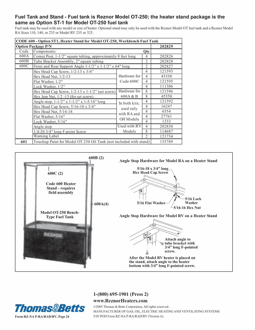
600A(4)
600C (2)
600B (2)Angle Stop Hardware for Model RA on a Heater Stand
Model OT-250 Bench-Type Fuel Tank
Code 600 HeaterStand - requiresfield assembly
Fuel Tank and Stand - Fuel tank is Reznor Model OT-250; the heater stand package is thesame as Option ST-1 for Model OT-250 fuel tankFuel tank may be used with any model or size of heater. Optional stand may only be used with the Reznor Model OT fuel tank and a Reznor Model
RA Sizes 110, 140, or 235 or Model RV 235 or 325.
5/16 LockWasher5/16 Flat Washer
5/16-18 x 3/4� longHex Head Cap Screw
5/16-16 Hex Nut
Attach angle totube bracket with3/4� long F-pointedscrew.
After the Model RV heater is placed onthe stand, attach angle to the heaterbottom with 3/4� long F-pointed screw.
Angle Stop Hardware for Model RV on a Heater Stand
Option Package P/N 202829
Code Components: Qty
600A 4 202826
600B 2 202828
600C 2 202827
Hex Head Cap Screw, 1/2-13 x 3/4” 4 121593
Hex Head Nut, 1/2-13 4 45550
Flat Washer, 1/2" 4 121595
Lock Washer, 1/2" 4 111306
Hex Head Cap Screw, 1/2-13 x 1-1/2” (set screw) 8 121596
Hex Jam Nut, 1/2 -13 (for set screw) 8 45550
Angle stop, 1-1/2” x 1-1/2” x 1-5/16" long 4 121592
Hex Head Cap Screw, 5/16-18 x 3/4” 4 16247
Hex Head Nut, 5/16-18 4 6554
Flat Washer, 5/16" 4 27761
Lock Washer, 5/16" 4 1333
Angle stop 4 202830
1/4-20 3/4" long F-point Screw 8 114687
2 121734
601 Touchup Paint for Model OT 250 Oil Tank (not included with stand) 135789
CODE 600 - Option ST1, Heater Stand for Model OT-250, Workbench Fuel Tank
Corner Post, 1-1/2” square tubing, approximately 8 feet long
Tube Bracket Assembly, 2" square tubing
Front and Rear Support Angle 1-1/2” x 1-1/2” x 64" long
Hardware for
Code 600C
In both kits;
used only
with RA and
OH Models
Used with RV
Models
Hardware for
600A & B
Warning Label