Embed Size (px)
Citation preview
Part number 550-142-054/0411 89
GV90+ gas-fired water boiler — Boiler Manual
Replacement parts
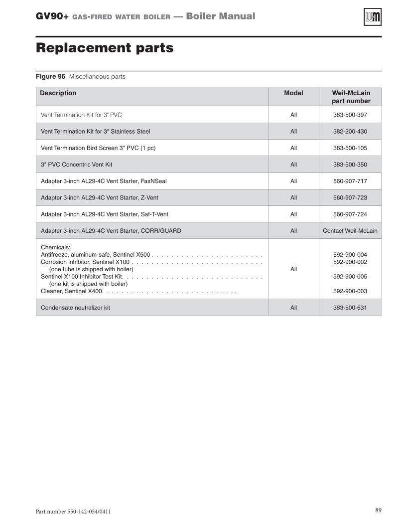
Figure 96 Miscellaneous parts
Description Model Weil-McLainpart number
Vent Termination Kit for 3" PVC All 383-500-397
Vent Termination Kit for 3" Stainless Steel All 382-200-430
Vent Termination Bird Screen 3" PVC (1 pc) All 383-500-105
3" PVC Concentric Vent Kit All 383-500-350
Adapter 3-inch AL29-4C Vent Starter, FasNSeal All 560-907-717
Adapter 3-inch AL29-4C Vent Starter, Z-Vent All 560-907-723
Adapter 3-inch AL29-4C Vent Starter, Saf-T-Vent All 560-907-724
Adapter 3-inch AL29-4C Vent Starter, CORR/GUARD All Contact Weil-McLain
Chemicals:Antifreeze, aluminum-safe, Sentinel X500 . . . . . . . . . . . . . . . . . . . . . . .Corrosion inhibitor, Sentinel X100 . . . . . . . . . . . . . . . . . . . . . . . . . . . (one tube is shipped with boiler)Sentinel X100 Inhibitor Test Kit. . . . . . . . . . . . . . . . . . . . . . . . . . . . . (one kit is shipped with boiler)Cleaner, Sentinel X400. . . . . . . . . . . . . . . . . . . . . . . . . . . .
All
592-900-004592-900-002
592-900-005
592-900-003
Condensate neutralizer kit All 383-500-631
Part number 550-142-054/0411
GV90+ gas-fired water boiler — Boiler Manual
90
Replacement parts (continued)
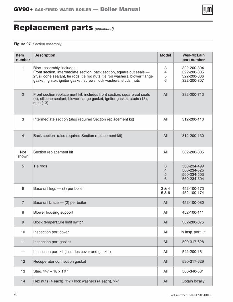
Figure 97 Section assembly
Itemnumber
Description Model Weil-McLainpart number
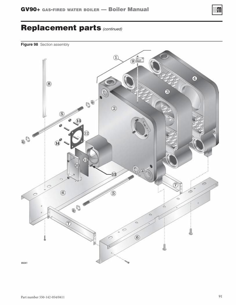
1 Block assembly, includes:Front section, intermediate section, back section, square cut seals — 2”, silicone sealant, tie rods, tie rod nuts, tie rod washers, blower flange gasket, igniter, igniter gasket, screws, lock washers, studs, nuts
3456
322-200-304322-200-305322-200-306322-200-307
2 Front section replacement kit, includes front section, square cut seals (4), silicone sealant, blower flange gasket, igniter gasket, studs (13), nuts (13)
All 382-200-713
3 Intermediate section (also required Section replacement kit) All 312-200-110
4 Back section (also required Section replacement kit) All 312-200-130
Not shown
Section replacement kit All 382-200-305
5 Tie rods 3456
560-234-499560-234-525560-234-503560-234-504
6 Base rail legs — (2) per boiler 3 & 45 & 6
452-100-173452-100-174
7 Base rail brace — (2) per boiler All 452-100-080
8 Blower housing support All 452-100-111
9 Block temperature limit switch All 382-200-375
10 Inspection port cover All In Insp. port kit
11 Inspection port gasket All 590-317-628
— Inspection port kit (includes cover and gasket) All 542-200-181
12 Recuperator connection gasket All 590-317-629
13 Stud, B\zn” – 18 x 1¼” All 560-340-581
14 Hex nuts (4 each), B\zn” / lock washers (4 each), B\zn” All Obtain locally
Part number 550-142-054/0411 91
GV90+ gas-fired water boiler — Boiler Manual
Figure 98 Section assembly
Replacement parts (continued)
Part number 550-142-054/0411
GV90+ gas-fired water boiler — Boiler Manual
92
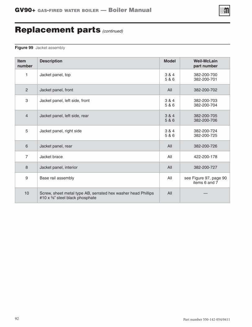
Figure 99 Jacket assembly
Itemnumber
Description Model Weil-McLainpart number
1 Jacket panel, top 3 & 45 & 6
382-200-700382-200-701
2 Jacket panel, front All 382-200-702
3 Jacket panel, left side, front 3 & 45 & 6
382-200-703382-200-704
4 Jacket panel, left side, rear 3 & 45 & 6
382-200-705382-200-706
5 Jacket panel, right side 3 & 45 & 6
382-200-724382-200-725
6 Jacket panel, rear All 382-200-726
7 Jacket brace All 422-200-178
8 Jacket panel, interior All 382-200-727
9 Base rail assembly All see Figure 97, page 90 items 6 and 7
10 Screw, sheet metal type AB, serrated hex washer head Phillips #10 x C\,” steel black phosphate
All —
Replacement parts (continued)
Part number 550-142-054/0411 93
GV90+ gas-fired water boiler — Boiler Manual
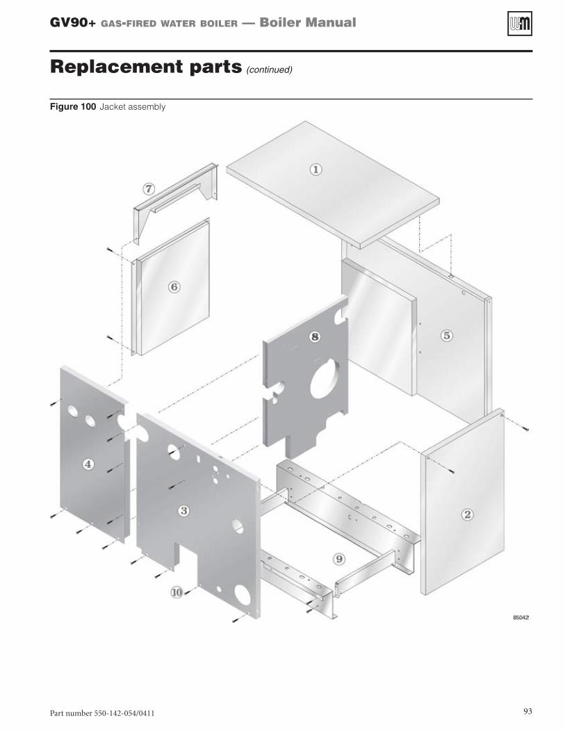
Figure 100 Jacket assembly
Replacement parts (continued)
Part number 550-142-054/0411
GV90+ gas-fired water boiler — Boiler Manual
94
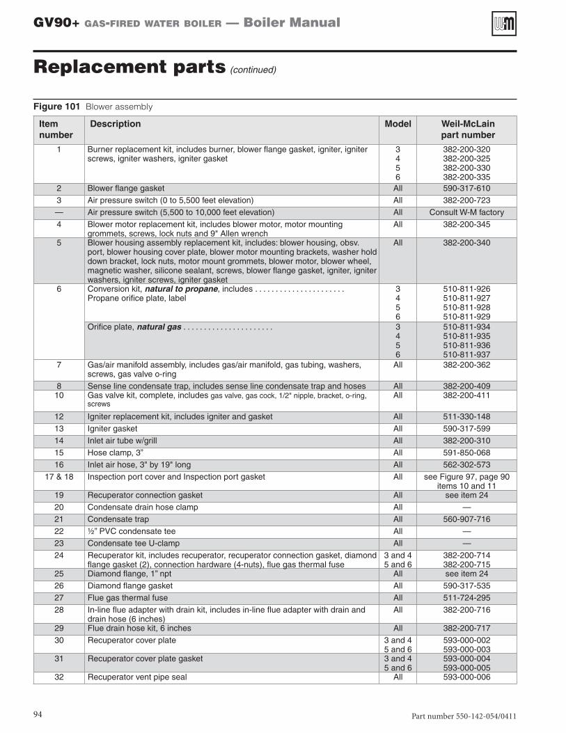
Figure 101 Blower assembly
Itemnumber
Description Model Weil-McLainpart number
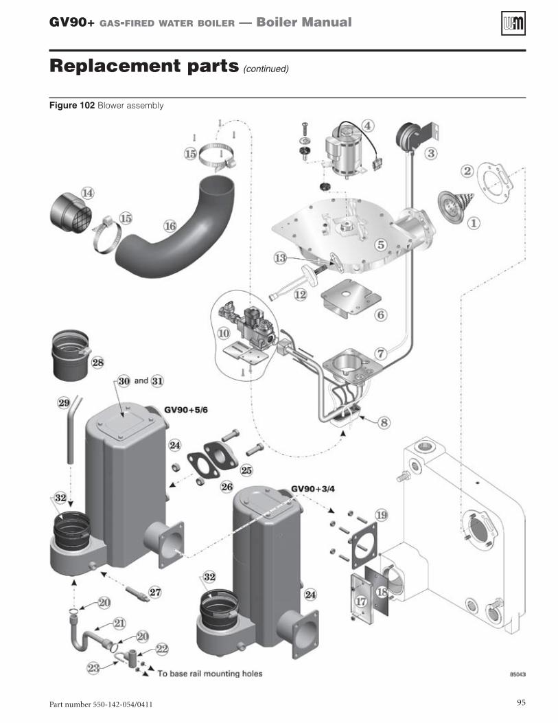
1 Burner replacement kit, includes burner, blower flange gasket, igniter, igniter screws, igniter washers, igniter gasket
3456
382-200-320382-200-325382-200-330382-200-335
2 Blower flange gasket All 590-317-6103 Air pressure switch (0 to 5,500 feet elevation) All 382-200-723— Air pressure switch (5,500 to 10,000 feet elevation) All Consult W-M factory4 Blower motor replacement kit, includes blower motor, motor mounting
grommets, screws, lock nuts and 9" Allen wrenchAll 382-200-345
5 Blower housing assembly replacement kit, includes: blower housing, obsv. port, blower housing cover plate, blower motor mounting brackets, washer hold down bracket, lock nuts, motor mount grommets, blower motor, blower wheel, magnetic washer, silicone sealant, screws, blower flange gasket, igniter, igniter washers, igniter screws, igniter gasket
All 382-200-340
6 Conversion kit, natural to propane, includes . . . . . . . . . . . . . . . . . . . . . .Propane orifice plate, label
3456
510-811-926510-811-927510-811-928510-811-929
Orifice plate, natural gas . . . . . . . . . . . . . . . . . . . . . . 3456
510-811-934510-811-935510-811-936510-811-937
7 Gas/air manifold assembly, includes gas/air manifold, gas tubing, washers, screws, gas valve o-ring
All 382-200-362
8 Sense line condensate trap, includes sense line condensate trap and hoses All 382-200-40910 Gas valve kit, complete, includes gas valve, gas cock, 1/2" nipple, bracket, o-ring,
screwsAll 382-200-411
12 Igniter replacement kit, includes igniter and gasket All 511-330-14813 Igniter gasket All 590-317-59914 Inlet air tube w/grill All 382-200-31015 Hose clamp, 3” All 591-850-06816 Inlet air hose, 3" by 19" long All 562-302-573
17 & 18 Inspection port cover and Inspection port gasket All see Figure 97, page 90 items 10 and 11
19 Recuperator connection gasket All see item 2420 Condensate drain hose clamp All —21 Condensate trap All 560-907-71622 ½” PVC condensate tee All —23 Condensate tee U-clamp All —24 Recuperator kit, includes recuperator, recuperator connection gasket, diamond
flange gasket (2), connection hardware (4-nuts), flue gas thermal fuse3 and 45 and 6
382-200-714382-200-715
25 Diamond flange, 1” npt All see item 2426 Diamond flange gasket All 590-317-53527 Flue gas thermal fuse All 511-724-29528 In-line flue adapter with drain kit, includes in-line flue adapter with drain and
drain hose (6 inches)All 382-200-716
29 Flue drain hose kit, 6 inches All 382-200-71730 Recuperator cover plate 3 and 4
5 and 6593-000-002593-000-003
31 Recuperator cover plate gasket 3 and 45 and 6
593-000-004593-000-005
32 Recuperator vent pipe seal All 593-000-006
Replacement parts (continued)
Part number 550-142-054/0411 95
GV90+ gas-fired water boiler — Boiler Manual
Figure 102 Blower assembly
Replacement parts (continued)
Part number 550-142-054/0411
GV90+ gas-fired water boiler — Boiler Manual
96
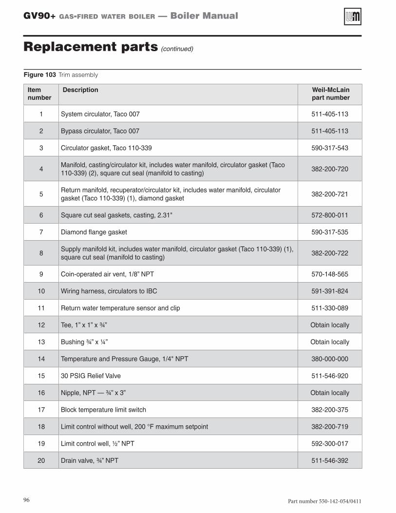
Figure 103 Trim assembly
Itemnumber
Description Weil-McLainpart number
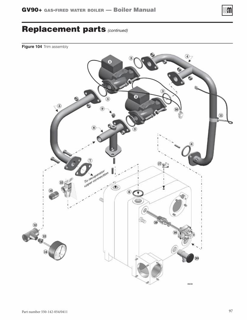
1 System circulator, Taco 007 511-405-113
2 Bypass circulator, Taco 007 511-405-113
3 Circulator gasket, Taco 110-339 590-317-543
4Manifold, casting/circulator kit, includes water manifold, circulator gasket (Taco 110-339) (2), square cut seal (manifold to casting)
382-200-720
5Return manifold, recuperator/circulator kit, includes water manifold, circulator gasket (Taco 110-339) (1), diamond gasket
382-200-721
6 Square cut seal gaskets, casting, 2.31" 572-800-011
7 Diamond flange gasket 590-317-535
8Supply manifold kit, includes water manifold, circulator gasket (Taco 110-339) (1), square cut seal (manifold to casting)
382-200-722
9 Coin-operated air vent, 1/8” NPT 570-148-565
10 Wiring harness, circulators to IBC 591-391-824
11 Return water temperature sensor and clip 511-330-089
12 Tee, 1” x 1” x ¾” Obtain locally
13 Bushing ¾” x ¼” Obtain locally
14 Temperature and Pressure Gauge, 1/4" NPT 380-000-000
15 30 PSIG Relief Valve 511-546-920
16 Nipple, NPT — ¾” x 3” Obtain locally
17 Block temperature limit switch 382-200-375
18 Limit control without well, 200 °F maximum setpoint 382-200-719
19 Limit control well, ½” NPT 592-300-017
20 Drain valve, ¾” NPT 511-546-392
Replacement parts (continued)
Part number 550-142-054/0411 97
GV90+ gas-fired water boiler — Boiler Manual
Figure 104 Trim assembly
Replacement parts (continued)
Part number 550-142-054/0411
GV90+ gas-fired water boiler — Boiler Manual
98
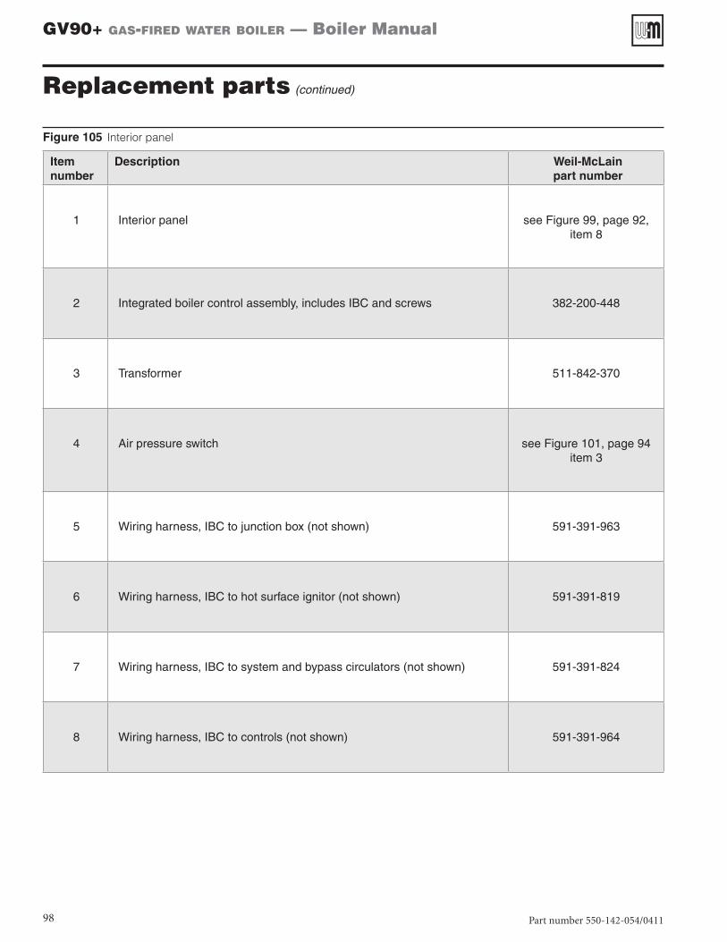
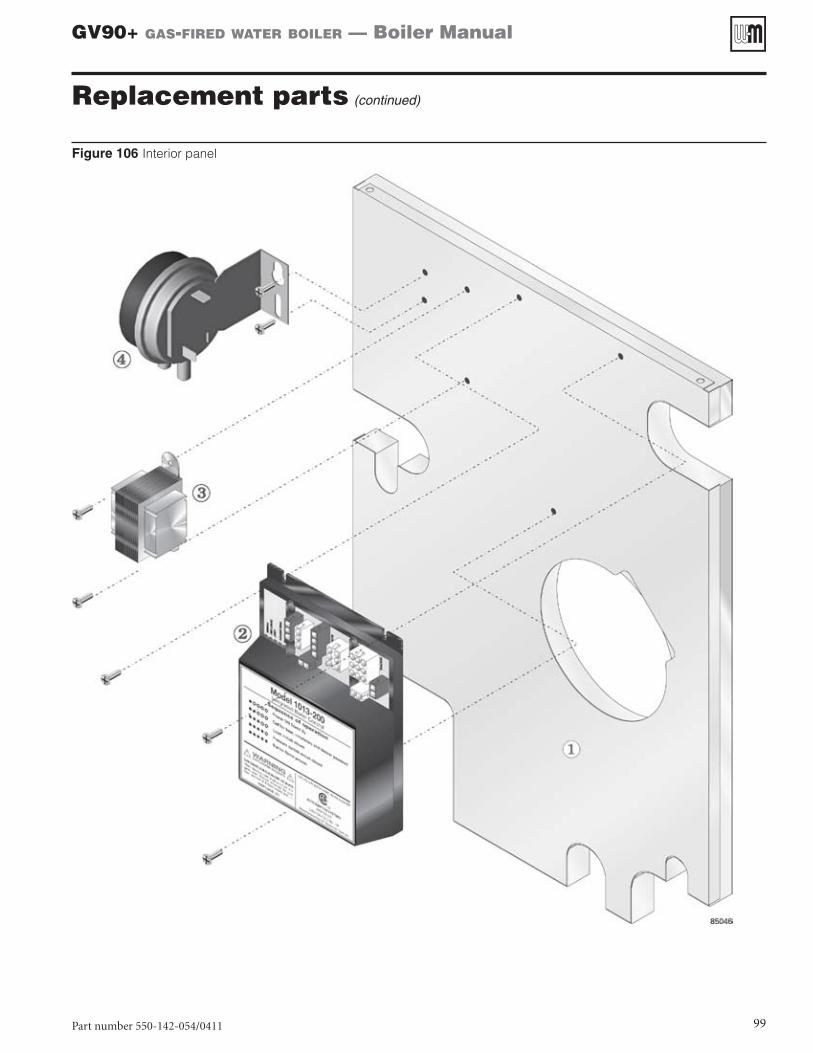
Figure 105 Interior panel
Itemnumber
Description Weil-McLainpart number
1 Interior panel see Figure 99, page 92, item 8
2 Integrated boiler control assembly, includes IBC and screws 382-200-448
3 Transformer 511-842-370
4 Air pressure switch see Figure 101, page 94 item 3
5 Wiring harness, IBC to junction box (not shown) 591-391-963
6 Wiring harness, IBC to hot surface ignitor (not shown) 591-391-819
7 Wiring harness, IBC to system and bypass circulators (not shown) 591-391-824
8 Wiring harness, IBC to controls (not shown) 591-391-964
Replacement parts (continued)
Part number 550-142-054/0411 99
GV90+ gas-fired water boiler — Boiler Manual
Figure 106 Interior panel
Replacement parts (continued)
Part number 550-142-054/0411
GV90+ gas-fired water boiler — Boiler Manual
100
Dimensions and ratings
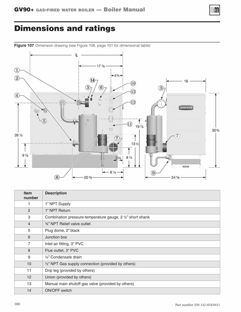
Figure 107 Dimension drawing (see Figure 108, page 101 for dimensional table)
Itemnumber
Description
1 1” NPT Supply
2 1” NPT Return
3 Combination pressure-temperature gauge, 2 ½” short shank
4 ¾” NPT Relief valve outlet
5 Plug dome, 2” black
6 Junction box
7 Inlet air fitting, 3" PVC
8 Flue outlet, 3" PVC
9 ½” Condensate drain
10 ½” NPT Gas supply connection (provided by others)
11 Drip leg (provided by others)
12 Union (provided by others)
13 Manual main shutoff gas valve (provided by others)
14 ON/OFF switch
Part number 550-142-054/0411 101
GV90+ gas-fired water boiler — Boiler Manual
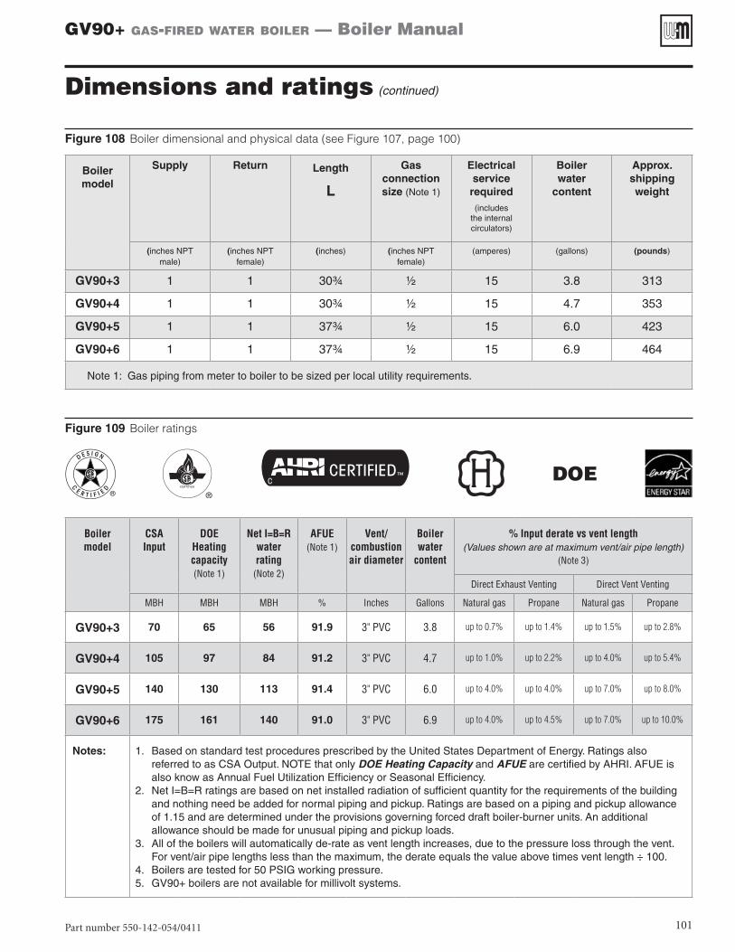
Figure 108 Boiler dimensional and physical data (see Figure 107, page 100)
Boiler model
Supply
Return Length
L
Gas connection size (Note 1)
Electrical service required
(includes the internal circulators)
Boiler water
content
Approx. shipping weight
(inches NPT male)
(inches NPT female)
(inches) (inches NPT female)
(amperes) (gallons) (pounds)
GV90+3 1 1 30¾ ½ 15 3.8 313
GV90+4 1 1 30¾ ½ 15 4.7 353
GV90+5 1 1 37¾ ½ 15 6.0 423
GV90+6 1 1 37¾ ½ 15 6.9 464
Note 1: Gas piping from meter to boiler to be sized per local utility requirements.
Figure 109 Boiler ratings
DOE
Boiler model
CSA Input
DOE Heating capacity (Note 1)
Net I=B=R water rating
(Note 2)
AFUE (Note 1)
Vent/combustion air diameter
Boiler water
content
% Input derate vs vent length (Values shown are at maximum vent/air pipe length)
(Note 3)
Direct Exhaust Venting Direct Vent Venting
MBH MBH MBH % Inches Gallons Natural gas Propane Natural gas Propane
GV90+3 70 65 56 91.9 3" PVC 3.8 up to 0.7% up to 1.4% up to 1.5% up to 2.8%
GV90+4 105 97 84 91.2 3" PVC 4.7 up to 1.0% up to 2.2% up to 4.0% up to 5.4%
GV90+5 140 130 113 91.4 3" PVC 6.0 up to 4.0% up to 4.0% up to 7.0% up to 8.0%
GV90+6 175 161 140 91.0 3" PVC 6.9 up to 4.0% up to 4.5% up to 7.0% up to 10.0%
Notes: 1. Based on standard test procedures prescribed by the United States Department of Energy. Ratings also referred to as CSA Output. NOTE that only DOE Heating Capacity and AFUE are certified by AHRI. AFUE is also know as Annual Fuel Utilization Efficiency or Seasonal Efficiency.
2. Net I=B=R ratings are based on net installed radiation of sufficient quantity for the requirements of the building and nothing need be added for normal piping and pickup. Ratings are based on a piping and pickup allowance of 1.15 and are determined under the provisions governing forced draft boiler-burner units. An additional allowance should be made for unusual piping and pickup loads.
3. All of the boilers will automatically de-rate as vent length increases, due to the pressure loss through the vent. For vent/air pipe lengths less than the maximum, the derate equals the value above times vent length ÷ 100.
4. Boilers are tested for 50 PSIG working pressure. 5. GV90+ boilers are not available for millivolt systems.
Dimensions and ratings (continued)
Part number 550-142-054/0411
GV90+ gas-fired water boiler — Boiler Manual
102
Dimensions and ratings (continued)
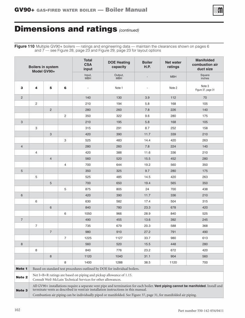
Figure 110 Multiple GV90+ boilers — ratings and engineering data — maintain the clearances shown on pages 6 and 7 — see Figure 28, page 23 and Figure 29, page 23 for layout options
Boilers in systemModel GV90+
Total CSA input
DOE Heating capacity
Boiler H.P.
Net water ratings
Manifolded combustion air
duct size
Input, MBH
Output, MBH - MBH Square
inches
3 4 5 6 - Note 1 - Note 2 Note 3Figure 37, page 31
2 140 130 3.9 112 70
2 210 194 5.8 168 105
2 280 260 7.8 226 140
2 350 322 9.6 280 175
3 210 195 5.8 168 105
3 315 291 8.7 252 158
3 420 390 11.7 339 210
3 525 483 14.4 420 263
4 280 260 7.8 224 140
4 420 388 11.6 336 210
4 560 520 15.5 452 280
4 700 644 19.2 560 350
5 350 325 9.7 280 175
5 525 485 14.5 420 263
5 700 650 19.4 565 350
5 875 805 24 700 438
6 420 390 11.7 336 210
6 630 582 17.4 504 315
6 840 780 23.3 678 420
6 1050 966 28.9 840 525
7 490 455 13.6 392 245
7 735 679 20.3 588 368
7 980 910 27.2 791 490
7 1225 1127 33.7 980 613
8 560 520 15.5 448 280
8 840 776 23.2 672 420
8 1120 1040 31.1 904 560
8 1400 1288 38.5 1120 700
Note 1 Based on standard test procedures outlined by DOE for individual boilers.
Note 2Net I=B=R ratings are based on piping and pickup allowance of 1.15.Consult Weil-McLain Technical Services for other allowances.
Note 3All GV90+ installations require a separate vent pipe and termination for each boiler. Vent piping cannot be manifolded. Install and terminate vents as described in vent/air installation instructions in this manual.
Combustion air piping can be individually piped or manifolded. See Figure 37, page 31, for manifolded air piping.
Part number 550-142-054/0411 103
GV90+ gas-fired water boiler — Boiler Manual
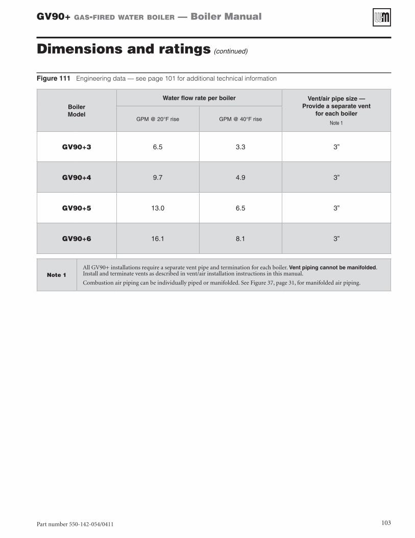
Figure 111 Engineering data — see page 101 for additional technical information
Boiler Model
Water flow rate per boiler Vent/air pipe size — Provide a separate vent
for each boiler
Note 1GPM @ 20°F rise GPM @ 40°F rise
GV90+3 6.5 3.3 3”
GV90+4 9.7 4.9 3”
GV90+5 13.0 6.5 3”
GV90+6 16.1 8.1 3”
Note 1All GV90+ installations require a separate vent pipe and termination for each boiler. Vent piping cannot be manifolded. Install and terminate vents as described in vent/air installation instructions in this manual.
Combustion air piping can be individually piped or manifolded. See Figure 37, page 31, for manifolded air piping.
Dimensions and ratings (continued)

Part number 550-142-054/0411
GV90+ gas-fired water boiler — Boiler Manual
104
NOTES
Part number 550-142-054/0411 105
GV90+ gas-fired water boiler — Boiler Manual
NOTES (continued)
Part number 550-142-054/0411
GV90+ gas-fired water boiler — Boiler Manual
106
NOTES
Part number 550-142-054/0411 107
GV90+ gas-fired water boiler — Boiler Manual
Handling ceramic fiber and fiberglass materials
HANDLING CERAMIC FIBER MATERIALS
Ceramic fibers can be converted to cristobalite in very high temperature applications. The International Agency for Research on Cancer (IARC) has concluded, “Crystalline silica inhaled in the form of quartz or cristobalite from occupational sources is carcinogenic to humans (Group 1).”:
❏❏ Avoid breathing dust and contact with skin and eyes.
• Use NIOSH certified dust respirator (N95). This type of respirator is based on the OSHA requirements for cristobalite at the time this document was written. Other types of respirators may be needed depending on the job site conditions. Current NIOSH recom-mendations can be found on the NIOSH web site at http://www.cdc.gov/niosh/homepage.html. NIOSH approved respirators, manufacturers, and phone numbers are also listed on this web site.
• Wear long-sleeved, loose fitting clothing, gloves, and eye protection.
❏❏ Apply enough water to the combustion chamber lining or base insulation to prevent airborne dust.
❏❏ Remove combustion chamber lining or base insula-tion from the boiler and place it in a plastic bag for disposal.
❏❏ Wash potentially contaminated clothes separately from other clothing. Rinse clothes washer thoroughly.
NIOSH stated First Aid
❏❏ Eye: Irrigate immediately
❏❏ Breathing: Fresh air
REMOVAL OR INSTALLATION OF FIBERGLASS WOOL
This product contains fiberglass jacket insula-tion and ceramic fiber materials in combus-tion chamber lining or base panels in gas fired products. Airborne fibers from these materials have been listed by the State of California as a possible cause of cancer through inhalation.
❏❏ Avoid breathing dust and contact with skin and eyes.
• Use NIOSH certified dust respirator (N95). This type of respirator is based on the OSHA requirements for fiberglass wool at the time this document was written. Other types of respirators may be needed depending on the job site conditions. Current NIOSH recom-mendations can be found on the NIOSH web site at http://www.cdc.gov/niosh/homepage.html. NIOSH approved respirators, manufacturers, and phone numbers are also listed on this web site.
• Wear long-sleeved, loose fitting clothing, gloves, and eye protection.
❏❏ Operations such as sawing, blowing, tear out, and spray-ing may generate airborne fiber concentration requiring additional protection.
❏❏ Wash potentially contaminated clothes separately from other clothing. Rinse clothes washer thoroughly.
NIOSH stated First Aid
❏❏ Eye: Irrigate immediately
❏❏ Breathing: Fresh air
GV90+ gas-fired water boiler — Boiler Manual
Installation and service certificate
Boiler model __________________ Series __________ CP number ___________ Date installed _______________
Measured Btuh input ____________
Installer ________________________ ________________________________ ______________________________ (company) (address) (phone)
_______________________________ (installer’s signature)
Installation instructions have been followed.
Check-out sequence has been performed.
Above information is certified to be correct.
Information received and left with owner/maintenance person.