Embed Size (px)
Citation preview

Replacing a controller module in a 2240 system
To replace a controller module, you must remove the faulty controller module from the system and move the replaceablecomponents from the old controller module to the new controller module. You then install the new controller module in thesystem chassis.
Before you begin
Your system must conform to the following:
• All disk shelves must be working properly.• If your system is in an HA configuration, the partner node must be able to take over the target node.
About this task
• You can use this procedure with all versions of Data ONTAP supported by your system.• This procedure refers to HA pairs, which in releases prior to Data ONTAP 8.0 were called active/active configurations.• You must be replacing a controller module with a controller module of the same model type; you cannot upgrade your
system by just replacing the controller module.• You cannot change any disks or disk shelves as part of this procedure.
Steps
1. Saving the Fibre Channel configuration for HA pairs in SAN configurations on page 1
2. Shutting down the node on page 2
3. Removing the controller module and moving the components on page 3
4. Installing the new controller module and booting the system on page 11
5. Running diagnostics on the controller module on page 12
6. Setting the time after replacing the controller module on page 14
7. Installing the firmware after replacing the controller module on page 15
8. Restoring the Fibre Channel configuration for HA pairs in SAN configurations on page 15
9. Reassigning disks on page 16
10. Performing a final takeover and giveback from the target node on page 21
11. Restoring Storage Encryption functionality after controller module replacement on page 21
12. Completing the replacement process on page 22
Saving the Fibre Channel configuration for HA pairs in SAN configurationsIf you have a SAN configuration and the system is in an HA pair, you must save the onboard FC port configuration informationbefore replacing the controller module, so that you can reenter it on the new controller module.
Steps
1. Enter the following command from the target node to save the onboard FC port configuration information for the node (thesystem on which you are replacing the controller module):
If your system is configured in... Then issue this command...
7-Mode fcadmin config
1215-06447_A0 Copyright © 2011 NetApp, Inc. All rights reserved.

If your system is configured in... Then issue this command...
Cluster-Mode run local fcadmin config
2. Copy and save the screen display to a safe location for later reuse.
Shutting down the nodeYou shut down a node using different procedures, depending on whether it is part of an HA pair or a stand-alone system.
Shutting down a node in an HA pairTo shut down the node, you must determine the status of the node and, if necessary, take over the node so that the partnercontinues to serve data from the node's storage.
Steps
1. Check the status of the target node (the node you want to perform maintenance on) by entering the following command atthe system console of either node:
If your system is configured in... Then issue this command...
7-Mode cf status
Cluster-Mode storage failover show
2. Take one of the following actions, depending on the result of the cf status or storage failover show command:
If... Then...
Neither node is in takeover mode Go to the next step in this procedure.
The partner node took over thetarget node
The target node is in a state where you can begin removing it from the system chassis.
The target node took over thepartner node
a. Correct the problem that caused the takeover.
b. Run the cf giveback command (if in a 7-Mode system) or storage failovergiveback -fromnode nodename command (if in a Cluster-Mode system) from thetarget node console.
c. Go back to the beginning of this procedure.
3. Take over the target node by entering one of the following commands from the partner node’s console:
If your system is configured in... Then issue this command...
7-Mode cf takeover
Cluster-Mode storage failover takeover -bynode node
Shutting down the node in a stand-alone systemFor a node that is in a stand-alone configuration, you must perform a clean shutdown (ensuring that all data has been written todisk) and disconnect the power supplies.
Steps
1. Enter one of the following commands from the system console:
2 Replacing a controller module in a 2240 system

If your system is configured in... Then issue this command...
7-Mode halt
Cluster-Mode halt local
After you issue the command, wait until the system stops at the LOADER prompt.
Attention: You must perform a clean system shutdown before replacing system components to avoid losing unwrittendata in the nonvolatile memory (NVMEM). The NVMEM LED is marked with a battery symbol and is located on thecontroller module to the left of the label showing the MAC address. If the NVMEM LED is flashing, there is content inthe NVMEM that has not been saved to disk. You need to reboot the controller module and proceed from the beginning ofthis procedure. If repeated attempts to cleanly shut down the controller module fail, be aware that you might lose any datathat was not saved to disk.
2. If you are not already grounded, properly ground yourself.
3. Turn off the power supplies and unplug both power cords from the power source:
If your system uses... Then...
AC power supplies Unplug the power cords from the power source, and then remove the power cords.
DC power supplies Remove the power at the DC source, and remove the DC wires, if necessary.
Removing the controller module and moving the componentsYou must remove the old controller module from the chassis and move all field-replaceable components from the old controllermodule to the new controller module.
About this task
To reduce the possibility of damage to the replaceable components, you should minimize handling by installing the componentsinto the new controller module as soon as you remove them from the old controller module.
Note: You must also move the SFP modules from the old controller module to the new one.
Removing the controller module from the systemTo replace the controller module, you must first remove the old controller module from the system.
Steps
1. If you are not already grounded, properly ground yourself.
2. Unplug the system cables from the controller module, as needed, and keep track of where the cables were connected.
Leave the cables in the cable management arm, so that when you reinstall the cable management arm, the cables areorganized.
3. Remove the cable management arms for the left and right sides of the controller module and set them aside.
3

4. If you left the SFP modules in the system after removing the cables, move them to the new controller module.
5. Squeeze the latch on the cam handle until it releases, open the cam handle fully to release the controller module from themidplane, and then, using two hands, pull the controller module out of the chassis.
6. Turn the controller module over and open it by sliding the blue tabs to release the cover, and then swing the cover up andopen.
4 Replacing a controller module in a 2240 system
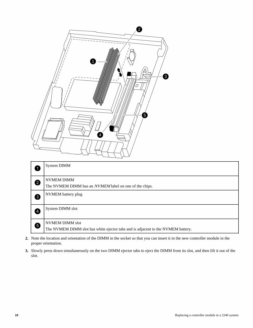
Moving the mezzanine cardTo move the mezzanine card from the old controller module to the new controller module, you must perform a specificsequence of steps.
Steps
1. Release the lever that holds the mezzanine card in place.
5

2
4
3
1
1Mezzanine card
2Mezzanine card connector
3Motherboard socket for mezzanine card connector
4Lever (when closed, engages and locks the mezzanine card connector in the socket)
2. Swing the card up and lift it out of the controller module.
6 Replacing a controller module in a 2240 system

3. Align the mezzanine card I/O panel in the slot in the front of the new controller module, and swing the card down to seat theconnector into the socket on the controller module.
4. Close and push down on the blue lever to engage the mezzanine card connector and to secure the mezzanine card.
Moving the boot deviceTo move the boot device from the old controller module to the new controller module, you must perform a specific sequence ofsteps.
Steps
1. Locate the boot device using the following illustration or the FRU map on the controller module.
7

1Boot device
2Boot device socket
2. Open the boot device cover and gently lift the boot device out of the housing.
While lifting the boot device out of the housing, make sure that you hold the boot device by the sides adjacent to the notcheson the housing.
3. Open the boot device cover on the new controller module.
4. Align the boot device with the boot device socket or connector, and then firmly push the boot device into the socket orconnector.
5. Check the boot device to make sure that it is seated squarely and completely in the socket or connector.
If necessary, remove the boot device and reseat it into the socket.
6. Close the boot device cover.
Moving the NVMEM batteryTo move the NVMEM battery from the old controller module to the new controller module, you must perform a specificsequence of steps.
Steps
1. Locate the battery, press the clip on the face of the battery plug to release the lock clip from the plug socket, and unplug thebattery cable from the socket.
8 Replacing a controller module in a 2240 system

1NVMEM battery
2. Grasp the battery and press the tab marked PUSH, and then lift the battery out of the holder and controller module.
3. In the new controller module, seat the battery in the holder and plug the battery cable into the socket.
The plug should lock down onto the socket on the controller module.
Moving the DIMMs to the new controller moduleYou must remove the DIMMs from the old controller module, being careful to note their locations so that you can reinstall themin the correct sockets in the new controller module.
Steps
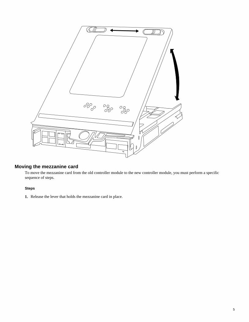
1. Locate the DIMMs.
Note: Each system memory DIMM has an LED located on the board next to each DIMM slot. The LED is illuminated ifthe DIMM needs to be replaced.
9
1
5
2
4
3
1System DIMM
2NVMEM DIMM
The NVMEM DIMM has an NVMEM label on one of the chips.
3NVMEM battery plug
4System DIMM slot
5NVMEM DIMM slot
The NVMEM DIMM slot has white ejector tabs and is adjacent to the NVMEM battery.
2. Note the location and orientation of the DIMM in the socket so that you can insert it in the new controller module in theproper orientation.
3. Slowly press down simultaneously on the two DIMM ejector tabs to eject the DIMM from its slot, and then lift it out of theslot.
10 Replacing a controller module in a 2240 system

Attention: Carefully hold the DIMM by the edges to avoid pressure on the components on the DIMM circuit board.
4. Locate the corresponding slot for the DIMM in the new controller module, align the DIMM over the slot, and insert theDIMM straight into the slot.
The notch among the pins on the DIMM should align with the tab in the socket. The DIMM fits tightly in the slot but shouldgo in easily. If not, realign the DIMM with the slot and reinsert it.
Visually inspect the DIMM to verify that it is evenly aligned and fully inserted into the slot. The edge connector on theDIMM must make complete contact with the slot.
Important: Make sure that you install the NVMEM DIMM only in the NVMEM DIMM slot.
5. Push carefully, but firmly, on the top edge of the DIMM until the latches snap into place over the notches at the ends of theDIMM.
6. Repeat these steps to move additional DIMMs as needed.
Installing the new controller module and booting the systemAfter you install the components from the old controller module into the new controller module, you must install the newcontroller module into the system chassis and boot the operating system.
About this task
Attention: For HA pairs, the sequence in which you reinstall the controller module is especially important because it attemptsto reboot as soon as you completely seat it in the chassis.
Steps
1. Close and latch the controller module cover, if necessary.
2. Reinstall the cable management arms and recable the controller module, as needed.
When recabling, remember to reinstall the media converters (SFPs) if you are using fiber cables.
3. Install the new controller module and boot it:
11

If your system isin...
Then perform these steps...
An HA pair a. Be prepared to interrupt the boot process.The controller module begins to boot as soon as it is fullly seated in the chassis.
b. With the cam handle in the open position, insert the new controller module into the chassis, firmly pushinguntil the controller module meets the midplane, and then close the cam handle so that the latch clicks into thelocked position and the controller module is fully seated.
Attention: Do not use excessive force when sliding the controller module into the chassis; you mightdamage the connectors.
c. As the system begins to boot, press Ctrl-c to interrupt the boot process.
A stand-aloneconfiguration
a. With the cam handle in the open position, insert the new controller module into the chassis, firmly pushinguntil the controller module meets the midplane, and then close the cam handle so that the latch clicks into thelocked position and the controller module is fully seated.
Attention: Do not use excessive force when sliding the controller module into the chassis; you mightdamage the connectors.
b. Reconnect the power cables to the power supplies and to the power sources, turn on the power to start the bootprocess, and then press Ctrl-c.
Running diagnostics on the controller moduleYou should run diagnostics on the new controller module to verify its operation.
Steps
1. Complete the applicable step, depending on where the node halted during the boot process.
If the node halted at the... Then...
Loader prompt Continue with the procedure.
Boot menu a. Select the Maintenance mode option from the displayed menu.
b. Enter the following command at the prompt:
halt
After you issue the command, wait until the system stops at the LOADER prompt.
c. Continue with the procedure.
2. Enter the following command at the Loader prompt:
boot_diags
Note: You must run this command from the Loader prompt for system-level diagnostics to function properly. Theboot_diags command starts special drivers designed specifically for system-level diagnostics.
The Maintenance mode prompt (*>) appears.
3. Enter the following command at the Maintenance mode prompt:
sldiag
For details about the sldiag command, see the sldiag man page.
4. Clear the status logs by entering the following command:
12 Replacing a controller module in a 2240 system
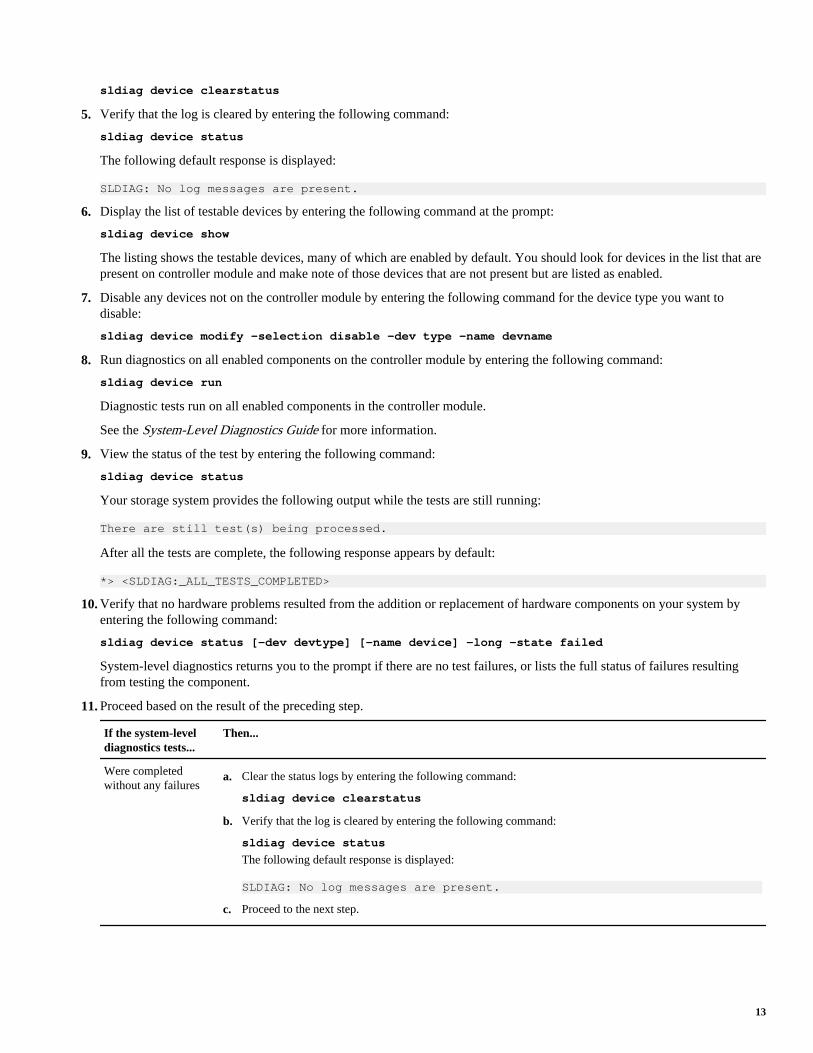
sldiag device clearstatus
5. Verify that the log is cleared by entering the following command:
sldiag device status
The following default response is displayed:
SLDIAG: No log messages are present.
6. Display the list of testable devices by entering the following command at the prompt:
sldiag device show
The listing shows the testable devices, many of which are enabled by default. You should look for devices in the list that arepresent on controller module and make note of those devices that are not present but are listed as enabled.
7. Disable any devices not on the controller module by entering the following command for the device type you want todisable:
sldiag device modify -selection disable -dev type -name devname
8. Run diagnostics on all enabled components on the controller module by entering the following command:
sldiag device run
Diagnostic tests run on all enabled components in the controller module.
See the System-Level Diagnostics Guide for more information.
9. View the status of the test by entering the following command:
sldiag device status
Your storage system provides the following output while the tests are still running:
There are still test(s) being processed.
After all the tests are complete, the following response appears by default:
*> <SLDIAG:_ALL_TESTS_COMPLETED>
10. Verify that no hardware problems resulted from the addition or replacement of hardware components on your system byentering the following command:
sldiag device status [-dev devtype] [-name device] -long -state failed
System-level diagnostics returns you to the prompt if there are no test failures, or lists the full status of failures resultingfrom testing the component.
11. Proceed based on the result of the preceding step.
If the system-leveldiagnostics tests...
Then...
Were completedwithout any failures
a. Clear the status logs by entering the following command:
sldiag device clearstatus
b. Verify that the log is cleared by entering the following command:
sldiag device status
The following default response is displayed:
SLDIAG: No log messages are present.
c. Proceed to the next step.
13

If the system-leveldiagnostics tests...
Then...
Resulted in some testfailures
Determine the cause of the problem.
a. Exit Maintenance mode by entering the following command:
halt
b. Perform a clean shutdown and disconnect the power supplies.
Important: If your system is in an HA configuration, do not turn off power to the system.
c. Verify that you have observed all the considerations identified for running system-level diagnostics, thatcables are securely connected, and that hardware components are properly installed in the storage system.
d. Reconnect the power supplies and power on the storage system, as needed.
e. Rerun the system-level diagnostics tests.
12. Exit Maintenance mode by entering the following command:
halt
Related information
NetApp Hardware SLDiagnostics Guide: now.netapp.com/NOW/knowledge/docs/hardware/NetApp/diag/sldiag.pdf
Setting the time after replacing the controller moduleIf your system is in an HA pair, you must set the time on both controller modules to prevent possible outages on clients due totime differences.
About this task
It is important that you apply the commands in these steps on the correct systems:
• The target node is the node on which you are performing maintenance.• The partner node is the HA partner of the target node.
Steps
1. If you have not already done so, reboot the target node and press Ctrl-c when prompted to halt the boot process and displaythe Loader prompt.
2. Determine the system time by using the date command on the partner node (if the system is in an HA pair) or anotherreliable time source.
3. Enter the following command to set the date on the target node:
set date mm/dd/yyyy
4. Enter the following command to set the time on the target node:
set time hh:mm:ss
14 Replacing a controller module in a 2240 system

Installing the firmware after replacing the controller moduleAfter replacing the controller module you must install the latest firmware on the new controller module.
Step
1. Log in to the NetApp Support Site, select the most current version of firmware for your system from those listed at now.netapp.com/NOW/download/tools/serviceimage/, and then follow the instructions for downloading and installing thenew firmware.
Note: You can take this opportunity to also download and install the SP firmware and BIOS on the partner node, ifneeded.
Note: Installing a new controller module changes the World Wide Port Name (WWPN) and World Wide Node Name(WWNN) values associated with each onboard FC port. If your configuration uses switched-based zoning, you mustadjust the switch zoning to reflect the new WWPN and WWNN values. If your configuration includes a V-Series system,you must also adjust the WWPN values in the host or volume groups associated with arrays on the storage subsystem.
Restoring the Fibre Channel configuration for HA pairs in SANconfigurations
Because the onboard FC ports are not preconfigured, you must restore the FC port configurations in your HA pair before youbring the node back into service; otherwise, you might experience a disruption in service.
Before you begin
You must have the values of the FC port settings that you saved earlier.
Steps
1. Verify the values of the FC configuration on the target node by entering the following command from the partner nodeconsole:
If your system is operating in... Then issue this command...
7-Mode or Data ONTAP versions previous to 8.0 partner fcadmin config
Cluster-Mode run partner fcadmin config
2. Compare the default FC variable settings with the list you saved earlier.
If the FC variablesare...
Then...
The same as yourecorded earlier
Proceed to the next step in this procedure.
15

If the FC variablesare...
Then...
Different than yourecorded earlier
a. If you have not already done so, reboot the target node to Maintenance mode by pressing Ctrl-c whenprompted.
b. Answer y when prompted by the system.
c. Enter one of the following commands, depending on what you need to do:
• To program target ports:
fcadmin config -t target adapter_name
• To program initiator ports:
fcadmin config -t initiator adapter_name
• To unconfigure ports:
fcadmin config -t unconfigure adapter_name
d. Halt the target node by entering the following command:
halt
e. Verify the values of the variables by entering the following command:
printenv
Reassigning disksBecause the new controller module has a new system ID, you must reassign the disks attached to the target node (the node onwhich the controller module has been replaced) so that they point to the new system ID.
About this task
• You can use this procedure with all versions of Data ONTAP supported by your system.In this procedure, a 7-Mode system refers to a system running Data ONTAP 8.x 7-Mode.
• It is important that you apply the commands in these steps on the correct system:
• The target node is the node on which you are performing maintenance.• The partner node is the HA partner of the target node.
Reassigning disks on a 7-Mode systemYou must reassign disks before you boot the software. Some of the steps are different depending on whether the system is stand-alone or in an HA pair.
About this task
• It is important that you apply the commands in these steps on the correct systems:
• The target node is the node on which you are performing maintenance.• The partner node is the HA partner of the target node.
• You cannot reassign more than 500 disks from one controller to another by using the disk reassign command.If you try to do so, the system reports an error. If you want to reassign more than 500 disks, contact technical support.
Steps
1. If you have not already done so, reboot the target node, interrupt the boot process by entering Ctrl-c, and then select theoption to boot to Maintenance mode from the displayed menu.
16 Replacing a controller module in a 2240 system

Press y when prompted to override the system ID due to a system ID mismatch.
2. View the new system IDs by entering the following command:
disk show -v
Note: Make note of the new system ID, which is displayed in the Local System ID field. The following example containsthe following information:
• system-2 is the target node, which is undergoing maintenance.• system-1 is the partner node.• The new system ID is 118065481.• The old system ID is 118073209, which is still assigned to the disks owned by system-2.
Example
*> disk show -vLocal System ID: 118065481 DISK OWNER POOL SERIAL NUMBER HOME-------- ------------- ----- ------------- -------------0b.29 system-1 (118065578) Pool0 J8XJE9LC system-1 (118065578)0a.27 system-2 (118073209) Pool0 J8Y478RC system-2 (118073209)...
3. Reassign disk ownership based on your system's configuration:
If the controllermodule is...
Then perform these steps on the applicable node...
In an HA pair a. Halt the target node by entering the following command on the target node:
halt
b. Confirm that the target node has been taken over by entering the following command on the partner node:
cf status
If the target node has not been taken over, you should use the cf takeover command on the partner node totake it over.
c. On the partner node, enter the following command to enter advanced privilege mode:
priv set advanced
d. On the partner node, reassign disk ownership (for FAS systems) or LUN ownership (for V-Series systems), usingthe system ID information obtained from the disk show -v command:
disk reassign -s old system ID -d new system ID
Continuing the preceding example:
• The old system ID is 118073209.
• The new system ID is 118065481.
Stand-alone Reassign disk ownership by entering the following command at the Maintenance mode prompt of the target node:
disk reassign -s old system ID -d new system ID
Continuing the preceding example:
• The old system ID is 118073209.
• The new system ID is 118065481.
Note: Do not issue any commands relating to aggregates until the entire procedure is completed.
4. Verify that the disks (or V-Series LUNs) were assigned correctly by entering the following command:
17

disk show -v
Note: If your system is in an HA pair, you must run this command on the partner node.
Make sure that the disks belonging to the target node show the new system ID for the target node. In the following example,the disks owned by system-2 now show the new system ID, 118065481:
Example
system-1> disk show -v DISK OWNER POOL SERIAL NUMBER HOME------- ------------- ----- ------------- -------------0b.17 system-2 (118065481) Pool0 J8Y0TDZC system-2 (118065481)0a.17 system-1 (118065578) Pool0 J8Y09DXC system-1 (118065578)...
5. Exit Maintenance mode by entering the following command on the target node:
halt
6. After the target node displays the boot prompt, enter the following command to boot the operating system:
boot_ontap
For a system in an HA pair, this puts the node in Waiting for Giveback state.
7. Proceed depending on whether the system is in an HA pair:
If the controller module is... Then...
In an HA pair a. On the partner node, enter the following command to return to standard privilege mode:
priv set admin
b. On the partner node, return storage to the target node by entering the following command:
cf giveback
c. Proceed to the next task for your configuration type..
Stand-alone Proceed to the next task for your configuration type.
Reassigning disks on a Cluster-Mode systemYou must assign the NVRAM system ID of the new to the disks in the system.
About this task
• It is important that you apply the commands in these steps on the correct systems:
• The target node is the node on which you are performing maintenance.• The partner node is the HA partner of the target node.
• The target system must have been taken over by its partner.If the target node has not been taken over, you should use the cf takeover command on the partner node to take it over.
• You cannot reassign more than 500 disks from one controller to another by using the disk reassign command.If you try to do so, the system reports an error. If you want to reassign more than 500 disks, contact technical support.
Steps
1. Complete the following substeps on the partner node:
a. Log in as admin and enter the password.
b. Enter the following command:
18 Replacing a controller module in a 2240 system

run local
c. Enter the following command to obtain the system ID of the target controller module:
disk show
In the following example, the old system ID of target node, 101174200, appears to the right of the column labeled Home.
ExampleThe command displays system and disk information, as shown in the following example.
partner_node> disk showDISK OWNER HOME POOL----- --------- -------- -----0b.18 partner_node (103668010) target_node (101174200) Pool0[...]0b.22 partner_node (103668010) target_node (101174200) Pool0[...]0b.20 partner_node (103668010) target_node (101174200) Pool0
d. Write down the system ID.
This is the old system ID, which you use later in this procedure.
2. Complete the following substeps on the target node:
a. If you have not already done so, turn on the power to the node and immediately press any key to access the boot prompt.
b. Set the bootarg.mgwd.autoconf.disable variable to true to disable automatic configuration:
setenv bootarg.mgwd.autoconf.disable true
c. Boot the Data ONTAP software by entering the following command.
autoboot
d. As the software starts, access the boot menu by pressing Ctrl-c.
e. If you are prompted to acknowledge the system ID mismatch, answer y.
Example
...Restoring /var from CF.WARNING: System id mismatch. This usually occurs when moving CF cards! Override system (y|n) ? [n] y
f. If you see the following message, answer according to the version of Data ONTAP installed on your system.
• If you are running Data ONTAP 8.0.0 and see the following message, press n and wait for the battery to chargebefore proceeding.
WARNING: The battery voltage is too low to hold data for 3 days during a power-out condition. The charger is now turned on. When the voltage is ok the boot process will complete and services will be engaged. To override this delay, press 'c' followed by 'Enter'.CAUTION: Using this appliance without NVRAM battery backup coupled with a power failure condition CAN CAUSE DATA LOSS. Are you sure you want to continue (y or n)?
• If you are running Data ONTAP 8.0.1 or later and see the following message, press c, then press Enter at the promptand wait for the battery to charge before proceeding.
WARNING: The battery is either not detected or is experiencing a critical failure. Without a working battery, the system cannot retain data during a power outage, which can result in data loss. Please power down the system and verify that the battery is properly installed. To ignore this failure and boot the system in a mode where data loss may occur, press 'c' followed by 'Enter'
19

g. Select the option to boot to Maintenance mode from the displayed menu.
h. Enter the following command to obtain the system ID of the new controller module:
disk show
Example
*> disk showdisk showLocal System ID: 0101166306
i. Write down the system ID.
This is the new system ID, which you use later in this procedure.
j. Halt the node by entering the following command:
halt
Note: Do not issue any commands relating to aggregates until the entire procedure is completed.
3. Complete the following substeps on the partner node:
a. On the partner node, enter the following command to enter advanced privilege mode:
priv set advanced
b. Enter the following command to assign the system ID of the new to the disks:
disk reassign -s old_system_ID -d new_system_id
Attention: Be sure to perform this step correctly. If disks are not assigned correctly, the nodes will panic.
old_system_ID represents the system ID you recorded in step 1d.
new_system_id represents the system ID you recorded in Step 2i.
c. Answer y to the questions when you see the following prompt:
Example
disk reassign -s 101174200 -o target_node -d 0101166306Disk ownership will be updated on all disks previously belonging toFiler with sysid 101174200.Would you like to continue (y/n)? y
d. Enter the following command to ensure that the system IDs have been correctly reassigned to the disks:
disk show
e. Return to the ngsh shell by entering the following command:
exit
4. Complete the following substeps on the target node (the one containing the new controller module):
a. Restart the node by entering the following command:
autoboot
b. As the software starts, access the boot menu by pressing Ctrl-c.
c. Update and synchronize the flash-based configuration by selecting the option Update flash from backup configfrom the displayed menu.
d. Boot the Data ONTAP software by entering the following command:
autoboot
e. Answer y when the startup process prompts you to confirm the system ID mismatch.
20 Replacing a controller module in a 2240 system
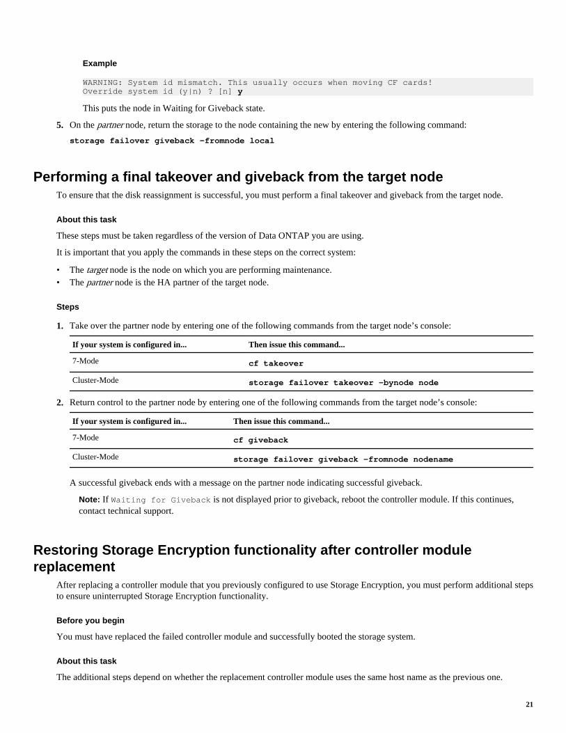
Example
WARNING: System id mismatch. This usually occurs when moving CF cards!Override system id (y|n) ? [n] y
This puts the node in Waiting for Giveback state.
5. On the partner node, return the storage to the node containing the new by entering the following command:
storage failover giveback -fromnode local
Performing a final takeover and giveback from the target nodeTo ensure that the disk reassignment is successful, you must perform a final takeover and giveback from the target node.
About this task
These steps must be taken regardless of the version of Data ONTAP you are using.
It is important that you apply the commands in these steps on the correct system:
• The target node is the node on which you are performing maintenance.• The partner node is the HA partner of the target node.
Steps
1. Take over the partner node by entering one of the following commands from the target node’s console:
If your system is configured in... Then issue this command...
7-Mode cf takeover
Cluster-Mode storage failover takeover -bynode node
2. Return control to the partner node by entering one of the following commands from the target node’s console:
If your system is configured in... Then issue this command...
7-Mode cf giveback
Cluster-Mode storage failover giveback -fromnode nodename
A successful giveback ends with a message on the partner node indicating successful giveback.
Note: If Waiting for Giveback is not displayed prior to giveback, reboot the controller module. If this continues,contact technical support.
Restoring Storage Encryption functionality after controller modulereplacement
After replacing a controller module that you previously configured to use Storage Encryption, you must perform additional stepsto ensure uninterrupted Storage Encryption functionality.
Before you begin
You must have replaced the failed controller module and successfully booted the storage system.
About this task
The additional steps depend on whether the replacement controller module uses the same host name as the previous one.
21

If it does, then it can use the same configuration, that is, SSL certificates and IP addresses for key management servers, toreconnect to the key management servers and resume operations. You should always update the authentication key by using thekey_manager rekey command after replacing a controller module. Updating the authentication key ensures that any attributesused by the HA pair (if present) are properly updated. Failure to update the authentication key could prevent a node fromretrieving the correct authentication key, thus being unable to boot the storage system.
If the new controller module uses a different host name, you must first generate new SSL certificates for the storage system,install them on the storage system and the key management server(s), and then use the key_manager setup command toreconfigure Storage Encryption. These steps are necessary to reestablish connectivity between the storage system and the keymanagement server(s).
Step
1. Perform one of the following actions:
If the replacement controllermodule...
Then...
Uses the same host name, IPaddress, and SSL certificates asthe previous controller module
Enter the following command:
key_manager rekey -key_tag key_tag
The key_tag is the label used to associate keys with a particular storage system. If you do notspecify a key tag, the storage system uses the key tag specified when you ran the Storage Encryptionsetup wizard. If you did not specify a key tag, the system uses the parent key tag as the default. Eachnode has a parent key tag. Nodes share the same parent key tag.
Uses a different host name thanthe previous controller module
a. Generate new SSL certificates for the storage system.
b. Install the new SSL certificates on the storage system and key management servers.
c. Enter the following command to reconfigure Storage Encryption:
key_manager setup
For more information, see the Data ONTAP 7-Mode Software Setup Guide
Completing the replacement processAfter you replace the part, you can return the failed part to NetApp, as described in the RMA instructions shipped with the kit.Contact technical support at 888-463-8277 (North America), 00-800-44-NETAPP (Europe), or +800-800-80-800 (Asia/Pacific)if you need the RMA number or additional help with the replacement procedure.
Disposing of batteriesDispose of batteries according to local regulations regarding battery recycling or disposal. If you cannot properly dispose of thebattery, return it to NetApp, as described in the RMA instructions shipped with the kit.
Related information
Warranty Agreement, Safety Information, and Regulatory Notices: now.netapp.com/NOW/knowledge/docs/hardware/hardware_index.shtml
Trademark information
NetApp, the NetApp logo, Network Appliance, the Network Appliance logo, Akorri, ApplianceWatch, ASUP, AutoSupport,BalancePoint, BalancePoint Predictor, Bycast, Campaign Express, ComplianceClock, Cryptainer, CryptoShred, Data ONTAP,DataFabric, DataFort, Decru, Decru DataFort, DenseStak, Engenio, Engenio logo, E-Stack, FAServer, FastStak, FilerView,FlexCache, FlexClone, FlexPod, FlexScale, FlexShare, FlexSuite, FlexVol, FPolicy, GetSuccessful, gFiler, Go further, faster,Imagine Virtually Anything, Lifetime Key Management, LockVault, Manage ONTAP, MetroCluster, MultiStore, NearStore,
22 Replacing a controller module in a 2240 system

NetCache, NOW (NetApp on the Web), Onaro, OnCommand, ONTAPI, OpenKey, PerformanceStak, RAID-DP, ReplicatorX,SANscreen, SANshare, SANtricity, SecureAdmin, SecureShare, Select, Service Builder, Shadow Tape, Simplicity, SimulateONTAP, SnapCopy, SnapDirector, SnapDrive, SnapFilter, SnapLock, SnapManager, SnapMigrator, SnapMirror, SnapMover,SnapProtect, SnapRestore, Snapshot, SnapSuite, SnapValidator, SnapVault, StorageGRID, StoreVault, the StoreVault logo,SyncMirror, Tech OnTap, The evolution of storage, Topio, vFiler, VFM, Virtual File Manager, VPolicy, WAFL, Web Filer, andXBB are trademarks or registered trademarks of NetApp, Inc. in the United States, other countries, or both.
IBM, the IBM logo, and ibm.com are trademarks or registered trademarks of International Business Machines Corporation inthe United States, other countries, or both. A complete and current list of other IBM trademarks is available on the Web at www.ibm.com/legal/copytrade.shtml.
Apple is a registered trademark and QuickTime is a trademark of Apple, Inc. in the U.S.A. and/or other countries. Microsoft is aregistered trademark and Windows Media is a trademark of Microsoft Corporation in the U.S.A. and/or other countries.RealAudio, RealNetworks, RealPlayer, RealSystem, RealText, and RealVideo are registered trademarks and RealMedia,RealProxy, and SureStream are trademarks of RealNetworks, Inc. in the U.S.A. and/or other countries.
All other brands or products are trademarks or registered trademarks of their respective holders and should be treated as such.
NetApp, Inc. is a licensee of the CompactFlash and CF Logo trademarks.
NetApp, Inc. NetCache is certified RealSystem compatible.
23