Embed Size (px)
Citation preview
Fisheries Occasional Publication No. 114, 2013
Report 1
In-water hull cleaning and filtration system: In-water cleaning trials 26-28 November 2012

Department of Fisheries 3rd floor SGIO Atrium168 - 170 St Georges TerracePERTH WA 6000Telephone: (08) 9482 7333Facsimile: (08) 9482 7389Website: www.fish.wa.gov.auABN: 55 689 771
© Department of Fisheries, Western Australia. July 2013. ISSN: 1447 - 2058 ISBN: 978-1-921845-62-8
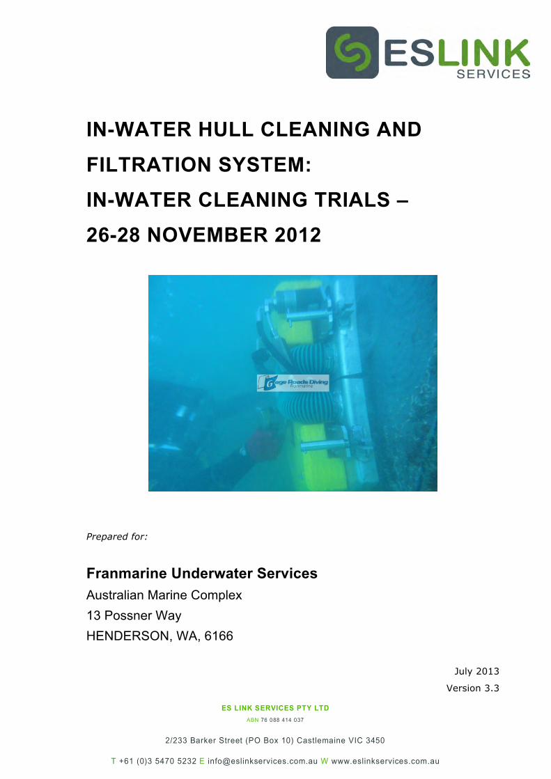
IN-WATER HULL CLEANING AND
FILTRATION SYSTEM:
IN-WATER CLEANING TRIALS –
26-28 NOVEMBER 2012
Prepared for:
Franmarine Underwater Services
Australian Marine Complex
13 Possner Way
HENDERSON, WA, 6166
July 2013
Version 3.3

Franmarine In-Water Cleaning Trials
Page i
IN-WATER HULL CLEANING AND
FILTRATION SYSTEM:
IN-WATER CLEANING TRIALS –
26-28 NOVEMBER 2012
Prepared for:
Franmarine Underwater Services
Australian Marine Complex
13 Possner Way
HENDERSON, WA, 6166
As part of trial outcome obligations set by
Department of Fisheries Western Australia
July 2013
Version 3.3
Prepared by:
John A Lewis
Principal Marine Consultant
ES Link Services Pty Ltd
Franmarine In-Water Cleaning Trials
Page ii
Franmarine In-Water Cleaning Trials
Page iii
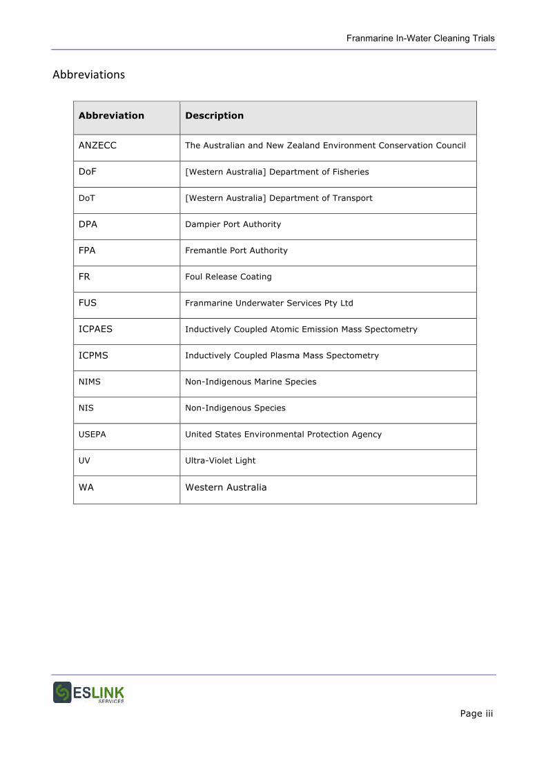
Abbreviations
Abbreviation Description
ANZECC The Australian and New Zealand Environment Conservation Council
DoF [Western Australia] Department of Fisheries
DoT [Western Australia] Department of Transport
DPA Dampier Port Authority
FPA Fremantle Port Authority
FR Foul Release Coating
FUS Franmarine Underwater Services Pty Ltd
ICPAES Inductively Coupled Atomic Emission Mass Spectometry
ICPMS Inductively Coupled Plasma Mass Spectometry
NIMS Non-Indigenous Marine Species
NIS Non-Indigenous Species
USEPA United States Environmental Protection Agency
UV Ultra-Violet Light
WA Western Australia

Franmarine In-Water Cleaning Trials
Page iv
Franmarine In-Water Cleaning Trials
Page 1
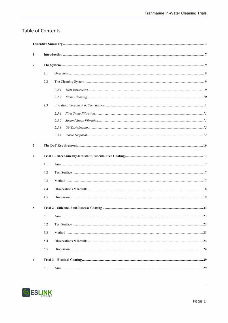
Table of Contents
Executive Summary .................................................................................................................................................................... 3
1 Introduction .................................................................................................................................................................... 7
2 The System ...................................................................................................................................................................... 9
2.1 Overview .............................................................................................................................................................. 9
2.2 The Cleaning System ........................................................................................................................................... 9
2.2.1 MkII Envirocart ....................................................................................................................................... 9
2.2.2 Niche Cleaning ...................................................................................................................................... 10
2.3 Filtration, Treatment & Containment ................................................................................................................ 11
2.3.1 First Stage Filtration ............................................................................................................................. 11
2.3.2 Second Stage Filtration ......................................................................................................................... 11
2.3.3 UV Disinfection ..................................................................................................................................... 12
2.3.4 Waste Disposal ...................................................................................................................................... 12
3 The DoF Requirement .................................................................................................................................................. 16
4 Trial 1 – Mechanically-Resistant, Biocide-Free Coating .......................................................................................... 17
4.1 Aim .................................................................................................................................................................... 17
4.2 Test Surface ....................................................................................................................................................... 17
4.3 Method ............................................................................................................................................................... 17
4.4 Observations & Results ..................................................................................................................................... 18
4.5 Discussion .......................................................................................................................................................... 19
5 Trial 2 – Silicone, Foul-Release Coating .................................................................................................................... 23
5.1 Aim .................................................................................................................................................................... 23
5.2 Test Surface ....................................................................................................................................................... 23
5.3 Method ............................................................................................................................................................... 23
5.4 Observations & Results ..................................................................................................................................... 24
5.5 Discussion .......................................................................................................................................................... 24
6 Trial 3 – Biocidal Coating ............................................................................................................................................ 29
6.1 Aim .................................................................................................................................................................... 29
Franmarine In-Water Cleaning Trials
Page 2
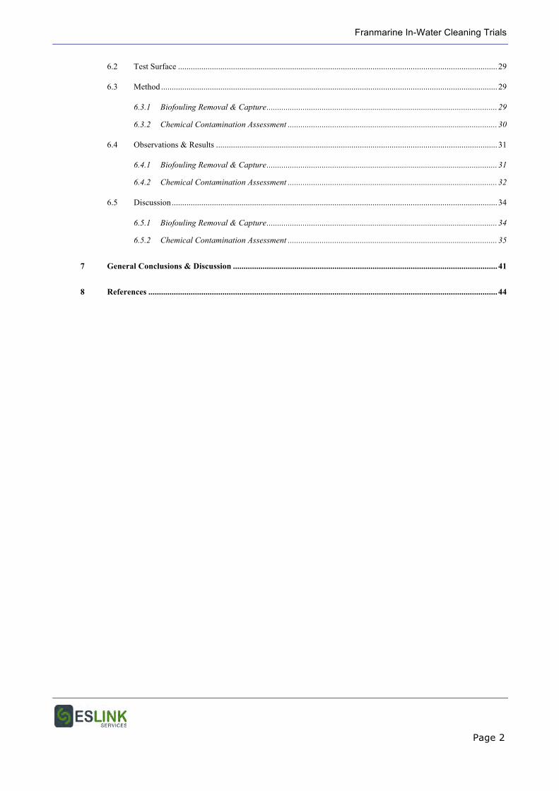
6.2 Test Surface ....................................................................................................................................................... 29
6.3 Method ............................................................................................................................................................... 29
6.3.1 Biofouling Removal & Capture ............................................................................................................. 29
6.3.2 Chemical Contamination Assessment ................................................................................................... 30
6.4 Observations & Results ..................................................................................................................................... 31
6.4.1 Biofouling Removal & Capture ............................................................................................................. 31
6.4.2 Chemical Contamination Assessment ................................................................................................... 32
6.5 Discussion .......................................................................................................................................................... 34
6.5.1 Biofouling Removal & Capture ............................................................................................................. 34
6.5.2 Chemical Contamination Assessment ................................................................................................... 35
7 General Conclusions & Discussion ............................................................................................................................. 41
8 References ..................................................................................................................................................................... 44
Franmarine In-Water Cleaning Trials
Page 3
EXECUTIVE SUMMARY
The settlement and growth of marine organisms (biofouling) on the underwater surfaces of
vessels not only increases hull drag, and consequently fuel consumption and greenhouse gas
emission, but also facilitates the translocation of potentially invasive marine species. Biofouling
prevention or minimisation is most commonly achieved by the application of antifouling
coatings, which prevent the settlement of marine organisms through the continuous release of
a biocide or biocides at the paint surface but, often, biofouling can develop in unprotected or
poorly protected niche areas, or on ineffective or depleted antifouling coating systems.
The most effective method for removal of biofouling from a vessel is to dry-dock or slip the
vessel and physically remove the growth by high pressure water blasting, grit blasting and/or
manual scraping, with all debris contained within the dock or around the vessel and disposed
on-shore. However, dry-docking or slipping is costly and not always feasible and in these
circumstances, rather than requiring the vessel to depart and move the problem elsewhere,
methods for in-water containment and treatment or removal and capture would provide a
useful tool to counter the biosecurity risk. Uncontrolled in-water cleaning may increase the risk
of incursion by stimulating the release of reproductive propagules, or plant and animal
fragments capable of regeneration. More generally, in-water cleaning can release chemical and
biological contaminants into the local environment, and environmental protection is best
achieved if these wastes can be contained and captured. No proven technology is yet on the
market to satisfactorily achieve this aim (Floerl et al 2010).
In response to this identified need, in mid-2011, the WA Department of Fisheries issued a
request for a service provider to develop a system for trials for the in-water treatment and
removal of marine biofouling by vessel encapsulation and cleaning technologies to kill and
remove biofouling from large (40m+) vessels.
Franmarine Underwater Services Pty Ltd had already designed and built a prototype
lightweight, portable hull cleaning system deemed capable of meeting this requirement and the
prototype was assessed in 3 trials in Perth on 26-28 November 2012.
Three separate trials were undertaken to assess the performance of the Franmarine in-water
cleaning system. The first trial was to demonstrate the level of biofouling removal, extent of
capture, and containment of debris > 50 µm in diameter from a heavily fouled, non-toxic
Franmarine In-Water Cleaning Trials
Page 4
underwater surface; the second to determine the occurrence of any physical damage to a
biocide-free, silicone foul-release coating from the cleaning cart; and the third to demonstrate
the level of biofouling removal, the extent of capture and containment of debris > 50 µm in
diameter, and the control and containment of released copper during cleaning of a vessel hull
painted with a copper-based antifouling coating.
The first trial was undertaken on the floating dry-dock, Yargan at the Australian Marine
Complex, Henderson, WA, on 26 November 2012. The underwater surfaces of the Yargan were
painted with a high performance epoxy protective coating, but no antifouling. In this trial the
Envirocart in-water cleaning system was demonstrated to be effective in removing established
primary and secondary biofouling from the flat vertical sides and bottom of the dock, capturing
all biological waste removed from the hull, and filtering out and capturing all biological debris
and other matter > 50 µm in diameter. The Envirocart did not completely remove biofouling
from alongside hull irregularities, such as weld lines, nor completely remove all calcareous
biofouling baseplates. However, these areas could be cleaned by follow-up cleaning with the
system’s hand tools.
The second trial was undertaken on a test panel coated in a silicone foul-release coating that
had been immersed for 10 months at the Austal Ships facility at Henderson, WA, on 27
November 2012. In a previous trial, the Envirocart had caused some unacceptable scuffing of
the coating surface. In this trial all biofouling was effectively removed from the silicone
surface, but there was again some mechanical damage to the surface. Scratches were caused
by the hard plastic jockey wheel jamming and dragging across the surface, and scuffing and
light radial scratching caused by one of the cleaning discs not being securely attached. No
damage was caused by the other, securely attached, cleaning disc. Both of these problems
appear easily rectifiable, but a further trial is necessary after the repairs and modifications to
demonstrate that the system is safe to use on foul-release coatings.
The third trial was undertaken on the hull of the Svitzer tug Wambiri in Fremantle Port on 28
November 2012. The underwater hull of the Wambiri was painted with a copper-based
antifouling coating. In addition to the cleaning trials, water samples were taken for chemical
analysis from close to the hull before, during and after the trial to determine if copper was
released during the clean, and from the treatment system effluent. The Envirocart, “magic
box” and hand cleaning tools were all demonstrated in this trial to effectively remove, capture
and contain biofouling growth from hull and other underwater surfaces and structures.
Franmarine In-Water Cleaning Trials
Page 5
Difficulties encountered in securing the “magic box” to the hull, and in capturing all heavy
fouling when hand scraping are considered easily rectified by minor design modifications.
Analysis of the water samples showed no suggestion of any elevation of copper or other heavy
metals in the water column adjacent to the vessel during or after the cleaning trial. Significant
levels of copper were measured in samples of the effluent from the biological treatment
system, but with levels much lower when using the blade discs then the brushes. Estimation of
the total copper that would be entrained in the effluent during a full clean of a hull of a similar
size to the Wambiri indicate that, if discharged, it would amount to less than that passively
released in one day from the antifouling coating of a commercial ship berthed in the port.
Overall, these trials of the Franmarine in-water hull cleaning and filtration system
demonstrated the system to be effective in removing, capturing and containing biofouling and
other debris > 50 µm in diameter, from vessel surfaces coated with either hard, non-biocidal
protective coatings or biocidal antifouling coatings. For the latter, chemical contamination
assessment indicated that copper-containing effluent from the cleaning was at a level unlikely
to cause harm if discharged directly into adjacent water body.
Franmarine In-Water Cleaning Trials
Page 6
Franmarine In-Water Cleaning Trials
Page 7
1 INTRODUCTION
The settlement and growth of marine organisms on the underwater surfaces of vessels
increases drag, and consequently fuel consumption and greenhouse gas emissions, and can
facilitate the translocation of potentially invasive marine species. Biofouling prevention or
minimisation is most commonly achieved by the application of antifouling coatings, which
prevent the settlement of biofouling organisms through the continuous release of a biocide or
biocides at the paint surface. In recent times, non-toxic foul release coatings, which do not
prevent but minimise the strength of adhesion of biofouling, and hard, scrubbable coatings
that require regular cleaning to prevent biofouling accretion, have also been adopted as
alternatives to biocidal antifouling coatings.
In-water cleaning of the immersed hulls of vessels can be warranted to:
• Remove slime and biofouling to improve hull and fuel efficiency;
• Remove biofouling growth after periods of vessel lay-up or low activity;
• Maintain foul release or scrubbable coatings; and
• Contain and remove potentially invasive marine species.
Invasive non-indigenous species (NIS), along with habitat destruction, have been considered
to be the leading cause of species extinctions and biodiversity loss worldwide. Within the
marine realm, non-indigenous marine species (NIMS) have been cited as one of the top five
threats to marine ecosystem function and biodiversity. A significant, and possibly the most
significant, ongoing vector for the translocation of NIMS across natural marine biogeographic
boundaries is now acknowledged to be biofouling of vessel hulls. Australia’s evolutionary
isolation and high marine diversity and endemism has placed it at risk of invasion by exotic
marine species, and invasive marine species can create environmental, economic, human
health and socio-cultural impacts. The eradication of NIMS from the natural environment,
even on first detection, is rarely possible and the most effective strategy is to proactively
minimise the risk of NIMS translocation through the minimisation and management of vessel
biofouling. However, should a NIMS considered to present a new risk be detected on a vessel
on, or soon after arrival in a location, containment of that individual or population on the
vessel could prevent the release of reproductive propagules that could colonise the local
environment.
Franmarine In-Water Cleaning Trials
Page 8
The most effective method for removal of biofouling from a vessel is to dry-dock or slip the
vessel and physically remove the growth by high pressure water blasting, grit blasting and/or
manual scraping, with all debris contained within the dock or around the vessel and disposed
on-shore. However, dry-docking or slipping is not always feasible and in these circumstances,
rather than requiring the vessel to depart and move the problem elsewhere, methods for in-
water containment and treatment or removal and capture would provide a useful tool to
counter the biosecurity risk. Uncontrolled in-water cleaning may increase the risk of incursion
by stimulating the release of reproductive propagules, or plant and animal fragments capable
of regeneration. More generally, in-water cleaning can release chemical and biological
contaminants into the local environment, and environmental protection is best achieved if
these wastes can be contained and captured. No proven technology is yet on the market to
satisfactorily achieve this aim (Floerl et al. 2010).
In mid-2011, the WA Department of Fisheries issued a request for a service provider to
develop a system for trials for the in-water treatment and removal of marine biofouling by
vessel encapsulation and cleaning technologies to kill and remove biofouling from large
(40m+) vessels. The system would be required to stand alone and meet all government
requirements including, but not limited to, those imposed by the Department of Transport
(DoT) and the Dampier Port Authority (DPA).
Franmarine Underwater Services Pty Ltd (Franmarine) has designed and built a lightweight,
portable hull cleaning system that removes and captures marine growth from a vessel or other
underwater surface through a fully enclosed suction system. Franmarine was successful in
proposing this system in response to the DoF request, and was funded to proceed with trials.
Initial trials of the prototype system demonstrated considerable promise, and warranted
further, more detailed testing and trials to demonstrate that the system could meet the DoF
requirement.
This report describes practical trials of the Franmarine in-water cleaning system in Perth
waters on 26, 27 and 28 November 2012.
Franmarine In-Water Cleaning Trials
Page 9
2 THE SYSTEM
2.1 Overview
The primary tool for the removal of marine growth from flat or curved underwater surfaces is
the “Envirocart”; a diver-steered, hydraulically-powered unit with twin rotating discs that can
be fitted with either brushes or blades. For less regular surfaces, shrouded hand tools, and a
containment box have been designed. Each cleaning tool has a suction shroud that connects
separately to the central, fully enclosed suction system through which debris is pumped onto
the support vessel or wharf for treatment.
Extracted water and debris is the processed through a multi-staged, modular filtration and
treatment systems where biofouling debris and particles are removed, then the filtrate passed
through an automated UV disinfection unit.
2.2 The Cleaning System
2.2.1 MkII Envirocart
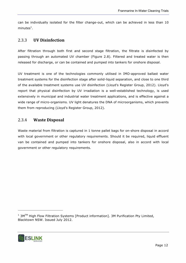
The MkII Envirocart has two counter-rotating discs to which 300 mm diameter brushes or
bladed discs are attached (Figure 2.1). The discs are hydraulically driven, and the total width
of clean in one pass is 700 mm. The chassis and drive systems both have scissor actions that
enable the cart to clean flat and curved surfaces including, for example, the turn of the bilge.
The lower rim of the cart body is fringed by a shroud of dense, flexible bristles that act to
contain debris within the area of suction, and there are two forward wheels and a rear jockey
wheel for movement and manoeuvrability across the surface to be cleaned. Suction of debris
is generated by the submersible trash pump and hydrodynamic vortices generated by the
brushes, and water and material is drawn through ports to a central and two lateral suction
lines which lead into the 4” hose to the trash pump (Figures 2.2, 2.3). A foam float is fitted to
the upper side of the cart to provide neutral buoyancy of the unit underwater (Figure 2.3).
Different cleaning discs and wheels can be fitted to the cart for different cleaning tasks. These
include:
Franmarine In-Water Cleaning Trials
Page 10
• Combination steel and nylon bristle brushes for heavy fouling removal on scrubbable,
biocide-free coatings or other hard substrates (Figure 2.1);
• All nylon bristles for biocidal conventional or copolymer antifouling coatings; and
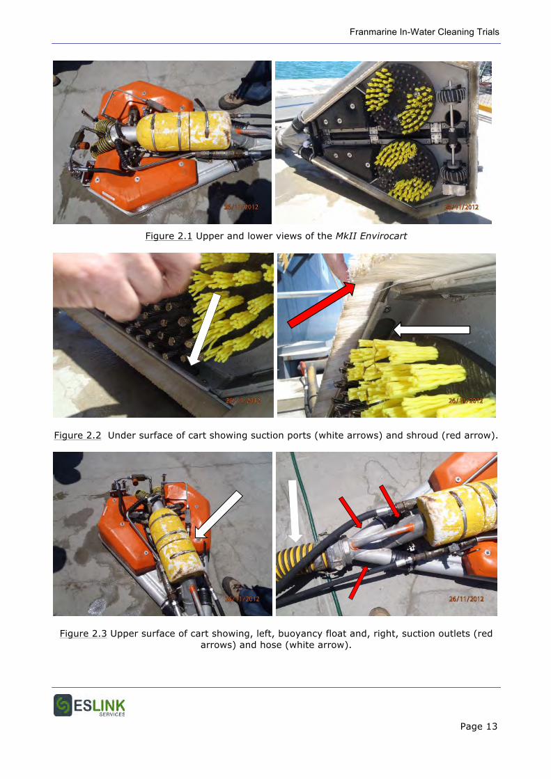
• 45o nylon blades for contactless cleaning (Figure 2.4).
The Envirocart has a top speed of 1.5 knots and has the capability to clean 1000 m2 per 6 hour
day.
2.2.2 Niche Cleaning
The brush cart cannot clean irregular hull surfaces, invaginations or protrusions of the hull, and
hull appendages. For the cleaning of these, the trash pump is fitted with an additional 2” hose
for attachment of interchangeable niche cleaning tools. Each tool has a suction shroud that
connects separately to the central suction system which allows multiple, concurrent cleaning
tasks.
Hand- Scrapers with Shroud
For small areas, such as along weld lines and bilge keels, shrouded hand scrapers have been
designed. Two sizes, 40 mm and 100 mm blade width scrapers are currently available (Figure
2.5).
Magic Box
The “magic box” is a transparent plastic box that can be centrally hooked onto a removable
magnetic hull attachment or to an anode or other hull appendage. The box then seals onto the
hull when suction is applied from the 2” suction hose to the trash pump. Access ports in the
box walls allow a high pressure (5000 psi) water lance to be inserted to clean biofouling from
the enclosed surfaces.
Submersible Hydraulic Trash Pump
The capacity of suction system has been demonstrated in trials to be 3000 l/min of
contaminated water.
Franmarine In-Water Cleaning Trials
Page 11
2.3 Filtration, Treatment & Containment
2.3.1 First Stage Filtration
The trash pump lifts water and debris through a 4” hose to the first stage filtration system.
This unit comprises a feed box which allows a consistent flow of feed slurry onto an inclined,
static woven mesh screen (the Baleen Filter ®) (Figure 2.6). Mesh size on the prototype unit is
50 µm, although finer mesh could potentially be used. Any oversize or near-size particles
(including viscous emulsion, if present) are retained on the screen surface and the slurry
filtrate passes through the mesh screen by gravity. The oversize material is fluidised from the
screen surface by a low volume, high pressure water spray bar located below the surface of
the screen and perpendicular to it (Figure 2.7). Concurrently, a similar spray bar located above
the screen surface, and at a slightly forward orientation, flushes the fluidised bed of oversize
material to the discharge end of the screen for collection in a disposable bin bag.
The connected top and bottom spray bars travel down the screen in a pneumatically-driven
carriage system. When the carriage reaches the lower limit of travel at the lower end of the
screen, the spray water is cut off and the carriage returns to the feed end of the screen for the
next cleaning cycle.
The entire unit is constructed of either stainless or duplex steel.
2.3.2 Second Stage Filtration
Filtrate from the first stage filtration is further filtered by pumping it through a series of four
back-flushable filter units that contain high volume, interchangeable, cartridge filters (3MTM
High Flow 40” filter cartridges, 25 µm media grade) capable of removing particulate material
greater in size than 2 – 5 µm (Figure 2.8). 3MTM internal laboratory testing determined the
removal efficiency of these cartridges to be 98.93% for 3-5 µm particles (A Ng, 3M Purification
Pty Ltd, personal communication 13 March 2012). The filters are regularly back-flushed when
resistance increases (in practice about every 25 min), with the back-flushed water discharged
back into the solids bin, drained, then recycled back through the filtration process. Back-
flushing and cleaning re-generates 60% of a filter’s efficiency, but ultimately the cartridges
reach a maximum operating back pressure and need to be replaced. Filter units in the series
Franmarine In-Water Cleaning Trials
Page 12
can be individually isolated for the filter change-out, which can be achieved in less than 10
minutes1.
2.3.3 UV Disinfection
After filtration through both first and second stage filtration, the filtrate is disinfected by
passing through an automated UV chamber (Figure 2.8). Filtered and treated water is then
released for discharge, or can be contained and pumped into tankers for onshore disposal.
UV treatment is one of the technologies commonly utilised in IMO-approved ballast water
treatment systems for the disinfection stage after solid-liquid separation, and close to one third
of the available treatment systems use UV disinfection (Lloyd’s Register Group, 2012). Lloyd’s
report that physical disinfection by UV irradiation is a well-established technology, is used
extensively in municipal and industrial water treatment applications, and is effective against a
wide range of micro-organisms. UV light denatures the DNA of microorganisms, which prevents
them from reproducing (Lloyd’s Register Group, 2012).
2.3.4 Waste Disposal
Waste material from filtration is captured in 1 tonne pallet bags for on-shore disposal in accord
with local government or other regulatory requirements. Should it be required, liquid effluent
van be contained and pumped into tankers for onshore disposal, also in accord with local
government or other regulatory requirements.
1 3MTM High Flow Filtration Systems [Product information]. 3M Purification Pty Limited, Blacktown NSW. Issued July 2012.
Franmarine In-Water Cleaning Trials
Page 13
Figure 2.1 Upper and lower views of the MkII Envirocart
Figure 2.2 Under surface of cart showing suction ports (white arrows) and shroud (red arrow).
Figure 2.3 Upper surface of cart showing, left, buoyancy float and, right, suction outlets (red arrows) and hose (white arrow).
Franmarine In-Water Cleaning Trials
Page 14
Figure 2.4 Cleaning heads with non-contact nylon blades.
Figure 2.5 40 mm (left) and 100 mm (right) shrouded hand-cleaning blades.
Figure 2.6 First stage filtration: filter screen
Franmarine In-Water Cleaning Trials
Page 15
Figure 2.7 First stage filtration: upper and lower spray bars
Figure 2.8 Second stage filtration assembly (left) and UV treatment unit (right).
Franmarine In-Water Cleaning Trials
Page 16
3 THE DOF REQUIREMENT
The DoF request specified that the successful Respondent must develop a system to conduct
trials that could evaluate and demonstrate the costs and benefits of using in-water
encapsulation for large marine vessels in comparison to conventional biofouling practices used
to prevent the introduction of invasive marine species to Western Australian waters. The
requirement was for the services of an operational system to undertake trials for the in-water
treatment and removal of marine biofouling. The system should be able to stand alone and
should meet all government requirements, including but not limited to those imposed by the
DoT and the DPA.
The specification was for the development of a trial system that:
• Is capable of safely and securely encapsulating and treating (killing and removing bio-
foul organisms in a timely manner) a range of vessels types and sizes;
• Is suitable for 40m vessels in the trial and that can be scaled to accommodate larger
vessels (55 m long);
• Is deployed in the Dampier region to service including but not be limited to, oil and gas
industry vessels;
• Tests a range of chemical and/or alternate (e.g. anoxia, freshwater) treatments to
neutralise marine bio-fouling;
• Includes a cost-benefit analysis that evaluates the efficacy and suitability
(environmental impact, cost, accessibility) of each treatment tested;
• Contains all treatment chemicals and bio-fouling organisms removed from vessel with
zero to minimal discharge and/or impact to the surrounding marine environment;
• Safely captures and removes all bio-fouling organisms and residue for analysis and safe
disposal;
• Uses novel techniques such as digital video and/or sonar imaging to provide a record of
the extent of biofouling on each vessel;
• Includes methods that are capable of killing and removing bio-foulers from all areas on
a vessel including the hull and vessel bottom, plus niche areas such as propellers,
propeller shafts and sea chest grates;
• Allows the DoF, or their representative, to conduct in-situ research to evaluate the
efficacy of the system and treatment methods used to kill and capture marine bio-
fouling organisms (approximately within one month of development); and
Franmarine In-Water Cleaning Trials
Page 17
• Includes practical considerations of using these technologies such as start-up and
running costs, accessibility and Occupational Health and Safety issues.
4 TRIAL 1 – MECHANICALLY-RESISTANT, BIOCIDE-
FREE COATING
4.1 Aim
To demonstrate the level of, and quantify, biofouling removal; the extent of capture, and
containment, of debris >50 µm in diameter.
4.2 Test Surface
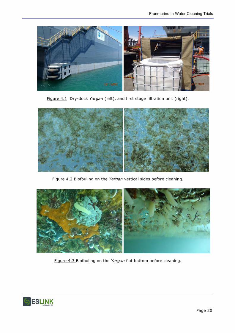
Trial 1 was undertaken on floating dry-dock Yargan, located at the Australian Marine Complex,
Henderson, WA (Figure 4.1). Yargan is constructed of steel and underwater surfaces are
painted with a high performance anti-corrosive marine paint system. The current top coat,
applied in November 2007, is a two component epoxy coating, PPG Sigmashield 420. No
antifouling coating, either biocidal or biocide-free, was applied.
4.3 Method
The Yargan trials were conducted on 26 November 2012, with the filtration and treatment
system located on the cross-wharf adjacent to the dry-dock (Figure 4.1). The Envirocart was
fitted with brushes having half firm nylon, and half steel bristles. The second stage filtration
system was not connected for this trial, so filtrate from the 50 µm filter passed directly into the
UV unit and was then discharged.
Two areas were cleaned: and an area on the vertical side of the dock, from chine to waterline,
and an area on the flat bottom. Digital still photographs of these areas were taken prior and
subsequent to the clean. The operator of the Envirocart wore a helmet-mounted video camera,
and video during the clean was monitored live dock-side, and recorded.
Franmarine In-Water Cleaning Trials
Page 18
4.4 Observations & Results
Prior to cleaning, the vertical underwater sides of the Yargan were approximately 75 – 100%
covered by secondary biofouling comprising predominantly filamentous hydroids and
macroalgae (Figure 4.2). Some scattered juvenile mytilid mussels had settled on to this
filamentous growth. In contrast, the flat bottom was heavily colonised by a diverse and well-
developed community of secondary foulers including sponges, solitary and colonial ascidians,
and serpulid tubeworms, and on this there were some attached scallops (Figure 4.3).
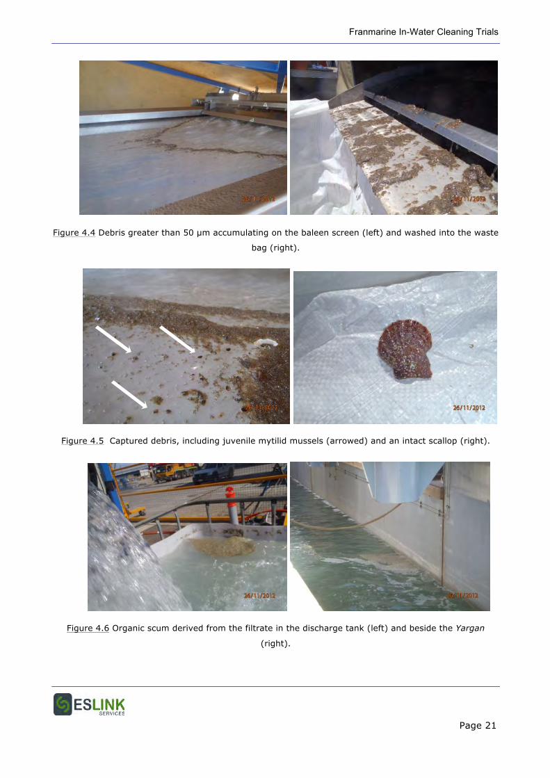
During the clean, the biological debris removed from the hull was clearly evident on the first
stage filter screen and being washed into the waste bag (Figure 4.4). Most of the growth on
the filter was crushed or mashed, but many small mussels came through unbroken. Some
larger bivalves and small fish passed through the pump and onto the screen intact and alive
(Figure 4.5). The only indication of organic matter passing through the filtration process was
the formation of a scum and foam on the surface of the discharge tank and around the
discharged water plume (Figure 4.6). This was green when green macroalgae were being
cleaned from the surface and appeared to be either spores or cell contents, and brown at other
times suggesting fine silt or clay particles or disassociated organic matter (Figure 4.6).
Microscopic examination of material collected from the scum in the discharge tank found
predominantly disaggregated organic matter, with a few recognisable diatoms. No particulates
greater than 12.5 µm were seen, and particles approaching this size were uncommon.
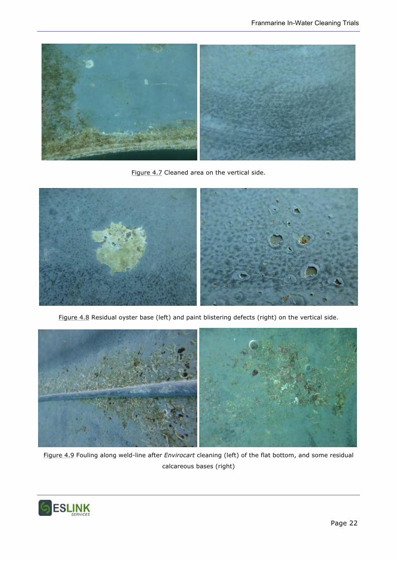
After cleaning, smooth areas of hull plate were mostly visibly free of biofouling on both the
vertical sides (Figure 4.7) and flat bottom (Figure 4.8). Biofouling encrustation did persist
alongside hull irregularities, such as weld-lines, but on the flat hull plate only some scattered
and isolated calcareous baseplate scars of oysters and tubeworms remained (Figure 4.9). The
only mechanical damage to the coating from the cleaning was light scuffing from contact of the
brushes. These would not compromise coating life or performance.
No biological debris was observed to escape from around the Envirocart. An experiment was
undertaken to determine the area of suction and containment of water and debris around the
perimeter of the cart. Blue food dye was squirted into the water in a line extending out from
the shroud. The distance to which water and dye was drawn under the shroud was
approximately 150 mm.
Franmarine In-Water Cleaning Trials
Page 19
4.5 Discussion
The Envirocart in-water cleaning system was effective in:
1. Removing established primary and secondary biofouling from the flat vertical sides and
bottom of the Yargan;
2. Capturing all biological waste removed from the hull; and
3. Filtering out and capturing all biological debris and other matter > 50 µm in diameter.
The brush cart system did not:
1. Remove biofouling from alongside hull irregularities, such as weld lines; and
2. Completely remove all calcareous baseplates.
However, these areas could readily be cleaned using the manual niche cleaning tools.
In addition, fine organic material passing through the system was lifted to the surface of the
water by entrained fine bubbles in the discharge tank and formed a surface scum. Some of this
was discharged and formed a small plume in the seawater around the discharge stream.
Franmarine In-Water Cleaning Trials
Page 20
Figure 4.1 Dry-dock Yargan (left), and first stage filtration unit (right).
Figure 4.2 Biofouling on the Yargan vertical sides before cleaning.
Figure 4.3 Biofouling on the Yargan flat bottom before cleaning.
Franmarine In-Water Cleaning Trials
Page 21
Figure 4.4 Debris greater than 50 µm accumulating on the baleen screen (left) and washed into the waste
bag (right).
Figure 4.5 Captured debris, including juvenile mytilid mussels (arrowed) and an intact scallop (right).
Figure 4.6 Organic scum derived from the filtrate in the discharge tank (left) and beside the Yargan
(right).
Franmarine In-Water Cleaning Trials
Page 22
Figure 4.7 Cleaned area on the vertical side.
Figure 4.8 Residual oyster base (left) and paint blistering defects (right) on the vertical side.
Figure 4.9 Fouling along weld-line after Envirocart cleaning (left) of the flat bottom, and some residual
calcareous bases (right)
Franmarine In-Water Cleaning Trials
Page 23
5 TRIAL 2 – SILICONE, FOUL-RELEASE COATING
5.1 Aim
To determine any physical damage to biocide-free, silicone foul-release coating caused by the
cleaning cart.
5.2 Test Surface
Cleaning trials were undertaken on a 2000 x 1000 mm aluminium plate painted with a full
silicone foul release (FR) system that had been immersed for 10 months from the edge of the
cross wharf at the Austal Ships facility at Henderson, WA. The FR coating applied was
International Intersleek 425 (red), over a tie-coat (Intersleek 386) and epoxy primer
(Intershield 300).
The painted panel was first immersed on January 2012. Initial cleaning trials of the MkII
Envirocart fitted with bladed cleaning discs were conducted on half of the panel on 20 Nov
2012. Some scuffing of the surface was observed, due to the blades touching the coating
surface, so a repeat trial was warranted after modifications to the cart to prevent contact.
5.3 Method
The trial was conducted with the test plate in its suspended position adjacent to the wharf.
The cart was positioned on the lower half of the panel with no part of the chassis overhanging
the edge of the panel. The clean was conducted by propelling the cart upwards on the long
axis of the panel. The first pass was with the left-hand brush over the previously cleaned area
of the panel and the right-hand brush on the uncleaned area. After the pass, the panel was
recovered, inspected, and returned for a second cleaning pass. On the second pass the left
hand brush was positioned over the area cleaned in the first pass, and the right hand brush
over the uncleaned portion near the right panel edge.
Franmarine In-Water Cleaning Trials
Page 24
5.4 Observations & Results
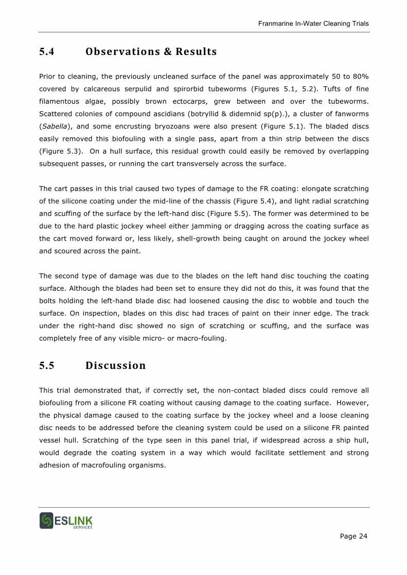
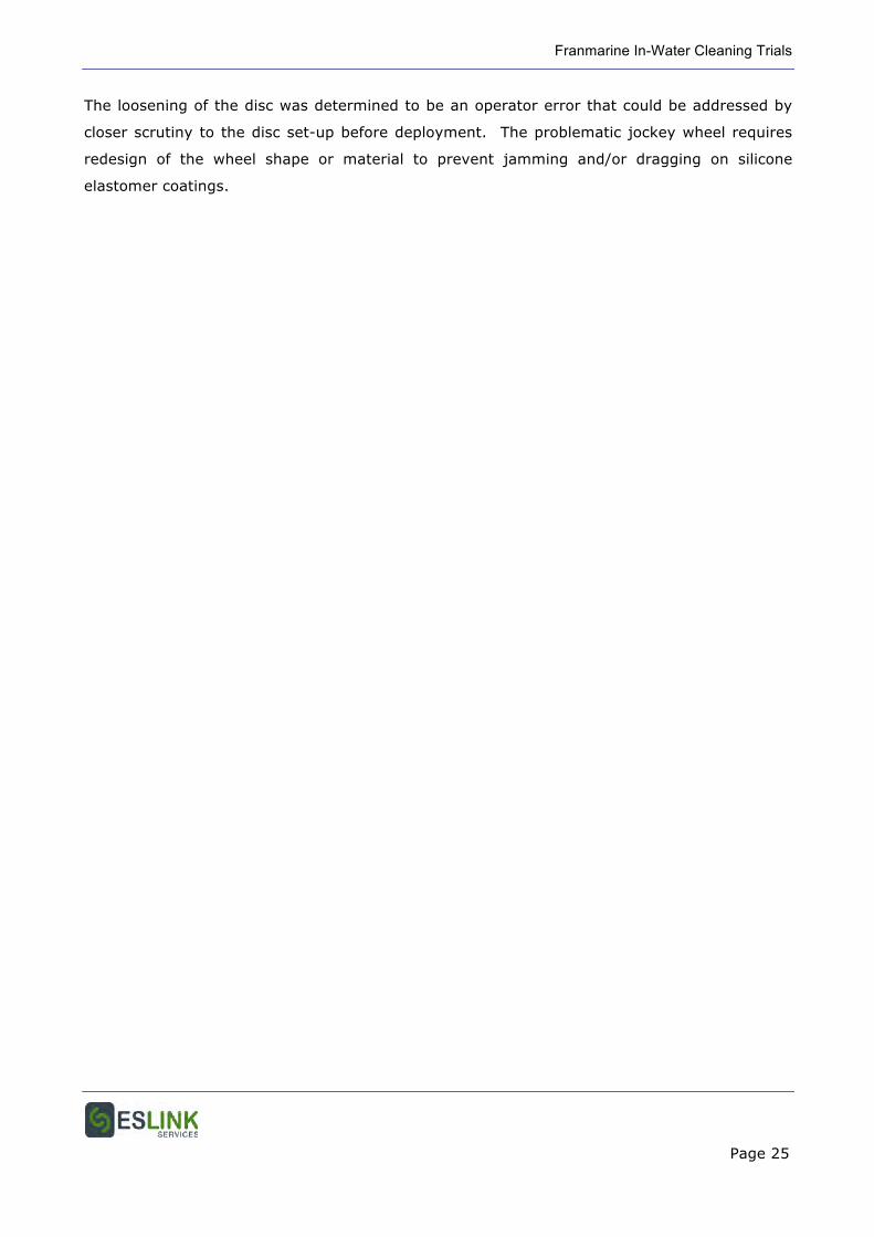
Prior to cleaning, the previously uncleaned surface of the panel was approximately 50 to 80%
covered by calcareous serpulid and spirorbid tubeworms (Figures 5.1, 5.2). Tufts of fine
filamentous algae, possibly brown ectocarps, grew between and over the tubeworms.
Scattered colonies of compound ascidians (botryllid & didemnid sp(p).), a cluster of fanworms
(Sabella), and some encrusting bryozoans were also present (Figure 5.1). The bladed discs
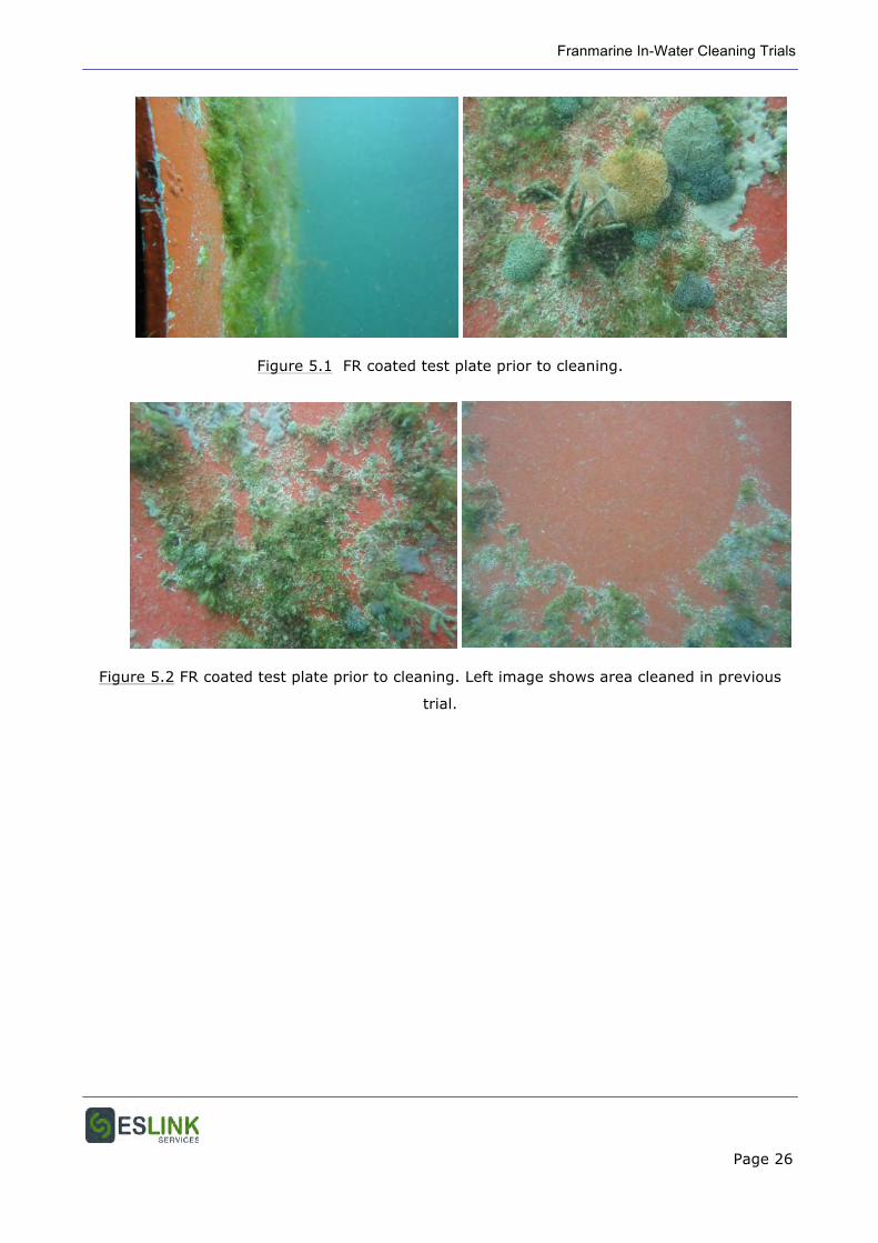
easily removed this biofouling with a single pass, apart from a thin strip between the discs
(Figure 5.3). On a hull surface, this residual growth could easily be removed by overlapping
subsequent passes, or running the cart transversely across the surface.
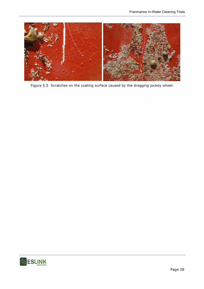
The cart passes in this trial caused two types of damage to the FR coating: elongate scratching
of the silicone coating under the mid-line of the chassis (Figure 5.4), and light radial scratching
and scuffing of the surface by the left-hand disc (Figure 5.5). The former was determined to be
due to the hard plastic jockey wheel either jamming or dragging across the coating surface as
the cart moved forward or, less likely, shell-growth being caught on around the jockey wheel
and scoured across the paint.
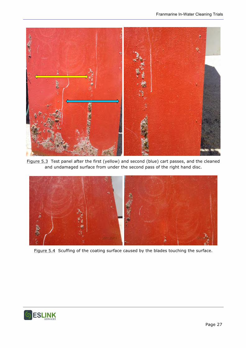
The second type of damage was due to the blades on the left hand disc touching the coating
surface. Although the blades had been set to ensure they did not do this, it was found that the
bolts holding the left-hand blade disc had loosened causing the disc to wobble and touch the
surface. On inspection, blades on this disc had traces of paint on their inner edge. The track
under the right-hand disc showed no sign of scratching or scuffing, and the surface was
completely free of any visible micro- or macro-fouling.
5.5 Discussion
This trial demonstrated that, if correctly set, the non-contact bladed discs could remove all
biofouling from a silicone FR coating without causing damage to the coating surface. However,
the physical damage caused to the coating surface by the jockey wheel and a loose cleaning
disc needs to be addressed before the cleaning system could be used on a silicone FR painted
vessel hull. Scratching of the type seen in this panel trial, if widespread across a ship hull,
would degrade the coating system in a way which would facilitate settlement and strong
adhesion of macrofouling organisms.
Franmarine In-Water Cleaning Trials
Page 25
The loosening of the disc was determined to be an operator error that could be addressed by
closer scrutiny to the disc set-up before deployment. The problematic jockey wheel requires
redesign of the wheel shape or material to prevent jamming and/or dragging on silicone
elastomer coatings.
Franmarine In-Water Cleaning Trials
Page 26
Figure 5.1 FR coated test plate prior to cleaning.
Figure 5.2 FR coated test plate prior to cleaning. Left image shows area cleaned in previous
trial.
Franmarine In-Water Cleaning Trials
Page 27
Figure 5.3 Test panel after the first (yellow) and second (blue) cart passes, and the cleaned and undamaged surface from under the second pass of the right hand disc.
Figure 5.4 Scuffing of the coating surface caused by the blades touching the surface.
Franmarine In-Water Cleaning Trials
Page 28
Figure 5.5 Scratches on the coating surface caused by the dragging jockey wheel.
Franmarine In-Water Cleaning Trials
Page 29
6 TRIAL 3 – BIOCIDAL COATING
6.1 Aim
To demonstrate the level of, and quantify, biofouling removal, the extent of capture and
containment of debris > 50 µm in diameter on a biocidal coating, and the control and
containment of released copper to be within local water quality discharge limits or other
requirements.
6.2 Test Surface
In addition to the requirements of the original DoF request (Section 3) and requirements of the
FUS Environmental Management Plan, DoF added requirements for this trial that the trial
vessel must be self-propelled, have sea chests and other niche areas, be 30+ m in length, and
have an antifouling coating less than 3 years old. The Svitzer tug MT Wambiri met these
requirements and approval gained to use this as the test vessel (Figure 6.1). Approval for the
trial was also granted by the FPA.
The antifouling coating on the Wambiri is Sigma Ecofleet 290 which was applied during a dry-
docking of the vessel 13 months earlier. Ecofleet 290 is a TBT-free self-polishing antifouling
coating that contains the biocides cuprous oxide and diuron. The hull of the Wambiri is fitted
with sacrificial cathodic protection (CP) anodes, and has sea chests and other niches prone to
biofouling accumulation.
6.3 Method
6.3.1 Biofouling Removal & Capture
Cleaning trials to remove growth from the hull were undertaken with the Envirocart fitted
firstly with bladed discs, and then brushes with soft nylon bristles. Suction water and cleaning
debris was passed through all treatment stages: first stage filtration, second stage filtration,
and UV treatment. However, additionally, all liquid filtrate was contained and pumped into
tanker trucks, as required for this trial by the Fremantle Port Authority (FPA). The clean
durations were 15 min with the bladed discs, and 15 min with the brush.
Franmarine In-Water Cleaning Trials
Page 30
A trial of the “magic box” was undertaken by positioning the box over a CP anode on the
Wambiri hull. When sealed in position over the anode, a high pressure (3000 psi) water lance
was inserted through the access ports in the box to jet biofouling form on and around the
anode.
The final trial of this set assessed the use of the 100 mm shrouded hand scraper. Rather than
demonstrating this on the hull, which had only primary biofouling, the scraper was used to
remove well developed biofouling from a wharf pile adjacent to the Wambiri.
6.3.2 Chemical Contamination Assessment
Prior to, and after the hull clean, water samples were collected by the divers at pre-planned
locations around, and distances out from the hull to primarily detect any elevation of seawater
copper concentrations from the hull cleaning. The sampling procedure, collection and
management was overseen by DoF personnel on-site2.
Water samples (n=204) were collected by divers at 2 depths (0.5 m and 2 m) at three
locations along the vessel: stern (0.5 m), midship (2 m) and bow (5 m). Five replicates were
taken at each depth and vessel location before, during and after cleaning. Due to weather
conditions, samples were taken at three different areas rather than different distances of the
vessel. An additional 24 samples were also taken from the post-UV treatment outflow reservoir
during cleaning: 14 when a bladed disc was fitted and 10 with a brush disc fitted.
After collection, samples were stored in ice and transported to the WA Chem Centre for
analysis. Prior to analysis, 500 mL of each sample was filtered through a 0.45 µm filter and the
quantity of analyte retained on the filter, and the concentration of analyte in the filtrate
measured. The amount of copper, cadmium, lead, tin and zinc in the samples were
determined. Total dissolved metals in the filtrate were determined by ICPMS and metals on the
filters by acid digestion and ICPMS or ICPAES.
2 Government of Western Australia, Department of Fisheries. In-water Cleaning Trial: Report of Sampling Activities. 15 January 2013.
Franmarine In-Water Cleaning Trials
Page 31
Statistical analysis was performed using the statistical package SPSS Statistics Version 17.0
(SPSS Inc.). Analysis of variance (ANOVA) was undertaken first, but including the test for
homogeneity of variances. If the significance of the latter test was less than 0.05, non-
parametric Mann-Whitney and Kruskal-Wallis tests were applied.
6.4 Observations & Results
6.4.1 Biofouling Removal & Capture
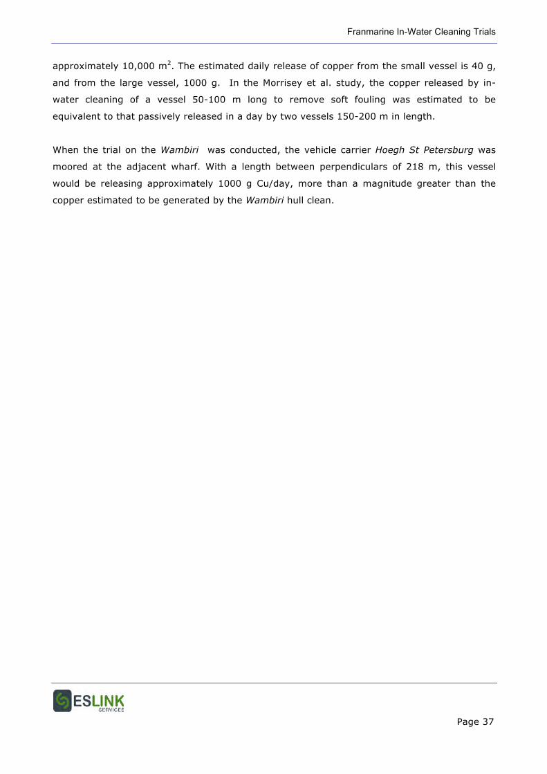
Before cleaning, the surface of the antifouling system on the underwater hull of the Wambiri
was covered by primary biofouling (= biofilm/microfouling/slime) (Figures 6.2, 6.3).
Microscopic examination of a sample taken from the debris on the first stage filtration screen
showed the biofouling (>50 µm component) to be primarily diatoms, small filamentous algae
and protozoa.
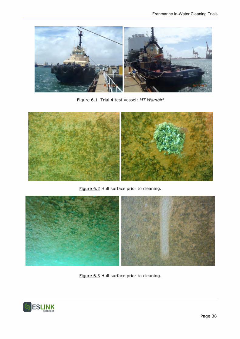
Cart cleaning with both the bladed disc and brushes completely removed the biofilm, and
caused no visible damage to the underlying coating (Figures 6.4, 6.5). No plume of either paint
or organic debris was visible around the cart during the clean. Removal of the biofilm and
leached surface layer of the paint would not cause accelerated deterioration or aging of the
antifouling system but, rather, regenerates the antifouling mechanism by restoring the biocide
leach rate to, or close to the design rate for the system
Filtrate from the treatment process was visibly (red) coloured during cleaning with both blades
and brushes (Figure 6.6), with the colour much more intense during brush cleaning.
Cleaning of the CP anode using the magic box and high pressure water jetting was effective in
removing all visible biofouling from on and around the anode (Figure 6.7). No debris or plume
was observed to escape the enclosure during the clean, and debris accumulating in the box
was seen to be extracted through the suction hose to the trash pump.
Some initial difficulties were experienced in securing the box to the hull around the anode prior
to the application of suction which holds and seals the box in position. The box is designed
with a central, internal, bendable hook designed to be hooked behind an anode, grate bar or
other niche appendage. However the anode chosen did not have sufficient clearance from the
Franmarine In-Water Cleaning Trials
Page 32
hull for insertion of the hook. A magnetic block was therefore placed beside the anode but,
with this, there were still some difficulties in attaching the box due to the “hook” straightening
and releasing.
Removal of biofouling growth from the wharf pile with the shrouded blade was effective and
growth scraped from the surface was drawn into the suction pipe. The observed limitation of
the technique related to the severity and thickness of the fouling on the surface. The depth of
the fouling exceeded the height of the shroud, and the diver was required to hold clumps of
fouling as they were scraped from the surface, and direct them into the suction shroud to
ensure they did not fall away from the scraper.
6.4.2 Chemical Contamination Assessment
Water samples collected near the vessel before, during and after Envirocart cleaning of the hull
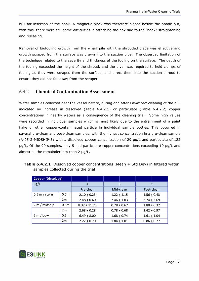
indicated no increase in dissolved (Table 6.4.2.1) or particulate (Table 6.4.2.2) copper
concentrations in nearby waters as a consequence of the cleaning trial. Some high values
were recorded in individual samples which is most likely due to the entrainment of a paint
flake or other copper-contaminated particle in individual sample bottles. This occurred in
several pre-clean and post-clean samples, with the highest concentration in a pre-clean sample
(A-05-2-MIDSHIP-5) with a dissolved copper concentration of 29 µg/L and particulate of 122
µg/L. Of the 90 samples, only 5 had particulate copper concentrations exceeding 10 µg/L and
almost all the remainder less than 2 µg/L.
Table 6.4.2.1 Dissolved copper concentrations (Mean + Std Dev) in filtered water samples collected during the trial
Copper (Dissolved)
µg/L A B C
Pre-‐clean Mid-‐clean Post-‐clean 0.5 m / stern 0.5m 2.10 + 0.23 1.22 + 1.15 1.56 + 0.43 2m 2.48 + 0.60 2.46 + 1.03 3.74 + 2.69 2 m / midship 0.5m 8.32 + 11.75 0.78 + 0.67 1.80 + 0.32 2m 2.68 + 0.28 0.78 + 0.68 2.42 + 0.97 5 m / bow 0.5m 6.49 + 8.00 1.68 + 0.74 1.61 + 1.04 2m 2.22 + 0.70 1.84 + 1.01 0.86 + 0.77
Franmarine In-Water Cleaning Trials
Page 33
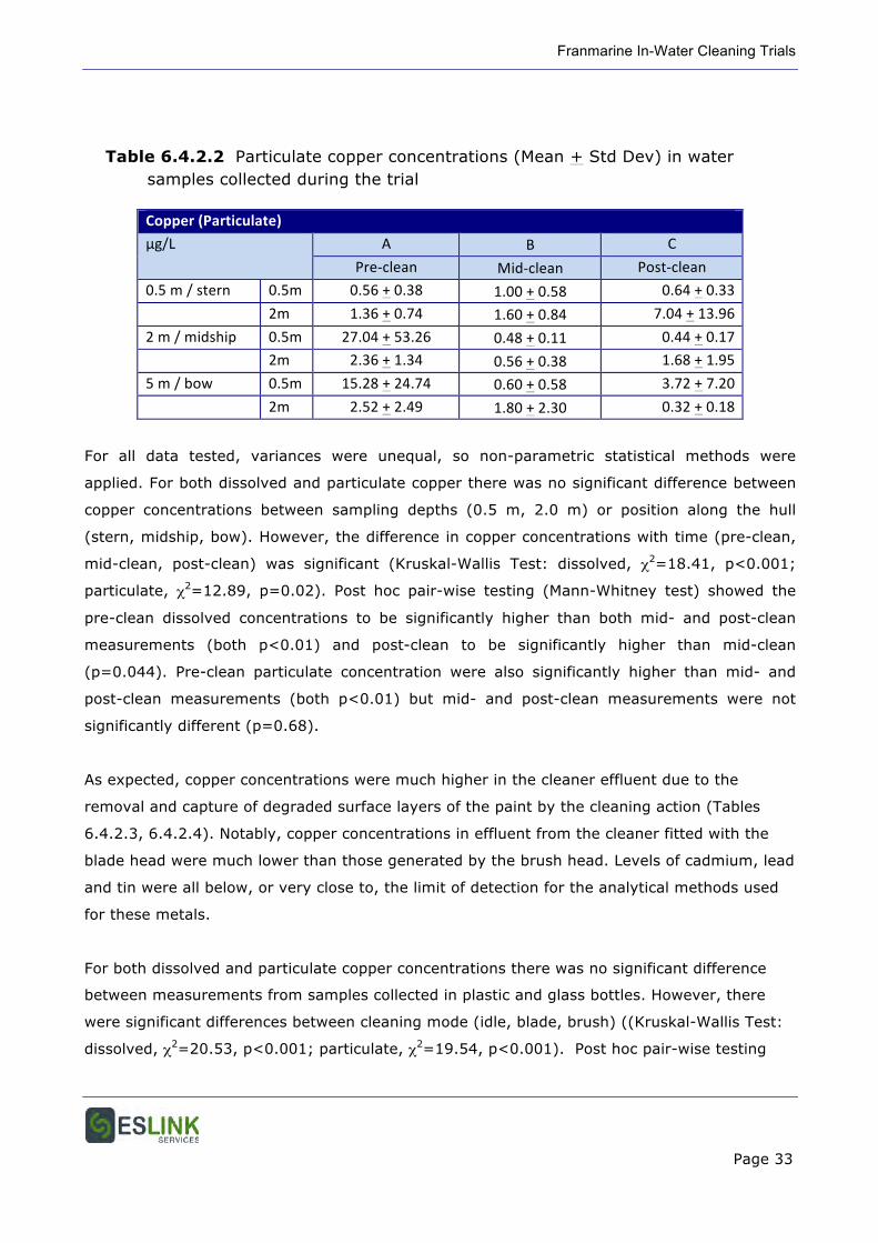
Table 6.4.2.2 Particulate copper concentrations (Mean + Std Dev) in water samples collected during the trial
Copper (Particulate)
µg/L A B C
Pre-‐clean Mid-‐clean Post-‐clean
0.5 m / stern 0.5m 0.56 + 0.38 1.00 + 0.58 0.64 + 0.33
2m 1.36 + 0.74 1.60 + 0.84 7.04 + 13.96
2 m / midship 0.5m 27.04 + 53.26 0.48 + 0.11 0.44 + 0.17
2m 2.36 + 1.34 0.56 + 0.38 1.68 + 1.95
5 m / bow 0.5m 15.28 + 24.74 0.60 + 0.58 3.72 + 7.20
2m 2.52 + 2.49 1.80 + 2.30 0.32 + 0.18
For all data tested, variances were unequal, so non-parametric statistical methods were
applied. For both dissolved and particulate copper there was no significant difference between
copper concentrations between sampling depths (0.5 m, 2.0 m) or position along the hull
(stern, midship, bow). However, the difference in copper concentrations with time (pre-clean,
mid-clean, post-clean) was significant (Kruskal-Wallis Test: dissolved, χ2=18.41, p<0.001;
particulate, χ2=12.89, p=0.02). Post hoc pair-wise testing (Mann-Whitney test) showed the
pre-clean dissolved concentrations to be significantly higher than both mid- and post-clean
measurements (both p<0.01) and post-clean to be significantly higher than mid-clean
(p=0.044). Pre-clean particulate concentration were also significantly higher than mid- and
post-clean measurements (both p<0.01) but mid- and post-clean measurements were not
significantly different (p=0.68).
As expected, copper concentrations were much higher in the cleaner effluent due to the
removal and capture of degraded surface layers of the paint by the cleaning action (Tables
6.4.2.3, 6.4.2.4). Notably, copper concentrations in effluent from the cleaner fitted with the
blade head were much lower than those generated by the brush head. Levels of cadmium, lead
and tin were all below, or very close to, the limit of detection for the analytical methods used
for these metals.
For both dissolved and particulate copper concentrations there was no significant difference
between measurements from samples collected in plastic and glass bottles. However, there
were significant differences between cleaning mode (idle, blade, brush) ((Kruskal-Wallis Test:
dissolved, χ2=20.53, p<0.001; particulate, χ2=19.54, p<0.001). Post hoc pair-wise testing
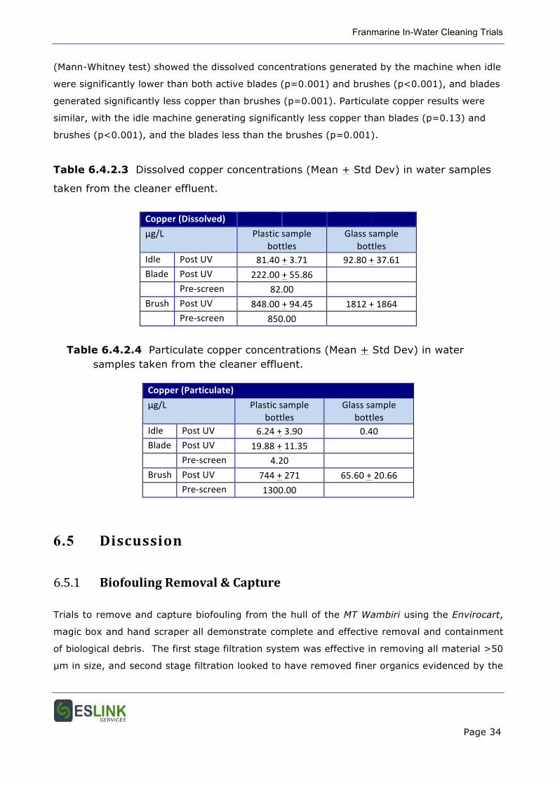
Franmarine In-Water Cleaning Trials
Page 34
(Mann-Whitney test) showed the dissolved concentrations generated by the machine when idle
were significantly lower than both active blades (p=0.001) and brushes (p<0.001), and blades
generated significantly less copper than brushes (p=0.001). Particulate copper results were
similar, with the idle machine generating significantly less copper than blades (p=0.13) and
brushes (p<0.001), and the blades less than the brushes (p=0.001).
Table 6.4.2.3 Dissolved copper concentrations (Mean + Std Dev) in water samples
taken from the cleaner effluent.
Copper (Dissolved)
µg/L Plastic sample bottles
Glass sample bottles
Idle Post UV 81.40 + 3.71 92.80 + 37.61 Blade Post UV 222.00 + 55.86 Pre-‐screen 82.00 Brush Post UV 848.00 + 94.45 1812 + 1864 Pre-‐screen 850.00
Table 6.4.2.4 Particulate copper concentrations (Mean + Std Dev) in water samples taken from the cleaner effluent.
Copper (Particulate)
µg/L Plastic sample bottles
Glass sample bottles
Idle Post UV 6.24 + 3.90 0.40 Blade Post UV 19.88 + 11.35 Pre-‐screen 4.20 Brush Post UV 744 + 271 65.60 + 20.66 Pre-‐screen 1300.00
6.5 Discussion
6.5.1 Biofouling Removal & Capture
Trials to remove and capture biofouling from the hull of the MT Wambiri using the Envirocart,
magic box and hand scraper all demonstrate complete and effective removal and containment
of biological debris. The first stage filtration system was effective in removing all material >50
µm in size, and second stage filtration looked to have removed finer organics evidenced by the
Franmarine In-Water Cleaning Trials
Page 35
absence of scum on foam in the discharge tank. Microscopic examination of filtered effluent
would be needed to confirm this.
Difficulties observed in both the initial securing of the magic box to the hull, and the capture of
heavy fouling when using the shrouded hand scraper could be easily rectified by minor design
modifications. For the box, the use of a rigid hook designed to marry with a magnetic hull
attachment (even if an interchangeable unit) should ease the attachment process and, for the
scraper, a larger shroud may be necessary for use in the removal of heavy biofouling growth.
6.5.2 Chemical Contamination Assessment
The acceptability of copper concentrations in the marine environment can be guided by acute
criteria provided by USEPA and ANZECC provides chronic guidelines from ANZECC based on
various levels of protection (80% to 99% of species).
Biocides removed and captured during in-water cleaning include both particulate and dissolved
contaminants from the antifouling coatings. The USEPA and ANZECC guidelines above are
considered most applicable to the dissolved component of the total biocide concentration.
Furthermore, copper speciation and bioavailability is known to greatly affect its toxicity for
aquatic organisms. For freshwater, the biotic ligand model has been developed to incorporate
the influence of copper speciation and of bioavailability in the presence of competing ions. This
model provides site-specific guidelines for different freshwater bodies. A marine-based biotic
ligand model has recently been developed for the USEPA, and the critical value for copper in
seawater has been determined to be 8.5 µg/L.
As a positive reflection on the magnitude of copper contamination in Fremantle Harbour,
dissolved copper concentrations measured around the vessel before, during and after the
cleaning trial were almost all below the ANZECC guideline for 90% protection (Table 6.5.2) and
the newly established USEPA critical value. However, the important result for the Envirocart
trial was that there was no indication of elevated copper concentrations in the water column
near the test vessel during or after the cleaning trial.
Franmarine In-Water Cleaning Trials
Page 36
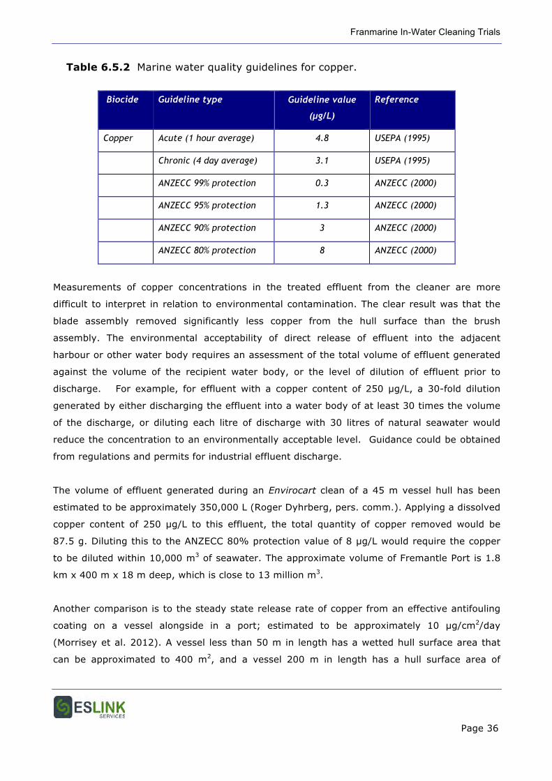
Table 6.5.2 Marine water quality guidelines for copper.
Biocide Guideline type Guideline value
(µg/L)
Reference
Copper Acute (1 hour average) 4.8 USEPA (1995)
Chronic (4 day average) 3.1 USEPA (1995)
ANZECC 99% protection 0.3 ANZECC (2000)
ANZECC 95% protection 1.3 ANZECC (2000)
ANZECC 90% protection 3 ANZECC (2000)
ANZECC 80% protection 8 ANZECC (2000)
Measurements of copper concentrations in the treated effluent from the cleaner are more
difficult to interpret in relation to environmental contamination. The clear result was that the
blade assembly removed significantly less copper from the hull surface than the brush
assembly. The environmental acceptability of direct release of effluent into the adjacent
harbour or other water body requires an assessment of the total volume of effluent generated
against the volume of the recipient water body, or the level of dilution of effluent prior to
discharge. For example, for effluent with a copper content of 250 µg/L, a 30-fold dilution
generated by either discharging the effluent into a water body of at least 30 times the volume
of the discharge, or diluting each litre of discharge with 30 litres of natural seawater would
reduce the concentration to an environmentally acceptable level. Guidance could be obtained
from regulations and permits for industrial effluent discharge.
The volume of effluent generated during an Envirocart clean of a 45 m vessel hull has been
estimated to be approximately 350,000 L (Roger Dyhrberg, pers. comm.). Applying a dissolved
copper content of 250 µg/L to this effluent, the total quantity of copper removed would be
87.5 g. Diluting this to the ANZECC 80% protection value of 8 µg/L would require the copper
to be diluted within 10,000 m3 of seawater. The approximate volume of Fremantle Port is 1.8
km x 400 m x 18 m deep, which is close to 13 million m3.
Another comparison is to the steady state release rate of copper from an effective antifouling
coating on a vessel alongside in a port; estimated to be approximately 10 µg/cm2/day
(Morrisey et al. 2012). A vessel less than 50 m in length has a wetted hull surface area that
can be approximated to 400 m2, and a vessel 200 m in length has a hull surface area of
Franmarine In-Water Cleaning Trials
Page 37
approximately 10,000 m2. The estimated daily release of copper from the small vessel is 40 g,
and from the large vessel, 1000 g. In the Morrisey et al. study, the copper released by in-
water cleaning of a vessel 50-100 m long to remove soft fouling was estimated to be
equivalent to that passively released in a day by two vessels 150-200 m in length.
When the trial on the Wambiri was conducted, the vehicle carrier Hoegh St Petersburg was
moored at the adjacent wharf. With a length between perpendiculars of 218 m, this vessel
would be releasing approximately 1000 g Cu/day, more than a magnitude greater than the
copper estimated to be generated by the Wambiri hull clean.
Franmarine In-Water Cleaning Trials
Page 38
Figure 6.1 Trial 4 test vessel: MT Wambiri
Figure 6.2 Hull surface prior to cleaning.
Figure 6.3 Hull surface prior to cleaning.
Franmarine In-Water Cleaning Trials
Page 39
Figure 6.4 Hull surface after cleaning with the Envirocart fitted with bladed discs.
Figure 6.5 Hull surface after cleaning with the Envirocart fitted with brushes.
Figure 6.6 CP anode after high pressure water cleaning inside the “magic box”.
Franmarine In-Water Cleaning Trials
Page 40
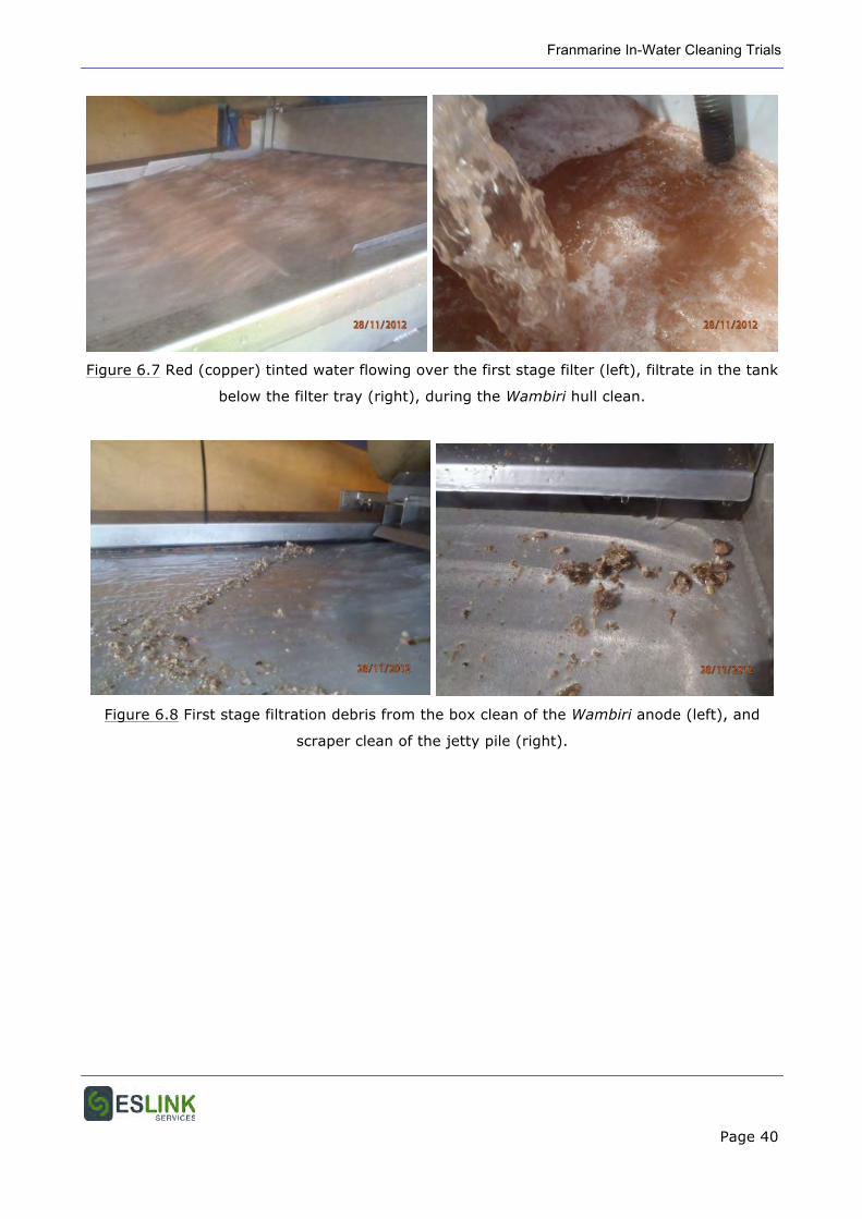
Figure 6.7 Red (copper) tinted water flowing over the first stage filter (left), filtrate in the tank
below the filter tray (right), during the Wambiri hull clean.
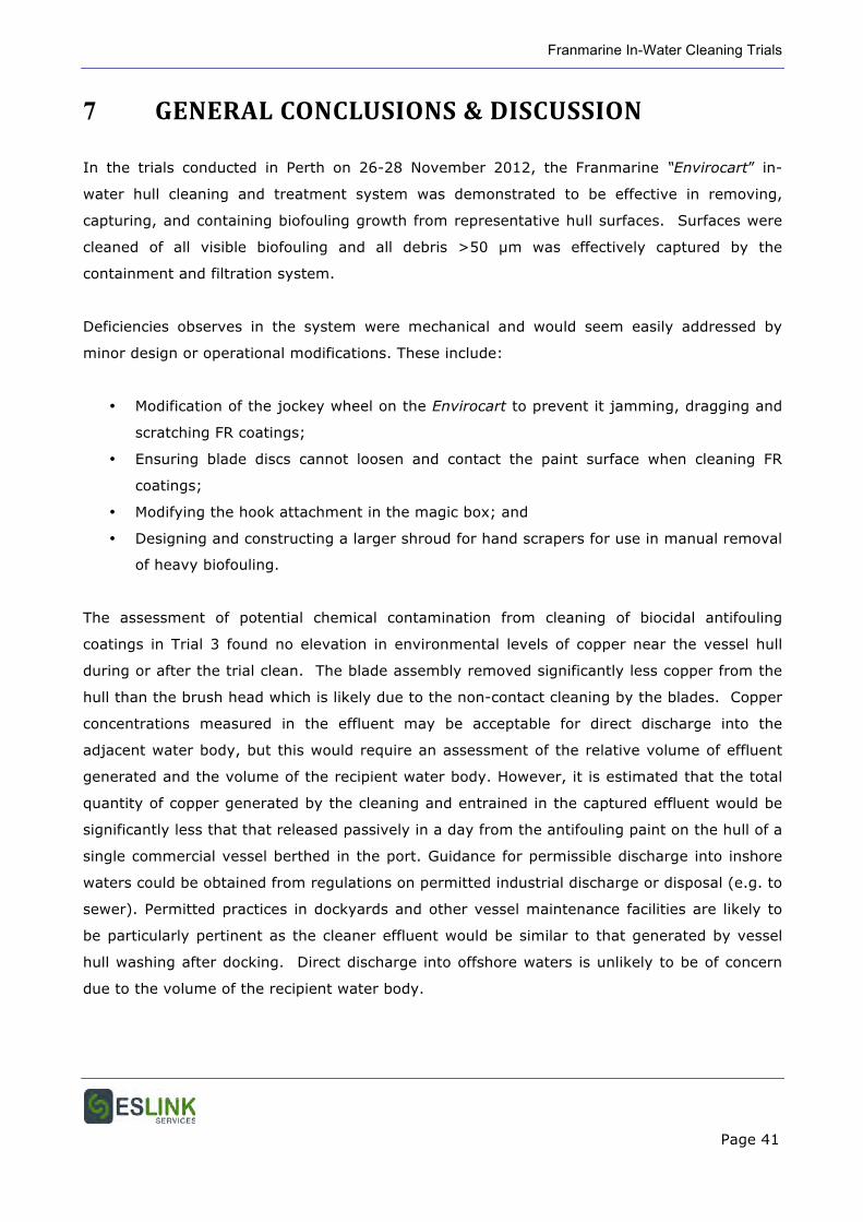
Figure 6.8 First stage filtration debris from the box clean of the Wambiri anode (left), and
scraper clean of the jetty pile (right).
Franmarine In-Water Cleaning Trials
Page 41
7 GENERAL CONCLUSIONS & DISCUSSION
In the trials conducted in Perth on 26-28 November 2012, the Franmarine “Envirocart” in-
water hull cleaning and treatment system was demonstrated to be effective in removing,
capturing, and containing biofouling growth from representative hull surfaces. Surfaces were
cleaned of all visible biofouling and all debris >50 µm was effectively captured by the
containment and filtration system.
Deficiencies observes in the system were mechanical and would seem easily addressed by
minor design or operational modifications. These include:
• Modification of the jockey wheel on the Envirocart to prevent it jamming, dragging and
scratching FR coatings;
• Ensuring blade discs cannot loosen and contact the paint surface when cleaning FR
coatings;
• Modifying the hook attachment in the magic box; and
• Designing and constructing a larger shroud for hand scrapers for use in manual removal
of heavy biofouling.
The assessment of potential chemical contamination from cleaning of biocidal antifouling
coatings in Trial 3 found no elevation in environmental levels of copper near the vessel hull
during or after the trial clean. The blade assembly removed significantly less copper from the
hull than the brush head which is likely due to the non-contact cleaning by the blades. Copper
concentrations measured in the effluent may be acceptable for direct discharge into the
adjacent water body, but this would require an assessment of the relative volume of effluent
generated and the volume of the recipient water body. However, it is estimated that the total
quantity of copper generated by the cleaning and entrained in the captured effluent would be
significantly less that that released passively in a day from the antifouling paint on the hull of a
single commercial vessel berthed in the port. Guidance for permissible discharge into inshore
waters could be obtained from regulations on permitted industrial discharge or disposal (e.g. to
sewer). Permitted practices in dockyards and other vessel maintenance facilities are likely to
be particularly pertinent as the cleaner effluent would be similar to that generated by vessel
hull washing after docking. Direct discharge into offshore waters is unlikely to be of concern
due to the volume of the recipient water body.
Franmarine In-Water Cleaning Trials
Page 42
Addressing relevant elements of the DoF requirement for the trial and system (Section 3):
[The system]
• is capable of safely and securely encapsulating and treating (killing and removing bio-
foul organisms in a timely manner) a range of vessels types and sizes:
o Demonstrated;
• Is suitable for 40m vessels in the trial and that can be scaled to accommodate larger
vessels (55 m long):
o Demonstrated;
• Is deployed in the Dampier region to service including but not be limited to, oil and gas
industry vessels:
o Is possible;
• Tests a range of chemical and/or alternate (e.g. anoxia, freshwater) treatments to
neutralise marine bio-fouling:
o Not completely relevant, but the system does UV treat effluent after filtration.
Viability studies on effluent would be necessary to prove this, but filtration to 10
µm in the second stage filtration would remove potential propagules;
• Includes a cost-benefit analysis that evaluates the efficacy and suitability
(environmental impact, cost, accessibility) of each treatment tested:
o Reported separately;
• Contains all treatment chemicals and bio-fouling organisms removed from vessel with
zero to minimal discharge and/or impact to the surrounding marine environment:
o Biological containment demonstrated; no treatment chemicals used in this
system; treated effluent contaminated by antifouling biocides can be contained
for disposal if assessed as unacceptable for direct discharge;
• Safely captures and removes all bio-fouling organisms and residue for analysis and safe
disposal:
o Demonstrated;
• Uses novel techniques such as digital video and/or sonar imaging to provide a record of
the extent of biofouling on each vessel:
o Conventional imaging techniques applied and adequate
• Includes methods that are capable of killing and removing bio-foulers from all areas on
a vessel including the hull and vessel bottom, plus niche areas such as propellers,
propeller shafts and sea chest grates:
o Demonstrated in part- hull surfaces were cleaned and the methods for cleaning
niches demonstrated, but only a limited number of specific niches were cleaned
in this and the previous Wambiri trial.
Franmarine In-Water Cleaning Trials
Page 43
• Allows the DoF, or their representative, to conduct in-situ research to evaluate the
efficacy of the system and treatment methods used to kill and capture marine bio-
fouling organisms (approximately within one month of development):
o Facilitated; and
• Includes practical considerations of using these technologies such as start-up and
running costs, accessibility and Occupational Health and Safety issues:
o Addressed.
Franmarine In-Water Cleaning Trials
Page 44
8 REFERENCES
ANZECC, 2000. Australian and New Zealand guidelines for fresh and marine water quality.
National Water Quality Management Strategy Paper No. 4, Australian and New Zealand
Environment and Conservation Council and Agriculture and Resource Management Council of
Australia and New Zealand, Canberra, Australia.
Floerl, O., Peacock, L., Seaward, K., Inglis, G., 2010. Review of biosecurity and contaminant
risks associated with in-water cleaning. Department of Agriculture, Fisheries and Forestry,
Australia.
Lloyd’s Register Group, 2012. Ballast water treatment technologies and current system
availability. September 2012. Lloyd’s Register Group Limited, London, UK.
Morrisey, D., Gadd, J., Page, M., Floerl, O., Woods, C., Lewis, J., Georgiades, E., 2012. In-
water cleaning of vessels. MPI Technical Paper (unpublished draft). Ministry of Primary
Industries, Wellington, New Zealand.
USEPA, 1995. Ambient water quality criteria-saltwater copper addendum (Draft), April 14.
Office of Water, Office of Science and Technology, United States Environmental Protection
Agency, Washington, DC