Embed Size (px)
Citation preview
REPORT 1390
INCOMPRESSIBLE FLUTTER CHARACTERISTICS OF REPRESENTATIVE AIRCRAFT WtNGS 1
By C. H. WILTS
SUMMARY
The prwnt report gives the resu-h%oj a dgtaikd study of theflutter charadmktim ~four reprawntu$iveaircrajlm“ngs. Thtistudy was md using the ele~”a-ana.tog computer at the Cali-fornia Imtitut.e of Technology. During the cour8e of thtiinvestigation ~“ght importunt paramet.em of each mung werevaried and, in addition, the e$ea% of mass, inertia, pitchingSpn”ng,and location of a CO?W8?UW&?d7nu88were inv~”gai.edfor alljour m“ngsand al severalsweepbackangles.
The introduction of thiareport discuss~ in general ternMttijluti characteristics of airp.kuw. The second section con-tain8 a A.ww-ssionof the electric-analogprincipl~ thd made astudy of thi8 magnitti fem”ble. The third section contuirwadiscussion of the amodynamic and structural appm”maiimmadejor a“mplif~”ngti$utter anulyti of a m“~. Thefourthsection @“vesinformation re.?utingto the errors introduced bythe jinitedi$erence approm”mationsto continm aeroelmticsystem. In addition, dtia are given pertaining to the jtutterchara&ristics of a wcept-”ng whui%nnel model, and theresults of computaiiww based on two assumptions regardingoxrod~amic forces on a wept mungare do ~“ven. Th-ejifthsection listi the physz”calchuracteristimof the four representa-tive aircra~ W“WSand the dxth seciion com!aim the compuiedjlutier characteristicsof thefour m“ngs.
INTRODUCI’ION
Flutter is a phenomenon which is observed in the transientor unforced response of an aerodynamic system. Mathe-hmtimlly speaking, it is observed in the solution of thehomogeneous” d.ithential equation describing the behaviorof an airplane in ilight through stiU nonturbulent air. Anairplane wing which is considered to be a continuous beam-Eke or platelike structure has an infinite number of degreesof freedom, and the characteristic equation which describesthe transient response has an ini@ite number of roots.Experience has shown that only the roots of lower magnitude(frequency) exhibit the problem of instability or flutter. Itis this fact which makes it possible to predict flutter using
‘ m analog computer, which represents only the lower fre-quency modes of the structure, or using a few normal modesin either digital or analog computation.
The exponents in the trimsientresponse of a linear systemare the roots of the characteristic equation. Since the char7acterietic equation involves red parametem, the roots arereal or occur as cemplex conjugate pairs. The latter roots
are the ones of interest here. The real part of a conjugatepair is the .reciprowd of the time constant in the transientresponse and the (positive) hqaginary part is the frequencyof oscillation. This is illustrated in figure 1. Mathematicaldescription of the transient term is
y=~le(u+f u)~+~*e(eto)t
or in terms of real functions
y=J4L4’ Cos(d+l#)
If the real part of the pair of roots u is negative the “tran-sient” dies out and the root is said to be stable. If the realpart is positive the transient grows exponentially untillimited by nordinearities or destruction, and the root is saidto flutter. The terminology is not strictly correct, but it iscommon practice to refer to the exponents of the transientresponse as flutter rcots since they are numerically equal tothe roots of the characteristic equation. Throughout thisreport such terminology will be used.
Damping of flutter rcots may be measured by two dimen-sionless numbers ~ and g, which differ from each other by rLfactor of 2. The former is generally used by control-stemengineers; the latter, by flutter analysts. They can be de-fined by the equation for the particular term in the transientrwponse given ed.ier
y=Ae’ cm (Ot+@)=Ae-r4 CCS[-J~&t+#]
~-1II
--+I
I
L
lmagrna~I
k!
Real
l?mwm I.—Transientresponseaorwpondingto rootsof ohmmteristioequation.
ISupxLWIMNAOATNS%0,‘TnmmprdbleFlnttaOhmdeiidu a!RePc6s@&IvaAIrcdtWIWE”byO.H,[email protected]
https://ntrs.nasa.gov/search.jsp?R=19930092369 2018-06-07T18:06:14+00:00Z

1386 REPORT 139&NATIONAL ADVISORY COMMTITEEFOR AERONAUTICS
I?lutter computations are usually centered around regioiswhere the value of g lies in the rmge. —0.2Q<0.2. ~such cases the factor ~ differs from unity by less thanO.S percent. For this reason it is customw-y to omit thisfactor in the trigonometric term giving the followingapproximation:
04~=Ae 2 Cos (U.t+i)
This practice will be followed in this report. For dampingwhich is small, an approximatee rule of thumb is that thedamping factor g is nearly equal to the per unit decrementper cycle divided by r. If percent decrement per cycle 6 isused, there results the convenient approximation ..
The flutter roots of an airplane are complex functions ofall geometrical, structural, and inertial properties of the air-fkame as well as of the airspeed and air density. With allother properties held constant, the lowest airspeed at whichthe flutter root exhibits neutral stability is called the flutterspeed. If g is plotted as a function of velocity, the absci&a(speed) at which the curve tit crosses the axis g=O is theflutter speed. In this study such curves were used to deter-mine the flutter speed, but such curves are used in thisreport only to illustrate the behavior of some unusual flutterroots. A tabulation of flutter speeds does not always given good picture of the flutter characteristics. An example isshown in figure 2, where the damping of two roots is show-n.One root becomes unstable at a speed of about 300 milesper hour and the other, at a speed of about 600 miles perhour. If a parameter variation increases the damping g ofboth roots by 0.03, one flutter speed is raised to 350 @esper hour, a 17-percent increase; the other is raised to 603miles per hour, a 0.5-percent increase. A further increasein g of 0.02 will raise the second flutter speed 0.4 percent to605 miles per hour, while the iirs.kxoot will now exhibit noflutter. It should be emphasized that even though a dtignspeed of, say, 500 miles per hour has been surpassed, thesystem may still be regarded ns unsatisfactory. A systemso close to flutter at a speed of 360 miles per hour mightactually flutter because of weight (fuel) variations or minordifferences in stiilness resulting from variations within themanufacturing tolerance. From the standpoint of this re-port all three of the sets of roots discussed above will be
-.2 /
-.1
go \ /
\: ‘ ——-1
‘\..2 \ w ,
0 200 400 600Velocity, mph
...FICJUEB2.—Variationof g’withvelocityfor typioalflutterroots.
regarded as having essentially the snme flutter chmacterls-tics even though they exhibit radically d&rent theoreticalflutter speeds. Emphasis is given to this point becnumremarks to be made later in this report may be misunders-tood without a clear conception of this viewpoint.
This investigation was conducted at the California Insti-tute of Technology under the sponsorship and with thofinancial assistance of the National Advisory Committee forAeronautic.
A, A,, Azz)”b,b.
()c?
“CL=dEEI
;1f.
f-QQJ
9hIJjk1M, fMl, M2,
mmcmfmm .mw,%
SYMBOLS
constants.half chordhalf chord at roothalf chord nt tipsymbolic representation of circulatory compo-
nent of lift force due to angle of nttncklift cceflicientwing station from root, in.Young’s modulus of elasticityequivalent beam flexural rigidity, (lb) (sq in,)experimental; used as subscriptflutter frequency, cpsnormal mode frequency of cantilevered mgino
and nacelle, cpsflutter frequency for continuous structureshear modulusequivalent beam torsional rigidity, (lb) (sq in.)
91#damping factor of a damped sinusoid,e ‘~ Cosdvertical deflection, positive down, in.moment of inertiaper unit length, lb secztorsional stiffnwsincrease in stMnes9,percentradius of gyration, in.Semispanof wingMa, M4, M5 twisting moment nbout elastic
mm per unit length of wing,positive nose up, lb
mass per unit length, lb see?/sqin.mass of concentrated massfuseh.ge mwstotal wing mnss, lb secl/in.total wing row-s outside of fuselagehmmed mass
P, P,, Pl, P3, P4- liftforce per unit length of wing, positivenose down, lb/in.
P ‘ Laplace transformation variable!lS dynamic pressure bnsed on normal component
of velocity, (1/2) PV%2,lb/sq in.t time, secw airstieam velocity, in./secnb flutter velocity of airplane with bare wingUf airstremnvelocity at which flutter occurs, iu,/secon component of airstream velocity perpendiculm
to el~tic axis, v ma A, in.lsecv~ reference velocity, in.lsecV- flutter velocity for continuous wingw distance measured along wingX. distance from midchord aft to elmtic nxis, in,
JNCOMPRESS~IJI I?LU’M’ER CILKRAC7TERISTICSOF REPREISDNTATITEAEtC!FLkFTWINGS 1387
xl distance from quarter chord aft to elastic axis,Xo+ (b/2), in.
Q distance from three-fourths chord forward toelastic axis, b —z,, in.
X3 distance from elastic axis aft to center ofmass, in.
V general variableAu cell size for finitediffwenc8 structureLY absolute pitch angle about elastic axis, positive
nose up, radians6 percent decrement per cycle1 per unit criticnl dampinge slope of elastic axis or roll about horizontal
axis normal to elastic axis, positive tip down,radians
A sweepback angle of elastic axis, degP air density, lb-see?/in.4T wing twisting gradient, bapwu real part of pair of rootsu angular frequency, rwliani+sec
undamped natural frequency, rdians/sec?’), (“”) derivatives with respect to time
ELECTRIC-ANALOGMETHODSOF J?LU’M’ERANALYSIS
The use of electrical analogs for the solution of aeroelasticproblems has been discussed in detail in reference 1. Thepurpose of the present section is to summarize the principlesbriefly. For purposes of flutter analysis the structuralsystem is assumed to be linear, and a linear electrical networkis constructed whose electrical behavior approximates thedynamic behavior of the linearized structure. For thispurpose, mpacitora are ordmsrily used to represent con-centrated or lumped inertia properties, inductors are usedto represent lumped flexibility properties, and transformersare used to represent the geometrical properties of thestructure (refs. 1 and 2). In such electrical analogs voltagesthroughout the network represent velocities in the structureand currents represent forces.. Electronic equipment is usedto produce currents which depend on voltages in the elec-trical system in the same manner in which aerodpamicforces depend upon the velocities of the airfoil.
The composite electrical structure cambe regarded as anelectrical model of the aircraft in the same manner that awind-tunnel model would be regarded as a structural model.The advantage of this approach lies in the relative ease withwhich one can alter the properties of the model, thus pw-forming flutter computations with great rapidity. It shouldbe emphasized that the normal modes of the structure arenot used as tools or elements in the analysis. The analysisconsists, in fact, in observing the behavior of an electricalmodel of an aircraft in flight.
That behavior which is most readily observed is the tran-sient response to a sudden disturbance. This method isthomfore similar to the testing technique which is ordinarilyused for wind-tunnel models. An advantage of the electricalmethod is that tuned pulses may be used so that separationof two or more nearly ~table or slightly unstable modes ofoscillation is more readily accomplished. Basic recordeddata consist of the logarithmic decrement of the responseand the frequency of oscillation. Flutter speed and fre-
quency for any [email protected] are ordinarily found by com-puting the damping g and frequency j for specific values oivelocity and interpolating to fid the frequency and speedat which g is zero.
APPROXIMATIONSFOR SIMPLIFYINGFLUTTERANALYSIS
STRUCNIIL4LREPRWENTATION
For dynamic analysis of airplane wings of large aspectratio, it is customary to treat the wing as a beamlike struc-ture in both vertical bending and torsion. It is usuallyassumed for simplici~ that w elastic axis exists. I?or anunswept wing this is a straight line which undergoes no ver-tical displacement when the wing is subjected to a puretorque parallel to this axis and along which no twisting gra-dient exists when verticil loads are applied anywhere alongthis line. For an unswept wing of conventional constzwctionthis simplification is usually quite accurate. For a sweptwing an elastic axis maybe defined as a stiaight line whichasaurnes a constarrt slope over its entire length when atwisting moment is applied parallel to this line and whichhas no twisting gradient when vertical loads are appliedanywhere along this line. For aspect ratios greater than 5or 6 and for conventional wing construction, a line can befound on the structure which satisfies this ddaition reason-ably well except near the root. It is not uncommon to findan equivalent elastic axis at about the 35-or 40-percent chord,a line located aft of the leading edge a distance equal to 35or 40 percent of the local chord.
The asanmptionof an elastic axis involves the tacit assumpt-ion that chordwise bending of the wing is negligible. Itfollows, then, that the motion of the wing at any spanwisecoordinate can be described by two coordinates, the vertical~placement of some point on the chord, cad the angle oftwist of the chord. II wing motion is described in terms ofvertical motion of the elastic axis and twisting motion aboutthis line, then these motions are not coupled through theaction of elastic forces in the wing except in the root regionfor a swept wing.
The root region of a swept wing is necessarily a relativelycomplicated structure. However, for aeroelastic problemsan eqnkdent simple structure can be found which is com-pletely satisfactory for wings of large aspect ratio. This canbe demonstrated by the following reasoning. The outersections of a wing exhibit detite beamlike properties, butin the region of the root considerable warping of the wingsurface must take place. The aerodynamic forces near theroot of the wing are therefore not adequately described bystrip theory (see discussion of strip theory under “Aero-dynamic Forces”). In ad&ion, the inertia effects of thissection are not readily computed. However, the effects ofthe aerodynamic forces on the root section are insignificantfor ordinary flutter computations. This has been demon-strated many times with the analog computer by removingthe aerodpmmic forces on the inboard cell of the finite-difference structure. The inertia forces are also insignificantcompared with the elastic forces transmitted by the rootsection; and it is therefore possible to replace this section forpurposes of analysis by a set of “influence coefficients”relating transmitted forces to displacement of an outer sec-
.
1388 REPORT 139ENA’!XONMJ ADVIBORY COMMITTEE
tion of the wing relative to the fuselage. It has been foundthat in some cases these influence coefficients resemble co-efficients for a simple beam extending straight into thefuselage and attaching there in’some simple way. The wingstructural axis then consists of a short section which maybeperpendicular to the fuselage center line and which is simplyattached to a swept back elastic axis which extends to thewing tip.
Methods for determining the equivalent structure areoutside the scope of this report. Since this structure varies
P_424”lo6”~
L
(0)
.
/“
.(b)
LI—- _1
—.j-
1—1-- -
II
-r2&”
3
+; -:’$’1””t
r[—.So” i“.,4- ~ ~ i~,,200” - I I
1-
1
—-
(c) ‘JS45°
(a) Fighter L (b) Fighter B. (c) Bomber A. (d) Bomber B.FKIURFI3.—Plan forms and cell ditilon of baaioairplane.
greatly with
,
FOR AERONAUTICS
the particular wing construction used, it wmnecessary to choose a simple though typical root structure forthis study. The structure chosen is illustrated in figure 3where the elastic axes are shown by broken lines. The breakin the elastic axis is assumed to be at the edge of the fuselage,and the axis inside the fuselage is assumed to be straight andperpendicular to the airplane center line. The wing isassumed to be pinned at the side of the fuselage. Conse-quently, all twisting moment is removed at this point andit is not necessary to make any assumptions regarding twist-ing rigidi~ inside the fuselage. Bending rigidity inside thefuselage is, however, important for symmetric motion,During the past 6 years extensive flutter computations hovebeen made with the electric-analog computer for commercialand military aircraft as well as for wind-tunnel modelsincluding those described in references 3 and 4. In all casesinvestigated, it has been found that relatively large varia-tions in root conditions have a negligible effect on the fluttercharacteristics (in the sense described in the Introduction).Observed changes in damping were usually in the range0<] Ag[<0.05j which has very small effect on flutter speedunless the curve of g against velocity is very flat, ‘near zerovalues of g. Needless to say, both symmetric and anti-symmetric motion of the airplane must be permitted sincothe flutter characteristics for the two types of motion maybe quite different.
Fuselage stitluws rmd iner@a properties usually havevalues such that an asswgption of a rigid fuselage for sym-metric motion alters the flutter characteristic little. Norfighter planes the error introduced is negligible. For lmgebombers the change in flutter speed maybe appreciable, butit does not alter the trends to be observed upon variation ofwing properties. It has therefore been assumed in thisstudy that the airplane fuselage is &ld. Tail-surfaceflexibility does not significantly affect wing flutter problems,A rigid tail surface with snflicient area to provide satisfactorystatic stability has therefore been assumed.
AERODYNAMICFOR(7RS
For all the flutter computations given in this report, thoaerodynamic forces have been simplified by two hnportantassumptions:
(1) The air flow is incompressible.(2) If the airfoil is divided into strips perpendicular to
the elastic axis, then the forces on each strip can be com-puted as a function of the normal component of the &stream velocity and the motion of that strip can be computedindependently of the motion of adjacent strips,
The first assumption is not required by analog methods ingeneral, but its use greatly increases the rapidity with \vhichdata can be obtained. -Since the purpose of tha study is notto obtain specific accurate flutter speeds but to study trendsin flutter characteristics, this assumption doea not seemunreasonable. With regard to the use of strip theory twoassumptions are often found in the literature. In using the“airstream method” the wind is divided into strips parallelto the airstwmn, and the forces and moments on each stripare computed as though the wing were not swept and theair flow about the section were a two-dimensional inco)n-pr’esible flow. The aerodynamic coefficients may be taken
INCOMPRESSIBLEFLVI?J!J3RCEXRMTERISTICS OF REPIUMDNTATIVEAIRCRAFT WINGS 1389
to be the same as those for rmunswept wing or may be modi-fied by a factor cos A. In applying the “normakomponentmethod,” the wing is divided into strips perpendicular tothe elastic axis. The aerodynamic forces and moments arecomputed as though the effective air velocity were thenormal component v cos A, and the forces depend only onthe motion of the individual strip and not upon the motionof adjacent strips (except that some small terms may beincluded which me proportional to the twisting gradient andtherefore dependent upon the motion of the nearest strips).A critical discussion of the two alternatives is given inreference 5. This reference recommends use of the normal-component method.& Before adopting the second assumption, an effort wasmade to iind some correlation with experimental results.Reference 3 contains experimental flutter speeds for a wind-tunnel model wing with sweepback angle equal to about 35°.This angle is sufficient to give an appreciable difference inresults obtained with the various assumptions mentionedabove. The section entitled “Finite-D~erence Errors” inthe prewmtreport contains the resultsof computations whichshow that the normal-component method gives results whichnre as satisfactory as those given by any other method used.
Equations for determining the aerodynunic forces by thismethod are given in reference 5. In the equations giventhere, several terms are found whose theoretical justificationis not well established. These terms (grouped in specialbrackets on p. 16 of ref. 5) were found to have negligibleeffect on sample flutter computations. It seems reasonable,therefore, to omit these terms from computations invol~edin the present trend study. With these omisiona and withobvious changes to conform to the symbols and notationused in the present report, the equations are:
P=P,+P,+P,
fi.=M’l+M*+M3 +M4
( )[P,=–27r(q~ (2b)c ~ #+(a+o tan A)+5 (&+o tan A)]a
P2=–27r(qJ (:) (a)
P3=–7pb’(&zo4
M,= –27r(qJ (:) (a)
“l=-”pb’[(:+’~)a-’~l“’=2”(’J’b2’P(%)~(?)(-5’+~”)+
br+?-(%iilt’n’The terms are grouped in the order shown for convenience inestablishing analog circuits. The last term in P, is notfound in the corresponding equation of reference 5. This
term is ramoved (mathematically) by insertion of an equalbut opposite term in P4 and a similar term in A&It is added to P, here because the circuits which generate theterm a+o tan A also provide the term (zJvJ (&+d tan A),the lasit part of which is not found in reference 5. As ispointed out below, this term has a negligible effect so thatits inclusion is of no importance, but it is indicated in theexprwaion for PI for the sake of completeness.. It should beemphasized that the dynamic pressureq=is based on on,whereonis the velocity component normal to the elastic axis. Thecoordinates a and o are both measured in elastic-axis coordi-nates. The symbohm C(@@J is used to represent theTheodorsen or Wagner function. A short discussion of theinterpretation of this symbolic representation can be foundin reference 6.
All terms found above can be represented by simpleanalog circuits with the exception of P4 and M5. Examina-tion of equations 6 and 7 of reference 5 shows that each termin P4 and ills is-similar to (if not equal to) a term found inthe special brackets. Since the latter terms have beenomitted, there seems to be no logical reason for retainingP4 and Mb. Inasmuch as their inclusion greatly complicatesthe analog circuits, these terms were also omitted.
In addition to the fi.nite-difference approximations andthose contained in the assumptions of incompressible flowand strip theory, three other aerodynamic approximationsshould be mentioned. The first of these is the failure tomodify aerodynamic forces at the wing tip. The delay in thegrowth of lift forces, as dem.ribedby the Wagger or Theodor-sen, functions for two-dimensional flow; cannot apply nearthe tip. Indeed, both the delay in lift and the magnitudeof the lift must go to zero at the tip. The extent of the errorintrodumd depends upon the importance of tip forces influtter computations. Insofar as their location is concerned,these force-sare quite important, but, because of wing taper,the maggtude of the total force per unit length diminkhesnear the tip. Since wings of considerable taper are involvedin this investigation, it is to be expected that the error willbe relatively small. The second approximation is failure tocompute aerodparnic.forces properly at the root of a swept -wing. As stated earlier, the error introduced by this approxi-mation is negligible since the aerodynamic force for a largesection of the wing root can be omitted entirely without anappreciable change in flutter speed. The third approfia-tion is introduced by the necessity of computing the Wagnerfunction (or the Theodorsen function) electrically. Thisfunction is computed using networks shown in reference 1with an error no greatar than 2 percent over the frequencyrange or time interred of interwt.
mE-DIFFERENCE ERRORS
It is the purpose of this section to summmize work whichwas carried out at the Analysis Laboratory of the CaliforniaInstitute of Technology to determine i3.nite-dMerenceerrorsin flutter computations for severil specfic structures.
FINITE-DII’FERENCESTRUCTURES
No practical methods have been devised for representinggeneral continuous structure9 with continuous electricalsystems. The electric-sm,log computer utilizes lumped elec-
1390 REPORT 139&NA1’IONAL ADVISORY COMMTIT’EEFOR AERONAUTICS
trical elements which can, in principle, be used only to con-struct analogs for lumped mechanical systems. However,as pointed out in references 1 and 2, it is possible to repre-sent the dynamic characteristics of beamlike structures bya lumped structure based upon iinite-dil%mnce approxima-tions to prurtialdifferential equations. It is convenient tocall this lumped system a fite-diilerence structure, whetherit is a mechtmical model or an electrical analog. Thesereferences outline the process by which inertia and stifh.wssproperties and aerodynamic forces are averaged or replacedby single concentrated inertias, springs, or forces in theiinite-diflerenm stiucture.
It should be remarked, at this point, that the assumptionof a finite-diilwence stmc@re insures a finite number offlutter roots or exponential functions in the transient re-sponse, whereas the continuous structure has, in principle,an infinite number. Since the higher frequency roots havehigh damping, only the lower frequency roots are of interest.Two or three of these may, however, show essentially zerodamping simultaneously at a given velocity, and it is some-times necessary to determine the characteristics of severalflutter roots. There is obviously a 10WWlimit to the numberof cells that must be used to obtain satisfactory accuracy,sinca tmchcell adds roughly two roots to the system.
There is little information in the literature which pertainsto the accuracy with which such structures represent thecontinuous system. Reference 7 gives data for static-deflection and normal-mode characteristics of certain iinite-diilerence structures but no information about accuracy offlutter computations.
Using equations for aerodynamic forces based on two-dimensional strip theory and linear incompressible fluid flow,several “exact solutions” have been obtained for flutterproblems. Some of these are found in references 8 and 9.These solutions are exact in the sense that no further physicalor mathematical simplifications are involved and the onlyerrors are introduced by round-off errors in evaluating tmms-cendental functions and infinite series. Solution of thesesame problems by use of iinite-difference approximations topartial differential equations provides the most practical wayof estimating fl.nite-differenceerrors for other configurationsfor which exact solutions are not obtainable. It is true that,in all cases mentioned above, the airfoil has been assumed tohave uniform spamvise propw-tiesand that in most practicalcases the airfoil has a signitlcant taper. On the other hand,reference 7 contains a study of the iinite-di.flerenceerrors inthe deflection characteristics and normal-mode properties ofboth uniform and tapered beams. This study showed nounusual ditlerences in these properties, and so it is assumedthat the results obtained for flutter of uniform airfoils aretypical of r~ults that would be obtained for flutter of taperedairfoils.
UNIFORBfAIRPOILWITHPINNKDENDS
A uniform beam with pinned ends will support oDly sinu-soidal modes in both bending and torsion. Flutter modesare also of sinusoidal shape and it is therefore possible toreduce the flutter problem to an eigenvalue problem whichcan be solved with a high degree of numerical accuracy.The finite-difference analoga for a pinned-pinned beam like-
TABLE I.—PHYSICAL CHARACTERISTICS OFPINNED AIRFOIL
kmgth, ire---------------------------------------Half chord, b, h----------------------------------iMasaper unit length, m, lb .w#/aq in._--------------Inertia per unit length, 1, lb semi-------------------Bending rigidity, EI, lb ti.z------------------------Torsional rigidity, (7J,lb ti-------------------------XI, in---------------------------------------------q, ti --------------------------------------------Air density, p, lb seG/b -----------------------------
A PINNED-
28848
0.010365.170
L 412X 1096. 87X108
9+6–0, 6
0. 0846x 10-0
wise will support only sinusoidal modes. It is possibletherefore to get exact solutions for the iinite-diilorenceapproximations to the continuous airfoil.
The airfoil chosen for this analysis is described in tablo I.For the continuous wing, the flutter speed and frequencywere found to be VP692 miles per hour and-f-12.72 cyclesper second, respectively. Analysis of the fin.ite-ditlerenco‘structure was carried out using eight-, four-, and two-cdlchisions between the pinned ends. Results are given intable II and figure 4. For this particular case it is necessaryto use more than four cells if flutter speed is to be obtainedwith less than 2-percent error. By use of symmetry condi-tions at the center of the beam it is necessruy to use onlyhalf this number of cells with an electric-analog computer.Thus, use of two analog cells gives a theoretical error ofabout 2.2 percent, and use of four analog cells gives an errorof oDly 0.6 percent.
h////// I
v. 41/ 96”
////
~ /1/
I /& /
/Vm / )
AfJ /———fm /
,
// //
I ‘.////
iidasFIGURE4.-Finite-dMerence flutter-speed errors of pinned-pinned
beam.
~COMPRESSDHJE FLDIM’DR CRAR4CTERISTICS OF REPRESENTATIVE AJRCRAIT WNGS 1391
and flutter frequency were computed for seven masslocations,data for which arereproduced in table IV. Since the locationof a concentrated mass may be important in flutter analysis,and since all points on a finitedifhmnce beam are notequally suitable as an attachment point for a concentratedmass, it was believed that a comparison of the above datawith iinite-clifTerencesolutions was quite important. Un-fortunately, similar accurate solutions for a fiteditlerencestructure are not readily obtained, so it was necessary to usethe electric-analog computer to obtain these solutions. The
TABLE11.—COMPUTEDFLUTTERSPEEDAND FREQUENCYOF FINITE-DIFFERENCE PINNED-PINNED AIRFOIL
Nuuer ff,Cps
Vf,mph
692688077644
12.712.612.311.0
0.008.032.134
0.006.022.069
m
842
I rewdtiw comrwrison therefore contains both finite-difference-.and analog-computer errors. I?revious work has indicatedthat the latter are probably not greater than 1 percent if theTheodomen function is represented accurately.
In this analysis two slightly different beam analogs wereused. In both, the beamlike properties were represented bya system of levers (transformers), but in o~e group the lumpedforces were applied at the junctions of the levers and in thesecond group the forces were applied at the midpoints of the“levers. The analog of the second group was once thoughtto give a better approximation since it rwmbles the Russellbeam analog discussed in reference 7. Recent investigationhas shown that this belief is without foundation, and thesecond analog is now preferred only as a matter of conven-ience for esveptback wings since it provides the wing slope”directly at the force stations where it is needed for computa-tion of aerodynamic forces. In both cases the cantilevercondition at the root was provided by a half cell at the root,and the forces nearest the tip were applied one-half cell fromthe tip. Thus the first group involved an integral number ofcells, and the second group involved a half integgal (integerplus one-half) number of cells. Five cases were investi-gated; 2, 24, 4, %, and 6 cells. Since it was shown in theprevious section that less than 4 cells was of no interest forpresent purposes, only the results of 4, 54, and 6 cells arepresented in this report.
UNIFORMCANTILEVERWINGWITHCONCENTRATEDMASS
Analvticrd determination of the flutter meed of a cantilever.wing is much more difEcuIt than that for ~ beam with pinnedends, However, other investigators have obtained accuratenumerical solutions for a few- conjurations. The mostimportant of these is described in reference 9. This case isof importance for two reasons: It involves several spanwisepositions of a large eccentic concentrated mass which greatlyaffects the flutter speed; and for some positions at least twocompletely different flutter roots can be found.
Table III presents the physical characteristic of the airfoilanalyzed in reference 9. In this reference, the flutter speed
TABLE 111.—PHYSIUALCHARACTERISTICSOF UNIFORMCANTILEVER~NG
HaIfchord,b, in----------------------------------- 4Span, 1, in----------------------------------------- 4shfruwper unit lengtn, m, lb se&/sq in---------------- L 377X10+Pitching inertiaper unit length, lb seo ~-------------- a Oox 10-4Fhmuralrfgidity, EI, (lb) (sq in.)------------------- 1.407X10⁵Torsionalrigidity, (7J,(lb) (sq ti.)------------__-_-- O.692X 106Elastic-axisposition, z., ire----+ ------------------- –o. 504Contw-of-mms position, %, in----------------------- O.156Mom of concentrated mass, me lb se&/in----------- 3. 23X1O+Pitch inofil~ of concentrated mass, lb se&/in_______ 0.1636center of mass of concentrated mass, (~. in--------- –3. 274Air density, p, lb se&/in.4--------------------------- L 165X10_7
TABLE IV.—THEORETICAL AND EXPERIMENTAL FLUTTER CHARAGTERISTICS OF CANTILEVER WING WITH CONCENTRATED MASS
@3atataken frvmrefarmcw9and11]
Calculated EsperimimtalIhlas lo-
cntion~per umt
spanff,Cps
ff,Cps
Vf,mph
w>per unit,
P)
Vf,mph
w,per unit
(-)
0.400------
.397------------
.4ss
.631
.481
.442------
.360
52119.117.4 -16.315.5
b 16. 3-26.8(d)
(d)
2L 82L 62L 4
0.167.229.292.333.354.625.938.959.979
1.000
227------
226------------
2770359
273251
------205
25.27------
19.23------------2s. 0430.6825.6724.87
------23.60
22s221221233256260
-----261251231218
0.401. 3ss. 3ss.410.451.458
------.459442
.407
.334
I.1.0 w unitveldty Is l@ tnko or E@ mphbThkexp?rlmentalwrd ~ to showmarly simultaneousdivergmm andflutterat twofreqnenclescCahmhted divergems qmd ISabut Z7Qmph. However,aflutta @ c-anSHUb raldatd nmthenmtidy.
G2UJf174&90

.- ——-—- —..-.—... ...— .-.
1392 REPORT 139&NATIONAL ADVISORY COMMITTEE FOR AERONAUTICS
In view of the simplicity of the flutter curves shown inreference 9, it was expected that data would be taken atonly a few spanwise maw locations. However, it was soonfound that the flutter characteristics were much more com-plicated than anticipated, and data were taken at 24 masslocations in the 6-cell case. The flutter characteristics ofthe wing with variable location of the concentrated massare sketched in figure 5 (a). As the concentrated mass ismoved outward from the root, the flutter speed drops slightly.At a distance about 16 percent of the-total span from theroot a mum is reached, and beyond the 25-percent posi- -tion the flutter speed rises very rapidly. At the 30-percentposition the flutter speed for this root has become equal tothe flutter speed of a completely dilferent root. The flutterspeed for this second root drops with increasing spanwiseposition of the mass making it impossible to determine withthe analog mmputer the speed for the origiral root bpyondthe 30-percent position. The flutter speed for the secondroot reaches a minimum with the mass at the 45-percentposition, then rises to a very high value as the mass is movedtoward the 75-percent position. A flutter mot which isprobably the second is observed for mass positions near thetip, the lowest flutter speed occurring with mass at the tip. I
It yws also observed that divergence of the wing occurredwhenever the flutter speed exceeded about 5,000 bohes pmsecond. Because of divergence, it w-asnot possible to meaa-ure with accuracy flutter speeds which exceeded divmgeRcospeed by more than about 50 percent. As a result, fluttmspeeds with mass near the 76-percent span could not bemeasured.
The flutter characteristics for the 4-, 64-, and 6-cell struc-tur~ are shown in table V and figure 5 (b). Data for theseven positions analyzed in reference 9 are also plottod inthe figure. Inspection of these curves shows that many moroaccurate numerical solutions are required to determine tlmfinite-difference errors for all mass positions. In spito ofthe inadequate numerical data, an attempt was made to drawa smooth curve through the known points taken from refer-ence 9. In doing this the 54- and 6-cell analog data weroused as a guide in determiningg the shape of the curve. Thiscurve, shown in figure 5(a), has already been discussecl. Itis realized that a significant error of aa much as 2 or 3 pm-cent may esist in this curve for some mass positions, but therowas no other method for obtaining estimated errore for thofinite-difference structures. With the understanding thatthe comparison data may be in error in some regions, figmw 6
I I I I -1-d I I I I0
—.—,
o Theoretiwl _____ ,
10n Windtunnel o Theoretical
.7
/ I \
/51’ I
/
/ ,,#-- Divergence S@ed
,1 ,. FA11. .’ll!II I !
\ / ! i ‘k\. /’, ,. ,
In--l I I lit I III\b
/> ‘ &l+
(o).30 .5 Lo
Sponwise position of mass..-
(a) Themetioal and wind-tunnelflutter characteristioe.(b) Flutter oharacterieticsof linite-differenceanalog.
FIGURE 5.—Flutter characterietioa of uniform cantilever wing with cowentrated maw.

INCOdl?RESSHILE FLTJ’I’PDRCHARAC$’IT3RISTICSOF REPRESENTATIVE AJRCRAJ!TWINGS 1393
TABLE V.—FLUTTER CHARACTERISTICS OF FINITE-DIFFERENCE ANALOG OF U’NJJ?ORMCANTILEVERWING
“WY’””” ‘“ ‘Ph c’)of, per unit ff, w
4 cell
o 224 0.394 23.9126 212 .373 ----
:150 213 .374 ----.225 225 .396 la 9.250 241 .4% la 1.275 275 .484 ----.325 269 .473 27.7350 268 .454 27.2
:376 246 .431 26.3.500 273 .480 27.6.600 297 .522 2a2
626 308 .633 ‘2$.4:660 376 .661 3L 4.876 327 .676 26.7
960 237 .417 2401:000 197 .346 224
5J4 cell
o 223 0.392 23.8, 182 218 .383 20.3
!236 227 .399 I& 6:264 236 . 41s 17.8
273 249 .439 17.3:291 296 .620 2&5.309 289 .508 28.0. 32a 284 .600 %3.364 274 .482 27.9.464 244 .430 27.2.546 2a4 .600 28.3.600 313 .560 29.7.636 333 .686 30.7
866 377 .664 29.4:909 306 .637 27. (1.946 268 .464 25.6 ~
L 000 212 .373 23.9
6 cell
o 228 0.401 23.7.083 223 .393 23.3
167 219 .386 20.8:217 226 .398 18.7.250 239 .420 la o.267 266 .448 17.1
284 286 .604 16.7:317 296 .621 28.2.367 270 .476 27.6. 417 252 .443 26.8.450 268 .464 27.2’.600 266 .468 27.6.660 277 .487 27.8.683 232 .496 28.2.600 306 .639 28.9.616 334 .588 30.1
667 -477 =.840 ----:868 3-49 .614 2&4.333 319 .562 27.4.917 276 .436 26.3.960 242 .426 26.1.966 226 .398 246.984 213 .376 24.2
L 000 201 .353 23.6
●b@sspositlonlspwunStqmn measnrcdfmmrwtb1.0per smlt vdmky-b&3 mph.
10 I
5+ Cells
o / “1 /\ / ~
\
-lo
Spom& position of MOSS
l?muan 6.—Flutter+peed errors of finite-differenceanalog of uniformcantileverwing with concentmted maw.
ma prepared shotig the percentage error in flutter speedfor the vtious analogs as functions of the mass location.l?or 5+ and 6-cell structures the average errors are about 2percent. It can be readily seen that, although a 4-cellanalog gives yery satisfactory results for the bare wing (massposition O), it is necwary to use more than 4 cells if errorsless than 5 parcent are required at other mass locations. Afurther discumion of this investigation will be found inreference 10.
As a result of this analy&, it was decided that all fluttercomputations made in this trend study would be made using6* cells to represent on-half of the airplane wing.
EXP~TAL CORRELATION
Wind-tunnel tests have been made of many model struc-tures. It is diflicult, however, to find unclassified data inwhich the structure is completely and accurately described.In the course of this investigation, two cases were found inwhich a correlation between experimental and commtedcharacteristics could be attempted. The first of these is theuniform unswept, cantilever wing discussed in the precedingsection. The flutter speed and freqqency observed in awind tunnel are reported in reference 9 and a companionreport, reference 11. These data are summmized in tableIVj which also contains the computed values of reference 9.A better understanding of the correlation is obtained if theexperimental data are plotted with the aaaumed analyticsolution. Figure 5 (a) shows such a compm-ison. The corre-lation for this case seems unusually good.

1394 REPORT 139&NATIONAL ADVISORY COMM17M’EE FOR AERONAUTICS
FLUTTER SPEED OF A SWEPT-WING MODEL
The second case for which correlation with experiment ispossible is found in reference 3. This reference gives resultsof wind-tunnel tests to determine the flutter speed of a modelwing with sweepback angle equal to 34.5°. This wing hadtwo concentrated masses attached at approximately the 30-a.ndSO-percentspan positions. In an effort to compare theairatream and normal-component aerodynamics for fluttercomputations, an electrical analog was consh-uc~d for thiswing. I?or any sweepback angle it is to be expected that thetwo methods will give flutter speeds d&ring by a factor ofapproximately (COSA)ti, unless the aerodyntic coefficientsare modified by the factor cos A in the airstream method, inwhich case the hvo methods should give similarresults. Theprincipal difficulty encountered was determination of theproperties of the concentrated masses on the wing, sincereference 3 does not give complete information about thesemmses and their geometrical location. The best data thatcould be deduced from this report are given in table VI.Since the masses are dined with the airstreambut are repre-sented in elastic-rmiscoordinates, a product of inertia be-tween roll and pitch exists. Since no such information wasavailable, the product of inertia was omitted from computa-tions, and the rolling inertia about a chord line was assumedto be one-half as large as the pitching inertia about theelastic axis. It is believed that these approximations andsimplificationswill affect the results by less than 1 percent.
A comparison of observed and computed characteristics isgiven in table WI. The first three normal-mode frequenciesshow satisfactory agreement, with differences of 1, 5, and 3percent, respectively. The flutter speed computed witheither representation of aerodynamic forces is lower than thewind-tunnel value. Ii the case of the airstream method,the discrepancy is 19 percent, or, if the aerod~amic coef6ci-ent.sare modiiied, 11 percent. Using the normal-componentmethod, the discrepancy is 12 percent. Flutter frequency isin error about 20 percent in all cases. Although the observeddifleremes are relatively large in all cases, it is concludedthat the normal-component method recommended in refer-ence 5 is satisfactory for this model.
CHARACTERISTICSOF FOUR REPRESENTATIVEAIRCRAFT
Plan forms and stilhwss and inertia data were chosen aftersurveying the various fighter, bomber, and transport planesdeveloped in recent years. I?our representative airplaneswere chosen, two fighters and two kirge bombers. Smallerattack bombers and transports were not included Jecauseof lack of time. The airplanes chosen are not similar in allrespects to any particular set of four airplanes, but they dohave stillness and inertia properties which resemble fourspecific aircraft. I?lan form, sweepback angle, elastic-axislocation, and ccmcentrated-mass locations were, however,chosen more arbitra-fiy so that this report could remainunclaskiied. The four basic plan forms are shown in figure 3.The basic fighter A has a bare unswept wing with span ofabout 500 inches, taper ratio of 2.0, and aspect ratio 6. Thebasic fighter B has a wing sweepback angle of 30°, a spanof about 400 inches, and a taper ratio of 2.o. The two bticwings have the same length measured along the elastic axis
TABLEVI.-PHYSICAL CHARACTERISTICSOFSIVEPTBACKWING lVITH CONCENTRATEDMASS
~t9 bksnfrom rekenm 3;momdetailed informationwar bofound h ttdsrofercrm% Mossof wing L9for portion outlxm-d Orrwt rdmjnt. DoQ for COU~bti ~ wo nOtgiw?mexplidtly fn rokonm 3 and must b mgordul as only approstnmto,]
wing 13haracta’istics:
“Span, ir e- —----------------------------------- 4s. 3bl?oot half chord, bn h--------------------------- 52bTip half chord, b=, h---------------------------- 2.36Wing total mwj, ~, lb se&/in._------------.----- O.00784Tunnel fluid density, p, lb se@/ti.l--------..------.. 3.40X 10⁻⁷Sweepback angle, A, d%------------------------- 346
Concentrated-mass characteristics: OuttmrdMae+ m., lb m@/ti._------------------ 0.%X6 0.00462Pitoh inertia about elastic axis, lb se@/in.- 0.0712 0.0192Per unit spanwise position (from root) --- 0.30 0.78Center-of-masa pm-tion, (zJ. in--------- – 1.74 0.50
●Mamredafong erwtfaaxiLb i4fe%mra3~dlcnlw to ektfo axfs.
TABLE VII-EXPERIMENTAL AND COMPUTED FLUTTERCHARACTERISTICS OF S’WEPTBACK WING WITH CON-CENTRATED MASS
I Normal mock frcquenoks,
Type of frequenuy
*
Experimental model frequency ----- 0.97 30.9 37. t)Measuredanalog frequency -------- (L91 326 30.1
, ,
I Flutter charaoteristkw
Type of result
Wind-tunnel results, vf,---.-------Analog results, normal-component
method -----------------------Analog results, airstream method s--Analog Iwults, aktream method b--
bLUt cmflhfmt CLu-2r as A.
and the same chords measuredaxis.
The basic bomber A has anabout 1,700 inches, taper ratio
of, mph
193
170157173
AvJvr.
o
–. 12,–. 10–. 11
~
ff) WJ
20.1
242!24.0240
perpendicular to the elastic
unswept wing with span ofof 2.6, and aspect ratio 12.
It has a concentrated mass representing an engine nacelleat the 0.46apan position with center of mass about one-halfchord forward of the elastic &. The basic bomber 13 hasa wing sweepback angle of 30°, a span of about 1,600 inches,and a taper ratio of 2.4. It also has a concentrated massrepresenting an engine nacelle at the srunerelative positionas for bomber A. The two basic wings have the same lengthmeasured along the elastic axis and approximately equolchords when measured parallel to the airstream.
Nlass per unit length, pitch inertia per unit length, bcmd-ing rigidity, and torsional rigidi~ were drawn as smoothcurves approximating the characteristics of some typicalmodern aircraft. h described in reference 2, these data mustbe collected or lumped over distances corresponding to thecell length of the analog finita-difference structure. Theassumed curves and the lumped values are shown in figure 7.

INCOMPRESSD3LEFLU’M?ER CHARA~RISTICS OF REPRESENTATIVE AIRCRAFT WINGS 1395
?o-
20 -N“
alw
<to -
0 -
,6&l-%Y3k0+~ II
ti...+ /
/N 12-60!g _l --i“ /
1/
II
-i 8 - 40
/{
/ /_ _u /
/7c
0r- -f- -
/1. . l“ / /
“4t +-tdf+b’ ““~ ‘/J.
I 17r2t”
60–
40 -l-dual03
g
’20-
o–
.06 I
—--+
. I
‘mt_ttttlllll M-J,
0
H3Ln%zk-J I I I I .
N IIW=L I
n r>.\_ I\—g.m + ._L“-’‘l>%__
.I
.6 XlCJ10
N‘y
/T= .4 —
-i-0
-:2
0
I 1 I I I
o ,
, , , ,,I
, , A
k, , ,
1/7 J /
2 -/ E > -
---
m-+ (d)
94- 1 I I II I
1
0 .5 10Per mii spm
(a) Basio fightar A.(b) Basio fighter B.(o) Basio bomber A.(d) Basio bombor B.
FIGURE 7.—Inertia and stiffness properties of wing.
.- .— — . . . .—. —
1396 REPORT 139&NAmONAL ADVISORY
The lumped values are also listed in tables VIII to XI, whichgivo all pertinent characteristics of the basic airplanw.
Eight fiport.antp~~eters of thO basic airplane figswere varied in an effort to iind similar features in the flutterclwimt eristica of the vw-ious W&L The quantities variedand the extent of their variation are summarized as follows:
%In *Quantity_
VJingmm density,perunitbasic------------ 0.5 2.0V’ingpitohinerti~perunitbaeio------._----. 0.5 2.0Bending rigidity, per unit basio -------------- 0.67 1.5Tomiomd rigidity, per unit basio ------------- 0.67 1.5Center*f-mass location, percent chord -------- 25 60Elastic-a&location,percentchord---------- 30 50Chord,perutit bmio---------------------- O.67 L5Sweepbackangle,den---------------------- o 45
~lt~ the exception of sweepback angle, these quantitieswere varied one at a time horn their basic value. However,for all four basic airplanes, some or all of the parameterswere varied for two or three values of sweepback angle. Itis realized that the above variations do not constitute acomprehensive survey. However, to a considerable estentthe chnnges in flutter speed due to several variations areadditive if the variations are small and are made simultane-ously. Another liniitation is that the flutter characteristicsare affectcd by the spamvise variation in the first seven
TABLE VIII.-CHARACI’ERISTICS OF BASIC FIGHTER A
(a) Physicalcharacteristic
Sweepbao~angle,A, den--------------- ------------- 0Sornispan of wing,’ 1, h----------------------------- 238Cell size for finite-difference struoture, Au,in---------- 34
-Root. chord,b b,, in---------------------------------- 106Tip ohord,bb .=, m ---------------------------------- 53Taper mtio ---------------------------------------- 2.00
Aspect mtio --------------------------------------- 6
‘Wing elastic axis, percent chord ---------------------- 40Wing center of mass., percent ohoti-------__--------__ 40Total wing m= external of fuselage, n~fl lb EXX%I----- 10.7Fuselage mass, W, lb se&/ti ------------------------- 21Fuselage radius of gyration, pitoh,” in---------------- 100Fuselage radius of ~ation, roll, in------------------- 25Fuselage center of mass aft of elastic axis, in---------- 0Tail center of premure aft of elastio ask, in------------ 230Tail ~ sq h------------------------------------ 3,000Air density, p, lb =Glin.d---—----------------------- 1.1413Xlo-7
(b) Inert~wand stiffnessvaluealumpedfor finite-differencestructure
H14Station ---------------- 123 4 6 6
Per unit span *--------- 0.2140.3570.500 0.643 0.786 0.928
Lumped rmwa, %, lbHalf ohord,b b, in-------- 47.3 4.5 39.8 36.0 322” 2&
Secwn.--------------- 1.73 1. 0.98 0.66 0.40 0.23Lumped pit ch inertia---- 695 668 405 253 126 53
dlOIOf(dy/EI) ------ 19.8 61.3 112 205 415 773 ----cI101Of (dy/(?J)___ 56.3 145 219 365 667 1,260 850
bMcamred IWF&dkdOrtod@3ti0hoAbout 12~0 BM&dstMnc39rrdne9am llnnwd betn-eenIn9ssstations.
scca
;a
CO~E FOR AERONAUTICS
TABLE IX.—CHARACTERISTICS OF BASIC FIGHTER B(a) Physioal oharacteristica
hveepback angle, A, d%---------------------------- 30lemispan of wing,’ 1,h------------------------------ 238MI size for finite-difference struoture, Ay,in---------- 34Root chord,b bn h---------------------------------- 100rip chord,b b -=, m.---------G ------------------------ 63I’aper mtio ---------------------------------------- 2.00Wing eltilu axis, percent chord ---------------------- 40‘Wingcenter of ream, percent chord ------------------ 40P.otrd wing mass external of fuselage, %J, lb seWti ----- 1400Fuselage mass, ml, lb w@Iti -------------------------- 21Fuselage radius of gyration, pitoh,” in------------------ 100Fuselage radius of ~tion, roll, ti.-----------.------- 26Fuselage wnterof mass aft of elastic asia, in----------- 0rail center of premure aft of elastic ads, in------------ 230~ti~, sq in------------------------------------- 3,000Air density, p, lb se&/ti.4--------------------------- L 140X10-T
(b) Inetila and stiinees valua lumped for ilnitc-difference struoturo
Station ---------------- 1 2 3 4 5 0
Per unit span “--------- 0.214 0.3570.500 0.6430.786 0.028Half chord,b b, in-------- 47.3 43.6 39.8 36.0 322 2a 4Lumped mass, =, lb
serF/in.-_--------_--- 1.52 1.43 1.32 1.16 0.94 0.60Lumped pitoh inertia---- 628 577 603 411 310 204
dlOIO~(dy/EZ)--------
/
33.0 100 156 221 321 447 ----dlO1°.f(dy/GJ)------- 71. 193 283 551 400 430 224
. M133.5aredalong ekstla *bMqmn%d ~dhlor ta ekutlo axk●Abut *C axkdStMnes valncsam Irmuxd htweon nu?s statlorw
quantities listed. The four basic cases, two fighter and twobomber airplanes, can be regarded as four cases in whichspantie variations have been made. However, since five ossix of the quantities are varied in going from one case tomother, it is not possible to determine the effect of span-vise variation of only one of the parameters. Other quanti-ks which were thought to have second-order effeots werelot considered. Among these are altitude (represented by.atio of air density to wing mass), fuselage mass and pitohingnertia, and tail ccniiguration. This does not imply thatiutter velocity is independent of altitude, but with veryninor variations the flutter velocity varies inversely as tho;qume root of the air density.. Sea-level air density wasNed throughout this study.
It is improbable that bombers of the plan form and simItudied will be flown without engines on the wing. Conso-pently, the basic cases of interest are those in which aconcentratedmass is located there. On the other hand, it isIf some interest to compare the characteristics of the bnroving as well as those of a wing with concentrated mass.)oth bombem A and B were studied with bare wing as wella with concentrated mass in the baaic position on the wing.
For purpose of reference it is necewwy to assign a numbero designate each particular case. The group disoussedaboveomprisea 175 cases.. The assignment of case numbers ishow-n in table XII. This table shows most rapidly thearious cases that were studied.

IN~OMPR13SSDL13 FLUTTER CHARACPIMtISTICS OF REPRESENTATIVE AIRCRAKC WINGIS 1397
TABLEX.—CHARACTERISTICSOF BASICBOMBERA
(n) Physicalcbaracterictica
Sweepbaokangle,A, d~---------------------------- oScmispmof w@’ 1,ti------------------------------ 845CCUsize for finite-differencestructure, AgI, in-------- 130Root chord,b bn in---------------------------------- 200Tip chord,bb=, in------------------------------------ 80Taper ratio ---------------------------------------- 2.50Aspect rntio --------------------------------------- 12
JVingelaeticaxis,percentchord---------------------- 40Wing center of mass, percent chord ------------------- 40Tot al wing mnss external of fuselage, ~fl lb ser+/in----- 39.7Fuselage mass, mJ, lb se&/h ------------------------- 120Fusehqy radius of gyratio~pitch,o in---------------- 240Fuselage radius of gyration-roll, in------------------- 60Fuselage center of mass aft of elastic axis, in----------- 0Tail cmter of premure aft of eWlc asis, in------------ 700Tail men, sq in------------------------------------- 20,000Ajrdemity, P,lb se&/h} ---------------------------- 1.146 X1O+
(b) Inertia and stiffness values lumped for finite-difference structure
Itntion---------------- 1 2 3 4 5
-1 r
6
Pm unit span, a------- 0.154 0.308 0.461 0.616 0.769 0.923Half chord,b b, in------ 90.8 81.5 72.3 63.1 53.9 44.6Lumped mass, ?ii, lb
sccl/in.------------- 6.28 6.46 4-16 2.47 0.98 0.50Lumped pitch intertia- 13,300 10,600 7, 1503,640 1, 170 360
d1010.f (dy/EI) ---- 3.3 8.
I
14.3 30.5 101 650 ----dlOIO~(d@J)---- 10.0 23.1 30.9 47.5 143 618 618
● bfeazured alcng elnstio idsb hkcsurcd perpendlcnbr tc ekstIo axis.QAbcut ehzt[o IX&%d 8tllhK53VdUC9tuc lUICX between w titicns.
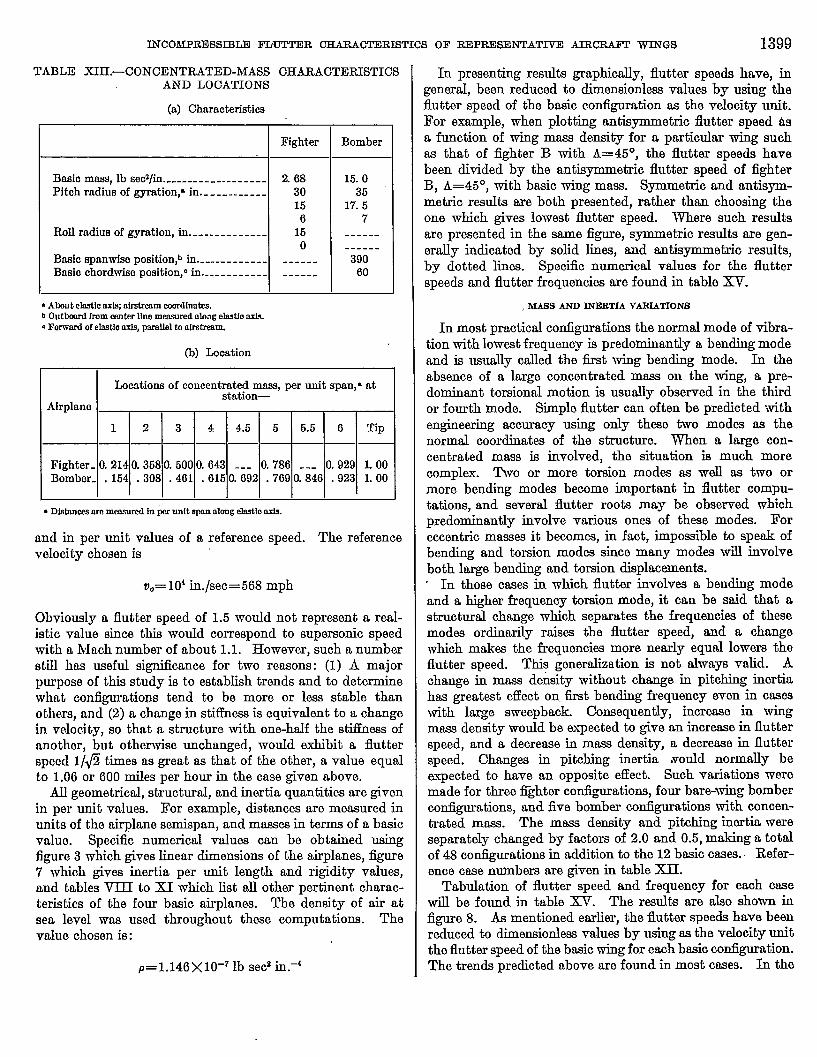
Concentmted masses on fighter wings usually consist offuel tanks, bombs, or similar stores. It is impossible, there-fore, to select a single value for mass and inertia which canbe regarded as typical. For certain positions many valuesfor mass and inertia were chosen, although in most of thecases studied the number of values was restricted by thetime available for computations. For reference purposes,the basic mass for fighter planes was arbitrarily chosen tobe one-quarter of the mam of the entire wing (half of the masaof one side), the pitching radius of gyration was set equal to30 inches, and the roll radius of gyration was aasumed to be16 inches or less. Specific data for the two iighters are listedin trtbloXIII.
Concentrated masses for bomber airplanes are usually en;gine nacelles, with a mass which can be predicted within afactor of 2. Nevertheless,“it is of some interest to study theeffect of various mass values in these cases also. Basic massvalue for both bombers was assumed to be 15 pounds-secondssquared per inch, which corresponds to a weight of nearly(3,000pounds. Pitching radius of gyr@ion was assumed tobe 36 inches. Basic mass position was assumed to be at the0.4&span position and 60 inches in front of the elastic axis.These data are also tabulated in table XIII.
The concentrated-mass characteristics varied in this studyare:
(1) Mass(2) Pitching inertia about center of mass(3) Spanwise location(4) Chordwise location(5) Pitching flexibfity
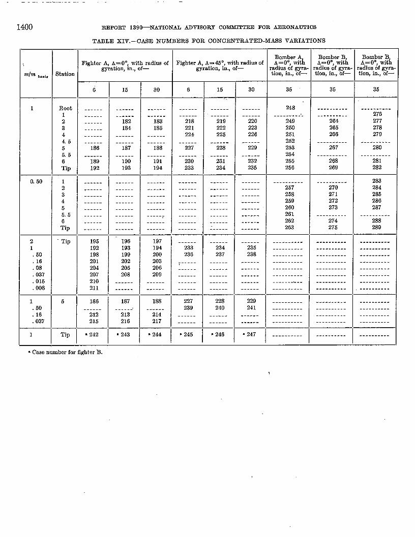
The assignment of case numbers is more difiicult for thisphase of the study. Although speciiic spanwise positionswere chosen, it was not possible to choose chordwise positionsbeforehand. The chordwise positions were chosen as thedata were obtained. In some cases more than 20 positionswere used for a given spanwise location. Consequently, onecase number was assigned to all chordtise variations at ngiven spamvise location. A summary of all variations withthe corresponding case numbers is given in table XIV.
Pitching flexibility of the concentrated mass was variedin six cases involving both bombem. In all cases, the chord--wiselocation of the center of mass wwabasic (table XIII).In three caaes the maw was in basic spantie position and
TABLEXI’.-CHARACTERISTICS OFBASICBOMBERB
(a) Physicalcharaoteriatk.
Swmpbackangle,A, d~---------------------------- 30SemisPan of wing,~ 1, ti----------------------------- 845cell size for tlnite-clMerencestructure, A~, in----------- 130Root chord,b b,, h---------------------------------- 170Tip chord, b b= ti----------------------------------- 70Taper mtio---------------------_------------;----- 2.43Wing elactic axia, percent chord ---------------------- 40Wing center of ream, percent chor&------------_----- 40Total wing mass external of fuselage mr lb sec$/in----- 48.7Fuselage mass, mj, lb m&fi -------------------------- 120Fuselage radi~ of gyration, pitclqe in------------------ 240Fuselage radiuc of gyration, ro~ in------------------- 50Fuselage canter of mrm9 aft of elactic ati, in----------- 150Tail center of pressure aft of elastic axis, in------------- 700Tail area, sh in------------------------------------- 20,000Air density, p, lb w&/ti.4---------------------------- 1.146 X 10⁻⁷
(b) Inertia and stiffn~ values lumped for finite diikencc structure
r’ 13tition------------------ 1 2 3 4 56
Per unit spana--__------ O.1540.308 0.461 0.6150.769 0.923Half ohord,b b, in-------- 77.3 69.6 61.9 64.2 46.5 38.8Lumped maw, E, lb
se&/in.-------------- 6.28 5.23 4.26 3.35 2.7 2.47Lumped pitch inertia--- 3, 9403,0802,2001,560 910 390
UOIO~(d~jEI)------ 7.12 18.8 31.0 64.9 91.6 141.0 ----dlOIOf (dy/(3J_)------- 6.31 15.5 22, 6 42.2 77.8 110.0 60
* Mmmrai rdcngekuth ads.bMewred peqmndIdar todasHcY@soAbmt Ck@O arkds-valnm archunpcdbtween lnassstatlom.
in three oasea the mass was at the tip. Case numbers aregiven in table XIV.
TRENDSIN FLUTTERCHARACTERISTICS
REFERENCEQUANTITIESANDGRAPHICALPRBENTATION
Results of the study of trends in flutter characteristicswhich are listed in table XV are given in miles per hour
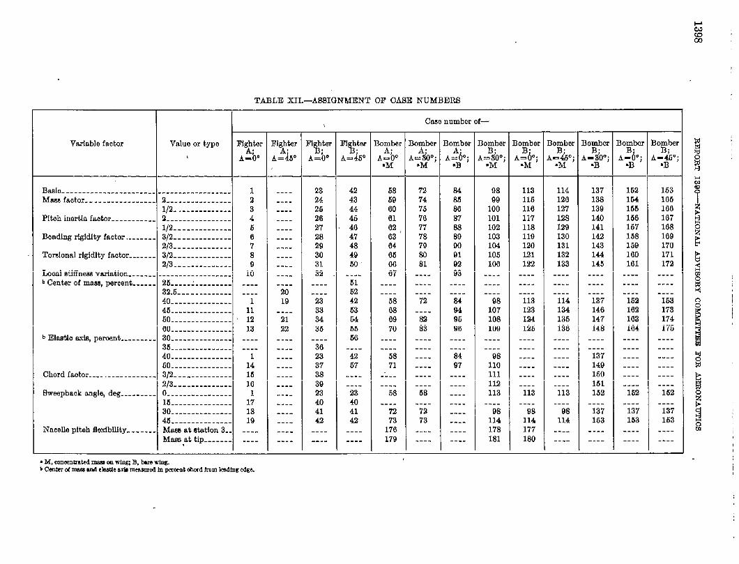
TABLE XIL-A2131GNMENT On (MSE NUMBERS
Clam nnmbm of—,
Vwlable factor Valuo or type l“ig~ter Fl&er Fit-w F1 htw h~twr Iqber Bofber Bo~ber Bo~ber Bo~ber Bor&r Bo&ber Bor#mr.%. $150 ~ ~ ~ ~ ~ ~ ~ ~ ~
A-h” A=&” A,=MW A=#O; A # ; A=ti”; A~&i A.=&; A_3iT; A_ljO; A_~O;
*M .M .M -B -B ~B
Boo----------------------- ------------------ 1 ---- 2s 42 68 72 84 98 113 114 137 162 163
Mufaotir--.-------------- 2---------------- 2 ---- 24 43 59 74 68 99 115 120 138 164 106
1/2- . . . . . . . . . . . . . 3 ---- 26 44 00 75 80 100 110 127 139 155 100
P1tah inertia faetOr-.---.--.-- 2---------------- 4 ---- 20 46 01 70 37 101 117 12.s 140 156 107
l/2-------------- 6 ---- 27 40 02, 77 38 102 118 129 141 167
Bonding rfgidlty faotm .----.-- 3~-------------- 0 . . . . 28
103
47 03 78 89 103 119 130 142 158 109
2/3-------------- 7 ---- 29 46 04 79 WI lc4 MU 131 143 159 170
Tm-donal rlgidlty factor ------- 3/2-------------- 8 ---- 30 49 05 24 91 105 lm 132 144 100 171
2p-------------- 9 ---- 31 Ml 00 81 92 Iw 122 133 145 101 172
I.aml tinwa varlntiOn------ -----------------. 10 ---- 32 ---- 07 ---- 98 ---- ---- ---- ---- ---- ----
b Cent-w of mud, percent -.-... 25.--.--.--.--.-- ---- ---- ---- 51 ---- ---- ---- ---- ---- ---- ---- ---- ----
32,6------------- ---- 20 ---- 52 ---- ---- ---- ---- ---- ---- ---- ---- ----
40--------------- 1 19 28 42 .58 72 84 98 113 114 137 162 163
46--------------- 11 ---- 33 53 0s ---- 94 107 128 134 146 102 179
50--------------- 3 12 21 34 64 69 m 96 108 124 135 147 103 174
oo--------------- 13 22 35 55 70 83 90 109 126 136 148 104 175
b Eltio &-i@ pemwnt--------- 30--------------- ---- ---- ---- E-2
35-----.---.----- ---- ---- 30 ---- :::: :::: :::: :::: :::: :::: ---- :::: ::::
----
40--------------- 1 ---- 23 42 68 ---- 84 98 ---- ---- 137 ---- ----
60--------------- 14 ---- 87 67 71 ---- 97 110 ---- ---- 149 ---- ----
Ohord fe.ator---- .------------ 3/f2-------------- 15 ---- 38 ---- -:-- ---- ---- 111 ---- ---- 160 ---- ----
213-------------- 16 ---- 39 ---- ---- ---- ---- 112 ---- ---- 151 ---- ----
Bwmpbaok anglq deg--------- o---------------- 1 ---- 23 23 6s 68 ---- 113 113 113 162 162 152
15--------------- 17 ---- 40 40
30--------------- 18 ---- 41
---- ---- ---- ----
41 --k -;i- :::: --ii --ii 98 137 137 137
45--------------- 19 ---- 42 42 73 73 ---- 114 114 114 lba 153
Nacelle plteh flexibility ------- Mem at station 3. . ---- ---- ---- ----
163
170 ---- ---- 178 177 ---- ---- ---- ----
Mare at tip-_----- ---- ---- ---- ---- 179 ---- ---- 181 160 ---- ---- ---- ----
INCOMPRDSSI13LDl?LWIWDR CHARAfXERISTICS OF REPRESENTATIVE AIRCRAJ?T WINGS 1399
TABLE XIH.-CONCENTRATED-MASS CHARA~EFUSTICSAND LOCATIONS
(a) Characteristka
Fighter
Basio mass, lb w2/b..---------.-----.- 268Pitoh radius of gyration,’ in------------ 30
156
Roll radius of gyration, in-------------- 150
Basio spanwise position,b in.----.------- ------Brmio ohordwiso position,” in------------ ------
* Abut C~O nXJWnll%trmmmOrdinOtES.b Outb.mrdfmm mnttr Hnemeasurd aleag elestfe&. For!vord of elostlo~ pnmllel to afm~m.
(b) Location
Bomber
15.035
17. s7
------------390
60
ILocations of ccncentrd$onw per unit span,* at
Afrplano
1 2 3 4 4.5 6 5.5 6 Tip
Fighter- O.214 0.368 0.500 0.643 --- 0.786 --- 0.929 1.00Bomber- . 154 .308 .461 .615 0.692 .769 a846 -923 1.00
. DfEtieeserommmmxfin pwdt ~ alengelmtbark.
ttnd in per unit valuea of a reference speed. The referencevelocity chosen is
vO=l(Y in./aec=668 mph
Obviously n flutter speed of 1.5 wouId not represent a retd-istic value since this would correspond to supersonic speedwith a hlach number of about 1.1. However, such a numberstill has useful signiikance for two reasons: (1) A majorpurpose of this study is to establish trends and to determinewhat configumtiom tend to be more or less stable thanothers, and (2) a change in stiilness is equivalent to a changein velocity, so that a structure with one-half the stitlness ofanother, but otherwise unchanged, would exhibit a flutterspeed I/@ times w great as that of the other, a value equalto 1.06 or 600 miles per hour in the case given above.
All geometrical, structural, and inertia quantities are givenin per unit values. For example, distances are measured inunits of the airplane semispan, and masses in terms of a basicvalue. Specific numerical values can be obtained usingfigure 3 which gives linear dimensions of the airplanes, figure7 which gives inertia per unit length and rigidi@ values,and tables VIII to XI which list all other pertinent charac-teristic of the four basic airplanes. The density of air atsea level was used throughout these computations. Thevalue chosen is: \
P=1.146X10⁻⁷ lb sed in.+
In presenting reauhk graphically, flutter speeds have, ingeneral, been reduced to dimensionless values by using theflutter speed of the bwic configuration as the veloci~ unit.For example, when plotting antisymmetric flutter speed &a function of wing mass density for a particular wing suchas that of fighter B with A=45°, the flutter speeds havebeen divided by the antisymmetric flutter speed of fighterB, A=45”, with basic wing mass. Symmetric and antisyn-metric results are both presented, rather than choosing theone which gives lowest flutter speed. Where such resultsare presented in the same figure, symmetric results are gen-erally indicated by solid lines, and antisymmetric results,by dotted lines. Specific numerical values for the flutterspeeds and flutter frequencies are found in table XV.
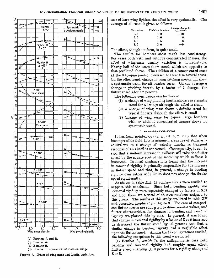
, MASSANDlNEllTIAVARIATIONS
In most practical configurations the normal mode of vibra-tion with lowest frequency is predominantly a bending modeand is usually called the first wing bending mode. In theabsence of a large concentrated mass on the wing, a pre-dominant torsional motion is usually observed in the thirdor fourth mode. Siple flutter can often be predicted withengineering accuracy using only these two modes as thenormal coordinates of the structure. When a large con-centrated mass is involved, the situation is much morecomplex. Two or more torsion modes as well as two ormore bending modes beccme important in flutter compu-tations, and several flutter roots may be observed whichpredominantly involve various ones of these modes. Foreccentric massea it becomes, in fact, impossible to speak ofbending and torsion modes since many modes will involveboth large bending and torsion displacements.- In those cases in which fluttsr involves a bending modeand a higher frequency torsion mode, it can be said that astructural change which separates the frequencies of thesemodes ordinarily raises the flutter speed, and a changewhich makes the frequencies more nearly equal lowers theflutter speed. This generalization is not always valid. Achange in mass de~lty without change in pitching inertiahas gnmtest effect on. first bending frequency even in caseswith large sweepback. Consequently, increase in wingmass density would be expeoted to give an increase in flutterspeed, and a decrease in mass densiw, a decrme ~ flutterspeed. Changes in pitching inertia xould normally beexpected to have an opposite effect. Such variations weremade for three Kghter configurations, four bare-wing bomberconfigurations, and five bomber configurations with concen-trated mass. The mass density and pitching inertia wereseparately changed by factors of 2.0 and 0.5, making a totalof 48 configurations in addition to the 12 basic cases.. Refer-ence case numbers are given in table XII.
Tabulation of flutter speed and frequency for each casewill be found in table XV. The results are also shown in&ore 8. & mentioned earlier, the flutter speeds have beenreduced to dimensionlessvalues by using as the velocity unitthe flutter speed of the basic wing for each basic configuration.The trends predicted above are found in most cas~. In the
_.——... ——- .—--- —.- .— .-—. —.
1400 R33POET 139&NATIONAL ADVISORY COMMITTEE FOR AERONAUTICS
TABLE XIV. -CASE NUMBERS FOR CONCENTRATED-MASS VARIATIONS
Bomber BFightex ~ A= O”{with radius of Fighter A, A=4S~, with radius of ::%,ek% :%?%% A= 0°, wit~
~tion, m., of— gyration, m., of— radius of gyra- radius of gyra- radius of gyra-‘lln bada Station tion, in., of— tion, in., of— tion, in., of—
6 15 30 6 15 30 35 35 36
1 Root ------ ------ ------ ------ ------ ------ 248 ---------- ----------1 ------ ------ ------ ------ ------ ------ -------- --- ---------- 2762 ------ 182 183 218 219 220 249 264 2773 ------ 184 185 221 222 223 250 265 2784 ------ ------ ------ 224 225 226 261 266 2794.5 ------ ------ ------ ------ ------ ------ 252 ------.---- ----------5 186 187 188 227 22a 229 253 267 2805.5 ------ ------ ------ ------ ------ ------ 2s4 ---------- ----------6 189 190 191 230 231 2-32 255 268 281Tip 192 193 194 233 234 235 256 269 282
0.50 1 ------ ------ ------ ------ ------ ------ ---------- ---------- 2832 ~----- ------ ------ ------ ------ ------ 267 270 2843 ------ ------ ------ ------ ------ ------ 258 271 2864 ------ ------ ------ ------ ------ ------ 259 272 2865 ------ ------ ------ ------ ------ ------ ‘ 260 273 2875.5 ------ ------ -----: ------ ------ ------ 261 -------_-- ----------6 ------ ------ ------ ------ ------ ------ 262 274 288Tip ------ ------ ------ ------ ------ ------ 263 275 280
2 . Tip 195 - 196 197 ------ ------ ------ ---------- ---------- ----------1 192 193 194 233 234 235 ---------- ---------- ----------.60 198 199 200 236 237 238 ---------- ---------- ----------.16 201 202 203 i----- ------ ------ ---------- ----------.08
----------204 205 206 ------ ------ ------ ---------- ---------- ----------
.037 207 208 209 ------ ------ ------ ---------- ---------- ----------
.015 210 ------ ------ ------ ------ ------
.008-------&-- ---------- ----------
211 ------ ------ ------ ------ ------ ---------- ---------- - ----------
1 5 186 187 188
1“
227 22% 229 ---------- ------.--- ----------.50 ------ ------- ------ 239 241 ---------- ---------- ----------.16 212 213 214 ------ ------ ------ ---------- ---------- ----------.037 215 216 217 ------ ------ ------ ---------- ---------- ----------
1 Tip * 242 * 243 a 244 ● 245 ● 246 ~ 247 ---------- ---------- ----------
* Case number for fighter B.
\
INCOhlPRESSD3LE FLUTTER CHARACTERISTICSOF REPRESENTATlT13AIRCILKFTWINGS 1401
1,1
Lo
.9
.s
1.1
1.0
.9
,8
1.1
1.0
,9
,8
1,1
1.0
,9
I.2
1.1
1.0
.9
1.2
1.1
1,0Vf
.9
.8
.71,1
I.0
.9
1.2
1.1
1,0
,9
1,2
1.1
1.0
.9
1.1
1.0
.9
1.2
1.1
1.0
.91.2
1.1
1.0
‘9 .5 1.0 1.5 2.0 .5 1.0 1.5 20Wing moss density Wing pitching inertia
(a) Fighters A and B.(b) Bomber A.(o) Bomber B.(d) Bomber B; concentrated mws on wing.
FXWBE 8.—Effeot of wing mass and inertia variatio=
case of bare-wing fighters the effect is very systematic. Theaverage of ill casea is given as follows:
Messtie Pm lnErt18value “’8%%%’0.5 LO –1220 L o 6LO 5 8L o 2:0 –9
The effect, though uniform, is quite small.
The results for bombers show mwh less consistency.
For cases both with and without concentrated masses, theeflect of wing-maw densi@, vtiation is unpredictable.
Nearly half of the cases show trends which are opposite tothat predicted above. The addition of a eoncentmted mass
at the 0.46-span position reversed the trend in several cases.
On the other hand, change in wing pitching inertia did showa systematic trend for all bomber cams. On the aver~~e achange in pitching inertia by a factor of 2 changed theflutter speed about 7 percent.
The following conclusions can be drawn:(1) A change of wing pitching inertia shows a systematic
trend for all wings although ~he effect is small.(2) A change of wing mass shows a deiinite trend for
typical fighters although the effect is small.(3) Change of wing mw.s for typical large bombers
with or without concentrated mww shows nosystematic trend.
~= VARIATIONS
It has been pointed out (e. g., ref. 1, p. 783) that wheniiicompressible fluid flow is assumed, a change of sti.fhwssisequivalent to a change of veloci~ insofar as transientresponse of an airfoil is concerned. Censequentiy, it can besaid that a uniform iucrtwe in stiffness will raise the flutterspeed by the square root of the factor by which stfiess isincreased. In most airplanes it is found that the increasein torsional rigidity is primarily responsible for the increasein flutter speed and that, in general, a change in bendingrigidity over rather wide limits does not change the flutterspeed significantly.
As shown in table XII, 12 contlgurations were studied tosupport this conclusion. Site both bending rigidity andtorsional rigidity were separately changed by factors of 0.67and 1.50, there are a total of 48 case numbers assighed tothis group. The results of this study are listed in table XVand presented graphically in figure 9. For ease of compari-son flutter speeds are conv~ted to dimensionlessvalues, andflutter characteristics for changes in bending and torsionalrigidity are plotted side by side. In general, it was foundthat change in torsionalrigidity by a factor of %or %increasedor decreased the flutter speed by 20 percent and that asimilar change in bending rigidi~ had a negligible effectupon the flutter speed. Among the 12 configurations studied,the following exceptions to this trend were noted:
(1) Bomber A, A= O”: In the antisymmetric case bothbending and torsional riggdi@ had roughly equal effect,flutter speed changing +10 percent for a rigidity change of%or %.
.—
1402 REPORT 139tiNATIONAL ADVISORY COMMITTEE FOR AERONAUTICS
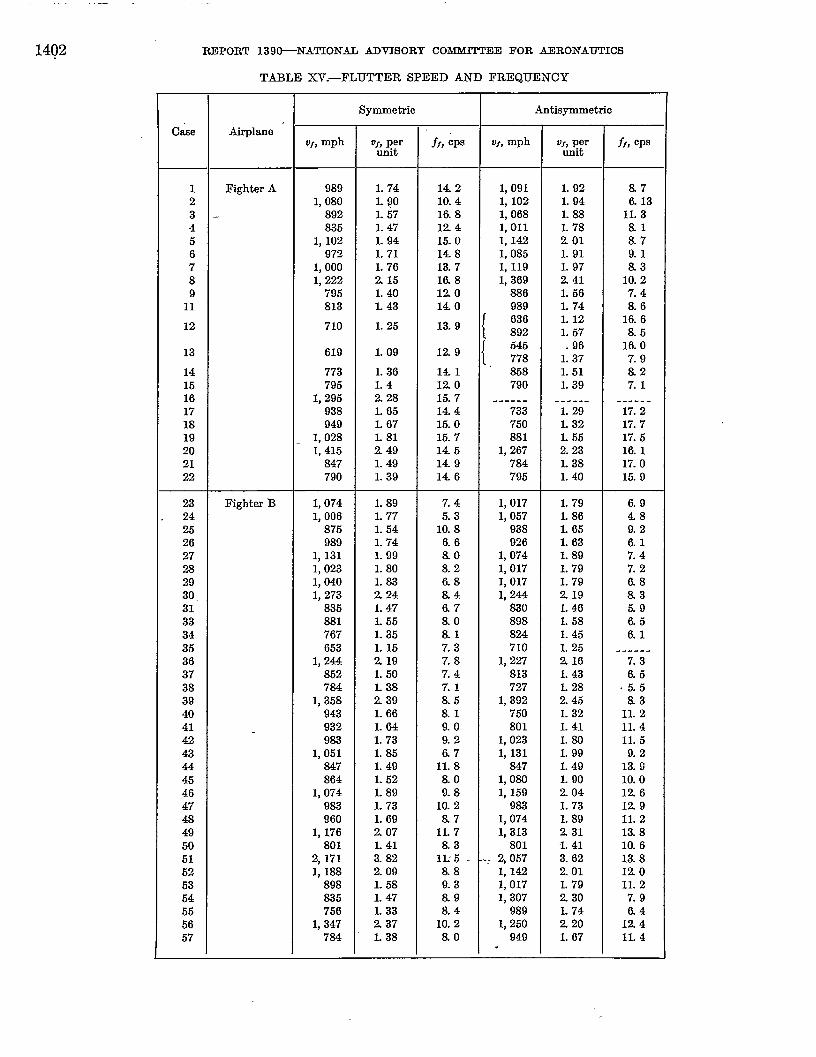
TABLE XV.-FLUTTER SPEED AP7D FREQUENCY
Symmetric Antisymmetrio
CA Airplane ‘VI,mph OJ,per ff, CP Vr,mph VJ,per ff, CPS
Unit unit
1 Fighter A 989 1.74 14.2 1, 091 L 92 &72 1, 080 L QO 10.4 1, 102 1.94 6.133 - 892 L 57 lfl 8 1, 068 L88 11.34 835 1.47 124 1,011 1.78 &l5 1, 102 L 94 15.0 1, 142 201 8.76 972 L 71 148 1,085 L 91 9.17 1,000 1.76 13.7 1, 119 1.97 8.38 1, 222 215 l& 8 1, 369 241 10.29 795 1.40 120 886 1.66 7.4
11 813 L 43 140 989 L 74 8.6
12 710 1.25 13.9{
636 L 12 16.6892 1.57 &b
13 619 L 09 129{
646 .96 16.0778 1.37 7.9
14 773 L 36 141 . 868 L 51 8.215 796 1.4 120 790 1.39 7.116 1,295 228 15.7 .----- --.--- ------17 938 L 65 14.4 733 1.29 17.218 949 L 67 15.0 750 L 32 17.719 1,028 L 81 15.7 881 L 55 17.520 1,415 _ 249 14.5 1, 267 223 16121 847 L 49 149 784 L 38 17.022 790 1.39 146 796 1.40 15. f)
23 Fighter B 1,074 1.89 7.4 1,017 1.79 6.924 1,006 L 77 5.3 1,057 1.86 4.826 875 1.54 10.8 938 1.65 9.226 989 1.74 6.6 926 1.63 6.127 1, 131 1.99 &o 1, 074 1.89 7.428 1,023 L 80 8.2 1,017 L 79 7.229 1,040 L83 &8 I, 017 1.79 6.830. 1,273 224 &4 1, 244 219 &331 835 1.47 6.7 830 1.46 6.933 881 L 55 8.0 898 1.68 &634 767 L 35 &l 824 1.45 6.136 653 L 16 7.3 710 L 26 ------36 1, 244 219 7.8 1, 227 216 7.337 862 1.50 7.4 813 1.43 t1638 784 L38 7.1 727 L28 .5539 1,358 239 &6 1,392 246 &340 943 1.66 al 760 1.32 11.241 932 L64 9.0 801 1.41 11.442 983 L 73 9.2 1,023 1.80 11.643 1,051 1.85 6.7 1, 131 L 99 9.244 847 1.49 11.8 847 1.49 13.945 864 1.62 8.0 1,080 1.90 10.046 1,074 L 89 9.8 1, 159 204 12647 983 L 73 10.2 983 L 73 12948 960 L 69 8.7 1, 074 1.89 11.249 1, 176 207 lL 7 1,313 231 13.850 801 L 41 8.3 801 1.41 10.661 2, 171 3, 82 1E6 - - -, .2,057 3.62 13.862 1, 188 209 8.8 1, 142 201 12063 898 L 58 9.3 1,017 L 79 11.264 835 L 47 8.9 1,307 230 7.965 766 L33 8.4 989 L 74 (?%456 1,347 237 10.2 1,250 220 12457 784 L38 %0 949 1.67 lL 4
.
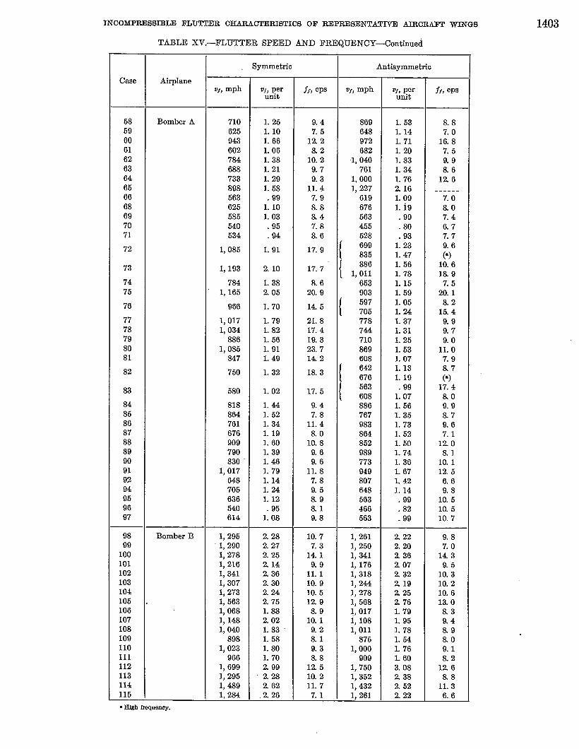
INCOMPRESSIBLE FLU’J?J?DRCHARA~RISTICS OF REPR13SENTNITVD ADWRAKI! WINGS 1403
Case
58596061626364656668697071
72
73
7475
76
7778798081
82
83
84858687888990919294959697
9899
10010110210310410510610710s109110111112113114115
TABLE XV.—FLUTTER SPEED AND FREQUENCY-Contiiued
Airplane
Bomber A
Bomber B
symmetric
710625943602784688733898563625685540534
1,085
1, 193
7841, 165
966
1,0171,034
8861,086
847
750
580
818864761676909790830-
1,017648705636540614
1,2961,2901,2781,2161, 3411, 3071,2731, 5631,0681, 14s1,040
8981,023
9661, 6991,2951, 4891,284
UJ,perunit
1.261.101.661.061.381.211.291. 6S.99
1.101.03.96.64
1.91
210
1.382+05
1.70
1.791.821.661.911.49
1.32
L 02
1.441.521.341.191.601.391.461.791.141.241.12
951:08
2.282.272.252142362.302.242.761.882.021.831.581. so1.70299
“228262
.226
fr, CPS
9.47.5
122&2
10.29.79.3
11.47.98.88.47.88.6
17.9
17.7
&620.9
145
21.817.419.323.7142
18, 3
17.6
9.47.8
11.4&o
10.89.69.6
11.87.89.58.98.19.8
10.77.3
14.19.9
11.110.910.51298.9
10.19.2al9.3&8
12510.211.77.1
Adisymmetio
VI, mph
869648972682
1, 040761
1,0001,227
619676663455628699835886
1,01166390369770577s744710869608642676563608886767983864852989773949807648563466663
1, 2611,2501, 3411, 1761, 3181, 2441,2781, 5681,0171, 1081,011
8761,000
9091,7501,3521,4321,261
of, perunit
1.631.141.711.20-1.831.341.762161.09L 19.99.80
931:231.471.561.781.151.591.051.241.37L 31L 251.531.071.131.19
99i 071.661.361.731.621.501.741.36L 671.421.14.99.82.99
2222.202362072322192,252761.791.951.781.54L 76L 603.08238252222
ff, OPS
8.87.0
16.87.59.9&6
126------
7.08.07.46.77.79.6P)
10.618.97.5
20.1&2
1549.99.79.0
11.07.98.7(~)
17.4&o9.98.79.67.1
1208.1
10.112.66.69.8
10.510.510.7
9.87.0
1439.6
10.310.210.613.0&39.48.9&o9.1&2
126&8
11.36.6

1404 REPORT 139 bNATIONAIJ ADVISORY COMMITTEE FOR AERONAUTICS
TABLE XV.—FLU’M’ER SPEED AND FREQUENCY-Concluded
Symmetric Antieyrnmetrh
case AirplaneVI,mph VJJper ff? CPS w) mph vf, per ff, CPS
unit unit
116 Bomber B 1, 284 226 13.7 1, 347 237 15.3117 1,227 2.16 9.4 1,239 218 8.4
118 1,341 2+36 10.8 1,477 260{
9.611.4
119 1,284 226 10.2 1,284 2.26 9.3120 ‘ 1,250 220 10.6 1,347 237 11.3121 1, 534 270 13.0 1, 653 291 13.8122 1,051 L 85 &3 1,051 1.85 7.6123 1, 108 1.95 9.2 1,074 1.89 8.3124 . 983 1.73 86 955 1.68 7.812s 813 1.43 7.4 773 1.36 7.0126 1, 523 268 8.8 1,477 260 7.8127 1,472 259 155 1,409 248 14.8128 1, 392 245 10.4 1,335 235- 10.5129 ; 1, 557 274 122 1, 500 2,64 120130 1, 528 269 11.5 1,477 260 11.0131 1,420 250 11.3 1, 386 2.44 10.7132 1, 738 3.06 126 1, 699 299 13.1133 1, 250 220 9.4 1,205 212 9.0134 1, 364 240 11.0 1,284 226 11.0135 1, 261 222 10.2 1, 188 209 10.6136 1, 119 1.97 -8.7 1,080 1.90 10.2137 1, 165 205 7.1 ‘ 1,244 219 10.3138 1,023 1.80 4.5 1,239 2.18 7.0139 1,261 222 13.7 1, 205 212 14.2140 1,108 1.95 7.0 1, 170 2.06 9.8141 1, 182 208 7.3 1,284 226 10.4142 1,205 212 8.1 1,267 223 10.7143 1, 108 1.95 6.1 1,239 218 9.6144 1,358 239 7.5 1, 517 267 11.8146 9X3 1.73 &6 1,034 L 82 &7146 1,074 1.89 7.3 1, 131 1.99 10.2147 1,023 1.80 7.7 1,034 1.82 9.6.148 898 1.58- &3 898 1.58 8.6149 972 1.71 6.7 1,023 1.80 9.7160 881 1.55 7.2 909 1.60 8.5151 1,483 261 7.3 1,665 293 10.8152 1,216 214 10.1 1,216 214 10.4153 1, 114 1.96 6.6 1,421 250 10.4154 1,193 210 6.5 1,216 214 6.7155 1,159 204 13.8 1, 170 206 13.9156 1,136 200 9.4 1, 142 201 9.2157 1,261 222 10.5 1,261 222 10.4158 1, 199 211 10.0 1,193 210 9.9159 1, 199 211 9.9 1, 182 208 10.1160 1,466 2’58 121 1,449 255 124161 977 L 72 al 977 1.72 8.1162 1,057 1.86 9.9 1,057 L 86 9.8163 949 1.67 9.4 960 1.69 9.6164 818 1.44 8.7 818 1.44 86165 1,040 L 83 43 1,438 253 7.16166 1,2-44 219 10.2 1, 375 242 14.0167 1,080 1.90 6.4 1, 347 2.37 10.0168 1, 125 1.98 6.6 1, 460 257 10.5169 1,205 212 7.4 1,455 256 11.2170 1,000 1.76 5.5 1,386 244 9.7171 1, 227 216 6.7 1,699 299 11.9172 983 1.73 6.0 1, 188 209 9.1173 1, 040 1.83 6.5 1,313 231 10.9174 1,000 L 76 6..5 1,216 214 11.0175 920 1.62 6.5 1,085 1.91 10.5

~COMPRESSIBLE FLU’IT’31R CHARACTERISTICS OF RI!lPREISENTATIVE AlRCR41Y1’ WINGS
-1.3-Fighter A o Symmetr[c
,2 A=O” o Antisymmetric
1.1
I .0
.9
r / ‘
1.1y T
R hte: B~:: l!O
— ~
9\
, ,/, P
/.B
f/
/1.1
u
Lo ~ --.,
- ❑ —
9Fighter B
.8A=45°
,~
~ (o) 1I I
L3
1.2 .
A=O”1.1 /
/ -a- // “
Lo /9 ~’
I/
~
9 , / I-
/Y
87
1.2- //
-0.
1.1/. /
v A=&Cone.moss
Lo% <
—-o
.9 /J\.
/ d’.8
7//
/1.1 /
/ d
1.0 k - ~\/
9 /s“ A=30°
.BCarw. rmss
(b) f7 I I
.5 LoI
M .5 LO 15
(n)(b)
W witkmimol rigidity Per tit betii rigidty ““-
Fighters A and B.Bomber A; bare wing and concentrated mase on wing.
1405
tI.3 0Symmetric
1.2OAnti symmetric
A=OO1.1
Lo
.9
8d
/
1.1
VfLO & ~ =
A=30°.9
.8/
1.1 /
A= 45°-
Lo+
-cl-
.9 / 7/ ~
.8 I 1
I .3 I
I I I I {[.2 P’,. -,
I. I 1.// I I
. Lo
.9 J
.8Vf P
1.1
A= 30°1.0
.9
8 /
1.1
Is) A I
I II
A=45”H ‘—
.9(d)
ILo 15
.81 + 1’ I I I I I I y1.0 1.5
Per witta-shml rigidity ‘- Per wit Iwxiing rigidity
(o) Bomber B; bare wing.(d) Bomber B; concentrated maas on wing.
FIGURE 9.—Flutter speed as a funotion of wing rigidity. .
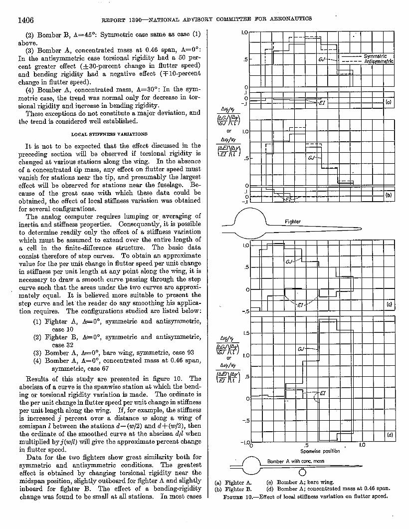
1406
(2) Bomber B, A=45”:above.
REPORT 139bNATIONAIJ ADVISORY CO~ FOR AERONAU’IWS
Symmetric case same as cfse (1)
(3) Bomber A, concentrated mass at 0.46 span, A=OO:In the nntisymmetric case tomional rigidity had a 50 per-cent greater effect (+30-percent change in flutter speed)and bending rigklity had a negative effect (+10-percentchange in flutter speed).
(4) Bomber A, concentrated mass, A=30°: In the sym-metric case, the trend was normal only for decrease in tor-sional rigidity and increase in bending rigidity.
These exceptions do not constitute a major deviation, andthe trend is considered well established.
LOCALSTIFFNE9SVARIA’I’1ONS
It is not to be expected that the effect discussed in theprecading section will be observed if torsional rigidity ischanged at various stations along the wing. In the absenceof a concentrated tip mas, any effect on flutter speed mustvanish for stations near the tip, and presumably the largesteffect will be observed for stations near the fuselage. Be-cause of the great ease with which these data could beobtained, the effect of local stiffness variation was obtainedfor several configurations.
The analog computer requires lumping or averaging ofinertia rmd stifhmss properties. Consequently, it is possibleto determine readily only the effect of a stifl%ess variationwhich must be assumed to extend over the entire length ofa cell in the finite-difference structure. The basic dataconsist therefore of step curv-. TO obtti an approximatevalue for the per unit change in flutter speed per unit changein stiffness per unit length at any point along the wing, it isnecessary to dram a smooth curve passing through the stepcurve such that the areas under the two curves are approxi-mately equal. It is believed more suitable to present thestep curve and let “the reader do any smoothing his applica-tion requires. The configurations studied are listed below:
(1) I?ighter A, A= O”, symmetric and antisymmefiric,case 10
(2) Fighter B, A* O”, symmetric and antispnmetz-ic,case 32
(3) Bomber A, kOO, bare wing, symmetric, case 93(4) Bomber A, A=OO, concentrated mass at 0.46 span,
symmetric, case 67
Results of this study are presented in iignre 10. Theabscissa of a curve is the spanwise station at which the bend-ing or torsional rigidity variation is made. The ordinate isthe per unit change in flutter speed per unit change in stiessper unit length along the wing. If, for example, the stiflhessis increased j percent over a distance w along a wing ofsemispan t between the stations d— (w/2) and d+ (w/2), thenthe ordinate of the smoothed curve at the abscissa dp?whenmultiplied by j(w/Z) will give the approximate percent changein flutter speed.
Data for the two fighters show- great similarity both forsymmetric and antis~etric conditions. The greatesteffect is obtained by changing torsional rigidity near themidspan position, slightly outboard for fighter A and slightlyinboard for fighter B. The effect of a bending-rigiditychange was found to be small at all stations. In most cases
-3&(%-9(%
or
tif/vf
(%%---
LoI- —-- -= --
Ir- -. L_ --
.5 - ,— syrnrnetfic
! GJ- --+ _____ ~. Symnletrk
--
0.10 _ J ,
-J ‘-” -EI (a)
1.0 r ‘--
:- ‘ -1
.5 - GJ- -
1
0 =1
.1 -1. 1.- (b)
-?
Lo r 1
-1I
GJ---~— 1
.5
0 1J I
I \ .
‘%‘EI- ““’ (c)-.5 1
I
[.5f%f/?
(%%4 ,0GJ -—
ar
Avf/vf
(3(?) 5 ‘I
t y..
“-1 a0
-.5 .
I (d)-1.OO .5 1.0
Spmwise positibn
(a) Fighter L (o) Bombr A; bare wing.(b) Fighter B. (d) Bomber A; concentrated mass at 0.46 span,
FIGURB 10.—Effeot of local stiffness variation on flutter speed.

INCOMPRESSIBLE FLUTTER CHARACTERISTICS OF REPRESENTATIVE AIRCIMF’T WINGS 1407
a smrdlnegative effect was observed, the flutter speed drop-ping slightly M the bending rigidity was increased.
Bomber A without concentrated mass showed a similartrend with the following exceptions:
(1) Maximum improvement was obtained by changingtorsional rigidity near the root of the wing (0.25*panposition).
(2) Increase in bending rigidity was observed to decreasethe flutter speed by an amount which was 5 to 10 timesgreater than that for fighter A.
Addition of a concentrated mass at spanwise station 0.46has a great effect on this characteristic. The mass chosen istypical for an airplane engine and is sufficiently large so thatthe wing is, to a certain extent, pinned at this”point for theparticular flutter root involved. Consequently, stiifncsschanges inboard of the engine have a negligible effect, andchanges outboard have an effect very similar to that observedfor a bare wing of reduced length.
It shouId be remarked at this point that the result dis-cussed above is not to be regarded as a trend for all con-figurations. When the flutter is primarily an outer-wingbending-torsion flutter, this result is to be expected. Ex-perience has shown, however, that occasionally an inner-panel torsion mode is involved in flutter, and change intorsional rigidity outboard of the nacelle has no significanteffect. It is unfortunate that such a configuration was notinvestigated for this report.
CENTEE-OF-MASSLOCATION
The location of the wing center of mass has a great effectupon flutter speed of an airplane wing. The general trendis that flutter speed increases as the center of mass movesforward. It is not generally true that it is at a constantchord lomtion at all spanwise stations. Howevar, for pur-poses of studying the tiends, it is necessary to asaume somebasic position for the center of mass. Past experience hasshown that a center~f-mass location near the elastic axis(usually slighdy aft) is both realistic and typical. For thisreason the basic position of the center of mass was assumedto be the elastic axis or 40 percent chord. Variation incenter-of-mass location was between the 25- and 60-percent-chord points. Thirteen contlgurations were studied, thevarious center-of-mass locations comprising 53 casea listedin table XII.
The results a~e listed in table XV and are shown graphi-cally in dimensionless form in figure 11. The general trendis thut the flutter speed increases as the center of mass movesforward and decreasea as the center of mass moves aft,except for center-of-mass locations far behind the @&icaxis. For positions near the elastic axis the flutter speedchanges about 3 percent for a shift in center of mass equalto 1 percent of the chord. For the extreme aft positions(60 percent chord) most of the curves become quite flat,and in about four cases the flutter speed has started to riseslightly as the center of mass is moved farther aft. On theother hand, the curves become very steep for centermf-masslocations forward of the elastic axis. In most cases theincrease in flutter speed was so great that data could notbe obtained for the 25- and 32.5-percent-chord locationsbecause the flutter speed greatly exceeded the divergence
17+1\ ..I\l! Ill I
II I1.6 I IFighter A \ Fighter B
b A=45°1.4 \ A❑ 45°
~ \J I
12
Lo
.8
12 I I I I I I I I I
!11! %o~ BI , I , , ,
Ii(%lli\ ‘AI
Lo
.8
.6 . , , , , I , , 1 , 1 n t 1 1 r. AI I Y- 1 I
1.0 A=OO I A=30°J A=ZUY’
Cmc.moss km mass
r= I KI
I r.. I I I I I I I I I I I I I I I\.
q.8
.6
1.0
.8
.6
304059Q 60Percent clmrd
(a) Fightem A and B. (b) Bombem A and B.
Fmmm il.—Flutter speed aa function of center-of-maas position inpercent chord.
speed. The average percentage change in flutter speed fora shift in center of mass equal to 1 percent of the chorddepends upon location of the center of mass as indicatedbelow:
Centmraf-mam location, peroent chord-------------- 40 50 60
Change in flutter speed, ~rmnt---.-----------.---- 3.1 1.7 0.8
One unusual case was noted. The results for fighter B,A=45”, in figure 11 (a) show an unusual behavior for aftcenter-of-mass location in the antisymmetric case. A studyof the frequency of oscillation for each position tends tosupport the conclusion that two different flutter roots areinvolved. In any case the results axe anomalous and couldbem further investigation.
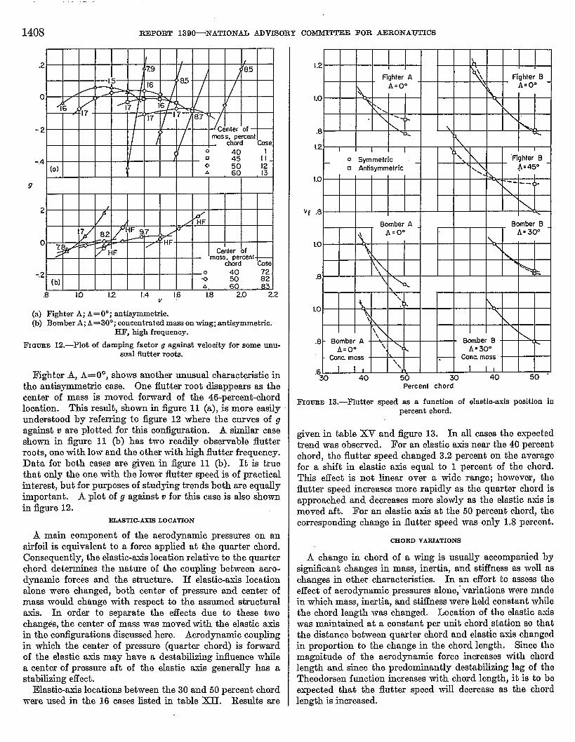
1408 REPORT 139~NATIONAL ABV180RY COMMITTEE FOR AERONAUTICS
2 /
/ / ~F
0 78 Celter ofmoss, percent
chord ~
-.2 40
(b): m. zA 60.
.8 If) 12 1.4 16 1.8 2.0 22v
(a) Fighter A; A= O*; antiaymmetric.(b) Bomber A; A=30°; concentrated mass on wing; antieymmetnc.
HF, high frequency.
FmunEI12.—Plot of damping faotor g against velooity for some unu-sual flutter roots.
I?ighter A, A= O”, shows anothar unusual characteristic inthe antisymmetric ease. One flutter root disappears as thecenter of mass is moved forward of the 46-pereent+hordlocation. This result, shown in figure 11 (a), is more easilyunderstood by refexring to figure 12 where the curves of gagainst v are plotted for this configuration. A similar caseshown in fi=~e 11 (b) has two readily observable flutterroots, one with low and the other with high flutter frequency.Data for both msea me given in figge 11 (b). It is truethat only the one with the lower flutter speed is of practicalinterest, but for purposes of studying trends both are equallyimportant. A plot of g against o for this ease is also shownin figure 12.
~TIGAXTS LOCATION
A main component of the aerodynamic pressures on anairfoil is equivalent to a form applied at the quarter chord.Consequently, the elastic-axis location relative to the quarterchord determines the nature of the coupling between mro-dymunic forces and the structure. If elastic-axis locationalone were changed, both center of pressure and center ofmass would change with respect to the assumed stz-uctumdaxis. In order to separate the effects due to these twochanges, the center of mass was moved with the elastic axisin the configurations discussed here. Aerodynamic couplingin which the center of pressure (quarter chord) is forwardof the elastic axis may have a destabtig influence whilea center of pressure aft of the elastic asis generally haa astabting effect.
Elastic-axis locations between the 30 and 50 percent chordwere used in the 16 cases listed in table lCU. Jkndts are
Vf
1.2 h,I I I #
Fighter A\\ Fighter B
Amo” \ AEOO
Lo\ . \N,
\ ---f ~ \
.8\
-%
L2 I I I \ \ I
O Symmetric \ ‘fighter 8
❑ Antisymmetric\
\\ An 45”
Lo L.--- ._ 1-\
.8 \
Bomber A 8mnbar B
\ Aso’= AS 30’
LO\
\ \\
\\
B \\
\
\\
LO\
\ \ \\
.8 - Bomber A\ \ Banber B \
A=OO\ k A=300
Cane moss \\
ConC moss
I I \.6 I I I I
xl 40 50 m 40 50 ‘Percent chord
FIG~E 13.—Flutter epeed as a function of elastio-axh position inpercent chord.
given in table XV and figure 13. In all ea.seathe expectedtrend was observed. For an elastic axis near the 40 percentchord, the flutter speed changed 3.2 percent on the averagefor a shift in elastic axis equal to 1 percent of the chord.Tti” effect is not linear over a wide range; however, theflutter speed increases more rapidly m the quarter chord isapproached and decreases more slowly as the elastic rmisismoved aft. For an elastic axis at the 50 percent chord, thecorresponding change in flutter speed was only 1.8 percent.
CEORDVARIATIONS
A change in chord of a wing is usually accompanied bysignihnt changes in maas, inertia, and stifhess as well aschanges in other characteristic. In an effort to assess thoeffect of aerodpamic pressures alone,.variations were madein which mass, inartia, and stiffnesswere held constant whilethe chord length was changed. Lccation of the elastic misw-asmaintained at a constant per unit chord station so thatthe distance between quarter chord and elastic asis changedin proportion to the change in the chord length. Site themagnitude of the aerodynamic force increases with chordlength and since the predominantly destabtiing lag of theTheodorsen function increases with chord length, it is to beexpected that the flutter speed will decrease as the chordlength is increased.

INCOMPRESSIBLE FLU’M’ER CHARACI’ERISTICS OF FUIPRESENTAT~ AIRCR.AIW WTNGS 1409
1.4
Q $Fighter A y
1,2A, ~
\
1.0
\B D
q ‘\\
J\\
b h\
\\\
12 \
\\+ fighter B ~
1 IBomber B
A=300Ccmc. moss
1.0
2 \
8 \ \\\ \
\ \I I ‘Q
.5 “ [.0 mPer utit ‘%sic cho~ length
1.5
FrQURE 14.—Flutter speed as function of chord lengtlL
Four configurations were studied in which the chord
length was changed by factors of 0.67 and 1.50. The eightcrises and the con@gurations are listed in table ~. Flutterclmrncterietics are given in table XV and figure 14. Theresults are remarkably uniform. On the average, a 7-percentchange in flutter speed results horn a 10-percent change inchord, smaller chords giving a higher fluttw speed.
SWEEPBACE
The effect of sweepback upon flutter speed depends uponmfmy factors. In conventional wing design, the rootstructure varies greatly with sweepback angle, and theequivalent elastic axis may show considerable variation inposition. J?or wings of large sw-eepback angle and low-rispect ratio, the concept of an elastic axis may not be usefulin describing structural properties. From another point of
view the problem is even more perplexing since there is notgeneral ngreement about the nature of the aerodynamicforces on a swept wing. In the section of this report entitledWinite-Dtierence Errors” the results of three methods ofcomputation were compared with results of wind-tunneltests of a model wing which was sweptback 34.5°. ‘hvomethods were found to give similar results, which weresignificantly better than those of the third. Although thengreement was not entirely satisfactory, it was decided to
use the aerodpamic forces recommended in reference 6.l?or the present investigation, the following assumptions
were therefore made:(1) Aerodynamic forces are as disc&ed in the section
entitled “l?inite-D~erence Errors.”(2) To achieve a sweepback angle, the wing is rotated
about a verticnl axis through the intersection of the unsweptelastic axis and the side of the fuselage. The tip is, however,terminated parallel to the airetream so that only the spanmeasured along the elastic axis is unchanged in length.
(3) Stwctural properties of the wing are unchanged bysweepback.
1.2 1.2
Fightq A fighter B1.0+ 1.0 r(
-o- ~ ~ /t \
\ / ‘\ - “ 4
.8 .8 . 1
\ / ‘ ./
/’3’
.6 12
P1.8
0 Symmetric / ‘“f BomberB
❑ Anti5ymmetricLO(L
\ +
1.6 / -9
x .
/ 8
1.4 1.4
/ %mher A
1.2 / Cam moss1.2
i%mber BCor!c moss 7.
/
KY / 0 /
/ ‘“ - r
/
–- fl’
“
\
\.8 /. - - .8
0 25 500 25 50Sweephck ongle, ~ deg
I?mxmE 15.—l?lutter speed as funotion of sweepbaok angle
(4) The center of mass of the fuselage is moved aft as thesw-eepback angle is increased so that it coincides roughlywith the center of pressure of the wing.
(5) No modifications were made for aerod.yntic forcesat the tip.
The five basic configurations.are shown in table XII, whichgives reference numbers for the 17 cases. The results aregiven in table XV and @ure 15. Flutter characteristics ofthe two iightarsshow a reasonable correlation, and, in general,a decrease in flutter speed for sweepback angles other thanzero. However, the bombws do not show a correlation withthe fighters or with each other. It is significant that a sub-stantial change in flutter speed with sweepback angle wasobserved. In one case, flutter speed increased more than60 percent for a 45° sw-eepback,while other cases showed a30-percent demease for sweepback angle of about 25°.
In addition to the cases above it is possible to crossplot thevariation of flutter speed with sweepback angle for the follow-ing parameter vtiations of bomber B: Wing mass density,wing pitching inertia, bending rigidity, tomiona.1rigidity,and center-of-mass location. hIost of these are plotted infigure 16. It is interesting to note that the general trendfor bomber B is to a great extent independent of these varia-tions.
CONCENTRATED-MASSPIT-Q PLEXIZ_
The engines on .presenkday bombers are sometimesmounted in nacelles on pylons some distance below the wing.
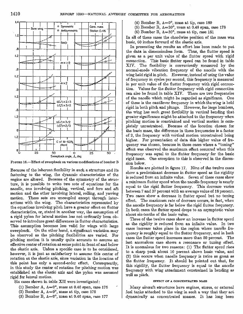
1410 RDPORT 139&NA’ITONAII ADVTSORY COMMITTEE FOR AERONAUTICS
1.4 I I I I Io symmetric
Sore wingGm-Crrlms
o Antisymmetti Station 0.46
1.2 I /A /
~.”t- — - -r S@c / .s’( / ‘
1- ~ -‘ ---- .-
.8
1.2/ /
1 S- . I
(d 7~
mxl12~ .-o-- --
-- --- ( --- ---- .-
.8
I .2/
>/ I#
( mx2 (/
I—
.8/
1.2 /
.“’ I P
~ (GJ) X2/3..
<~ ~ c- ”.. .. n---- --- (1.!7)x312 ‘~ - -=-
.8 II
1.2/
m I#- I
(GJ)x3/2-
---(H)x2i3 ‘ - I --- --- -
8 I I I k,D 7
1.2 ?- 1 I I /.L I I ~// 1
/ ~ ~.(/ --- ---
8 I I I I I Ill0 25 50 ‘o 25 50.
%ee@d( arqle, A, deg
FICJUED 16.—Effeot of Svi’eepbaokon various modifications of bomber B
Bemuse of the inherent flexibility in such a structure and itsfastening to the wing, the dynamic characteristics of theengine are altered. Because of the symmetry of the struc--ture, it is possible to write two sets of equations for thenacelle, one involting pitching, vertioal, and fore and aftmotion and the other involtig lateral, rolling, and ymvingmotion. These sets are uncoupled except through inter-actions with the wing. The characteristics represented bythe equations involving pitch have a greater effect on fluttercharacteristics, or, stated in another way, the assumption ofa rigid pylon for lateral motion has not ordinarily been ob-served to introduce great differences in flutter characteristics.This assumption becomw less valid for wings with largesweepback. On the other hand, a eigniiieant variation maybe observed as the pitching flexibilities are vaxied. Forpitching motion it is usufdly quite accurate to assume aneffective center of rotation at some point in front of and belowthe elastic ati. Unless a speeiiic case is to be ccwzidered,however, it is just as satisfactory to assume this center ofrotation at the elastic axis, since variation in the location ofthis point has only a seccnd+rder effect. Consequently,in this study the center of rotation for pitching motion wasestablished at the elastic axis and the pylon was assumedrigid for lateral motion.
Six crisesshown in table XII were investigated:(1) Bomber A, A= O”, mass at 0.46 span, ease 176 -(2) Bomber A, A= O”, mass at tip, &se 179(3) Bomber B, A= O”, mass at 0.46 span, wise 177
(4) Bomb~ B, A= O”, mass at tip, case 180(5) Bomber B, A=30”, mass at 0.46 span, case 17S(6) Bomber B, A=30°, maw at tip, cam 181
In all of these cases the chordwise position of the mass wrIsbasic, 60 inches forward of the elastic axis.
In presenting the results an effort has been made to putthe data in dimensionless form. Thus, the flutter speed isgiven as a per unit value of the flutter speed with rigidconnection. This basic flutter speed can be found in table~. The flexibility is conveniently measured by thenormal-mode vibration frequency of the nacelle with tlmwing held rigid in pitch. However, instead of using the valueof frequency in cycles per second, this frequency is measuredin per unit value of the flutter frequency with rigid connec-tion. Values for the flutter frequency with rigid connectioncan also be found in table XIV. There are two frequenciesof the nacelle which might be regarded M significant. Oneof th~e is the cantilever frequency in which the wing is heldrigid in both pitch and plunge. However, for large bombors,the wing has such great flexibility in vertical bending thatgreater significance might be attached to the frequency whenpitching motion is constrained and vertical motion is com-pletely unrestrained. Because of the location chosen forthe basic mass, the ditlerence in these frequencies is a factorof 2, the frequency with vertical motion unrestrained beinghigher. For presentation of data this higher value of fre-quency was chosen, beeause in those cases where a “tuning”effect was observed the maximum effect occurred when thisfrequency was equal to the flutter frequency for the basicrigid mass.. One exception to this is observed in the discus-sion below. .
Results are plotted in figure 17. IVineof the twelve casesshow a predominant decrease in flutter speed as the rigidityis reduced from an iniiuite value. Seven of these cases showa minimum flutter speed when the nacelle frequency is nearlyequal to the rigid flutter frequency. This decrease variesbetween 7 and 37 percent -withan average value of 18 perccmt.TWO cases show a decrease in flutter speed but no tuningeffect. The maximum rate of decre~w occurs, in fact, whenthe nacelle frequency is far below the rigid flutter frequency.In both cases the flutter speed drops to an asymptotic valueabout six-tenths of the basic value.
Three of the twelve cases show an increase in flutter speedas the rigidi@ is reduced from an tite value. In twocases incxease takes place in the region where nacelle Irc-quency is roughly equal to the flutter frequency, and in botl]cases the flutter speed increases more than 60 percent. Tholast anomalous case shows a resonance or tuning effect.
It is anomalous for two reasons: (1) The flutter speed risesto a sharp peak about 10 percent above basic value, and(2) this occurs when nacelle frequency is twice w great asthe flutter frequency. It should be pointed out that, forthis rigidity, the flutter ilequency is equal to the nacdlofrequency with wing attachment constrained in bending aswell as pitch.
EFFECTOF ACONCENTRATEDMMS
Nhny aircraft structures have engines, stores, or externalfuel tanks attached to the wing in such a way that they rLctdynamically as concentrated masses. It has long been

INCOMPRESSIBLE FLUTTER CHARACKWLISTICS OF Ii13PRESENTATrfm AIRCRAIW WINGS 1411
1.2
l.o
.8
,6
1.2
10
.8
.6
1.2
I.o
.8
~rI ,6
$/+
(a) Mass at 0.46 span.(b) Mass at tip.
FXWJIUJ17.—Flutter speed as a funotion of ooncentmted-masspitching frequency.
known that the location of such a mass has a significanteffect on flutter. Unfortunately, other aerodynamic andsome structural problems do not permit location of such amass so that maximum flutter speed is obtained. On theother hand, within the redrictions imposed by other con-
~siderations, it is often possible to improve flutter character-istics significantly by proper choice of mass locations.
This investigation has included a detailed examination ofthe eflect of a concentrated mass on the flutter character-istics of several configurations of the four basic airplanewings. Preliminary study of this effect showed such interest-ing and unusual effects that the scope of the in-wstigationwas eqmnded beyond that originally proposed. The result-ing data are so voluminous that it is d.iflicult to present themeffectively. In particular, it is impractical to wmstkct atable which gives all of the data obtained, and so graphicalpresentation is required. Two methods have been ~doptedin this report. For a given spamvise location of the mass,the flutter speed can be plotted as a function of the chordwiselocation. This has been done for all cases investigated.Since the concentrated maw is alined with the airstresm, itis most convenient in caseswith sweepback to move the maw
parallel to the airstrwm rather than perpendicular to theelastic axis. Where suilicient data are available, these curvescan be summarized in a single diagram in which lines ofconstant flutter speed are shown on a drawing of the wingplan form. For the concentrated mass located anywhere onsuch a contour line, the flutter speed will be the same. Theresult is essentially a topographic map of the flutter-speedsurface, where each point on the plan form represents apossible location for the concentrated mass.
Several d.ifiiculties arise with both methods of presentation.The main source of difficul~ lies in the fact that severalimportamt flutter roots exist for a wing with concentratedmass.. For certain locations of the mass, one root will showlowest flutter speed, while for other locations another rootwill have the lowest flutter speed. Since the analog com-puter is essentially an electical model, it is usually impossibleto fmd one of these flutter speeds if another root has a flutterspeed far below the tit. It is possible, therefore, to find withcertainty only those portions of a given -flutter-root surfacewhich lie beneath all other flutter-root surfaces. For oneconfiguration studied, four such distinct surfaces were posi-tively ident%ed and it was not possible to establish thatsurfaces appeaxing at widely separated regions were or werenot related. In most cases the roots were dillerentiated byobttig essentially marginal stability for two distinct rootsalong the line where the two surfaces intersect. It can bereadily appreciated that many points are required to establishthe flutter-speed contours, particularly where several inter-secting surfaces are ihvolved. It was, in fact, impossible inthe time available to obtain sufficient data to establish allinteresting features about these contoum. However, it isbelieved that all important features are shown correctly inthe figures presented here.
The curveEwhich show flutter speed as a function of chord-&e position at a iixed span frequently show intersectionsbetween diilerent flutter roots. In identify@ these roots,it is useful to know the flutter frequency associated witheach root. The simplestway to present these data is to showthe value of frequency at a few selected points along eachcurve. Where roots intersect and both frequencies weremeasured, both values are shown. In some cases whereactual-frequencies were not measured, low, medium, or highfrequency is indicated.
For convenience the concentrated mass was placed at thecenter of a finite-dillerence cell except in three cases whereadditional information was obtained by placing it halfwaybetween cells. It is convenient to identify these locationsby the cell number as has been done in table ~, whichassigns a case number tw each contlguration. It must beremiimbered, however, that the cell diviions are slightlydiflerent for bomber and fighter airplanw, and therefore thespanwise station for a given cell number will be different.The location of these stations in terms of unit span is givenin table XHI. In the figures, the spanwise position is cor-rectly given as a fraction or per unit value of the wing semi-span.
The size of the concentrated maas and its pitching androlling inertia also af?ect the flutter speed. Since past experi-ence has shown that rolling inertia has a small effect, a few

1412 RDPORT 139@NATIONAIJ ADVISORY COMMITTER FOR AERONAUTICS
cases were chosen for further investigation of the magnitudeof this effect. For a concentrated mass located in the tig.it is reasonable to assume a radius of gyration which is asmall fraction of the average half chord. For a mas sus-pended below the wing it is unI&ely that the distance wilIexceed half of the average half chord. Two radii of gyrationequal to 0.1 and 0.5 timm the average chord for the fighterplanes were chosen. In all cases considered there was nosignificantt difference in flutter characteristicswhen the rollinginertia was varied from zero to the maximum value. Thevariation was, in fact, so insignificant that none of the datais presented in this report. In what follows it may be as-sumed that the rolling inertia of the concentrated mass hasany value between the above limits. Since the mass of theconcentrated mass and itq pitching inertia have a greatereffect, it is necessary to consider variations in these quan-tities in several typical cases. The basic values for mass andpitching inertia (or radius of gyration k) have been discussedin the section entitled ~(Charactaistim of Tour Representa-.tive Aircraft” and are given in table ~. The variationsof these values are summarized in table XCV.
!J%8 most logical W&y to give the redts is to presentfirst the flutter characteristic for the basic m- on eachparticular airplane. J?ive airplanes were chosen:
(1) I?ighter ~ A=OO(2) Fighter A, A=45°(3) Bomber A, A=oO(4) Bomber B, A=OO(5) Bomber B, A=30°
It was di.tlicult to choose a typical radius of gyration for amass on a fighter plane. The values used, 6, 15, and 30inches, are shown in table ~. l?igures 18 (a) and 18 (b)show the effect of chordwise location of the mass at fivespamvise positions for fighter A with A= OO. Results forall three radii of gyration in pitch are plotted on the samesheet using difkrent symbols for each value. Circles areused for the smallest value, k=6 inches; triangles are usedfor k=30 inches; a solid line with no symbols is used forthe intermediate value. Abscissas for all curwx are chord-w-ise distance from the elastic axis measured as per unitvalue of the wing semispan. Similar data for fighter A,A=45°, are shown in figures 18 (c) and 18 (d); six spanwisestations were used in this cme. One surprising feature canbe noted in all of these figures: The characteristics arerelatively independent of the pitching inertia, even thoughthis inertia is varied from a very large value (k=30 inches)ta nearly zero (k=6 inches). This does iot mean that atany particular point the flutter speeds are identical, but theoverall shapes of the curves are remarkably similar.
Although these figures (iigs. 18 (a) to 18 (k)) give a goodpicture of the flutter characteristics, it is easier to interpretthe results if all data are combmed to construct flutter con-tours as discussed edier. Such contours for the minimumand maximum values of k are shown in figures 19 (a) to19 (h). Th~e figures support the following conclusions:
(1) A chordwise position aft of the elastic axis is almostalways undesirable.
(2) The 30- to 50-percen&spanposition and the tip locationare generally und&rable.
(3) A position forward of the elastic axis and mmr tho 70-to 80-percent-span position will, in general, greatly increasethe flutter speed. f
Siice time did not permit a complete study of the charac-teristic for fighter B, data were obtained only for the casesof 0° and 45° sweepback with mass at the tip. Compmisonof the results shown in figure 18 (e) with the correspondingdata for fighter A in figures 18 (a), 18 (b), 18 (c), and 18 ((l)shows that for this location there does not seem to bo anysignificant difference in chara@ristics. Whether it is safeto extrapolate this result to other mass locations ca~notbe said at this time.
..
1.2
1.0
8
.6
4
1.6
L4
1;2
1.0
8
61 I I I I I I I I I I I II I
1.6
1.4
1.2
T Lo
.8
.6
4
1.2 1/
12, I u -_ * 17-1.0 /
.8 // /
6 _ ~ ,/ ./Swl PJsition,0.50
/ 10 case4 0 184
2❑ 185
1.6
1.4
1.2Ig1.0 13 ~
8 ‘Spca pxl!lon, 0.36
Acase
6q (o)
O 182~ [83
-.2 -.1 0 .1 .2 3 4 .5
/
Chordwise position
(a) FigMer A; A= O”; symmetrio.
FIGURE18.—Flutter oharacteristia agaimt crhordwieeposition of con-centrated rows. HF, high frequency; MF, medium frequemy;LF, low frequenay.
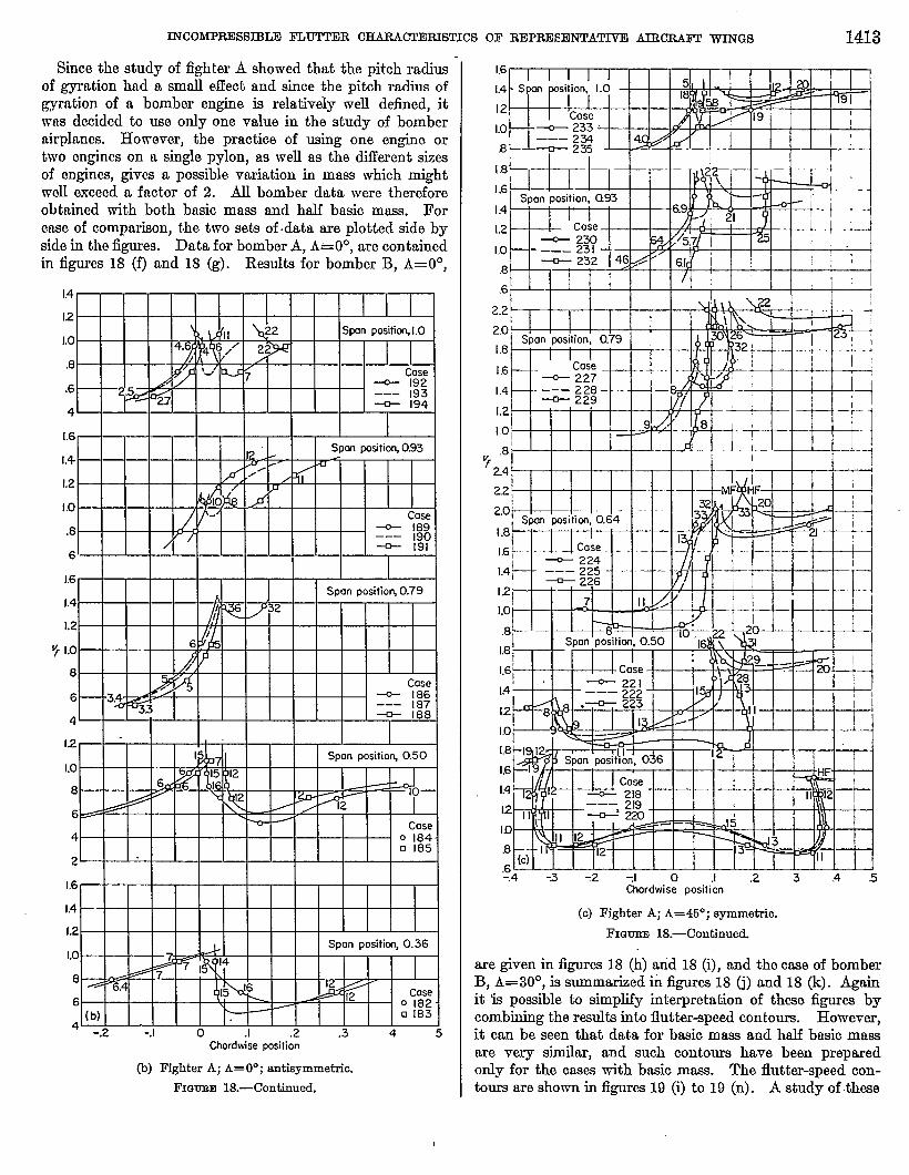
INCOMPRESSIBLE FLU’JTJ3R C!HARACTEFUSTICS OF REPREH3NTATIV13 AIRCRAFT WINCH 1413
Since the study of fighter A showed that the pitch radius -of gyration had a small effect and since the pitch radius ofgymtion of a bomber engine is relatively well defied, itwas decided to use only one value in the study of bomberairplanes. However, the practice of using one engine ortwo engines on a single pylon, as well as the diiferent sizesof engines, gives a possible variation in mass which mightwell exceed a factor of 2. All bomber data were thereforeobtained with both basic mass am-l half basic mass. Forease of comparison, the two sets of data are plotted side byside in the figures. Data for bomber A, A= O”, are containedin figures 18 (f) and 18 @. Results for bomber B, A=OO,
1.4
12
.8
.6
4
1,6
1.4
1.2
1.0
.8
6
1.6
1.4
1.2
y 1,0
8
6
4
12
Lo
8
6
4
2
1.6
1.4
1,2
Lo
8
6
4-.2 -.1 0 .1 .2 .3 4
Chmdwise @tion
(b) Fighter A; A= O”; antisynunetric.
FIGURE 18.—Continued.
1.6
1.4
12
1.0
B
1.4i j 1 II I I I I%b?%l--q I
1.2
-r
Cose I / I 1~ 230 -% ,, .1
1.0 –—– 231~ 232 1;11
.8 R -- ./l I
c,II.-
2.2
20
1.8111111
1,6
I.4-H--R++
1.2
I,0
.8? 24
22
20
1.8
1.6
1.4
12
1.0
.8Y-’--F+
1.8
16
L4
12
1.U[.81.6
1.4
12
15)
.8
,n!LLm-k--l Jll
I I 1 I 1 I I I.61 “-”1 I I I I I I I I I L-.4 -3 -2 -J o J .2 3 .4 .5
Chordwise position
(c) Fighter A; A=46”; eymsnetriu.
FIGURE 18.—Continued
are given in figures 18 (h) wid 18 (i), and the case of bomberB, A=30°, is summwized fi iigures 1S (j) and 18 (k). Againit b possible to simplify interpretation of these figures bycombining the results into flutter~peed contours. However,it can be seen that data for basic mass and half basic massare very similar, and such contours have been preparedonly for the cases with basic msss. The flutter~peed con-tours are shown in figures 19 (i) to 19 (n). A study of these

1414 REPORT 1390+NATIONAII ADVISORY COMMTITEE FOR AERONAUTIC
22
2.0
1.8
1.6
1.4
1.2
I .0
.8
G
2.6 I I
2.4
22
2.0
1.8
1.6
I .4
1.2 I 1 F /- u..
I .0
I I I I.8 I I I
2.4
2.2
20
1.8
1.6
1.2 I I -r n
Lo
.8
1.4
2.4
22
20
1.8
1.6
.4
12
1.0
.8 .-ChcOdwise position
(d) Fighter A; A=45”; antisymmetric.
I?mmRE 18.—Continued.
figures shows some deviations from the results for fighterairplanea. The following conclusions can be drawn:
(1) A position aft of the elastic axis is almost alwaysundesirable.
(’2) The tip region is generslly und~able as a locationfor the mass.
(3) With few exceptions, any position forward of theelastic axis and between the root and the 90-percent-spanposition will give flut@r speed equal to or greater than thebare-fig flutter speed.
(4) There are, in most cases, no practical locations whichgive any significant improvement in flutter chnraoteristics.Two csses will be noted in which the speed might be incrensed40 percent. The others are restricted to a 10- or 20-percentimprovement.
Site fighter planea showed remarkable variation influtter characteristics with mass position, it was believoclto be necessary to examine the effect of changes in the size(mass) of the concentrated mass. This wm fit studied attwo spanwise positions for fightar A, A=OO. The positionsare the tip and station 5 (0.79 span). Flutter charactetiticsm functions of chordwise position were mensured for severalvalues of mass. The three values of radius of gyrationgiven in table XIII were used for all mass values, exceptthat for very small values of mass only the 6-inch value was
2BS* @tion, 0.50 I
Ccse--- A . .2.4 1’
Vf
8 I I I I I 1 1 1 I 1 1 I 1 I
I I I I I I I
“ Ou-Ai
1.5
1 I I I I I I I I I I I I
2.0 I I I
I I I I I I I II I I I I Case.
I I ~ 245
I I I I-.
Brl.--. 246 —
la! \~ 247 —
Cixxdwii @ticm
(d) Continued.(e) Fighter B; data taken at tip.
FIGURE 18.—Continued.

lNCOMPlUM3SlBLE FLUTTER CE4RACTERISTICS OF REPRE8ENTA- AIECILKFI? ~GS 1415
12
10
8
6
14
12
10
8
6
4
14
12
Lo
8
16
14
12
10
8
V, ,6
1,6
14
12
10
8
14
12
1,0
8
6
4
12
10
8
6
14
12
10
8
6 -.1 0 J .2 -J o .1 .2Chordwise position
(f) Bomber A; A= O”; symmetriu.
FKNJRE18.—Continu~
14
1.2
1.0
.8
6
L6
L4
L2
1.0
.8
6
1.4
1.2
1.0
.8
1.6
1.4
1.2
1.0
.8
‘f .6
1.6
1.4
1.2
1.0
,, .-,,
‘~1 ‘ i-’=i ‘-1-’1.4 t I I
/1.2 IL
%-SDon Posit”m,0.62 ~~ ~
4-
Cose 251
1.0 / I I%8 ~~ 2.59 (... ___
8 /
.6 / II
1.4 I I
1.2 H_..L J%
/I .0
/ Cose 258.8- A 36
1.6I
. . ,- . 1m posit-w 0.31
&J~COse249
. . I i 1-
.sl
I .2 =/
Lo ,J45 1ocose2 .57 nt/1lolJ-----l ljF
(9) 7 /
8L I I I I [ I I 1 1 1 1 ) I 1 I-J o
I.1 .2 -J o .1 .2
Chordwisepositiea
(g) Bomber A; A= O”; antisymmetrio,
~GUEE 18.—Contiiued.

. . .. . .. . . . ___ . . .. .__ .._ __________ ___________ ._. _ . . ________
1416 REPORT 139~NATIONAL ADVISORY COMMTITEE FOR AERONAUTIC%
.1.2
Mass.= 0.5 basic massIll
Mass = Lo bUSiCmassLo I I II I I - 3on px.ition, 1.00 /
n I h3J15I P7 I
Ii}{ll’’ iiik’k’fl”l60
.6 2.2case 275 .5 I ~6 Case 269
I4~ I “
I I I I
1.6
1.4
1.2
1.0
.8
.6
4
1.6
1.4
1.2
1.0
.8
.6
..4W+++i’’l’i’i’1+%? X2
,,
Case267
‘ 1.4
1.2
1.0
.8
6
4
1,6
1.4
1.2
Lo
.8
.6
4
1.6
14
1.2
1.0
.8
.6-.1 0 .1 .2 -J o .1 .2
Chordwise lmsittin
(b) Bomber B; A= O”; symmetric.
FIGURE 18.—Continued.
1.6Mass = 0.5 basic moss I Mass. I.O basic mass I
[.4
L2
Lo8
.6
4
2
1.4
12
8
.6
I.oku—ww+—
4 I I I I I I I
2
1.4
1.2
Lo.8
.6-S o .1 .2 -.1 0 .1 .2
Chafdwise position
(i) Bomber B; A=OO; antisymmetrlo.
FIG- 18.—Continued.
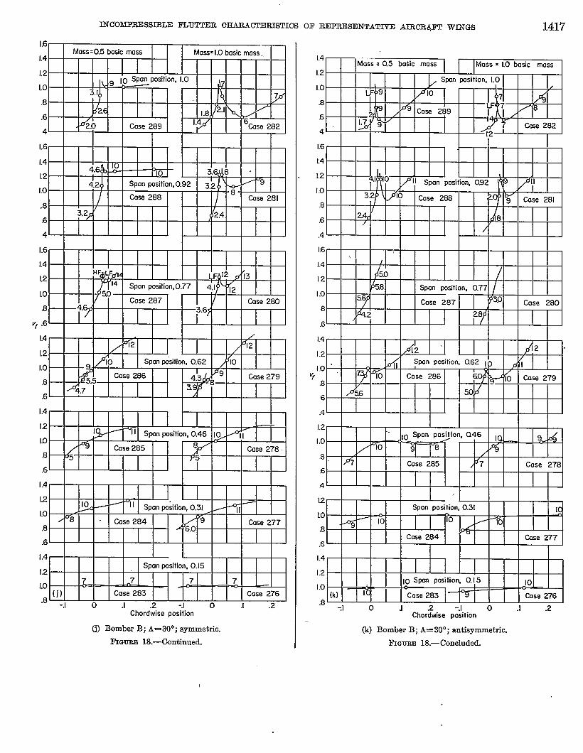
INCOMJ?RESSD3LE FLUTTER CHMZAGLTKUSTICS
L6
L4
L2
Lo,8
.6
4
I I ,.-L2I II I 1 1
1.6
L4a A @ I i
10. 3ti8 “
4.2+ Span position,Lo
II Casa 288 I I I l/lUlCOSS2811
, I ,
,0.92I
3.2
1.6
1,4
1,2
10
.8
V, .6
1.4 I I I I I I / I
[.2
‘~w=d’”’o”’”“0’‘‘‘, ! 1 / I II
Case 2793
.61 j ‘“” I I I I I II I
1.4
1,2
Lo
.8
,6
.4
.6
I,4 ISpan posJtkm, OJ5
1.2
Lo 7 7
,8 (j) Case 283 Case 276
-,1 0 .1 .2 -J o J .2Chordwise position
(j) Bomber B; A=30°; symmetrh.
FIQUIWI18.—Continued.
OF REPRESENTAT~ AIRCR,@l? WINGS 1417
1.4IMass :0.5 ba$ic mass I I l~ass x LO basic mass
1.0
.8
6
4
1.6
L4
1.2
I,0.8
.6
.4
16 \,
1.4 I
,,-, 5s) / , I
I I A I I2.8
1.4I
1,2 AZ ‘ 12 “I / I
II Spw ---’”-- ‘-aI .0 ‘
9. To Cose 286 6Y o
Case 279
6X&6 50.d
Ill pu3411ulhU.oc l(-) Idllll
.4 ‘ I I I I I I I I 1 I I I I I I
1.2
I.0
.8
.6
4
12
LO
.s
.6
1.4 I
1.2 Ill1.0
10 Spare positio~ 0.15 10-
.8 (k) lb— — ~
Cose 283 Cuse 276
-J o J .2 -J o .1 .2Chordwise position
(k) Bomber B; A=30”; antisymmetric,
FIcmnin 18.—Concluded.
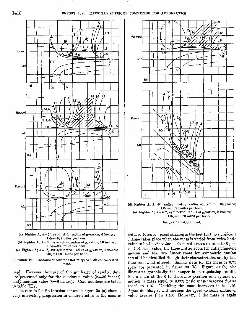
1418
Forwc
i
!=orwo
P
FOw.ur
Ai
REPORT 139&NATIONAL ADVISORY COMMTITEE FOR AERONAUTICS
..-
111 1~
1 1
.6
:b) t.8
7/ ~
I
~8LO
Lo .2
/ \
1.4
1 LO .6 \ ‘t4 . I \\\I l--t--4a--4a- Ill //1 /$ J/Jl
II 1 l\ \l l\A II If’//
II t4
I I f ~- 1 1lllw=--LL44w-/ I
I i I ‘V17J4 i
:C)I
(n) Fighter A; A= O”; cymmetrio; radius of gyration, 6 inches;1.00J=989 miles per hour.
(b) Fighter A; A= O”; symmctrio; radius of gyration, 30 inches;1.00j=989 miles per hour.
(c) Fighter A; A= O”; antisymmetric; radius of gyration, 6 inches;l.OOfU1,091 miles per hour.
. FIGURE 19.—Contoum of c.onatant flutter speed with concentratedrows.
w@. However, bemuse of the similtity of results, dataare”’presented oily for the mnsimum value (k=30 inches)
‘minimum value (k=6 inches). Case numbers are listedundwin table ~.
The results for tip location shown in figure 20 (a) show nvery interesting progression in characteristics as the mass is
‘a word
Aft
Fonvard
Aft
(d) Fighter A; A= 0°; antiaymmetrio; radius of gymtion, 30 inohw;l. OtJf=1,091 rnika per hour.
(e) Fighter A; A=45”; symmetna; radius of gyration, 6 inohcs;l,OOJ=1,028 miles per hour.
l%URE 19.—Continued.
re(lucecl to zero. hlost striking is the fact thnt no significantchange takes place when the mass is varied from twice basicvalue to half basic value. Even with mass reduced to 8 per-cent of basic value, the three flutter roots for antisynmmtricmotion and the two flutter roots for symmetric motioncan still be identtied though their characteristics are by thistime somewhat altered. Similar data for the mass at 0.79span are presented in figure 20 (b). Figure 20 (I-L)alsoillustrates gmphicdly the danger in extrapolating rcaults.For a mass at the 0.10 chordwise position and symmetricmotion, mmass equal to 0.008 basic mass incremes flutterspeed to 1.07. Doubling the mass increases it to 1.16.Again doubling it will increase the speed to some unknownvrdue greater than 1.4o. However, if tho mass is ngnin

12TCOMHLE881BIJ13FLUTTER CHARA~RISTICS OF REPREV31JNTATIVEAIRCRAFT WfNGS 14-19
Forword
Aff
Aft
I I I i.o
m
(f) Fighter A; A=45”; symmetrio; radius of gyration, 30 inches; .l.OOJ=1,028 miles per hour.
(g) Fighter A; AU450; antisymmetric; radiue of gyration, 6 inohea;1.0uf=881 miles per hour.
FIGURE 19.—Continued,
Forvmrc
Aft
Frnwm
Af
Foiwon
Af
Vf12
I I I I1 I 1 1 I t f
II A 1=0\I II [l(\l\
I f//
L
.6\
‘.8(i)
.4\
1,
A L4.
/ /.8
(j)
(h) Fighter A; A=45”; antiaymmetric; radius of gyration, 30 inches;1.0uj=881 miles per hour.
(i) Bomber A; symmetrio; 1.0uf=818 miles per hour.(j) Bomber A; antisymmetrio; 1.00,=S86 mib per hour.
I?IGURE 19.—Continued,

.-—. . ..—. . ..- —..--——— ———
1420
Fonvord
Aft
Forword
Aft
Forword
Aft
Forword
Aft
REPORT 139&NKITONAL ADVISORY COMMI’M’EEl FOR AERONAUTICS
1 \
\, ,(1/ l.o~II I I
I 4
(1) I9
L2
I\
\.1.4II
1 1 1 I I \ 1 I
I I I I
INY l\\lk I I
k!iO%%IQRk.J J4 ‘fj~
H 171%i-aw& +j .8‘.
[rn)ll ~ I I ‘1= I(II .8 I I
‘T~1
=%.:
\ I
.y
Lo 17. .
7
II .8
I
\
1 1= I 1 1
(n)
(k) Bomber B; symmetric; l.OW=I1,216 miles per hour.(1) Bomber B; antiaymmetric; l.OOJ=1,216 miles per hour.(m) Bomber B; symmetia; 1.OU,=1,165 milsa per hour.(n) Bomber B; antisymmetric;. 1.0DJ=1,244 rnik per hour.
FIQUEE 19.—Ccmcluded.
I
I
‘1
1.2
Lo
.8
.6
.4
1.2
Lo
.8
.6
1.4
12
V’j 1.0
.8
.6
I .4
1.2
1.0
.8
.6
.4
1.4
1.2
1.0
.8
.6
1.2
Lo
.8
.6
1.2.1.0
B-1 “o .1 .2 -.1 o .1 .2
Chordwise position
(a) Concentrated mnm at tip.
FIGURE 20.—Effect of size of concentrated mw on fluher ahnrnotor-istics. Fighter A; A= O”.
inoreased by a-factor of about 2.8, the flutter speed (ofanothar root) will have dropped to 1.00 again.
Flutter characteristics were also measured for baaic andhalf basic mass at the wing tip with sweepback angle of 46°.This case was chosen because the antis~etric character-istic for a 30-inch radius of gyration (fig. 1S (d)) showed o
INCOMPRESSIBLE FLUTTER CHARACTERISTICS OF RDPRESENTATIVTI AIRCRAET WINGS 1421
8 I I
.6
1.61412
Lo
1.2
5 ,,.8 COse / -.6
I0 2150217 (b)
93 -.2 -.1 0 .1 .2 -.2 -I o 1 2Choiwisepitbn
(b) Concentrated mae9 at 0.79-span position.
FIGURE 20.—Concluded.
very unusual characteristic. l?igure 21 (a) shows that reduc-
tion of the mass by a factor of 2 eliminates the anomalous
behavior, but in all other respects gives results which areessentially the same as the basic mass. J1’igure 21 (b) gives
similar data for the maw at the 0.79 span position with A=45°. Agdin the results for basic mass and half basic mass arenot signi6cantly cWerent. It is perhaps untie to attempt
any general statement, but there is every indication that the
essential features shown in the flutter-speed contours offigure 19 would not be profoundly altered if either mass orpitching inertia were increased or decreased by a factor aslarge as 2,0.
ACCURACY AND PROBABLE ERRORS
It is believed that a discussion of the expected accuracyof the results will be more meaningful now that the reader hasobserved the nature and scope of the data obtained. Theanalog computer is not composed of perfect electricalelements. For example, the inductors used in this studyhave lose characteristic corresponding to a damping factorof about g= O.01. Transformers also have signifkant loss-w..The electrical analog of the airplanes studied in this reporthad an electrical damping corresponding to a structuraldamping between g=O.02 and g= O.03. This is not greatlydifferent from the damping to be found in conventional&craft construction, so no corrections were made for thisinternal damping.
No general statement can be made about tle effect ofrandom computer errors. Some give rise primarily to anerror in the damping factor of the roots, in which the &o)curve is shifted vertically. Other errom give rise basioallyto cm error in velocity, in which the curve is primarilyshifted horizontally. Since the slope of the curve of gagainst u is by no means constant, it becomes impossibleto give a speciiic figure for accuracy of flutter speed. Inunusual cases, where roots are of thp type shown in figure 12,flutter may be predicted when in fact it will not occur forthese roots at all. This distinction, which must be mademathematically, is of no importame in practical cases. Anairplane which shows a flutter damping of g= 0.01 and istherefore theoretically stable is not to be regarded as anymore satisfactory or useful than one which shows a damping
g= —0.01 and would therefore theoretically fly apart.Manufacturing tolerances and the safety factom required inaircraft will not permit use of an aircraft unless it is moder-ately stable for a significant variation in all structuralparameters. It is believed that, exclusive of errors intro-duced by the fite-difference structure and approximationsin the aerodynamic theory, the results obtained in this studyhave a probable error in damping factor of about g= +d.02or a probable error in flutter speed of about 2 percent, whioh-eve.ris applicable in the light of the above discussion. How-ever, trends obtained by variation of structural parametersare considerably more accurate than this would imply,since any error would persist with roughly the same value inall oases involving such parameter variations.
For cases 1 to 181, it is p’ossible to construct curves of gagainst o although they have not been made a part of thisreport. These curves serve to show the steepnesswith whichthe roots pass through flutter and give some indication of theaccuracy of the flutter speed. This situation does not existfor cases 181 to 289. For concentrated-mass variations,
20
Vf I.5
0
2.0
Vf 1.5.
0
-J o .1 .2 .3 -. I o .1 .2 .3 .4Chordwise IXSiticm
Vf
Vf
2.0
1.5
0r 1 1 I 1 1 1 1 1 I I ! 1 1 1
1 JI R%/’l I I
L5
oI 1 . .
1
-.1 0 .I .2 -.1 0 .1 .2Ctwrdwise @tion
(a) Basic mace and 0.5 baaio mass at tip.(b) Baaio mwm and 0.5 baeio mass at 0.79-epan positiom
FIGH 21.—Compsmiscm of oharacterietice for basio maes and 0.5
basio mass. Fighter A; A=45”.
1422 REPORT 139@NATIONAL ADVISORY COMMI!M?EE FOR AERONAUTICS “
computations were carried out in such n way that only flutterspeeds and frequency were obtained. Consequently, it isnot possible to delineate areas which. are “safe” from thestandpoint of flutter. It is lmown, for example, that wherea long pendant lobe is observed, as for case 235 in figure18 (d), the systim is barely unstable everywhere within thislob,e. There axe similar regions where the system is barelyunstable within an elliptical-shaped boundary, for example,case 212 (fig. 20 (b)). Siiarly, case 214 is barely stablein this region and yet no flutter root is even shown sincethe system does not become actually unstable at any point.
These remarks are not made to show the flutter curvesto be valueless, but to caution the reader against makinginferences not contained in the report and not legitimatelysupported by the data presented here.
SUMMARYOF RESULTS
Certain trends in flutter characteristics for typical modernaircraft seem to be indicated by-this study of the incompres-sible flutter characteristics of aircraft wings. In some ewesa few deviations are found. It is probable that if moreextreme aircraft designs were considered even more wouId beobserved. Nevertheless, this summary may serve as auseful guide.
(1) In the following table are ~sted the average changes influtter speed for a l-percent change in each parameter, thechange being made horn the basic value except for centar-of-mass and elastic-axis location, in which casea severallocations are assumed.
Change in parameter~;z:~
percent
Incr=e wing maf9 1 percent _______________ oIncrww wing pitching inertia 1 percent____ —. 1Increase bending rigidi~ 1 percent --------- 0IncrU toreional rigidity 1 percent --------- 5Increaae wing chord 1 percent -------------- —: 7Center of m= forward 1 percent of chord
from—40-percent lomtiom----------.-------- 3.05@pement lomtiom ------------------- 1.760-percent lowtiom------------------- .8
Elastic axis forward 1 percent of chord froro-40-percent lomtiom ___________________ 3.250-percent lomtioL --------------- ---- 1.8
(2) Imdized change in torsional rigidity is most effectivein changing flutter speed of a bare-wing airplane if thechange is made between midspan and root. For bomberswith large concentrated mass on the wing, torsional rigidityeither inboard or outboard of the maw will usually governflutter speed, depending on the type of flutter existing.%veepback was not observed to have a systematic effect.Pitching flexibility of the concentrated-mass support has adefinite inlluence on flutter speed. In many cases a tuningeffect was observed, with a 10- to 40-percent decrekse influtter speed. This effect ww not always observed; insome cases, the flutter speed was significantly increased.
(3) perhaps the most interesting remdta will be found inthe tiects of a concentrated-mass location. For o widerange of mass and radius-of-gyration values the resultswere very systematic. For fighter-type planes it was foundthat:
(a) Aft chordwise positions are usually undesimblo.(b) The 30- to 50-percent-span and tip locations nro
generally undesirable.(c) A forward location near the 70- to 80-percent-span
position will, in general, greatly increase flutterspeed.
For bomber-type planes these results are somewhat modified:(a) Aft chordwise positions are usually undesirable.(b) The tip location is generally undesirable.(c) With few exceptions any location forward of the
elastic axis and between root and 0.90-span posi-tion is satisfactory, although flutter speed israrely greater than bare-wing flutter speed byany significant amount.
There is perhaps no need to remark that these remdts canbe altered by introduction of a fle.xibfity in the concentrotecl-maw support.
CALIFORNUINSTITUTEOF TECHNOLOGY,PMADENA,CALIF.,June 6’, 19&5.
REFERENCES
1. MacNeal, R. H., MoCann, G. D., and Wilts, C. H.: Tho Solutionof Aeroelastic Probleme by Means of Electrical Analogtcs,Jour. Aero. Sci., vol. 18, no. 12, Dec. 1961,pp. 777-789.
2. Benacoter, Stanley U., and MaoNeal, Richard H.: Introductionto Electrical-circuit Analogies for Beam Analysia. NACATN 2785, 1952.
3. Semll, John L.: Esperirnental and Analytical Invcatigation ofFlutter of a Nonuniform SweptbaokCantileverWing With TwoConcentrated Weights. NACA RM L51H09a, 1961.
4. Nelson, Herbert C., and Tomaesoni, John E.: EsperhnontalInvestigation of the Effeots of Sweepback on the Flutter of aUniform Cantilever Wing With a Variably Loc.atod Concen-trated Mass. NACA RM LLW24,1949.
6. Barmby, J. G., Cunningham, H. J., and Garriok, I. E.: Studyof Effects of Sweepon the Flutter of CantileverWings. NACARep. 1014, 1951. (SupersedesNACA TN 2121.)
6. ScanIan, Robert H., and Rosenbaum, Robert; Introduot.ion tothe Study of Aircraft Vibration and Fluttm. The Macmillanco., 1961.
7. McCann, G. D., and Braham, H. S.: A Study of the Aocumoyof Lumped Parameter and Analog Computor Reproeentationsof. Cantilevered Beams Under Conditions of Statio Stress andDynamio Vibrations. Rep. No. 3, Contraot AF 18(600)-660,Officeof Sci. Res. and C. I. T., 1965.
8. Goland, Martin, and Luke, Y. L.: The Flutter of a Uniform WingWith Tip Weights. Jour. Appl. Mecb., vol. 15, no. 1, Mar.1948,Pp. 13-20.
9. Runyan, Harry L., and Watkins, CharlesE.: Flutter of a UniformWing With an Arbitrarily Placed Maas According to a Dif-ferential-Equation Analyeie and a Qomparieon With E~peri-ment. NACA Rep. 966, 1960. (SupersedesNACA TN 1848.)
10. Wilti, C. H.: Finite DMerence Errors in the Flutter Speed of aUniform Wing With an Arbitrarily Placed Maw. AnalysisLcb. Rep., C. I. T., June 1954.
11. Runyan, Harry L, and Sewall, John L.: E~erimental Investiga-tion of the Effects of Concentrated Weights on Fluttrr Char-aoteriatics of a Straight Cantilever Wing. NACA TN 1604,
.. 1948. “