Embed Size (px)
Citation preview


REPORT DOCUMENTATION PAGE
la. REPORT SECURITY CLASSIFICATION Unclassified
I b RESTRICTIVE MARKINGS
Form Approved Ohltl No. 0704-0188
!a. SECURITY CLASSIFICATION AUTHORITY
!b. DECLASSIFICATION/DOWNGRADING SCHEDULE
3 DlSTRlEUTlON/AVAlLA6lLlTY OF REPORT
Approved for public release; distribution unlimited. I. PERFORMING ORGANIZATION REPORT NUMBER(S)
Instruction Report D-9 I- 1
S. MONITORING ORGANIZATION REPORT NUMBER(S)
ia. NAME OF PERFORMING ORGANIZATION San Diego State University Department of Civil Engineering
6b. OFFICE SYMBOL 7a. NAME OF MONITORING ORGANIZATION (If applicable)
ic. ADDRESS (City, Stdte, dnd Z/PCode)
San Diego, CA 92182 7b. ADDRESS (City. State, and NPCodeJ
la. NAME OF FUNDINGISPONSORING 8b. OFFICE SYMBOL 9. PROCUREMENT INSTRUMENT IDENTIFICATION NUMBER ORGANIZATION (If dppkdbk)
US Army Corps of Engineers Contract No. DACW39-89-C-0036 IC. ADDRESS (City, Stdte, dnd ZIPCode)
Washington, DC 20314-1000
10. SOURCE OF FUNDING NUMBERS
PROGRAM PROJECT TASK WORK UNIT ELEMENT NO. NO. NO. ACCESSION NO.
1. TITLE (Indude Security Classification) I
Program Documentation and User’s Guide: PCDDF89, Primary Consolidation and Desiccation of Dredged Fill
2. PERSONAL AUTHOR(S)
Stark, Timothy D. 3%cAE$g;PORT 13b. TIME COVERED 14. GATE OF REPORT (Yew, Month, ‘?dY) 15. PAGE COUNT
FROM TO- July 1991 92 6. SUPPLEMENTARY NOTATION
7. COSATI CODES
FIELD GROUP SUB-GROUP
18 SU~~~~u~P..~cont&e 0~2t&&$Cessd~ dnf&$@ block number1
Confined disposal Dredged material Consolidation Finite strain
9, ABSTRACT (Continue on reverse if necesswy and identify by block number) The US Army Corps of Engineers has developed a computer program to model consolidation and desiccation that
OCCuls in confined dredged material placement sites; the program is entitled “Primary Consolidation and Desiccation of Dredged Fill (PCDDF).” The program is equally applicable to other soft, fme-gralned deposits. Although originally written for operation on a mainframe computer, the program has been modified to run on an IBM (or compatible) microcomputer with a math coprocessor. It has recently been extensively revised and modified into a more user-friendly version that is referred to as PCDDF89.
This report contains a brief description of the mathematical model used in PCDDF89 and an extensive user’s guide. PCDDF89 simulates the consolidation and desiccation processes in fine-grained soils using the finite strain theory of consolidation and an empirical desiccation model. Settlement is calculated for each compressible layer within the area, and a cumulative settlement for all dredged fill and compressible foundation layers is determined. Additional layers of dredged fill can be added at any time. A total of 25 types of dredged fill and 25 foundation layers can be analyzed in one simulation.
(Continued) 20. DlSTRl9UTlON /AVAILABILITY OF ABSTRACT
~uNCLASS~FIEDIUNLIMITED Cl SAME AS RPT
!2a. NAME OF RESPONSIBLE INDIVIDUAL
,n C1I.B 4 1-m 111.1 OI
21 ABSTRACT SE
0 DTIC USERS Unclasst ed 4 URITY CLASSIFICATION
22b. TELEF +ONE (Indude Ared L&e) 22~. OFFICE SYMBOL
I.. rrevrous eamons dre onsoiete. SECURITY CLASSIFICATION OF THIS PAGE
Unclassified

Unclassified
SECURITY CLASSIFICATION OF THIS PAGE
19. ABSTRACT (Continued).
An interactive interface has been developed for PCDDF89. The interactive data input program, INPCDDF, allows users to easily convert existing PCDDF data files to the new multi-material data format of PCDDWB. The interactive program also allows the creation of new data files and editing of existing files.
SECURITY CLASSIFICATION OF THIS PAGE

PREFACE
This report describes the user guidelines for implementing the one-dimensional microcomputer program, Primary Consolidation and Desiccation of Dredged Fill, 1989 (PCDDF89). PCDDF89 is an updated version of the original program, PCDDF, devel- oped by CPT Kenneth W. Cargill at the US Army Engineer Waterways Experiment Station (WES). Instructions for data input and details about the output are covered herein. The work was sponsored by the Dredging Operations Technical Support (DOTS) Program funded by the Office, Chief of Engineers, through the Water Resources Support Center, Dredging Division. DOTS is managed through the Environmental Effects of Dredging Programs (EEDP) of the WES Environmental Laboratory (EL). Dr. ‘Robert M. Engler was EEDP Manager during publication, and Mr. Thomas R. Patin was DOTS Coordinator in EEDP.
This report was prepared by Dr. Timothy D. Stark at San Diego State University under contract No. DACW39-89-C-0036 with WES. The modifications to PCDDF were coded by Dr. Arsalan Ghahramani, a visiting scholar at San Diego State University, under the supervision of Dr. Timothy D. Stark. Dr. Marian P. Rollings, Research Civil Engineer, Water Resources Engineering Group (WREG), Environmental Engineering Division (EED), EL, WES, was Contracting Officer’s Representative. The report was written under the general supervision of Dr. John J. Ingram, Chief, WREG; Dr. Raymond L. Montgomery, Chief, EED; and Dr. John Harrison, Chief, EL.
The Commander and Director of WES was COL Larry B. Fulton, EN. Teclhnical Di- rector was Dr. Robert W. Whalin.
This report should be cited as follows:
Stark, T. D. 1991. “Program Documentation and User’s Guide: PCDDF89, Primary Consolidation and Desiccation of Dredged Fill,” Instruction Report D-91- 1, US Army Engineer Waterways Experiment Station, Vicksburg, MS.
i
CONTENTS
PREFACE .................................................... PART I: INTRODUCTION .......................................
B,ackground ............................................ Purpose and Scope ....................................... Historical Perspective of PCDDF89 ........................... Nlew Features of PCDDF89 .................................
PART II: DESCRIPTION OF MATHEMATICAL MODEL ................. Consolidation Processes ................................... Desiccation Processes ..................................... Deposition of Additional Dredged Materials ..................... Stresses and Pore Pressures .................................
PART III: PCDDF89 EXECUTION INFORMATION. .....................
INPCCDF Program ....................................... G:RAPH Program ........................................ Suggestions for Executing PCDDF89 ..........................
PART IV: F’CDDF89 INTERACTIVE DATA INPUT PROGRAM .............
Interactive Data Input Program ............................... Operation of Interactive Data Input Screens ...................... INPCDDF Input Options ................................... Main PCDDF89 Data Input Groups ...........................
PART V: PCDDF89 RESTART OPTION .............................. Introduction ............................................ INPCDDF Restart Options .................................. Data File Option for PCDDF89 Restart Input .....................
PART VI: PCDDF89 OUTPUT ..................................... Description and Explanation of PCDDF89 Output ................. Example 1: Compressible Foundation and Multiple
Dredged Fill Layers .................................... Example 2: Restart of Example 1 ............................
REFERENCES .................................................
TABLES 1-15 FIGURES l-.5
APPENDIX A: SUMMARY AND EXPLANATION OF INPCDDF ERROR MESSAGES ................................
APPENDIX IB: INPCDDF INTERACTIVE INPUT SCREENS ...............
Pane i 1
11 11 11 12 13 13 13 13 14 20
20 20 22
23
23
23 23
24
Al Bl
ii

PROGRAM DOCUMENTATION AND USER’S GUIDE: PCDDF89, PRIMARY CONSOLIDATION AND
DESICCATION OF DREDGED FILL
PART I: INTRODUCTION
Background
1. US Army Corps of Engineers District Offices are continually addressing the dis- posal problem of fine-grained dredged material from navigable waterways thralughout this country. Increasing environmental concerns, together with a general decrease in the num- ber of available disposal areas, have created the need for maximum utilization of existing and planned dredged material containment areas. In order that the maximum long-term benefits are derived from dredged material disposal areas, the design and operation of the areas must accurately account for the increase in storage capacity resulting from future decreases in the height of the previously deposited dredged material. The height of the dredged fill is reduced by sedimentation, consolidation, and desiccation. Both consolida- tion and desiccation are accounted for in the microcomputer program Primary Con- solidaton and Desiccation of Dredged Fill, 1989 (PCDDF89). The sedimentation process is complete within a few days after material deposition and therefore is not included in PCDDF89 because it has no effect on the long-term capacity of the disposal area. Tests to ascertain a material’s sedimentation characteristics and procedures for calculating the ef- fects on disposal area filling are described in EM 1110-2-5027 (US Army Corps of En- gineers 1987).
2. The two most important natural processes affecting the long-term height of con- fined dredged material are consolidation and desiccation. Many fine-grained dredged materials may undergo strains greater than 50 percent during self-weight consolidation. Greater strains are possible, if the disposal site is managed so that the surface water is removed and desiccation can occur. The resulting problem is to determine the time rate of settlement for dredged material subjected to the effects of a) self-weight consolidation, b) crust formation due to desiccation, and c) additional consolidation due to the surcharge created by the crust.
Purpose and Scope
3. This report contains a brief description of the mathematical model used in PCDDF89 and an extensive user’s guide for the microcomputer program. PCDDF89 simu- lates the consolidation and desiccation processes in fine-grained soils (e.g., dredged fill) using the finite strain theory of consolidation and an empirical desiccation model. PCDDF89 calculates the total settlement of a dredged fill layer based on the consolidation characteristics of the soils below the layer, the consolidation characteristics of the dredged fill, local climatological data, and surface water management within the contain- ment area. This settlement is then accumulated for each compressible layer within the area and a cumulative settlement for all dredged fill and compressible foundation layers is calculated. Additional layers of dredged fill can be added at any time.
1

4. The major input required by PCDDF89 is the void ratio-effective stress relation- ship and the void ratio-permeability relationship. Both are obtained from laboratory con- solidation tests on the dredged fill and compressible foundation materials, The laboratory testing procedures recommended to obtain these relationships are described by Poindexter (1988). In addition, specific gravity, initial void ratio, and the desiccation characteristics of the dredged fill material are required. Climatological data, anticipated dredging schedules and quantities, water table elevation, and drainage characteristics of the contain- ment site arc also required.
Historical Perspective of PCDDF89
5. The original version of PCDDF was developed by Cargill (1985). Subsequently, a version of PCDDF was developed by Goforth (1985), which could run on an IBM (or com- patible) mic:rocomputer. The microcomputer version has an added feature that allows the surface elev(ation history to be displayed on a graphics monitor and compatible printer. An interactive interface for PCDDF was developed so the program could be included in the Automated Dredging and Disposal Alternatives Management System (ADDAMS) software package (Schroeder 1988).
New Features of PCDDF89
6. PCDDF was extensively modified by the author in 1989 and the resulting microcomputer program was named PCDDF89. The modifications are summarized below:
a. The consolidation and desiccation models were modified so that 25 different types, or layers, of dredged fill could be incorporated into a single simulation. The consolidation and desiccation properties for each dredged material are in- putted and used in the calculations of settlement over time. The original ver- slon of PCDDF could only analyze one dredged material type.
b. The consolidation model for the compressible foundation was also modified so that 25 different foundation materials could be incorporated in a single simula- tion. The consolidation properties of each compressible foundation material a:re inputted and used in the settlement calculations for any length of time. The original version of PCDDF could only analyze one compressible founda- tion material type.
c. The inclusion of multiple dredged fill and compressible foundation material types slowed the execution of the program significantly. As a result, several methods were sought to speed the execution of the program. The numerous in- terpolations, usually 50,000 or greater, required in a typical simulation were found to be the main function slowing the execution of the program. As a result, several methods for speeding up the four interpolation subroutines, such as curve fitting and various searching techniques, were considered. The majority of the interpolations involve estimating a soil property such as void ratio, permeability at a particular time, or effective stress. Fitting an equation to the void ratio, effective stress void ratio, and permeability relationships was not accepted because the actual laboratory data were not being used and the
2

curve-fitting criteria added additional variables into the analysis. Various search techniques were considered and a history-dependent search was finally adopted. The history-dependent search remembers the point where the last in: terpolation took place and then starts the next search from this point. In the original version of PCDDF, the next search always started from the beginning of the data regardless of where the last interpolation occurred. The use of a history-dependent search increased the execution speed of PCDDF89 by 20 percent over the original version of PCDDF. Therefore, even users performing analyses using one dredged fill and/or one compressible foundation material type should upgrade to PCDDF89 to speed the execution and allow longer simulations. More importantly, the program execution speed was increased while still utilizing the measured soil properties instead of a fitted ciurve.
d. A comprehensive interactive interface was also developed for PCDDF89. The interactive data input program, INPCDDF, allows users to easily convert exist- ing PCDDF data files to the new multi-material data format of PCDDF89. The interactive program also allows the creation of new data files and the editing of existing data files.
e. INPCDDF allows the material relationships for the dredged fill and compres- sible foundation layers, and the monthly evaporation and rainfall data for the containment area, to be loaded from previously created files into new or exist- ing data files. This will permit the future development of a data base of material properties and site characteristics for dredged material containment facilities throughout the country. This will facilitate the selection of input parameters and allow the Districts to conduct parametric studies using data from other dredged material containment areas. INPCDDF also allows direct input of these data.
f. The material relationships consist of the void ratio-effective stress relationship and the void ratio-permeability relationship measured using laboratory con- solidation tests. The monthly evaporation and rainfall data consist of the monthly class A pan evaporation information and the monthly rainfall data ex- pected at the containment site. These two data files can be created using an editor or a word processor and the data format presented in Table 10.
3
PART II: DESCRIPTION OF MATHEMATICAL MODEL
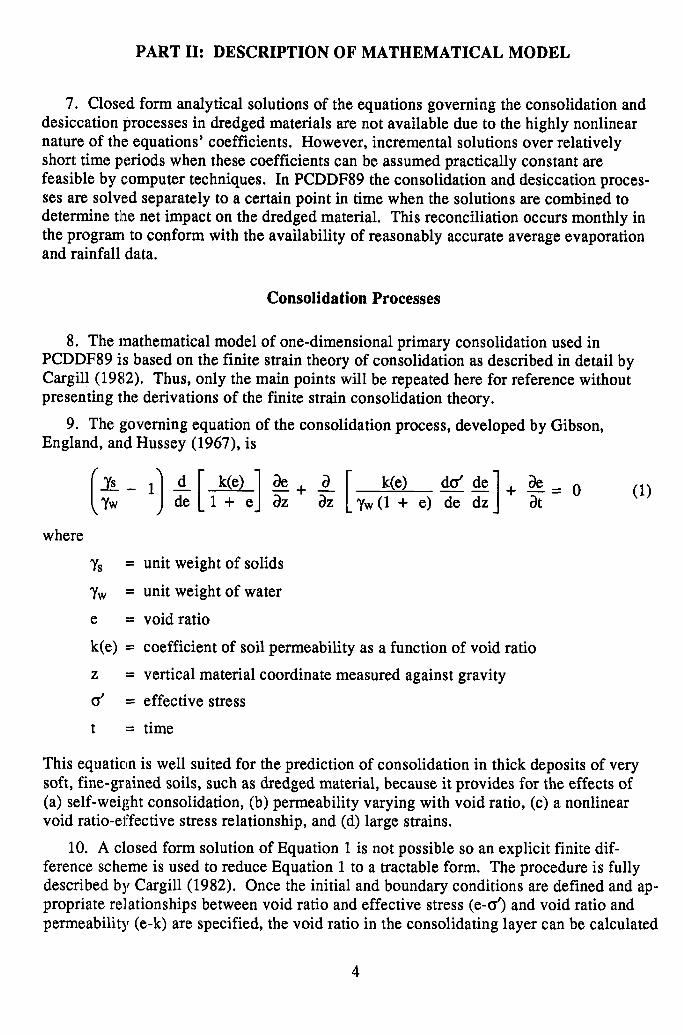
7. Closed form analytical solutions of the equations governing the consolidation and desiccation processes in dredged materials are not available due to the highly nonlinear nature of the equations’ coefficients. However, incremental solutions over relatively short time periods when these coefficients can be assumed practically constant are feasible by computer techniques. In PCDDF89 the consolidation and desiccation proces- ses are solved separately to a certain point in time when the solutions are combined to determine tlhe net impact on the dredged material. This reconciliation occurs monthly in the program to conform with the availability of reasonably accurate average evaporation and rainfall data.
Consolidation Processes
8. The mathematical model of one-dimensional primary consolidation used in PCDDF89 is based on the finite strain theory of consolidation as described in detail by Cargil! (19E12). Thus, only the main points will be repeated here for reference without presenting the derivations of the finite strain consolidation theory.
9. The governing equation of the consolidation process, developed by Gibson, England, and Hussey (1967), is
[$- 1) -g-$q z+ p [,,:“I ,,p)]+ $= 0 (1) where
YS = unit weight of solids
YW = unit weight of water
e = void ratio
k(e) = coefficient of soil permeability as a function of void ratio
Z = vertical material coordinate measured against gravity
0’ = effective stress
t = time
This equation is well suited for the prediction of consolidation in thick deposits of very soft, fine-grained soils, such as dredged material, because it provides for the effects of (a) self-weight consolidation, (b) permeability varying with void ratio, (c) a nonlinear void ratio-effective stress relationship, and (d) large strains.
10. A closed form solution of Equation 1 is not possible so an explicit finite dif- ference sche:me is used to reduce Equation 1 to a tractable form. The procedure is fully described by Cargill (1982). Once the initial and boundary conditions are defined and ap- propriate relationships between void ratio and effective stress (e-o’) and void ratio and permeability (e-k) are specified, the void ratio in the consolidating layer can be calculated
4
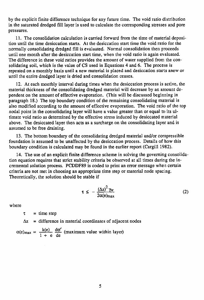
by the explicit finite difference technique for any future time. The void ratio distribution in the saturated dredged fill layer is used to calculate the corresponding stresse:s and pore pressures.
11. The consolidation calculation is carried forward from the time of material deposi- tion until the time desiccation starts. At the desiccation start time the void ratio for the normally consolidating dredged fill is evaluated. Normal consolidation then p:roceeds until one month after the desiccation start time, when the void ratio is again evaluated. The difference in these void ratios provides the amount of water supplied from. the con- solidating soil, which is the value of CS used in Equations 4 and 6. The process is repeated on a monthly basis until a new material is placed and desiccation starts anew or until the entire dredged layer is dried and consolidation ceases.
12. At each monthly interval during times when the desiccation process is active, the material thickness of the consolidating dredged material will decrease by an arnount de- pendent on the amount of effective evaporation. (This will be discussed beginning in paragraph 18.) The top boundary condition of the remaining consolidating material is also modified according to the amount of effective evaporation. The void ratio of the top nodal point in the consolidating layer will have a value greater than or equal to its ul- timate void ratio as determined by the effective stress induced by desiccated material above. The desiccated layer then acts as a surcharge on the consolidating layer and is assumed to be free draining.
13. The bottom boundary of the consolidating dredged material and/or compressible foundation is assumed to be unaffected by the desiccation process. Details of how this boundary condition is calculated may be found in the earlier report (Cargill 1982).
14. The use of an explicit finite difference scheme in solving the governing consolida- tion equation requires that strict stability criteria be observed at all times during the in- cremental solution process. PCDDF89 is coded to print an error message when certain criteria are not met in choosing an appropriate time step or material node spacing. Theoretically, the solution should be stable if
21- W2 YW We)max
(2)
where
z = time step
AZ = difference in material coordinates of adjacent nodes
Melmax = k(e) dd
1 + e de (maximum value within layer)
5

15. Another criterion that has been found to be useful in selecting a time step for input to the program is
2-C h
Woo) - N
where
h = layer thickness
coo = void ratio at zero effective stress
N = number of material nodes in a layer
16. An unstable calculation will usually be characterized by void ratios considerably outside the range of possible values or by zero consolidation when consolidation should be taking place. The cure for an unstable calculation is usually to decrease the time step chosen, but ,other input data should also be checked to ensure consistency.
17. Two options exist for selecting the relationship of the time step and grid size:
a. Biased on the compressibility and permeability characteristics entered as input d.ata, PCDDF89 will determine a simulation time increment and node spacing consistent with the stability criteria presented in Equations 2 and 3. For each problem, the initial dredged fill (and compressible foundation, if present) is represented by 10 equally spaced nodes, and a stable time-step is determined.
b. The user may determine values of the time step and grid size. An algorithm for choosing a stable time-step and grid size is presented in paragraph 59.
Desiccation Processes
18. The desiccation process is governed by many factors whose predictability is often difficult. Th.e empirical desiccation process described herein may seem inconsistent with the rather so,phisticated consolidation model. However, consolidation contributes the largest decrease in volume and thus should be analyzed using the most technically correct model. The development of a sophisticated theoretical model for desiccation is a subject for future research.
19. Desilccation of a dredged material is basically the removal of water by changing the state of tlhe water near the surface from a liquid to a gas. This change of state results primarily from evaporation and transpiration. Plant transpiration is considered insig- nificant due to the recurrent deposition of dredged fill and is therefore disregarded.
20. It ap;pears that the desiccation process occurs in two major stages. During the first stage, sufficient free water is available at the surface of the material so that evapora- tion takes place at its full potential rate. In the second stage of evaporation, drying proceeds at some fraction of the potential rate and this fraction decreases as the depth of dried crust increases.
6
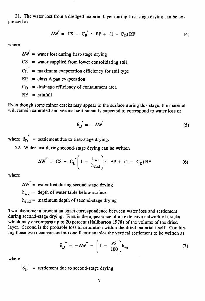
21. The water lost from a dredged material layer during first-stage drying (can be ex- pressed as
AW# = CS- C,‘* EP+ (l-C,,)RF (4)
where
AMJ’ = water lost during first-stage drying
cs = water supplied from lower consolidating soil
CE’ = maximum evaporation efficiency for soil type
EP = class A pan evaporation
CD = drainage efficiency of containment area
RF = rainfall
Even though some minor cracks may appear in the surface during this stage, the material will remain saturated and vertical settlement is expected to correspond to water loss or
SD’ = -AW? (5)
where SD' = settlement due to first-stage drying.
22. Water lost during second-stage drying can be written
A W” l EP+ (1- C,)RF (6)
where
A W” = water lost during second-stage drying
h wt = depth of water table below surface
h2nd = maximum depth of second-stage drying
Two phenomena prevent an exact correspondence between water loss and settlement during second-stage drying. First is the appearance of an extensive network of cracks which may encompass up to 20 percent (Haliburton 1978) of the volume of the dried layer. Second is the probable loss of saturation within the dried material itself. Combin- ing these two occurrences into one factor enables the vertical settlement to be written as
(7)
where
SD” = settlement due to second-stage drying
7
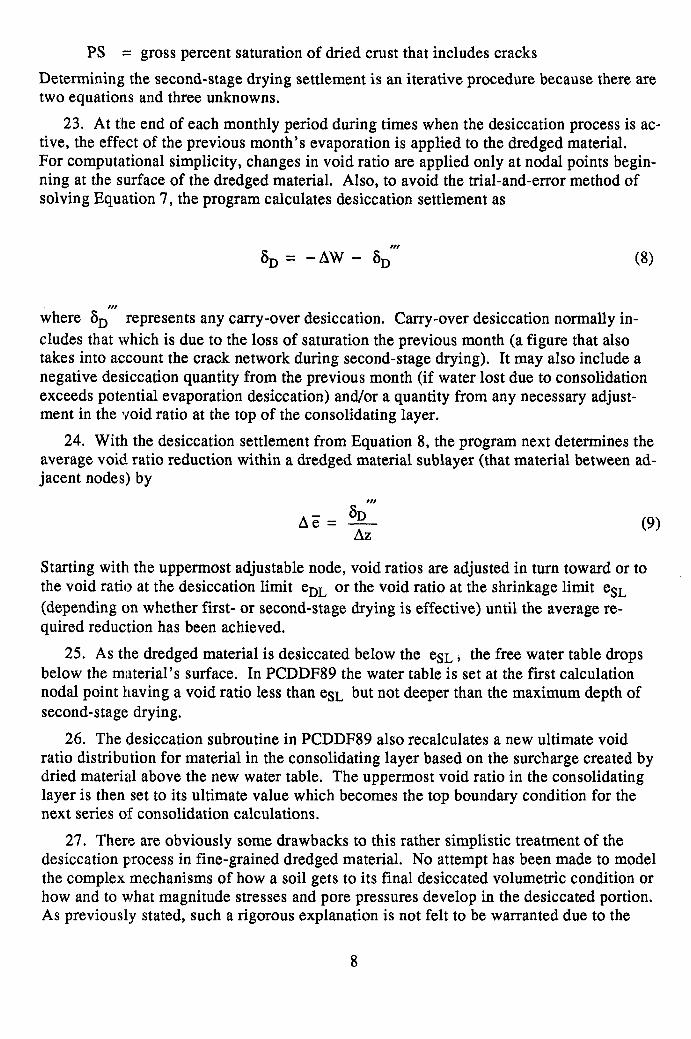
PS = gross percent saturation of dried crust that includes cracks
Determining the second-stage drying settlement is an iterative procedure because there are two equations and three unknowns.
23. At the end of each monthly period during times when the desiccation process is ac- tive, the effect of the previous month’s evaporation is applied to the dredged material. For computational simplicity, changes in void ratio are applied only at nodal points begin- ning at the surface of the dredged material. Also, to avoid the trial-and-error method of solving Equation 7, the program calculates desiccation settlement as
6, = - AW - SD”’ (8)
where S,“’ represents any carry-over desiccation. Carry-over desiccation normally in- cludes that which is due to the loss of saturation the previous month (a figure that also takes into ac:count the crack network during second-stage drying). It may also include a negative desiccation quantity from the previous month (if water lost due to consolidation exceeds potential evaporation desiccation) and/or a quantity from any necessary adjust- ment in the void ratio at the top of the consolidating layer.
24. With the desiccation settlement from Equation 8, the program next determines the average void ratio reduction within a dredged material sublayer (that material between ad- jacent nodes) by
(9)
Starting with the uppermost adjustable node, void ratios are adjusted in turn toward or to the void ratio at the desiccation limit eDL or the void ratio at the shrinkage limit eSL (depending on whether first- or second-stage drying is effective) until the average re- quired reduction has been achieved.
25. As the dredged material is desiccated below the eSL , the free water table drops below the material’s surface. In PCDDF89 the water table is set at the first calculation nodal point having a void ratio less than eSL but not deeper than the maximum depth of second-stage drying.
26. The desiccation subroutine in PCDDF89 also recalculates a new ultimate void ratio distribution for material in the consolidating layer based on the surcharge created by dried material above the new water table. The uppermost void ratio in the consolidating layer is then set to its ultimate value which becomes the top boundary condition for the next series of consolidation calculations.
27. There are obviously some drawbacks to this rather simplistic treatment of the desiccation process in fine-grained dredged material. No attempt has been made to model the complex mechanisms of how a soil gets to its final desiccated volumetric condition or how and to what magnitude stresses and pore pressures develop in the desiccated portion. As previousIy stated, such a rigorous explanation is not felt to be warranted due to the
8

overall effect is correctly represented, i.e., desiccation leads to a reduction of voids in the dried material. The presence of a dried surface does change the boundary condition in the consolidating material, and the effect of an extensively cracked crust is to increase the speed and magnitude of consolidation in the underlying material. The accuracy of this method obviously depends on properly defining the proposed quantities eSL and eDL and how well these quantities can be used to represent the true boundary condition of the con- solidating layer.
Deposition of Additional Dredged Materials
28. PCDDF89 allows the deposition of additional dredged material types at any time after filling begins. A total of 25 different types of dredged fill material can be used in a simulation. In the absence of any desiccation in prior deposits, there is a natural transi- tion between the old and new material since the void ratio at the top of the old is similar to that of the new. However, when the top of the old layer has been desiccated. and exten- sively cracked, there is no natural transition between the two layers. Again, the: program takes a simplistic approach in accordance with the mathematical model previously described.
29. When new material is deposited on top of the desiccrted fill, there is a discrepan- cy in the value of the actual void ratio at the boundary node. Due to probable extensive cracking at this point, it appears quite reasonable to approximate the actual void ratio as an average of the void ratio of the recently deposited material (the zero effective stress void ratio) and the desiccated void ratio. Void ratios in the remainder of previously desic- cated material are assumed to be maintained at their desiccated values.
30. While evidence exists to indicate that old dredged fill layer boundaries offer some enhancement to material drainage, it would be overly optimistic to assume these boun- daries are free draining for consolidation purposes. Therefore, future consolidation is based on an artificially set initial condition through the previously dried material. The ini- tial condition is shown in Figure 1; in the previously dried zone the conditions are based on a linear variation of void ratio between the boundary node at the zero effective stress void ratio and the node below the dried zone at a void ratio due to prior consolidation. This scheme of calculation is considered a realistic representation of the effect the pre- viously dried zone has on future consolidation.
Stresses and Pore Pressures
31. The total stress at any point in the layer is equal to the total weights of all materials in a unit area above that point. The effective stress at any point is determined using the void ratio and the measured void ratio-effective stress relationship. By the prin- ciple of effective stress, the total pore pressure uw(z,t) is the total stress minus the effec- tive stress. The excess pore pressure u(z,t) is
u(u) = q&t> - u&J)
where u0 is the static pore pressure.
(10)
9

32. In t.he consolidating material, effective stress is dependent on the input void ratio- effective stress relationship and exact values are interpolated between input points. At nodes where the void ratio has been desiccated below its ultimate value based on material weights, excess pore pressures are arbitrarily set to zero and effective stress is set equal to the effective weight of the material above.

PART III: PCDDF89 EXECUTION INFORMATION
33. PCDDF89 is coded in FORTRAN 77 and was compiled using Microsoft’s FORTRAN compiler version 4.1. PCDDF89 will execute on IBM (or compatible) microcomputers. A graphics card, at least 640K of random access memory, a math co- processor, and a hard disk are recommended. If a math co-processor is not installed, the user will encounter a “floating point error” message. The executable and example data files provided on the two distribution disks should be copied to an appropriate subdirec- tory (PCDDF89) on the hard disk using the DOS Copy command. Existing PCDDF data files may also be copied to this subdirectory,
INPCCDF Program
34. To start the interactive data input program, INPCDDF, the user changes to the PCDDF89 subdirectory (using the DOS “Change Directory” [CD] command), types INPCDDF, and presses “ENTER.” The interactive program will aid the creation of a new data file or the editing of an existing file. The interactive data input screens are described in Part IV. After the appropriate data file has been created, the user should exit to DOS, type PCDDF89, and press “ENTER” to execute PCDDF89. PCDDF89 will prompt the user for the input data file name, the output data file name, and an indication of whether the user desires a plot of the surface elevations as a function of time. If a plot of the sur- face elevation over time is desired, PCDDF89 will require the name of a plot file. The number of data points on the surface elevation plot will be equal to the number of print times specified in the input data file. If the input data set specifies a continuation file to be created, the program will also require the name of a continuation file. A continuation file stores the output from a previous simulation so the simulation can be restarted at a later time.
35. After entering the required file names, PCDDF89 will begin solving the consolida- tion/desiccation problem. The output will be displayed on the screen and recorded in the output file as the calculations progress. Execution of the program will be complete when the cumulative mass error is displayed. If execution of the program is terminated before completion of a particular simulation, the output up to that point will be written to the out- put file.
GRAPH Program
36. If a plot of the surface elevation as a function of time is desired, the user executes the program GRAPH, which is included on the PCDDF89 distribution disk. This program is started by typing GRAPH and pressing “ENTER.” The program will ask the user a series of questions about the computer equipment and how the user wishes to have the graph set up. In order to display the graph on the screen, the user must have a graphics card installed. In order to get a hard copy of the graph, the user must have an IBM Graphics or compatible printer. The plot file, which is created in the ASCII format, can also be plotted with a spreadsheet program or another graphics package. The first line of
11

the file is thle number of data sets in the file, the second line is the number of data points in the data set, and the remainder of the lines contain surface elevation and time data.
Suggestions for Executing PCDDF89
37. This section contains some useful suggestions for executing PCDDF89. If a long- term simulation is planned, a short-term simulation should be conducted first to verify the input data and check for obvious errors in the data set.
38. Thin layers of the same material type may be combined without the loss of ac- curacy if the total simulation is two to five times the period of the lumped thin layers, For example, a 20-year disposal sequence with annual deposits of 1.0 ft (0.3048 m) can be accurately simulated by combining the first 4 years of the deposits into an initial lift of 4.0 ft (1.22 m). This suggestion is feasible since the time of interest (20 years) is sig- nificantly longer than the period over which the dredged material deposits are combined. This approach also has advantages since the time step and grid size (see paragraph 59) are determined from the initial layer characteristics.
39. PCDDF89 is designed to accept any consistent set of engineering units. However, consistency within a particular system must be maintained. For example, if the English unit system is used, the following units must be used for these variables: time in days, length in feet, force in pounds, permeability in feet/day, effective stress in pounds/square foot, and monthly rainfall and evaporation in feet.
12

PART IV: PCDDFS9 INTERACTIVE DATA INPUT PROGRAM
Interactive Data Input Program
40. A comprehensive interactive data input program was developed to facilitate the use of PCDDF89. The interactive program, INPCDDF, is coded in Basic and compiled using Borland’s TurboBasic version 1.1. A summary and explanation of the error mes- sages for INPCDDF are given in Appendix A.
41. The interactive program utilizes the screen method of input where values are entered on the screen in the locations or boxes provided. This input technique is very similar to the use of a spreadsheet program. INPCDDF can create new or edit existing PCDDF89 data files and can easily convert existing PCDDF data files to the new PCDDF89 format. INPCDDF also allows the creation of new or the editing of existing restart data files. The restart option allows a previous simulation to be restarted or con- tinued. The output from the last time increment analyzed in the previous simulation is stored in a continuation file and is used in the restart. The restart data file specifies the new time increments, dredged fill heights, and soil properties to be analyzed.
Operation of Interactive Input Data Screens
42. Data is inputted directly from the keyboard and stored in the computer’s random access memory. If the file is not saved using one of the options in the main INPCDDF menu, the new data will be lost when the program is terminated. The main menu and data input screens are shown in Appendix B and are described in the following paralgraphs.
43. To edit existing data, the user must use the backspace key to delete the current entry before typing in the new data. The backspace key is used instead of just overtyping to reduce the chance of accidentally entering an incorrect character into the data set. The user can move to the next data field using the cursor keys or by pressing “ENTER.” To move to the next input screen the user must press one of the function “F” keys depending on the desired destination. The “F” keys were selected in lieu of the “ENTER’” key be- cause users have a tendency to press “ENTER” after inputting data.
INPCDDF Input Options
44. In the first INPCDDF menu, Figure Bl, the user has four main options: (a) to cre- ate a new PCDDF89 data file, (b) to edit an existing PCDDF89 data file, (c) to convert an old PCDDF data file to the new PCDDF89 format, or (d) to create or edit a data file for restarting a previous simulation. The user should press the letter representing the desired INPCDDF input option.
45. Creating a new PCDDF89 data file. After pressing “N” at the initial INPCDDF menu, the user will be prompted for the name of the new PCDDF89 data file, Figure B2. The user should enter the full file name, including the drive and/or subdirectory, of the new data file. After entering the file name, the user presses Fl to move to the main INPCDDF menu, Figure B3. The user should type “1” (“CREATE A NEW DATA FILE
13

OR EDIT CURRENT DATA FILE”) and press “ENTER” to create a new data file. The in- teractive program will prompt the user for all the data’required in data groups 2 through 10 shown in the main INPCDDF menu. Paragraphs 50 through 66 describe the data re- quired. At alny time during the input process the user can return to the main menu by pressing F2. At the main menu the user can go back and edit a previous data group, save the file, and/or exit the program.
46. The user should finish entering all data in a particular group before returning to the main INPCDDF menu. This will facilitate locating the point where data input was ter- minated. When data input is continued, the user may select the number that corresponds to the next group of data that must be entered.
47. Editing an existing PCDDF89 data file. After pressing “E” at the initial INPCDDF menu, Figure Bl, the user will be prompted for the name of the existing PCDDF89 data file, Figure B4. After typing in the full file name, including the drive and/or subdirectory where the file is located, the user presses Fl to move to the next input screen, Figure B5. The user is prompted for the name of the new PCDDF89 data file after editing. If the user enters the same name as the existing data file, the original data file will be overwritten when the file is saved. After entering the new file name, the user presses Fl to move to the main INPCDDF menu. At the main menu, the user should select the number of the data group that requires editing. Paragraphs 50 through 66 describe the input required in each data group.
48. Converting an existing PCDDF data file to the new PCDDF89 format. After pressing “C” at the initial INPCDDF menu, Figure Bl, the user will be prompted for the name of the #existing PCDDF data file, Figure B4. After typing in the full file name, in- cluding the drive and/or subdirectory where the file is located, the user will be prompted for the name of the new PCDDF89 data file, Figure B5. If the user enters the same name as the existing PCDDF data file, the original file will be overwritten when the file is saved. After entering the new file name, the user presses Fl to move to the main INPCDDF menu, Figure B3. The user should select the appropriate option, 11 or 12, to save the data. file. After saving, the old data file has been successfully converted and can now be used to execute PCDDF89. The data file will be analyzed 20 percent faster using PCDDF89 thian the previous version of PCDDF as a result of the recent modifications.
49. Creating or editing a restart data file. After pressing “R” at the initial INPCDDF menu, Figure B 1, the user will choose whether to create a new restart data file or edit an existing restart data file. The restart option allows the user to restart or con- tinue a previlous consolidation/desiccation simulation. The entire restart option is described in Part V of this user’s guide.
Main PCDDFS9 Data Input Groups
50. INPCDDF prompts the user for the data required in the nine major groups of input required by PCDDF89. The nine groups are shown in the main INPCDDF menu, Figure B3, and are numbered 2 through 10. Data group 1 is used to create a new PCDDF89 data file. The next nine sections describe the input required in the nine data groups listed below:
a. Program execution data.
14

b, Compressible foundation material properties.
c. Material properties of first dredged fill layer.
d. Incompressible foundation material properties.
e. Execution time increment and grid size.
f. Print times and new dredged fill material properties.
g. Desiccation properties of dredged fill.
h. Evaporation and precipitation data.
i. Final dredged fill desiccation parameters.
Program execution data
5 1. This data input group has two data input screens that can be accessed directly by typing 2 and pressing “ENTER” at the main INPCDDF menu. The data required consist of program execution parameters that are used to determine whether the data file is for a new simulation or a restart of a previous simulation. The data also include a 4#0-character problem description that may include any character except single quotes, i.e., ‘. An op- tion to save the output in a continuation file that can be used for restart purpos~es is also in- cluded. The input required is described in Table 1 and copies of the two data input screens are shown in Figure B6.
Compressible foundation material properties
52. If the foundation is determined to be compressible, the material properties re- quired to calculate the resulting settlement must be entered. The compressible foundation option has five data input screens for the first material type. Each additional foundation material type requires data for the last four screens in this group. The input relquired is described in Table 2; copies of the data input screens are shown in Figures B7 and B8.
53. Normally the laboratory consolidation test results are plotted and a smoothed curve is drawn through the data. Values of effective stress and permeability are then determined for every 0.25 change in void ratio to produce a data set of 30 to 40 points from the smoothed curve. This data interpretation technique results in fewer interpolation errors in PCDDF89.
54. The interactive data input program will repeat screens 2 through 5 for (each dif- ferent material type in the compressible foundation, i.e., NUMBL times. If an:y dredged fill or compressible foundation layer has the same material properties as a previously entered layer, the same material identification number should be entered in screen 2 and the user will only be prompted for the initial thickness of the layer in screen 3. The material properties for screens 4 and 5 will be automatically loaded using the data entered previously for the same material identification number.
55. If the layer has a new material identification number, the user will be prompted for the data in screens 4, 4A, and 5, which are shown in Figure B8. Data input screen 4A prompts the user for the source of the material properties. The void ratio-e,ffective stress and void ratio-permeability relationships required in screen 5 can be inputted inter- actively, option 0, or loaded from an existing data file using options 1 or 2. If option 1 or 2 is selected, the user will be prompted for the full file name of the existing data file
15

containing the material properties using the input screen in Figure B9. If option 1 is selected, input screen 5 will be omitted. If option 2 is selected, the data loaded from the existing file will be displayed in screen 5 and the user may edit the data.
Material properties for first dredged fill layer
56. Two data input screens are required to enter the material properties of the first dredged fill layer. The input required is described in Table 3 and copies of the input screens are sihown in Figure BlO. Additional layers of dredged fill materials can be added in data input group F. Input screen lA, Figure BlO, will appear before input screen 2 and prompts the user for the source of the material properties for the first dredged fill layer (see paragraph 55 for details).
Incompressiible foundation material properties
57. The incompressible foundation material requires one data input screen. Table 4 describes the necessary input parameters which must be entered for all simulations, whether or not the site has a compressible foundation. A copy of the input screen for this data group is shown in Figure B 11.
Execution tiime increment and grid size
58. The execution time increment and grid size used in the execution of PCDDF89 can be determined by the user or by the program. Copies of the input screens are shown in Figure B12; the necessary input parameters are described in Table 5. Only two data input screens are required whether the user or the program determines the time increment and grid size..
59. The following criteria are presented to facilitate the determination of a stable set of values for the time increment and grid size. In particular, guidelines for determining NBDIVl and TAU are presented.
a. DIetermine maximum value of a(e) using the compressibility data where
K(e) do’ a(e) = - - 1 + e de
b. Select the number of sublayers that the initial dredged fill layer will be divided into for computational purposes, NBDIV. A minimum of three layers is re- quired to simulate the desiccation process. (see paragraphs 60 through 62 for guidelines.)
c. Calculate the height of solids within one grid height from the relationship
HDF
t 1 1 + coo
AZ = NBDIV
where
HDF = initial dredged fill thickness
16
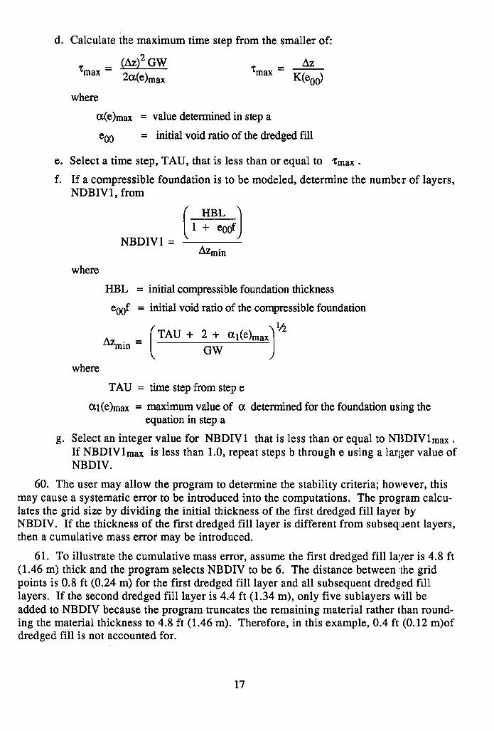
d. Calculate the maximum time step from the smaller of:
zmax = * max
AZ z - max = K(eOd
where
a(e) = value determined in step a
coo = initial void ratio of the dredged fill
e. Select a time step, TAU, that is less than or equal to Zmax .
f. If a compressible foundation is to be modeled, determine the number of layers, NDBIV 1, from
HBL
l 1 1 + eoof NBDIVl =
Azrnin
where
HBL = initial compressible foundation thickness
e0of = initial void ratio of the compressible foundation
l/i Azmin =
TAU + 2 + al(e) GW
where
TAU = time stepfromstep e
al(e) = maximum value of a determined for the foundation us:ing the equation in step a
g. Select an integer value for NBDIVl that is less than or equal to NBDIVlmax . If NBDIVlmax is less than 1.0, repeat steps b through e using a larger value of NBDIV.
60. The user may allow the program to determine the stability criteria; however, this may cause a systematic error to be introduced into the computations. The program calcu- lates the grid size by dividing the initial thickness of the first dredged fill layer by NBDIV. If the thickness of the first dredged fill layer is different from subsequent layers, then a cumulative mass error may be introduced.
61. To illustrate the cumulative mass error, assume the first dredged fill layer is 4.8 ft (1.46 m) thick and the program selects NBDIV to be 6. The distance between ,the grid points is 0.8 ft (0.24 m) for the first dredged fill layer and all subsequent dredged fill layers. If the second dredged fill layer is 4.4 ft (1.34 m), only five sublayers will be added to NBDIV because the program truncates the remaining material rather than round- ing the material thickness to 4.8 ft (1.46 m). Therefore, in this example, 0.4 ft (0.12 m)of dredged fill is not accounted for.
17

62. PCDDF89 does monitor the amount of dredged fill that is not accounted for and at the termination of each simulation reports the cumulative mass error. The error is calcu- lated by dividing the amount of dredged fill not accounted for by the total dredged fill added and isi expressed as a percent. Generally the program’s value of NBDIV is suffi- ciently small so that the error is negligible. The mass error can be avoided by choosing a grid size that fits all of the anticipated layer thicknesses and/or rounding the layer thick- nesses to fit the grid size. If the cumulative mass error is greater than 10 percent, the user should modify the input to reduce the value of cumulative mass error.
Print times and new dredged fill layer material properties
63. This data group specifies the times for which output data will be printed. (Time is measured in days from the time of deposition of the initial dredged material layer.) Input parameters for this group are described in Table 6. Dredged fill layers can be added at any time during the simulation using this option. The new dredged fill layer may have the same or different material properties as previously added layers. If the material properties are the same as a previous layer, only data input screens 1 through 3 will be required. If the material properties are different than previous dredged fill layers, data input screens 1 through 5 will be required. Each set of data screens will be repeated for each print time for a total of NTIME times. Copies of the input screens are shown in Figures B13 and B14. Input screen 4A, Figure B14, will appear before input screen 5 and prompts the user for the source of the material properties for the new dredged fill layer. (See paragraph 55 for details.)
Desiccation properties of dredged fill
64. The desiccation parameters of the dredged fill material are inputted using the single data s’creen in this group. Input parameters for this group are described in Table 7. The average desiccation parameters for all the dredged fill materials should be used in this data group. Due to the uncertainties involved in the empirical desiccation model and in the interaction of previously dried material with new dredged fill layers, the program was not modified to incorporate desiccation parameters for each material type. The development: of a sophisticated desiccation model is a subject for future research. How- ever, the use of average desiccation parameters and the empirical model has been found to provide a good estimate of the settlement due to desiccation. A copy of the data input screen for this group is shown in Figure B15.
Evaporation and precipitation data
65. Average evaporation and rainfall data for the containment area are entered in this data group. Copies of the three data input screens used in this group are shown in Figure B16; the input data are described in Table 8. The required precipitation and evaporation data can be inputted interactively or loaded from an existing data file. As a result, input screen 1 in Figure B16 appears first to determine the source of the data. Option 0 will allow the user to input the data directly into screen 2. Options 1 and 2 will allow the user to load the data from an existing file and omit screen 2 (option 1) or edit the data in screen 2 (option 2). If option 1 or 2 is selected, the user will be prompted for the full file name of the existing data file (including drive and/or subdirectory) containing the evapora- tion and precipitation data, using input screen 1A in Figure B16.
18

I Final dredged fill desiccation parameters / 66. This data group requires the parameters that describe the desiccation and sub-
sequent cracking of the dredged fill. The average values of these parameters for all the dredged fill layers should be used. A copy of the data input screen used in this group is
/ shown in Figure B17. The input data are described in Table 9.
i Data file option for PCDDF89 input
67. The data required to execute PCDDF89 are described in the data input screens and can be entered interactively using INPCDDF. However, users can also create data files using an editor or word processor that has a nondocument mode available to generate an ASCII data file, i.e. a file without embedded control characters. For an initial (execution of a consolidation and desiccation simulation, the data file should be sequenced as shown in Table 10. The variables have been described previously in Tables 1 through1 9, except for NST, which is an integer line number for each line of input data. The data on each line must be separated by a blank space. Real data may be written in either exponential or decimal format, but integer data must be written without a decimal. The variables high- lighted in bold type illustrate the additional information required by PCDDF89 to analyze different types of dredged fill and compressible foundation materials.
/ 19

PART V: PCDDF89 RESTART OPTION
Introduction
68. PCDDF89 is designed such that the results from a previous consolidation/desicca- tion simulat:ion can be stored in a continuation file. This continuation file can be used to restart or continue the simulation at some future time. To restart a simulation, the con- tinuation file from the previous execution and a restart data file are needed. The restart data file contains information on the number of time periods, the dredged fill layers, and the print opt.ions that will be used when the simulation is restarted. Three major groups of data are required to restart a continuation file, and they are described in paragraphs 74 through 77.
INPCDDF Restart Options
69. In the first INPCDDF menu, Figure Bl, the user can create or edit a data file for restarting a :previous simulation. After pressing “R” at the initial INPCDDF menu, the user will choose whether to create a new restart data file or edit an existing data file using the input screen shown in Figure B18.
70. Creiating a new PCDDF89 restart data file. After pressing “N” at the initial IN- PCDDF restart menu, the user will be prompted for the name of the new restart data file, Figure B19. The user should enter the full file name, including the drive and/or subdirec- tory, of the new data file. After entering the file name, the user presses Fl to move to the next input screen, which requires the name of the previously saved continuation file, Figure B20. After entering the full file name, the user presses Fl to move the user to the main INPCDDF restart menu, Figure B21. The user should type “1” (“CREATE NEW RESTART DATA FILE OR EDIT CURRENT DATA FILE”) and press “ENTER” to cre- ate a new data file. INPCDDF will prompt the user for all the data required in data groups 2 through 4 shown in the main INPCDDF restart menu. Paragraphs 74 through 77 describe the data required. At any time during the input process the user can return to the main menu by pressing F2. At the main menu the user can go back and edit a previous data group, isave the file, and/or exit the program.
71. The user should finish entering all data in a particular group before returning to the main INPCDDF menu. This will facilitate locating the point where data input was ter- minated. When data input is continued, the user may select the number which cor- responds to the next group of data that must be entered.
72. Editing an existing PCDDF89 restart data file. After pressing “E” at the initial INPCDDF restart menu, Figure B18, the user will be prompted for the name of the exist- ing restart data file, Figure B22. After typing in the full file name, including the drive and/or subdirectory where the file is located, the user presses Fl to move to the next input screen, Figure B23. This screen prompts the user for the full file name of the previously saved continuation file. After entering the full file name, the user presses Fl to move to the next input screen, Figure B24. This screen prompts for the name of the new PCDDF89 restart data file after editing. If the user enters the same name as the existing data file, the original data file will be overwritten when the file is saved. After entering
20

the new file name, the user presses Fl to move to the main INPCDDF restart menu, Fig- ure B21. At the main menu, the user should select the number of the data group that re- quires editing. Paragraphs 74 through 77 describe the input required in each data group.
Main PCDDF89 restart data input groups
73. INPCDDF prompts the user for the data required in the three major groups of input required by the restart option in PCDDF89. The three groups are shown in the main INPCDDF restart menu, Figure B21, and are numbered 2 through 4, Data group 1 is used to create a new PCDDF89 restart data file. The next three sections describe the input re- quired in these three groups, which are listed below:
a. Program execution data.
b. Print times and dredged fill data from last simulation.
c. Print times and new dredged fill layer data.
Restart program execution data
74. This restart group has two data input screens which are shown in Figure B25. The data required consist of program execution parameters which are used to determine if a new continuation file will be created and the number of print times used during the re- start. This data also includes a 40-character problem description that may include any character except single quotes, i.e., ‘. The input required is described in Table 11.
Restart dredged fill data from previous simulation
75. This restart group requires data for the last dredged fill layer placed in the pre- vious simulation. One data input screen is required and the information is obtained from the data file for the previous simulation. A copy of this data input screen is shown in Fig- ure B26. The required data are described in Table 12. The data for this restart group must be identical to those entered in the main data group for print times and new dredged fill layer material properties (data fields 2 through 5, see Table 6). Data must be identical to those entered for the last print time analyzed in the previous simulation.
Restart print times and new dredged fill layer data
76. This data group specifies the times for which data will be printed. (Time is measured in days from the time of deposition of the initial dredged material layer.) Dredged fill layers can be added at any time during the restart of a previous simulation using this option. The new dredged fill layer may have the same or different material properties as previously added layers. If the material properties are the same as a pre- vious layer, only data input screens 1 through 3 will be required. If the material proper- ties are different than previous dredged fill layers, data input screens 1 through 5 will be required. Each set of data screens will be repeated for each print time, i.e., NTIME times. Copies of the input screens are shown in Figures B27 and B28; the required da.ta are described in Table 13.
77. If the layer has a new material identification number, the user will be prompted for the data in screens 4, 4A, and 5, which are shown in Figure B28. Data input screen 4A prompts for the source of the material properties. The void ratio-effective stress and void ratio-permeability relationships required in screen 5 can be inputted interactively,
21

option 0, or loaded from an existing data file using options 1 or 2. If option 1 or 2 is selected, the user will be prompted for the full file name of the existing data file contain- ing the material properties using the input screen in Figure B29. If option 1 is selected, input screen 5 will be omitted. If option 2 is selected, the data loaded from the existing file will be displayed in screen 5 and the user may edit the data.
Data File Option for PCDDF89 Restart Input
78. The data input required to restart a previous PCDDF89 simulation is described in the data input screens and can be entered interactively using INPCDDF. However, users can also cremate data files using an editor or word processor that has a nondocument mode available to generate an ASCII data file, i.e., a file without embedded characters. For the restart of a previous consolidation/desiccation simulation, the data file should be se- quenced as shown in Table 14. The variables have been described previously in Tables 11 through 113 except NST, which is an integer line number for each line of input data. The data on each line must be separated by a blank space. Real data may be written in either exponential or decimal format, but integer data must be written without a decimal. The variable:s highlighted in bold type illustrate the additional information required by PCDDF89 to analyze different types of dredged fill and compressible foundation materials.
22

PART VI: PCDDF89 OUTPUT
Description and Explanation of PCDDF89 Output
79. The output from PCDDF89 is written to an ASCII data file that is named by the user. In addition, a partial listing of the output is displayed on the monitor as the program is executing, including the current time of the simulation, the settlement, and the surface elevation. The output data file from the program starts by echoing the execution input data file. Then, PCDDF89 interprets the data file and writes the input data in organized tables. After writing the input data, the program writes the initial conditions of the dredged fill at the nodal points in the initial lift thickness. The output describing the con- ditions of the compressible foundation and dredged fill materials is printed at the specified print times using the same tabular format as the input data. The restart option only writes the output describing the conditions of the compressible foundation and dredged fill at the specified print times and does not repeat the initial conditions. If English engineering units are used consistently throughout the simulation, the output parameters and their units are listed in Table 15. Sample PCDDF89 outputs are shown in paragraphs 81 and 82, which contain two example simulations.
80. The following two examples are presented to illustrate the use of PCDIDF89. The data files for the examples described in this section are included on the PCDDF89 distribu- tion disks.
Example 1: Compressible Foundation and Multiple Dredged Fill Layers
8 1. This example describes the input for two different layers of dredged fill placed on a compressible foundation. The first dredged fill layer is placed at time equal zero days and has an initial lift thickness of 10 ft (3.048 m). The second dredged fill material type is applied at 300 days with an initial height of 1.2 ft (0.37 m). The settlement ‘of the foun- dation and dredged fill is calculated at 90, 180, 300, and 450 days. Figure 2 shows the sample input and Figure 3 shows the resulting output. The results were also saved in a continuation file named EXlCONT.OUT, which will be used in Example 2.
Example 2: Restart of Example 1
82. This example illustrates how the results of a previous simulation can be used to restart or continue the sim.ulation. The results of the previous simulation are read to PCDDF89 from a continuation file. A restart data file contains information on the num- ber of time periods, the dredged fill layers, and the print options that will be used when the simulation is restarted. Restart data are shown in Figure 4, which continues the simulation to 600 and 700 days. As shown, no additional dredged fill is added during the restart in this example. Output from the restart is shown in Figure 5.
23
REFERENCES
Cargill, K.W. 1982. “Consolidation of Soft Layers by Finite Strain Analysis,” Miscel- laneous Paper GL-82-3, US Army Engineer Waterways Experiment Station, Vicksburg, MS.
Cargill, K.W. 1985. “Mathematical Model of the Consolidation/Desiccation Processes in Dredged Material,” Technical Report D-85-4, US Army Engineer Waterways Experi- ment Station, Vicksburg, MS.
Gibson, R.E., England, G.L., and Hussey, M.J.L. 1967. “The Theory of One-Dimen- sional Consolidation of Saturated Clays; Vol I. Finite Non-Linear Consolidation of Thin Homogeneous Layers,” Geotechnique, Vol 17, No. 3, pp 261-273.
Goforth, G.F. 1985. Addendum to “Mathematical Model of the Consolidation/Desicca- tion Processes in Dredged Material,” Technical Report D-85-4, US Army Engineer Water- ways Experiment Station, Vicksburg, MS.
Haliburton, T.A. 1978. “Guidelines for Dewatering/Densifying Confined Dredged Material,” Tlechnical Report DS-78- 11, US Army Engineer Waterways Experiment Sta- tion, Vicksburg, MS.
Poindexter, 1M.E. 1988. “Behavior of Subaqueous Sediment Mounds: Effect on Dredged Material Disposal Site Capacity,” Ph.D. dissertation, Texas A&M University, College Station, TX.
Schroeder, P.R. 1988. “Automated Dredging and Disposal Alternatives Management System, Users Guide,” Draft Instructional Report, US Army Engineer Waterways Experi- ment Station, Vicksburg, MS.
US Army Corps of Engineers. 1987. “Confined Disposal of Dredged Material,” En- gineer Manual EM 1110-2-5027, Washington, DC.
24

Table 1 Program Execution Data
Input Data Screen Field Variable Descriution
1 NDATAl Integer denoting the following options: 1 = new simulation. 2 = restart or continuation of a previous simulation.
2 NDATA2 Integer denoting the following options: 1 = output not saved in a continuation file. 2 = output saved in a continuation file for subsequent restart of
simulation.
3 NPROB Description of simulation which can be a maximum of any 40 characters except a single quote, i.e., ‘.
1 Integer denoting the following options: 1 = complete program execution, printing soil data, initial conditions,
and current conditions for all specified print times. 2 = complete program execution but do not print soil data and initial
conditions. 3 = terminate program execution after printing soil data and initial
conditions.
2 2 NBL Integer denoting the following options: 1 = foundation is compressible and consolidation is calculated for
foundation and dredged fill. 2 = foundation is incompressible and consolidation is calculated for
only dredged fill.
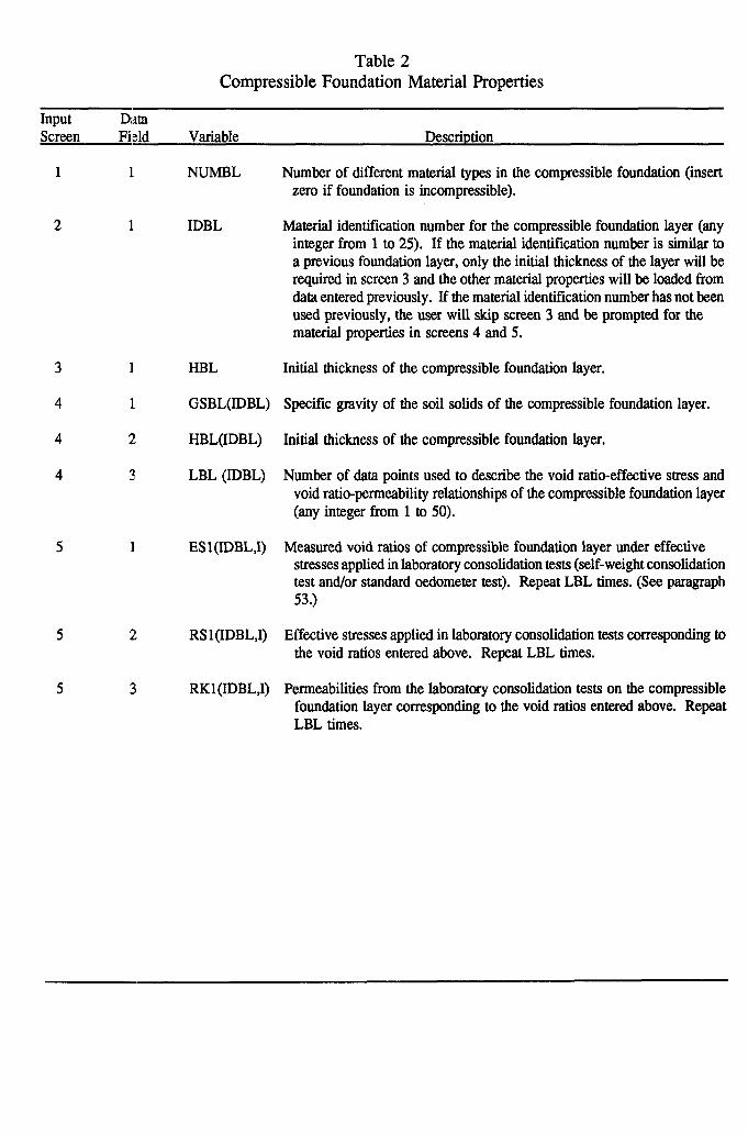
Table 2 Compressible Foundation Material Properties
Input Screen
Data Fkld Variable Descriution
1 I
2 1 IDBL
3 I
4 I
4 Y#
4 3
5 I
2:
?i
NUMBL
HBL
GSBL(IDBL)
HBL(IDBL)
LBL (IDBL)
ESl(IDBL,I)
RS l(IDBL,I)
RKl(IDBL,I)
Number of different material types in the compressible foundation (insert zero if foundation is incompressible).
Material identification number for the compressible foundation layer (any integer from 1 to 25). If the material identification number is similar to a previous foundation layer, only the initial thickness of the layer will be required in screen 3 and the other material properties will be loaded from data entered previously. If the material identification number has not been used previously, the user will ship screen 3 and be prompted for the material properties in screens 4 and 5.
Initial thickness of the compressible foundation layer.
Specific gravity of the soil solids of the compressible foundation layer.
Initial thickness of the compressible foundation layer.
Number of data points used to describe the void ratio-effective stress and void ratio-permeability relationships of the compressible foundation layer (any integer from 1 to 50).
Measured void ratios of compressible foundation layer under effective stresses applied in laboratory consolidation tests (self-weight consolidation test and/or standard oedometer test). Repeat LBL times. (See paragraph 53.)
Effective stresses applied in laboratory consolidation tests corresponding to the void ratios entered above. Repeat LBL times.
Permeabilities from the laboratory consolidation tests on the compressible foundation layer corresponding to the void ratios entered above. Repeat LBL times.
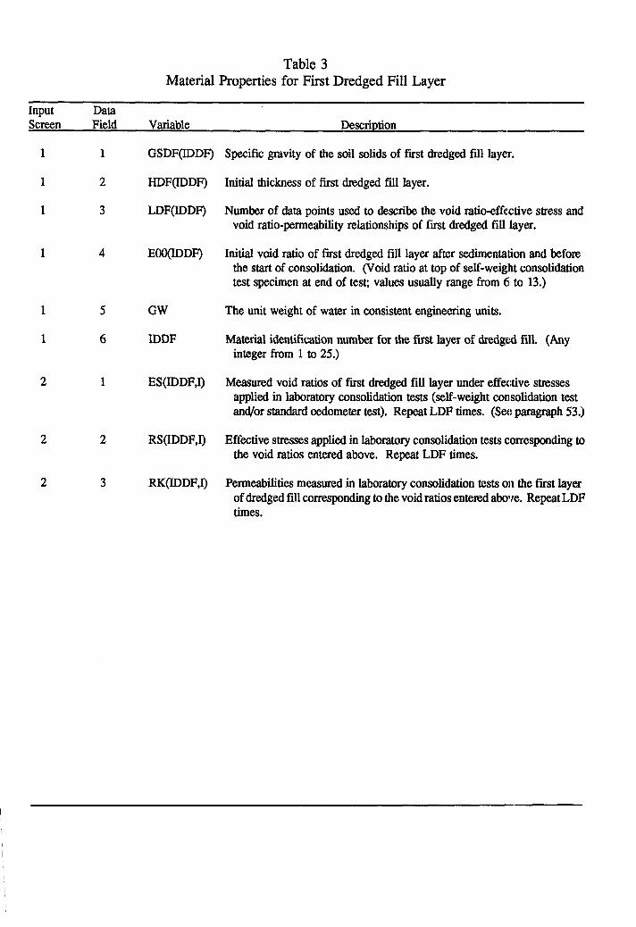
Table 3 Material Properties for First Dredged Fill Layer
Input Data Screen Field
1 1
1 2
1 3
Variable
GSDF(IDDF)
HDF(IDDF)
LDF(IDDF)
1 4 EWDDF)
1 5 GW
1 6 IDDF
2 1 ES(IDDF,I)
2 2
2 3
RS(IDDF,I)
RK(IDDF,I)
Descriution
Specific gravity of the soil solids of first dredged fill layer.
Initial thickness of first dredged fill layer.
Number of data points used to describe the void ratio-effective stress and void ratio-permeability relationships of first dredged fill layer.
Initial void ratio of first dredged fill layer after sedimentation and before the start of consolidation. (Void ratio at top of self-weight consolidation test specimen at end of test; values usually range from 6 to 13.)
The unit weight of water in consistent engineering units.
Material identification number for the first layer of dredged fill. (Any integer from 1 to 25.)
Measured void ratios of fist dredged fill layer under effective stmsses applied in laboratory consolidation tests (self-weight consolidation test and/or standard oedometer test). Repeat LDF times. (See paragraph 53.)
Effective stresses applied in laboratory consolidation tests corresponding to the void ratios entered above. Repeat LDF times.
Permeabilities measured in laboratory consolidation tests on the first layer of dredged fill corresponding to the void ratios entered above. Repeat LDF times.
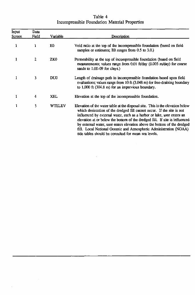
Table 4 Incompressible Foundation Material Properties
Input Data Screen Field Variable Description
1 1 EO Void ratio at the top of the incompressible foundation (based on field samples or estimates; EO ranges from 0.5 to 3.0.)
1 2 ZKO Permeability at the top of incompressible foundation (based on field measurements; values range from 0.01 ft/day (0.003 m/day) for coarse sands to l.OE-09 for clays.)
1 3 DUO Length of drainage path in incompressible foundation based upon field evaluations; values range from 10 ft (3.048 m) for free-draining boundary to 1,000 ft (304.8 m) for an impervious boundary.
1 XEL Elevation at the top of the incompressible foundation.
1 5 WTFLEV Elevation of the water table at the disposal site. This is the elevation below which desiccation of the dredged fill cannot occur. If the site is not influenced by external water, such as a harbor or lake, user enters an elevation at or below the bottom of the dredged fill. If site is influenced by external water, user enters elevation above the bottom of the dredged fill. Local National Oceanic and Atmospheric Administration (NOAA) tide tables should be consulted for mean sea levels.

Table 5 Time Increment and Grid Size
Input Screen
Data Field Variable Description
1 1 IMPLY
2 1 NTIME
3 1 NBDIV
3 2 NBDIVl Number of parts the compressible foundation layer is divi.ded into for computational purposes. (See paragraph 59 for guidelines on determining NBDIVl.)
3 3 TAU Value of the time step used in the finite difference calculations. (See subsequent paragraph 59 for guidelines on determining TAU.)
3 4 NTIME Number of output or print times during simulation.
Integer denoting the following options: 1 = PCDDF89 will determine the time increment and grid size to satisfy
stability criteria for the number of print times specified in NTIME (input screen 2).
2 = user will input time increment and grid sizes in input screen 3.
Number of output or print times during the simulation. (This screen will appear if IMPLY = 1. The following screen will appear if IMPLY = 2.)
Number of parts the first layer of dredged fill is divided into for computational purposes. A minimum of three layers is required to simulate the desiccation process. (See paragraphs 60 through 62 for guidelines on determining NBDIV.)

Table 6 Print Times and New Dredged Fill Layer Data
Input Data Screen Field Variable Description
1 1 pm0
2
3
4
4
4
5
1 IDDF
1
1 ES(IDDF,I)
2
3
AHDF(l)
ATDS(I)
mso
NNsc(I)
EOO(IDDF)
GSDF(IDDF)
LDF(IDDF)
EOO(IDDF)
RS(IDDF,I)
RKWDF,I)
Times at which the properties of the consolidating layers will be printed and/or a new layer of dredged fill will be applied. PRINT(I) should be expressed in cumulative number of time periods (usually days) from the addition of the first layer of dredged fill. This screen will be repeated NTIME times.
Initial thickness of new dredged fill layer to be added at PRINT(I). I f no additional dredged fill is being added, AHDF(I) is set to zero. If AHDF(I) is greater than zero, the material identificaticn number and properties must be entered.
Cumulative number of time periods (usually days) from the addition of the first layer of dredged fill to the statt of desiccation in the dredged fill placed at PRINT(I). I f desiccation will not occur during the entire simulation period, a value of ATDS greater than or equal to the maximum time period of the simulation should be entered.
The number of the month at which desiccation starts for this print time (January = 1). This number must correspond to the value input for ATDS.
Integer denoting the following options: 1 = Print the cunent void ratio, effective stress, and pore pressure profiles for print time,
PRINT(l). 2 = print only the current void ratio profile at PRINT(I). 3 = Do not print void ratio, effective stress, and pore pressure profiles for print time,
PRINT(I).
Material identification number for the dredged fill added at PRINT(I). I f IDDF is the same as a previous layer, only ROO will be required in screen 3 and the other properties w&l be loaded automatically from data entered pmviously. I f IDDF has not been used previously, the user will skip screen 3 and be prompted for the material properties in screens 4 and 5.
Initial void ratio of new dredged fill after sedimentation and before the start of consolidation. (Void ratio at top of self-weight consolidation test specimen at end of test; values usually range from 6 to 13.)
Specific gravity of the soil solids for the new dredged fill material.
Number of data points used to describe the void ratio-effective stress and void ratio-permeability relationships of new dredged fii material.
Initial void ratio of new dredged fill after sedimentation and before the start of consolidation. (Void ratio at top of self-weight consolidation test specimen at end of test values usually range from 6 to 13.)
Measured void ratios of new dredged fill layer under effective stresses applied in laboratory consolidation tests (self-weight consolidation test and/or standard oedometer test). Repeat LDF times. (See paragraph 53.)
Effective stresses applied in laboratory consolidation tests corresponding to the void ratios entered above. Repeat LDF times.
Permeabilities from laboratory consolidation tests on the new dredged fii layer corresponding to the void ratios entered above. Repeat LDF times.
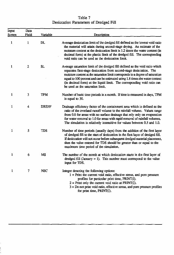
Table 7 Desiccation Parameters of Dredged Fill
Input Screen
Data Field Variable Description
1 1 DL Average desiccation limit of the dredged fill defined as the lowest void ratio the material will attain during second-stage drying. An estimate of the moisture content at the desiccation limit is 1.2 times the water content (in decimal form) at the plastic limit of the dredged fill. The corresponding void ratio can be used as the desiccation limit.
1 2
1 3
1 4
1 5 TDS
1 6 MS
1 7 NSC
SL Average saturation limit of the dredged fill defined as the void ratio which separates f&t-stage desiccation from second-stage desiccation. The moisture content at the saturation limit corresponds to a degme of saturation equal to 100 percent and can be estimated using 1.8 times the water content (in decimal form) at the liquid limit. The corresponding void ratio can be used as the saturation limit.
TPM Number of basic time periods in a month. If time is measured in days, TPM is equal to 30.
DREFF Drainage efficiency factor of the containment area which is defined as the ratio of the overland runoff volume to the rainfall volume. Values range from 0.0 for areas with no surface drainage that rely only on evaporation for water removal to 1 .O for areas with rapid removal of rainfall volumes. The simulation is relatively insensitive for values between 0.5 and 1.0.
Number of time periods (usually days) from the addition of the first layer of dredged fill to the start of desiccation in the first layer of dredged fill. If desiccation will not occur before subsequent dredged material placement, then the value entered for TDS should be greater than or equal to the maximum time period of the simulation.
The number of the month at which desiccation starts in the first layer of dredged fill (January = 1). This number must c0rrespon.d to the value input for TDS.
Integer denoting the following options: 1 = Print the current void ratio, effective stress, and pore pressure
profiles for particular print time, PRINT(I). 2 = Print only the current void ratio at PRINT(I). 3 = Do not print void ratio, effective stress, and pore pressure profiles
for print time, PRINT(I).

Table 8 Evaporation and Precipitation Data
Input Screen
Data Field Variable Description
1 1 PEP(I) Monthly class A pan or maximum environmental potential evaporation expected at the containment area each month of the year. January is month 1. Average monthly values of PEP and RF can be obtained from the US Weather Bureau records of climatic data.
1 2. Rw Average monthly rainfall expected at the containment area for each month of the year. January is month 1.
Table 9 Final Dredged Fill Desiccation Parameters
Input Screen
Data Field Variable Description
1 1 CE The maximum dredged fiil evaporation efficiency for desiccation drying. Observed values range from 0.5 to 1.2; however, the simulation is relatively insensitive to variations in CE between 0.5 and 1.0. Unless data are available, a value of 1.0 is recommended.
1 2 SAT The average degree of saturation, expressed as a fraction of 1.0, of the dredged fill when dried to the desiccation limit, DL. This value includes the crack network.
1 3 H2 The maximum depth to which second-stage drying will occur.
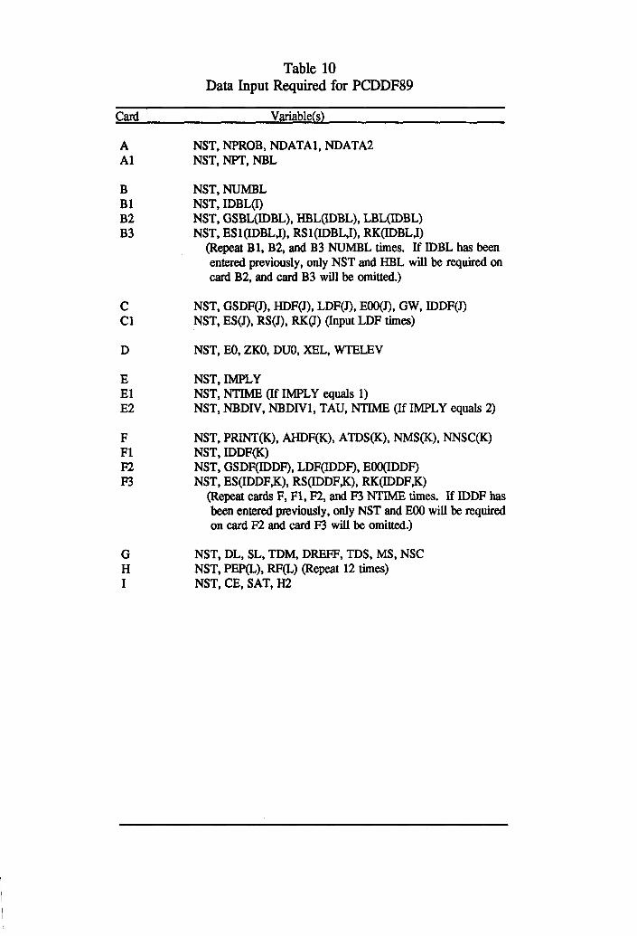
Table 10 Data Input Required for PCDDF89
Card Variable(s)
A NST, NPROB, NDATAl, NDATA2 Al NST, NPT, NBL
B Bl B2 B3
NST, NUMBL NST, IDBL(I) NST, GSBL(IDBL), HEL(IDBL), LBL(IDBL) NST, ESl(IDBL,I), RSl(IDBL,I), RK(IDBL,I)
&peat Bl, B2, and B3 NUMBL times. If IDBL has been entered previously, only NST and HBL will be required on card B2, and card B3 will be omitted.)
C Cl
NST, GSDF(J), HDF(J), LDF(J), EOO(J), GW, IDDF(J) NST, ES(J), RS(J), RK(J) (Input LDF times)
D NST, EO, ZKO, DUO, XEL, WTELEV
E El E2
NST, IMPLY NST, NTIME (If IMPLY equals 1) NST, NBDIV, NBDIVl, TAU, NTIME (If IMPLY equals 2)
F Fl F2 F3
NST, PRINT(K), AHDF(K), ATDS(K), NMS(K), NNSC(K) NST, IDDF(K) NST, GSDF(IDDF), LDF(IDDF), EOO(IDDF) NST, ES(IDDF,K), RS(IDDF,K), RK(IDDF,K)
(Repeat cards F, Fl, F2, and F3 NTIME times. If IDDF has been entered previously, only NST and EOO will be required on card F2 and card F3 will be omitted.)
G H I
NST, DL, SL, TDM, DREFF, TDS, MS, NSC NST, PEP(L), RF(L) (Repeat 12 times) NST, CE, SAT, I-I2

Table 11 Restart Program Execution Data
Input Data Screen Field Variable Descrimion
1 :1 NDATAl Integer denoting following options: 1 = new simulation.
1 2 NDATA2
2 = restart previous simulation (NDATAl should equal 2).
Integer denoting following options: 1 = output not saved in a continuation file for subsequent restart of
simulation. 2 = output saved in a continuation file for subsequent restart of
simulation.
1 3 NRROB
2 Ii MTIME
Description of simulation which can be a maximum of any 40 characters except a single quote, i.e., ‘.
Number of output or print times during restart of previous simulation.
Table 12 Restart Dredged Fill Data From Previous Simulation
Input D,ata Screen Field Variable Descrintion
1 I. AHDF(NTIME) Initial thickness of last dredged fill layer placed in the previous simulation.
1 Z! ATDS(NTIME) Cumulative number of time periods (usually days) from the addition of the first dredged fill layer to the start of desiccation in the last fill layer placed in the previous simulation.
1 7 _I NMS(NTIME) The number of the month at which desiccation starts for this dredged fill layer (January = 1).
1 4 NNSqNTIME) Integer denoting the following options: 1 = Print current void ratio, effective stress, and pore pressure
profiles. 2 = Print only current void ratio profile. 3 = Do not print current void ratio, effective stress, and pore
pressure profiles.

Table 13 Restart Print Times and New Dredged Fill Layer Data
Input Data Screen Field Variable Description
1 1 PRINW
1 2 AHDF(I)
1 3 ATDS(I)
2
3
5
1 IDDF
1 EOO(IDDF)
I ES(lDDF,I)
2
3
NMS
NNsqI)
GSDF(IDDF)
LDF(IDDF)
RS(IDDF,I)
Times at which the properties of the consolidating layers will be printed and/or a new layer of dredged fill is applied. PRINT’(I) should be expressed in cumulative number of time periods (usually days) from the addition of the first layer of dredged fill. This screen will be repeated NTIME times.
Jnitial thickness of new dredged fill layer to be added at PRINT(l). I f no additional dredged fill is being added, AHDF(J) is set to zero. If AHDF(I) is greater than zero, the material identification number and prcpetties must be entered.
Cumulative number of time periods (usually days) from the addition of the first layer of dredged fill to the start of desiccation in the dredged fill placed at PRINT(I). I f desiccaticm will not occur during the entire simulation. a value of ATDS greater than or equal to the maximum time period of the simulation should be entered.
The number of the month at which desiccation starts for this print time (January = 1). This number must correspond to the value input for ATDS.
Integer denoting the following options: 1 = Print the current void ratio. effective stress, and pore pressure profiles for print time,
PRINT(I). 2 = print only the current void ratio profile at PRlNT(l). 3 = Do not print void ratio, effective stress, and pore pressure profiles for print time,
PRINT(I).
Material identification number for the dredged fill added at PRINT(I). I f IDDF is the same as a previous layer. only EOO will be required in screen 3 and the other prcpetties will be loaded automatically from data entered previously. I f IDDF has not been used previously, the user will ship screen 3 and be prompted for the material properties in scmens 4 and 5.
Initial void ratio of new dredged fill after sedimentation and before consolidation. (Void ratio at top of self-weight consolidation test specimen at end of test; values usually range from 6 to 13.)
Specific gravity of the soil solids for new dredged fill material.
Number of data points used to describe the void ratio-effective stress and permeability-void ratio relationships of the new dredged material.
Initial void ratio of new dredged fill after sedimentation and before consohdation. (Void ratio at top of self-weight consolidaticn test specimen at end of tess values usually range from 6 to 13.)
Measured void ratio of new dredged fii layer under effective stresses applied in laboratory consolidation tests (self-weight consolidaticm test and/or standard oedometer test). Repeat LDF times. (See paragraph 53.)
Effective stresses applied in laboratory consolidation tests cormsponding to the void ratios entered above. Repeat LDF times.
Penneabilities from laboratory consolidation tests on the new dredged fill layer corresponding to the void ratios entered above. Repeat LDF times.
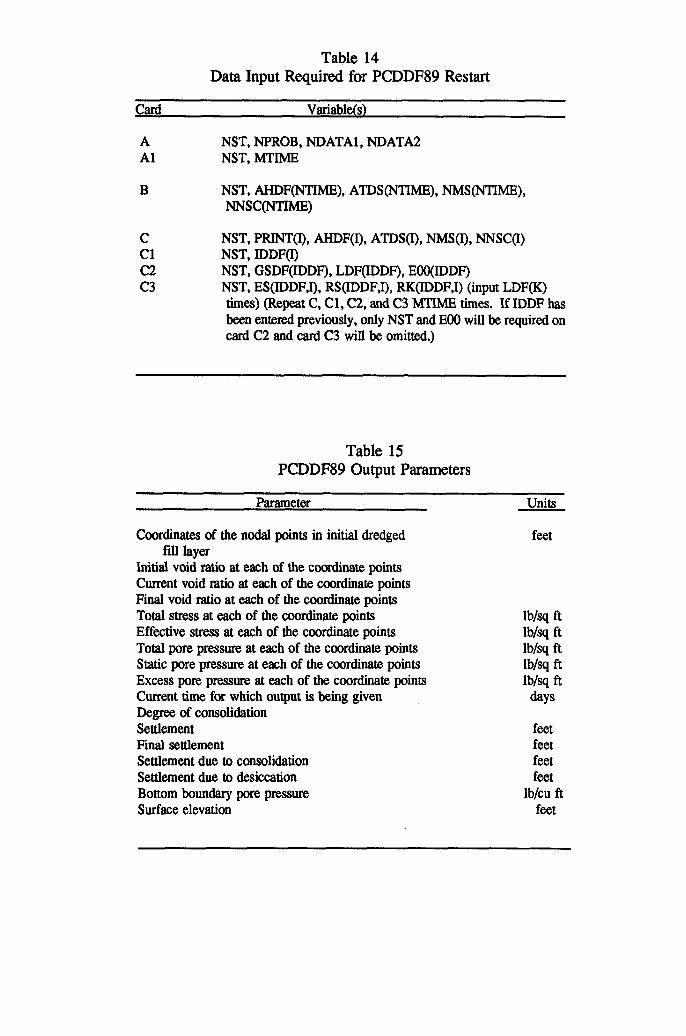
Table 14 Data Input Required for PCDDF89 Restart
Card Variable(s)
A NST, NPROB, NDATAl, NDATAZ Al NST, MTIME
B NST, AHDFWIIME), ATDS(NTIME), NMS(NTIME), NNSC(NTIME)
C Cl c2 c3
NST, PRINT(I), AHDF(I), ATDS(I), NMS(I), NNSC(I) NST, IDDF(I) NST, GSDF(IDDF), LDF(IDDF), EOO(IDDF) NST, ES(IDDF,I), RS(IDDF,I), RK(IDDF.1) (input LDF(K) times) (Repeat C, Cl, C2, and C3 MTIME times. If IDDF has been entered previously, only NST and EOO will be required on card C2 and card C3 will be omitted.)
Table 15 PCDDF89 Output Parameters
Parameter
Coordinates of the nodal points in initial dredged fiII layer
Initial void ratio at each of the coordinate points Current void ratio at each of the coordinate points Final void ratio at each of the coordinate points Total stress at each of the coordinate points Effective stress at each of the coordinate points Total pore pressure at each of the coordinate points Static pore pressure at each of the coordinate points Excess pore pressure at each of the coordinate points Current time for which output is being given Degree of consolidation Settlement Final settlement Settlement due to consolidation Settlement due to desiccation Bottom boundary pore pressure Surface elevation
Units
feet
lb/sq ft lblsq ft lb/sq ft lbisq ft lb/sq ft &YS
feet feet feet feet
lb/cu ft feet
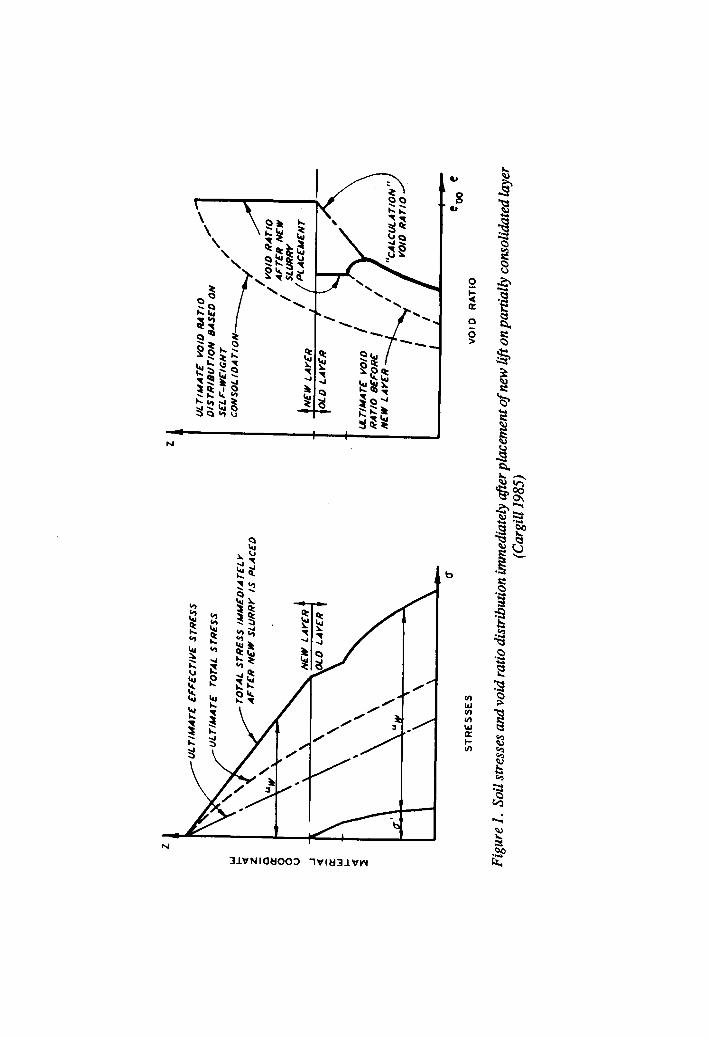
UL
TIM
ATE
EFFE
CTf
YE
STRE
SS
UL
TIM
A TE
TO
TAL
S TR
ESS
TOTA
L ST
RESS
fA
dMED
IA
TL
Y AF
TER
NEW
SL
URRY
IS
PL
ACED
STRE
SSES
ULTI
MAT
E VO
fD
RATI
O ,
DfST
RfBU
TfON
8A
SED
ON
/’
SELF
-WEf
GHT
/ /
CONS
OL
f DA
Tf O
N
b/ P
P
/ /
/- VO
fD
RATI
O AF
TER
NEW
/
SLUR
RY
c
VOID
RA
TIO
Figu
re I
. So
il st
ress
es an
d vo
id ra
tio d
istri
butio
n im
med
kzte
ly @
er p
lace
men
t of n
ew li
ft on
par
tially
co
nsol
idat
ed ta
yer
(Car
gill
1985
)

100 'Ex.l-Compressible Found. & 2 Matl. Types' 1 2 101 1 1 102 1 103 3 104 2.83 10 7 105 2.5 12.0 .601E-03 106 2.45 40.0 .5343-03 107 2.38 100.0 .4523-03 108 2.26 200.0 .3383-03 109 2.0 500.0 .1733-03 110 1.82 1000.0 .106E-03 111 1.68 2000.0 .7063-04 112 2.6 6.0 36 12.15 62.4 1 113 12.15 O.OOE-00 1.56E-01 114 12.00 5.80E-02 1.44E-01 115 11.50 1.68E-01 l.l2E-01 116 11.00 3.563-01 8.71E-02 117 10.50 6.60E-01 6.77E-02 118 10.00 l.l2E+OO 5.27@-02 119 9.70 1.50E+OO 4.583-02 120 9.30 2.20E+OO 3.743-02 121 9.00 2.86E+OO 3.233-02 122 8.70 3.68E+OO 2.76E-02 123 8.30 4.90E+OO 2.29E-02 124 8.00 6.04E+OO 1.943-02 125 7.75 7.16E+OO 1.71E-02 126 7.50 8.36E+OO 1.47E-02 127 7.25 9.80E+OO 1.27E-02 128 7.00 l.l‘4E+Ol l.lOE-02 129 6.75 1.33E+Ol 9.363-03 130 6.50 1.54E+Ol 7.92E-03 131 6.25 17.9 6.62E-03 132 6.00 21.8 5.573-03 133 5.75 28.6 4.54E-03 134 5.5 40.2 3.643-03 135 5.25 57.0 2.87E-03 136 5.0 78.6 2.223-03 137 4.75 111.0 1.66E-03 138 4.5 153.0 1.253-03 139 4.25 216.0 9.00E-04 140 4.0 300.0 6.48E-04 141 3.75 420.0 4.57E-04 142 3.5 590.0 3.20E-04 143 3.25 820.0 2.173-04 144 3.0 1140.0 1.48E-04 145 2.75 1580.0 9.793-05 146 2.5 2200.0 6.62E-05 147 2.25 3100.0 4.39E-05 148 2.0 4240.0 2.97E-05 149 1. l.OE-06 10. 100. 0. 150 1 151 4 152 90 0 90 4 1 153 180 0 180 7 1
Figure 2. Example I: Input data file (Continued)
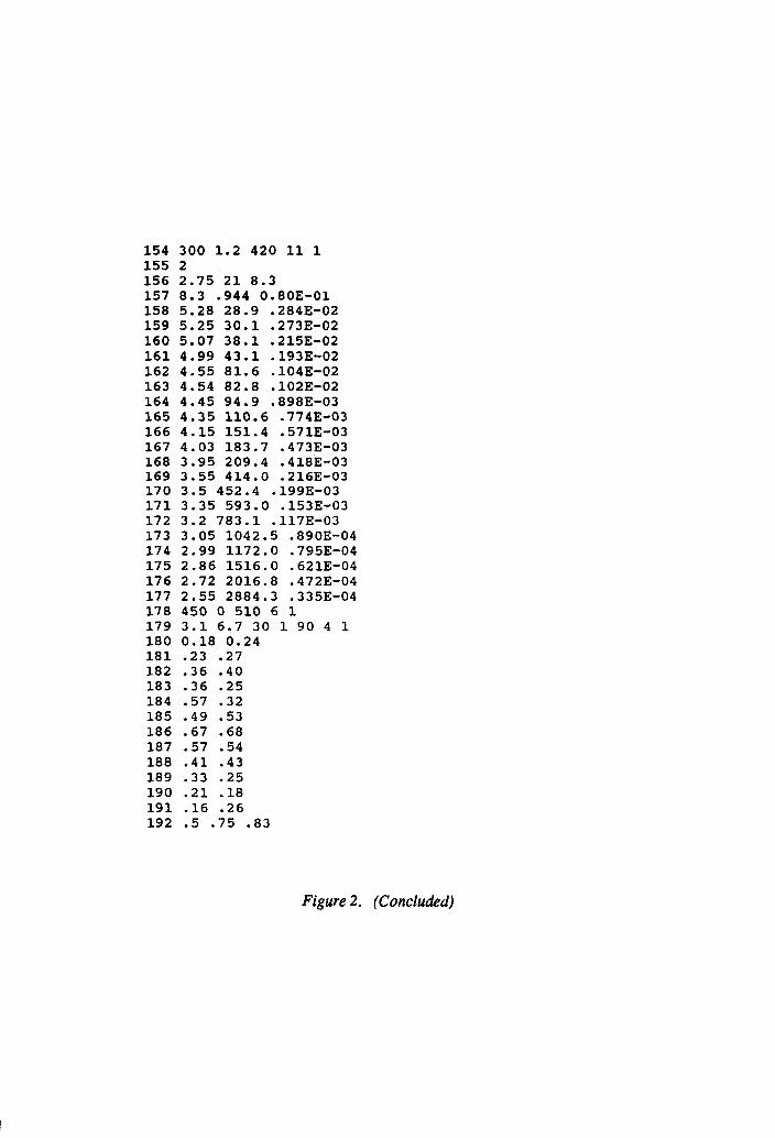
154 300 1.2 420 11 1 155 2 156 2.75 21 8.3 157 8.3 -944 0.80E-01 158 5.28 28.9 .2843-02 159 5.25 30.1 .2733-02 160 5.07 38.1 .215E-02 161 4.99 43.1 .1933-02 162 4.55 81.6 .104E-02 163 4.54 82.8 .102E-02 164 4.45 94.9 .8983-03 165 4.35 110.6 .774E-03 166 4.15 151.4 .5713-03 167 4.03 183.7 .4733-03 168 3.95 209.4 .4183-03 169 3.55 414.0 .2163-03 170 3.5 452.4 .1993-03 171 3.35 593.0 .1533-03 172 3.2 783.1 .117E-03 173 3.05 1042.5 .8903-04 174 2.99 1172.0 .7953-04 175 2.86 1516.0 .6213-04 176 2.72 2016.8 .4723-04 177 2.55 2884.3 .3353-04 178 450 0 510 6 1 179 3.1 6.7 30 1 90 4 1 180 0.18 0.24 181 .23 .27 182 .36 .40 183 . 36 .25 184 .57 .32 185 .49 .53 186 .67 .68 187 .57 .54 188 .41 .43 189 .33 .25 190 .21 .18 191 -16 .26 192 .5 .75 .83
Figure 2. (Concluded)

************************************************************ CONSOLIDATION AND DESICCATION OF SOFT LAYERS---DREDGED FILL ************************************************************
PROBLEM Ex.l-Compressible Found. & 2 Matl. Types
******************SOIL DATA FOR COMPRESSIB~ FOUNDATION*********+*******
MATERIAL TYPE
LAYER THICKNESS
SPECIFIC GRAVITY OF SOLIDS
3 10.00 2.83
‘VOID EFFECTIVE RFLTIO STRESS 2.500 . 120E+02 2.450 . 400E+02 2.380 . lOOE+03 2.260 . 200E+03 2.000 . 500E+03 1.820 . lOOE+04 1.680 . 200E+04
PERM- K/l+E EABILITY PK
:5343-03 601E-03 :1553-03 172E-03
13383-03 4523-03 :104E-03 1343-03
. 1733-03 .5773-04
. 106E-03 .3763-04
. 7063-04 .2633-04
BETA DSDE ALPHA . 339E-03 -.560E+03 -.962E-01 . 3173-03 -.733E+03 -.114E+OO .269E-03 -.842E+03 -.113E+OO . 200E-03 -.105E+04 -.109E+OO . 150E-03 -.182E+04 -.105E+OO . 979E-04 -.4693+04 -.176E+OO * 8033-04 -.714E+04 -.188E+oo
Figure 3. Example 1: Output (Sheet 1 of 15)

***********************SOIL DATA FOR DREDGED FILL+**********************
LAYER SPECIFIC GRAVITY INITIAL SATURATION DESICCATION THICKNESS OF SOLIDS VOID RATIO LIMIT LIMIT
6.00 2.60 12.15 6.70 3.10
MATERIAL TYPE 1
VOID EFFECTIVE I RATIO STRESS 1 12.150 .OOOE+OO 2 12.000 .580E-01 3 11.500 . 168E+oo 4 11.000 . 3563+00 5 10.500 . 660E+oo 6 10.000 . 112E+Ol 7 9.700 . 150E+Ol 8 9.300 .220E+Ol 9 9.000 . 286E+Ol
10 8.700 .3683+01 11 8.300 . 490E+Ol 12 8.000 . 604E+Ol 13 7.750 . 716E+Ol 14 7.500 .8363+01 15 7.250 . 980E+Ol 16 7.000 . 114E+02 17 6.750 . 133E+02 18 6.500 . 154E+02 19 6.250 . 179E+02 20 6.000 .218E+02 21 5.750 .2863+02 22 5.500 .402E+02 23 5.250 .570E+02 24 5.000 . 7863+02 25 4.750 . lllE+03 26 4.500 . 1533+03 27 4.250 . 2163+03 28 4.000 . 300E+03 29 3.750 .4203+03 30 3.500 . 590E+03 31 3.250 .8203+03 32 3.000 . 114E+04 33 2.750 . 1583+04 34 2.500 .220E+04 35 2.250 . 310E+04 36 2.000 . 4243+04
PERM- EABILITY
.156E+OO
.144E+OO
. 112E+OO
.871E-01
. 6773-01
. 5273-01
. 4583-01
. 3743-01 323E-01
12763-01 .229E-01
194E-01 :171E-01
147E-01 :127E-01
llOE-01 :9363-02 .792E-02 . 662E-02 . 5573-02 . 4543-02
364E-02 :287~-02 -2223-02
1663-02 :1253-02 . 900E-03 . 6483-03 -4573-03 . 320E-03
2173-03 :1483-03 . 9793-04 . 6623-04 . 439E-04 . 297E-04
K/l+E PK
. 119E-01
. lllE-01
.896E-02
. 726E-02
.589E-02
.479E-02
. 428E-02
. 363E-02
. 323E-02
.285E-02
.246E-02
. 216E-02 195E-02
:173E-02 . 154E-02 137E-02
:121E-02 . 106E-02 . 913E-03 . 796E-03
673E-03 :560~-03
459E-03 :370E-03 . 289E-03 . 227E-03 . 171E-03 .130E-03 .962E-04 . 711E-04
511E-04 :370E-04 . 261E-04
189E-04 :135E-04 . 990E-05
BETA DSDE ALPHA .5243-02 -.387E+OO -.4593-02 . 4473-02 -.258E+OO -.2863-02 . 382E-02 -.298E+OO -.267E-02 . 3073-02 -.4923+00 -.357E-02 . 247E-02 -.7643+00 -44503-02 . 201E-02 -.105E+Ol -.503E-02 . 1663-02 -.154E+Ol -.660E-02 . 150E-02 -.194E+Ol -.7053-02 . 131E-02 -.2473+01 -.7973-02 . llOE-02 -.291E+Ol -.829E-02 .9853-03 -.337E+Ol -.830E-02 . 9243-03 -.411E+Ol -.8863-02 . 852E-03 -.464E+Ol -.9073-02 . 830E-03 -.5283+01 -.9133-02 . 7093-03 -.608E+Ol -.9363-02 . 6633-03 -.700E+Ol -.962E-02 . 6383-03 -.800E+Ol -.9663-02 . 589E-03 -.920E+Ol -.972E-02 . 521E-03 -.1283+02 -.117E-01 . 4813-03 -.214E+02 -.170E-01 . 4713-03 -.368E+02 -.248E-01 . 427E-03 -.568E+02 -.318E-01 . 380E-03 -.768E+02 -.353E-01 . 3413-03 -.108E+03 -.400E-01 .285E-03 -.149E+03 -.430E-01 2353-03
:1953-03 -.210E+03 -.477E-01 -.2943+03 -.504E-01
. 150E-03 -.4083+03 -.529E-01
. 117E-03 -.580E+03 -.5583-01
. 903E-04 -.800E+03 -.569E-01
. 682E-04 -.llOE+04 -.562E-01
. 499E-04 -.152E+04 -.562E-01
. 362E-04 -.2123+04 -.553E-01
. 2523-04 -.304E+04 -.5753-01
. 180E-04 -.408E+04 -.551E-01
. 144E-04 -.4563+04 -.451E-01
Figure 3. (Sheet 2 of 15)
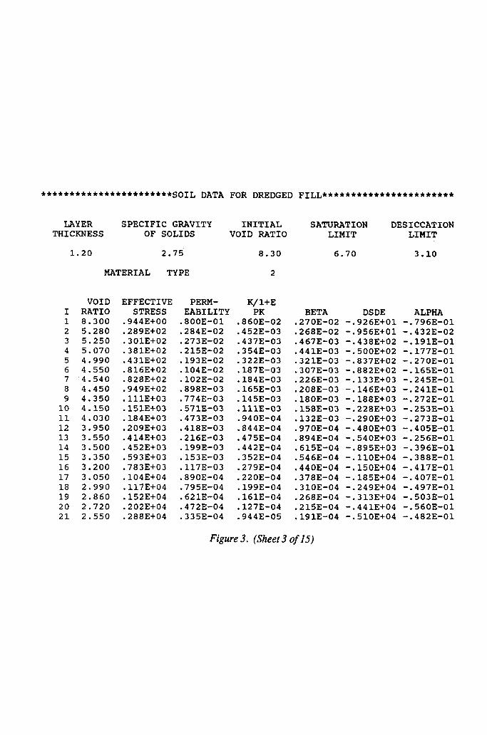
***********************SOIL DATA FOR DREDGED FILL***********************
LAYER SPECIFIC GRAVITY INITIAL SATURATION DESICCATION THICKNESS OF SOLIDS VOID RATIO LIMIT LIMIT
1.20 2.75 8.30 6.70 3.10
MATERIAL TYPE 2
I 1 2 3 4 5 6 7 8 9
10 11 12 13 14 15 16 17 18 19 20 21
VOID EFFECTIVE RATIO STRESS 8.300 . 944E+OO 5.280 .289E+02 5.250 . 301E+02 5.070 . 381E+02 4.990 .431E+02 4.550 .816E+02 4.540 .828E+02 4.450 .9493+02 4.350 . lllE+03 4.150 . 15lE+03 4.030 . 184E+03 3.950 .2093+03 3.550 . 414E+03 3.500 .4523+03 3.350 . 593E+03 3.200 .783E+03 3.050 . 104E+04 2.990 . 117E+04 2.860 . 152E+04 2.720 . 202E+04 2.550 . 2886+04
PERM- EABILITY
.800E-01
.2843-02
. 2733-02
. 2153-02
. 193E-02 104E-02
:102E-02 .898E-03 . 7743-03 -5713-03 . 4733-03 . 418E-03 .2163-03 . 1993-03 . 153E-03 . 117E-03 .890E-04 . 7953-04 .621E-04 . 472E-04 . 3353-04
K/l+E PK
.8603-02
.452E-03
.437E-03
. 3543-03
. 3223-03 1873-03
1 i84E-03 1653-03
:145E-03 .lllE-03 .9403-04 .8443-04 .475E-04
4423-04 :3523-04 .279E-04 .2203-04 . 1993-04 . 161E-04 127E-04
19443-05
BETA DSDE ALPHA .2703-02 -.926E+Ol -.7963-01 .268E-02 -.956E+Ol -.4323-02 . 4673-03 -.4383+02 -.191E-01 . 4413-03 -.500E+02 -.177E-01 . 32lE-03 -.837E+02 -.270E-01 .3073-03 -.882E+02 -.165E-01 .226E-03 -.133E+03 -.2453-01 . 2083-03 -.146E+03 -.241E-01 . 180E-03 -.188E+O3 -.2723-01 . 158E-03 -.2283+03 -.2533-01 . 1323-03 -.2903+03 -.2733-01 . 9703-04 -.4803+03 -.405E-01 . 8943-04 -.540E+03 -.2563-01 . 6153-04 -.895E+03 -.396E-01 .5463-04 -.llOE+04 -.388E-01 . 4403-04 -.150E+04 -.417E-01 . 3783-04 -.185E+04 -.407E-01 . 310E-04 -.249E+04 -.4973-01 .2683-04 -.313E+04 -.503E-01 .2153-04 -.441E+04 -.560E-01 . 191E-04 -.510E+04 -.482E-01
Figure 3. (Sheet 3 of 15)

SUMMARY OF MONTHLY RAINFALL AND EVAPORATION POTENTIAL
MONTH
1
2
3
4
5
6
7
8
9
10
11
12
RAINFALL
.240
.270
.400
EVAPORATION
. 250
. 320
-530
. 680
.540
. 180
.230
. 360
. 360
. 570
.490
.670
. 430
.250
. 180
. 570
. 410
. 330
.210
. 260 . 160
*********************++*******CALCU~TION DATA********************+*********
TAU LOWER LAYER LOWER LAYER DRAINAGE: PATH VOID RATIO PERMEABILITY LENGTH
. 500 1.000 . lOOOOE-05 Z= 5.00
Figure 3. (Sheet 4 of 15)
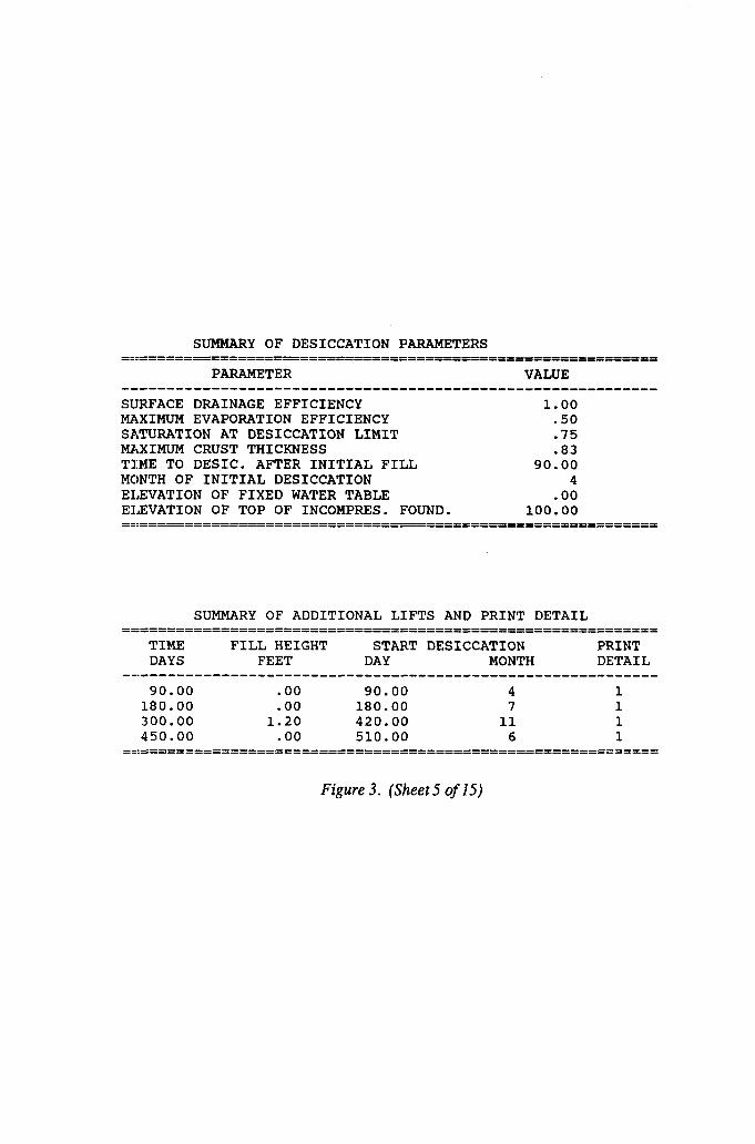
SUMMARY OF DESICCATION PARAMETERS ==IZ=========================================================
PARAMETER VALUE
SIJRFACE DRAINAGE EFFICIENCY 1.00 MAXIMUM EVAPORATION EFFICIENCY .50 SATURATION AT DESICCATION LIMIT .75 MAXIMUM CRUST THICENESS .a3 TIME TO DESIC. AFTER INITIAL FILL 90.00 MCJNTH OF INITIAL DESICCATION 4 ELEVATION OF FIXED WATER TABLE .oo ELEVATION OF TOP OF INCOMPRES. FOUND. 100.00 ==:=============================o===============================
SUMMARY OF ADDITIONAL LIFTS AND PRINT DETAIL ==:=============================P===============================
TIME FILL HEIGHT START DESICCATION PRINT DAYS FEET DAY MONTH DETAIL
-_---------------------------------------------------------- 90.00 . 00 90.00 4 1
180.00 . 00 180.00 7 1 300.00 1.20 420.00 11 1 450.00 . 00 510.00 6 1
==:==========================================================
Figure 3. (Sheet 5 of 15)
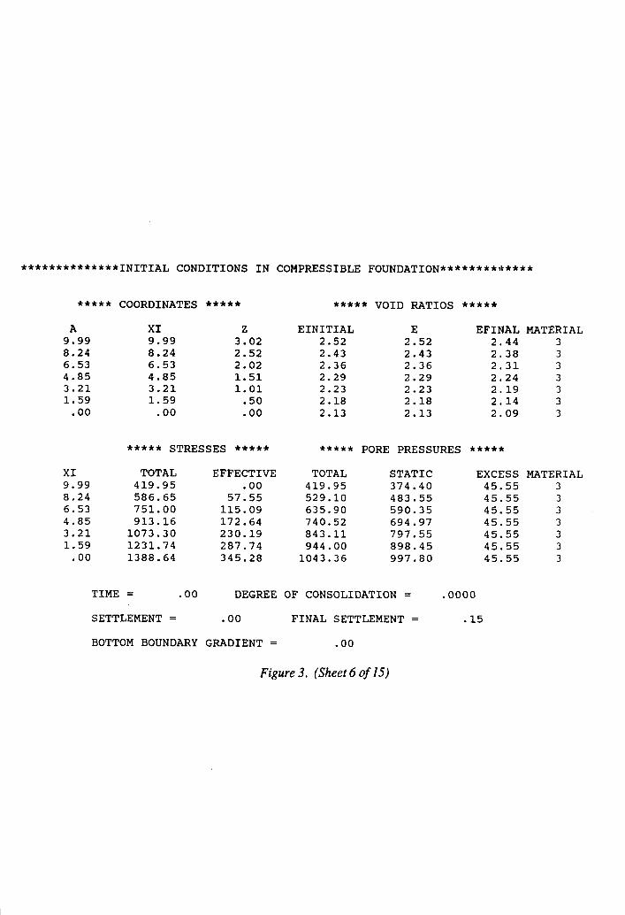
**************INITIAL CONDITIONS IN COMPRESSIBLE FOUNDATION*************
***** COORDINATES ***** ***** VOID RATIOS *****
A XI z EINITIAL E EFINAL MATERIAL 9.99 9.99 3.02 2.52 2.52 2.844 3 8.24 8.24 2.52 2.43 2.43 2.38 3 6.53 6.53 2.02 2.36 2.36 2.31 3 4.85 4.85 1.51 2.29 2.29 2.24 3 3.21 3.21 1.01 2.23 2.23 2.19 3 1.59 1.59 . 50 2.18 2.18 2.14 3
. 00 . 00 .oo 2.13 2.13 2.09 3
***** STRESSES ***** ***** PORE PRESSURES ****jr
XI TOTAL EFFECTIVE TOTAL STATIC EXCESS MATERIAL 9.99 419.95 . 00 419.95 374.40 45.55 3 8.24 586.65 57.55 529.10 483.55 45.55 3 6.53 751.00 115.09 635.90 590.35 45.55 3 4.85 913.16 172.64 740.52 694.97 45.55 3 3.21 1073.30 230.19 843.11 797.55 45.55 3 1.59 1231.74 287.74 944.00 898.45 45.55 3
. 00 1388.64 345.28 1043.36 997.80 45.55 3
TIME = . 00 DEGREE OF CONSOLIDATION = .OOOO
SETTLEMENT = . 00 FINAL SETTLEMENT = . 15
BOTTOM BOUNDARY GRADIENT = . 00
Figure 3. (Sheet 6 of 15)

**X*****+**k*******INITIAL CONDITIONS IN DREDGED FILL********+**********
***,I* COORDINATES ***** ***** VOID RATIOS *****
A XI z EINITIAL E EFINAL MATERIAL 6.00 6.00 46 12.15 12.15 12.15 1 5.25 5.25 :40 12.15 12.15 8.09 1 4.50 4.50 .34 12.15 12.15 7.00 1 3.75 3.75 .29 12.15 12.15 6.33 1 3.00 3.00 .23 12.15 12.15 5.96 1 2.25 2.25 . 17 12.15 12.15 5.75 1 1.50 1.50 . 11 12.15 12.15 5.63 1
.75 .75 .06 12.15 12.15 5.51 1
. 00 . 00 . 00 12.15 12.15 5.42 1
***** STRESSES ***** ***** PORE PRESSURES *****
XI TOTAL EFFECTIVE TOTAL STATIC EXCESS MATERIAL 6.00 . 00 . 00 . 00 .oo .oo 1 5.25 52.49 00 52.49 46.80 5.69 1 4.50 104.99 :oo 104.99 93.60 11.39 1 3.75 157.48 . 00 157.48 140.40 17.08 1 3.00 209.98 . 00 209.98 187.20 22.78 1 2.25 262.47 00 262.47 234.00 28.47 1 1.50 314.97 :oo 314.97 280.80 34.17 1
-75 367.46 .oo 367.46 327.60 39.86 1 . 00 419.95 .oo 419.95 374.40 45.55 1
TIME = . 00 DEGREE OF CONSOLIDATION = .OOOO
SETTLEMENT = . 00 FINAL SETTLEMENT = 2.55
BOTTOM BOUNDARY GRADIENT = .oo
Figure 3. (Sheet 7 of 15)

**************CURRENT CONDITIONS IN COMPRESSIBLE FOUNDATION*************
***** COORDINATES ***** ***** VOID RATIOS *****
A XI z EINITIAL E EFINAL MATERIAL 9.99 9.98 3.02 2.52 2.50 2.44 3 8.24 8.24 2.52 2.43 2.42 2.38 3 6.53 6.53 2.02 2.36 2.36 2.31 3 4.85 4.85 1.51 2.29 2.29 2.24 3 3.21 3.21 1.01 2.23 2.24 2.19 3 1.59 1.59 .50 2.18 2.18 2.14 3
. 00 . 00 .oo 2.13 2.13 2.09 3
it**** STRESSES ****+ ***** PORE PRESSURES *****
XI TOTAL EFFECTIVE TOTAL STATIC EXCElSS MATERIAL 9.98 327.67 14.64 313.03 282.12 30.92 3 8.24 494.01 61.72 432.29 390.90 41.39 3 6.53 658.20 118.41 539.79 497.55 42.24 3 4.85 820.32 171.98 648.34 602.12 46.22 3 3.21 980.50 228.67 751.82 704.75 47.07 3 1.59 1138.94 289.23 849.71 805.65 44.06 3
. 00 1295.80 345.28 950.52 904.96 45.55 3
TIME = 90.00 DEGREE OF CONSOLIDATION = .0607
SETTLEMENT = .Ol FINAL SETTLEMENT = . 15
BOTTOM BOUNDARY GRADIENT = .06
Figure 3. (Sheet 8 of 15)
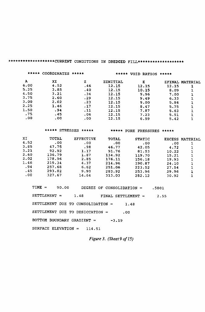
x**********jr*******CU~ENT CONDITIONS IN DREDGED FILL*******************
***jr* COORDINATES ***** ***** VOID RATIOS *****
A XI 6.00 4.52 5.25 3.85 4.50 3.21 3.75 2.60 3.00 2.02 2.25 1.46 1.50 .94
.75 .45
. 00 . 00
2 EINITIAL E EFINAL MATERIAL .46 12.15 12.15 12.15 1 . 40 12.15 10.15 8.09 1 . 34 12.15 9.96 7.00 1 . 29 12.15 9.49 6.33 1 .23 12.15 9.00 5.96 1 . 17 12.15 8.47 5.75 1 . 11 12.15 7.87 5.63 1 . 06 12.15 7.23 5.51 1 . 00 12.15 6.59 5.42 1
+***+ STRESSES ***** ***** PORE PRESSURES *****
XI TOTAL EFFECTIVE TOTAL STATIC EXCESS MATERIAL 4.52 00 3.85 47:75
. 00 . 00 . 00 . 00 1
. 98 46.77 42.05 4.72 1 3.21 92.92 1.17 91.76 81.53 10.22 1 2.60 136.79 1.87 134.92 119.70 15.21 1 2.02 178.96 2.85 176.11 156.18 19.93 1 1.46 219.34 4.37 214.96 190.87 24.10 1
.94 257.68 6.62 251.06 223.52 27.54 1
. 45 293.82 9.90 283.92 253.96 29.96 1
. 00 327.67 14.64 313.03 282.12 30.92 1
TIME = 90.00 DEGREE OF CONSOLIDATION =
SE:TTLEMENT = 1.48 FINAL SETTLEMENT =
SE:TTLEMENT DUE TO CONSOLIDATION = 1.48
SE:TTLEMENT DUE TO DESICCATION = . 00
BOTTOM BOUNDARY GRADIENT = -3.19
SURFACE ELEVATION = 114.51
Figure 3. (Sheet 9 of 15)
5801
2.55
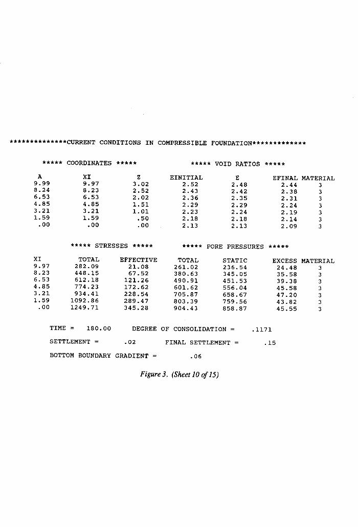
**************CURRENT CONDITIONS IN COMPRESSIBLE FOUNDATION*************
***** COORDINATES ***** ***** VOID RATIOS *****
A XI Z EINITIAL E EFINAL MATERIAL 9.99 9.97 3.02 2.52 2.48 2.44 3 8.24 8.23 2.52 2.43 2.42 2.38 3 6.53 6.53 2.02 2.36 2.35 2.31 3 4.85 4.85 1.51 2.29 2.29 2.24 3 3.21 3.21 1.01 2.23 2.24 2.19 3 1.59 1.59 . 50 2.18
-00 2.18 2.14 3
. 00 . 00 2.13 2.13 2.09 3
***** STRESSES *ff** ***** PORE PRESSURES *****
XI TOTAL EFFECTIVE TOTAL STATIC EXCESS MATERIAL 9.97 282.09 21.08 261.02 236.54 24.48 3 8.23 448.15 67.52 380.63 345.05 35.58 3 6.53 612.18 121.26 490.91 451.53 39.38 3 4.85 774.23 172.62 601.62 556.04 45.58 3 3.21 934.41 228.54 705.87 1.59
658.67 47.20 3 1092.86 289.47 803.39
00 759.56 43.82 3
. 1249.71 345.28 904.43 858.87 45.55 3
TIME = 180.00 DEGREE OF CONSOLIDATION = .1171
SETTLEMENT = . 02 FINAL SETTLEMENT = . 15
BOTTOM BOUNDARY GRADIENT = . 06
Figure 3. (Sheet 10 of 15)

**********+a*******CU~ENT CONDITIONS IN DREDGED FILL+********+*+*******
***jr* COORDINATES ***** ***** VOID RATIOS *****
A XI 6.00 3.79 5.25 3.34 4.50 2.81 3.75 2.28 3.00 1.78 2.25 1.30 1.50 -84
.75 .41 . 00 . 00
XI 3.79 3.34 2.81 2.28 1.78 1.30
. 84
. 41
. 00
2 EINITIAL E EFINAL MATERIAL .46 12.15 6.70 12.15 1 .40 12.15 7.58 8.09 1 . 34 12.15 8.50 7.00 1 .29 12.15 8.05 6.33 1 .23 12.15 7.63 5.96 1 . 17 12.15 7.21 5.75 1 . 11 12.15 6.78 5.63 1 .06 12.15 6.36 5.51 1 . 00 12.15 6.05 5.42 1
***** STRESSES ****St ***** PORE PRESSURES *****
TOTAL EFFECTIVE TOTAL . 00 . 00 . 00
34.03 5.69 28.33 72.52 4.28 68.25
111.21 5.86 105.36 148.36 7.75 140.61 184.01 10.06 173.95 218.17 13.07 205.10 250.80 16.75 234.04 282.09 21.08 261.02
STATIC EXCESS MATERIAL -00 . 00 1
28.33 .oo 1 61.14 7.11 1 94.13 11.23 1
125.58 15.03 1 155.54 18.41 1 184.00 21.10 1 210.94 23.11 1 236.54 24.48 1
TIME = 180.00 DEGREE OF CONSOLIDATION =
SE:TTLEMENT = 2.21 FINAL SETTLEMENT =
SETTLEMENT DUE TO CONSOLIDATION = 1.96
SETTLEMENT DUE TO DESICCATION = . 25
BOTTOM BOUNDARY GRADIENT = -4.49
SURFACE ELEVATION = 113.77
Figure 3. (Sheet 1 I of 15)
. 7700
2.55
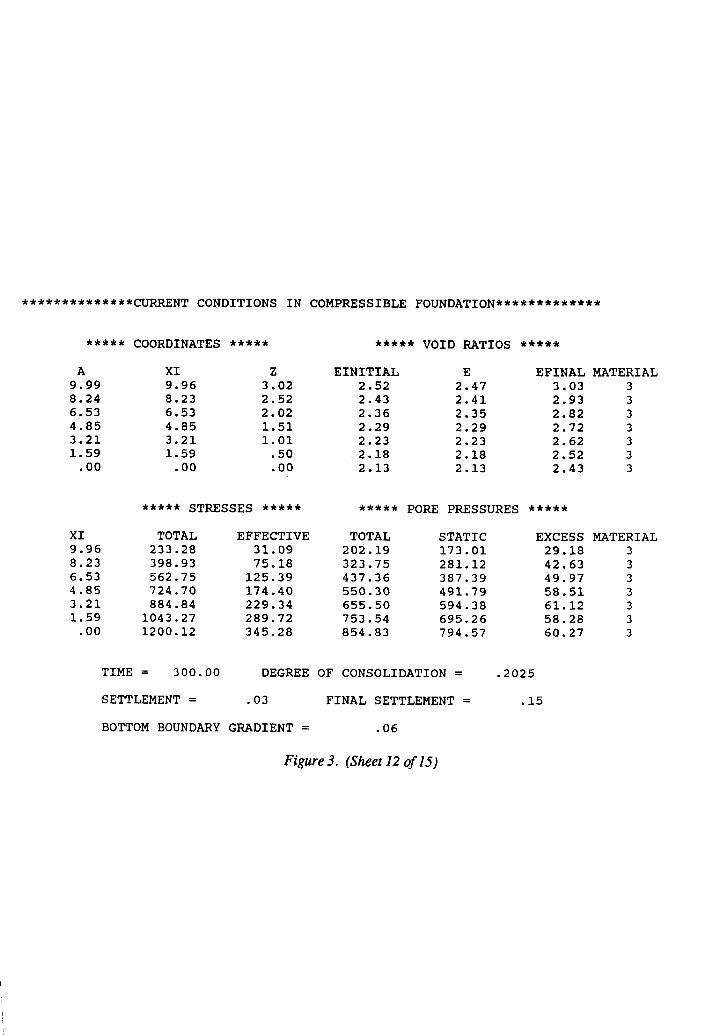
**************CURRENT CONDITIONS IN COMPRESSIBLE FOUNDATION*************
***** COORDINATES ***** ***** VOID RATIOS *****
A XI Z EINITIAL E EFINAL MATERIAL 9.99 9.96 3.02 2.52 2.47 3.03 3 8.24 8.23 2.52 2.43 2.41 2.93 3 6.53 6.53 2.02 2.36 2.35 2.82 3 4.85 4.85 1.51 2.29 2.29 2.72 3 3.21 3.21 1.01 2.23 2.23 2.62 3 1.59 1.59 .50 2.18 2.18 2.52 3
.oo .oo .oo 2.13 2.13 2.43 3
XI 9.96 8.23 6.53 4.85 3.21 1.59
. 00
*+*+* STRESSES +***f ***** PORE PRESSURES *****
TOTAL EFFECTIVE TOTAL STATIC EXCESS MATERIAL 233.28 31.09 202.19 173.01 29.18 3 398.93 75.18 323.75 281.12 42.63 3 562.75 125.39 437.36 387.39 49.97 3 724.70 174.40 550.30 491.79 58.51 3 884.84 229.34 655.50 594.38 61.12 3
1043.27 289.72 753.54 695.26 58.28 3 1200.12 345.28 854.83 794.57 60.27 3
TIME = 300.00 DEGREE OF CONSOLIDATION = .2025
SETTLEMENT = . 03 FINAL SETTLEMENT = . 15
BOTTOM BOUNDARY GRADIENT = . 06
Figure 3. (Sheet 12 of 15)
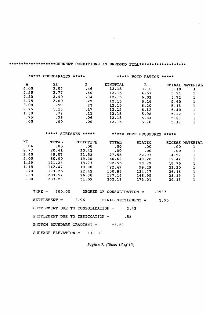
***********~k*******CU~ENT CONDITIONS IN DREDGED FILL****************+**
***:kf COORDINATES ***** ***** VOID RATIOS *****
A XI 6.00 3.04 5.25 2.77 4.50 2.40 3.75 2.00 3.00 1.59 2.25 1.18 1.50 -78
. 75
. 00 . 39 . 00
XI 3.04 2.77 2.40 2.00 1.59 1.18
78 :39 . 00
2 EINITIAL E EFINAL MATERIAL . 46 12.15 3.10 3.10 1 .40 12.15 4.57 5.91 1 -34 12.15 6.02 5.72 1 .29 12.15 6.16 5.60 1 . 23 12.15 6.20 5.48 1 .17 12.15 6.12 5.40 1 . 11 12.15 5.98 5.32 1 . 06 12.15 5.83 5.23 1 . 00 12.15 5.70 5.17 1
***** STRESSES +**** ***** PORE PRESSURES *****
TOTAL .oo
20.41 49.07 80.00
111.28 142.47 173.25 203.52 233.28
EFFECTIVE TOTAL STATIC . 00 . 00 . 00
20.41 .oo . 00 21.53 27.55 22.97 19.38 60.62 48.20 18.73 92.55 73.79 19.98 122.49 99.29 22.42 150.83 124.37 26.38 177.14 148.95 31.09 202.19 173.01
EXCESS MATERIAL .oo 1 .oo 1
4.57 1 12.42 1 18.76 1 23.20 1 26.46 1 28.19 1 29.18 1
TIME = 300.00 DEGREE OF CONSOLIDATION =
SETTLEMENT = 2.96 FINAL SETTLEMENT =
SETTLEMENT DUE TO CONSOLIDATION = 2.43
SETTLEMENT DUE TO DESICCATION = .53
BOTTOM BOUNDARY GRADIENT = -6.61
SlJRFACE ELEVATION = 113.01
Figure 3. (Sheet 13 of 15)
9537
2.55

**************CURRENT CONDITIONS IN COMPRESSIBLE FOUNDATION********t****
***** COORDINATES ***** ***** VOID RATIOS *****
A XI z EINITIAL E EFINAL MATERIAL 9.99 9.94 3.02 2.52 8.24
2.44 2.43 3 8.22 2.52 2.43 2.39 2.36 3
6.53 6.52 2.02 2.36 4.85
2.34 2.29 3 4.85 1.51 2.29
3.21 2.29 2.23 3
3.21 1.01 2.23 1.59
2.23 2.18 3 1.59 50 2.18
.oo 2.18 2.13
:oo 3
.oo 2.13 2.13 2.08 3
f**** STRESSES ***** ***** PORE PRESSURES *****
XI TOTAL EFFECTIVE TOTAL STATIC EXCESS MATERIAL 9.94 301.08 48.34 252.74 8.22
238.80 13.95 3 466.10 88.02 378.08
6.52 346.27 31.81 3
629.57 132.07 497.50 4.85
452.19 45.31 3 791.33 177.71 613.62 556.41 57.21 3
3.21 951.38 231.37 720.01 1.59
658.91 61.10 3 1109.78 290.45 819.33 759.76
.oo 59.57 3
1266.62 345.28 921.33 859.05 62.28 3
TIME = 450.00 DEGREE OF CONSOLIDATION = .2670
SETTLEMENT = . 05 FINAL SETTLEMENT = . 19
BOTTOM BOUNDARY GRADIENT = .09
Figure 3. (Sheet 14 of 15)

*******************CURRENT CONDITIONS IN DREDGED FILL*******************
***** COORDINATES ***** ***** VOID RATIOS *****
A 7.50 6.75 6.00 5.25 4.50 3.75 3.00 2.25 1.50
. 75
. 00
XI 3.83 3.38 2.95 2.64 2.27 1.88 1.49 1.11
. 74
.37
. 00
XI 3.83 3.38 2.95 2.64 2.27 1.88 1.49 1.11
. 74
.37
. 00
2 EINITIAL E EFINAL MATERIAL .57 8.30 6.70 8.30 2 .51 8.30 6.87 7.73 2 . 46 12.15 5.70 7.00 1 . 40 12.15 4.57 6.33 1 . 34 12.15 5.96 5.96 1 .29 12.15 5.82 5.75 1 . 23 12.15 5.71 5.63 1 . 17 12.15 5.62 5.51 1 . 11 12.15 5.54 5.42 1 . 06 12.15 5.46 5.34 1 . 00 12.15 5.38 5.25 1
***** STRESSES ***** ***** PORE PRESSURES *****
TOTAL EFFECTIVE .oo 00
33.84 5:69 65.82 11.39 91.18 17.08
119.87 22.78 150.08 26.59 179.86 30.23 209.29 34.57 238.39 38.51 267.20 43.13 295.74 48.34
TOTAL . 00
28.15 54.43 74.09 97.09
123.49 149.63 174.71 199.88 224.07 247.40
STATIC EXCESS MATERIAL .oo . 00 2
28.15 . 00 2 54.43 . 00 1 74.09 . 00 1 97.09 . 00 1
121.61 1.88 1 145.70 3.94 1 169.43 5.29 1 192.84 7.04 1 215.96 8.12 1 238.80 8.61 1
TIME = 450.00 DEGREE OF CONSOLIDATION =
SETTLEMENT = 3.67 FINAL SETTLEMENT =
SETTLEMENT DUE TO CONSOLIDATION = 3.05
SETTLEMENT DUE TO DESICCATION = . 62
BOTTOM BOUNDARY GRADIENT = -10.55
SURFACE ELEVATION = 113.78
*** A CUMULATIVE MASS ERROR OF 2.15% WAS DETECTED. ***
Figure 3. (Sheet 15 of 15)
.8723
3.50
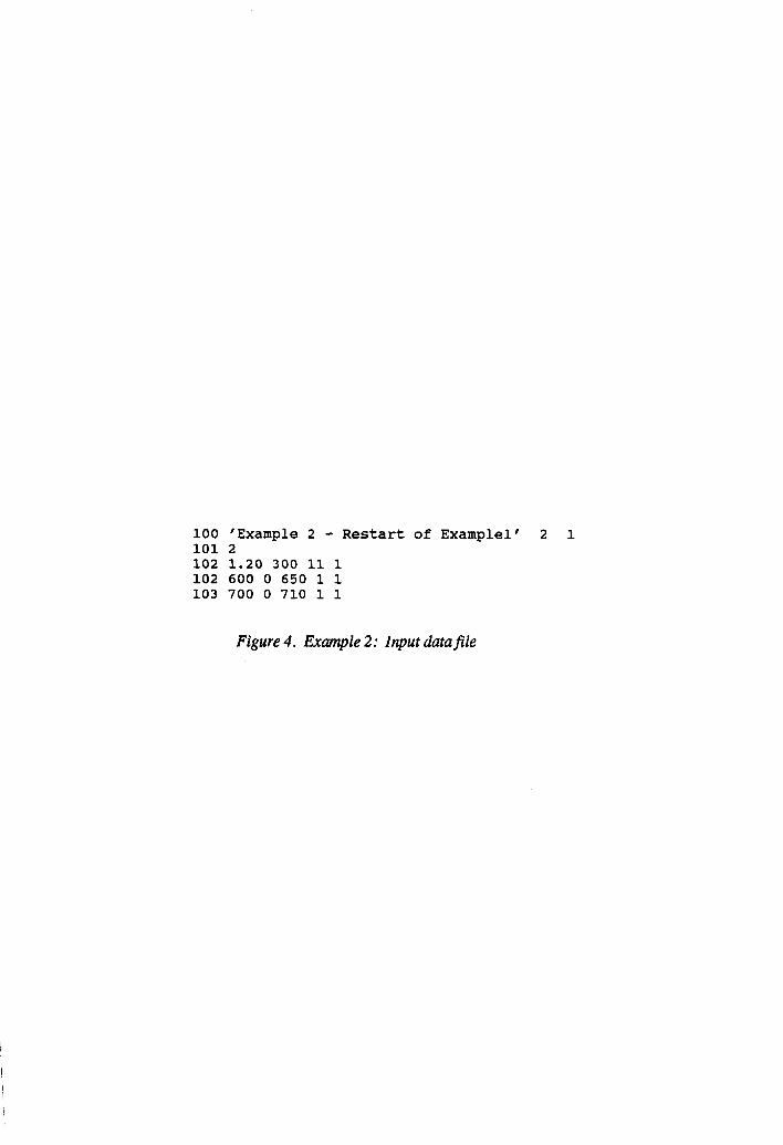
100 'Example 2 - Restart of Examplel' 2 1 101 2 102 1.20 300 11 1 102 600 0 650 1 1 103 700 0 710 1 1
Figure 4. Example 2: input data file

***********t**CURRENT CONDITIONS IN COMPRESSIBLE FOUNDATION*************
***:k* COORDINATES ***** ***** VOID RATIOS *****
A XI z EINITIAL E EFINAL MATERIAL 9.99 9.92 3.02 2.52 2.41 2.93 3 8.24 8.20 2.52 2.43 2.38 2.83 3 6.53 6.51 2.02 2.36 2.33 2.73 3 4.85 4.85 1.51 2.29 2.28 2.62 3 3.21 3.21 1.01 2.23 2.23 2.52 3 1.59 1.59 . 50 2.18 2.18
00 2.43 3
. . 00 . 00 2.13 2.13 2.36 3
**f** STRESSES *+*+* ***** PORE PRESSURES *****
XI TOTAL EFFECTIVE TOTAL STATIC EXCESS MATERIAL 9.92 310.00 72.27 237.74 195.14 42.60 3 8.20 474.37 101.47 372.89 301.96 70.94 3 6.51 637.44 139.89 497.56 407.48 90.07 3 4.85 798.98 182.14 616.85 511.48 105.37 3 3.21 958.91 234.48 724.43 613.86 110.58 3 1.59 1117.25 291.69 825.56 714.65 110.92 3
. 00 1274.07 345.28 928.79 813.92 114.86 3
TIME = 600.00 DEGREE OF CONSOLIDATION = -3921
SETTLEMENT = . 07 FINAL SETTLEMENT = . 19
BOTTOM BOUNDARY GRADIENT = . 09
Figure 5. Example 2: Output (Sheet 1 of4)

*******************CURRENT CONDITIONS IN DREDGED FILL*************+,*+**
***** COORDINATES ***** ***** VOID RATIOS *****
A XI Z EINITIAL E EFINAL MATERIAL 9.00 3.88 .68 8.30 3.10 3-10 2 8.25 3.63 63
:57 8.30 3.10 3.10 2
7.50 3.41 8.30 3.10 3.10 2 6.75 3.13 .51 8.30 4.81 4.81 2 6.00 2.77 .46 12.15 5.27 5-11 1 5.25 2.45 .40 12.15 4.57 5.04 1 4.50 2.11 . 34 12.15 5.22 4..98 1 3.75 1.76 . 29 12.15 5.21 4..94 1 3.00 1.40 .23 12.15 5.20 4..90 1 2.25 1.05 . 17 12.15 5.18 4..85 1 1.50 .70 . 11 12.15 5.15 4.81 1
.75 . 35 .06 12.15 5.11 4.76 1
.oo . 00 .oo 12.15 5.07 4.73 1
***** STRESSES **f** ***** PORE PRESSURES ****lt
XI 3.88 3.63 3.41 3.13 2.77 2.45 2.11 1.76 1.40 1.05
.70 . 35 . 00
TOTAL EFFECTIVE TOTAL STATIC EXCESS MATERIAL .oo . 00 . 00 . 00 I, 00 2
18.06 18.06 . 00 . 00 .I 00 2 36.12 36.12 . 00 . 00 s, 00 2 58.81 58.81 . 00 . 00 .I 00 2 86.73 55.33 31.40 22.22 9..17 1
112.42 70.20 42.22 42.22 00 16119
1 139.39 59.71 79.68 63.49 1 167.20 60.54 106.66 85.61 21.05 1 194.96 61.74 133.22 107.68 25-54 1 222.67 63.47 159.21 129.70 29.,51 1 250.30 65.79 184.50 151.63 32-88 1 277.82 68.74 209.07 173.45 35.,62 1 305.20 72.27 232.93 195.14 37.,79 1
TIME = 600.00 DEGREE OF CONSOLIDATION = .8791
SETTLEMENT = 5.12 FINAL SETTLEMENT = 4.44
SETTLEMENT DUE TO CONSOLIDATION = 3.91
SETTLEMENT DUE TO DESICCATION = 1.22
BOTTOM BOUNDARY GRADIENT = -24.24
SURFACE ELEVATION = 113.80
Figure 5. (Sheet 2 of 4)

**************CURRENT CONDITIONS IN COMPRESSIBLE FOUNDATION*************
***** COORDINATES ***** ***** VOID RATIOS *****
A 9.99 8.24 6.53 4.85 3.21 1.59
. 00
XI 9.90 8.19 6.51 4.84 3.21 1.59
. 00
XI Z EINITIAL E EFINAL MATERIAL 9.90 3.02 2.52 2.39 2.93 3 8.19 2.52 2.43 2.36 2.83 3 6.51 2.02 2.36 2.32 2.73 3 4.84 1.51 2.29 2.28 2.62 3 3.21 1.01 2.23 2.23 2.52 3 1.59 . 50 2.18 2.18 2.43 3
.oo . 00 2.13 2.13 2.36 3
***** STRESSES ***** ***** PORE PRESSURES *****
TOTAL EFFECTIVE TOTAL STATIC EXCESS MATERIAL 304.19 94.73 209.45 189.32 20.13 3 467.93 113.39 354.54 295.52 59.02 3 630.67 146.39 484.28 400.71 83.57 3 792.02 185.72 606.30 504.52 101.78 3 951.85 237.08 714.77 606.80 107.97 3
1110.14 292.78 817.36 707.54 109.82 3 1266.95 345.28 921.66 806.80 114.86 3
TIME = 700.00 DEGREE OF CONSOLIDATION = .5030
SETTLEMENT = .09 FINAL SETTLEMENT = . 19
BOTTOM BOUNDARY GRADIENT = .14
Figure5. (Sheet3of4)

!
*******************CURRENT CONDITIONS IN DREDGED FILL**+*****+*****+****
***** COORDINATES ***** ***** VOID RATIOS *****
A 9.00 8.25 7.50 6.75 6.00 5.25 4.50 3.75 3.00 2.25 1.50
.75
. 00
XI 3.79 3.54 3.32 3.03 2.69 2.36 2.03 1.69 1.35 1.01
. 67 .34 . 00
XI 2 EINITIAL E EFINAL MATERIAL 3.79 .68 8.30 3.10 3.10 2 3.54 . 63 8.30 3.10 3.10 2 3.32 .57 8.30 3.10 3.10 2 3.03 .51 8.30 4.81 4.81 2 2.69 .46 12.15 5.11 5.11 1 2.36 .40 12.15 4.57 5.04 1 2.03 . 34 12.15 4.98 4.98 1 1.69 .29 12.15 4.97 4.94 1 1.35 .23 12.15 4.96 4.90 1 1.01 .17 12.15 4.94 4.85 1
. 67 . 11 12.15 4.92 4.81 1
. 34 . 06 12.15 4.90 4.76 1
. 00 . 00 12.15 4.88 4.73 1
***** STRESSES **X*f ***** PORE PRESSURES *****
TOTAL EFFECTIVE TOTAL STATIC .oo . 00 . 00 . 00
18.06 18.06 . 00 . 00 36.12 36.12 . 00 . 00 58.81 58.81 . 00 . 00 86.22 64.50 21.72 21.72
111.95 70.20 41.76 41.76 138.40 75.89 62.51 62.51 165.37 82.24 83.13 83.78 192.30 83.92 108.38 105.01 219.17 85.91 133.26 126.20 245.99 88.34 157.64 147.32 272.73 91.28 181.45 168.36 299.38 94.73 204.65 189.32
EXCESS MATERIAL .oo 2 .oo 2 .oo 2
:oo 00 2 1 . 00 1
-:65 00 1 1 3.36 1 7.06 1
10.33 1 13.08 1 15.32 1
TIME = 700.00 DEGREE OF CONSOLIDATION =
SETTLEMENT = 5.21 FINAL SETTLEMENT =
SETTLEMENT DUE TO CONSOLIDATION = 3.99
SETTLEMENT DUE TO DESICCATION = 1.22
BOTTOM BOUNDARY GRADIENT = -35.73
SURFACE ELEVATION = 113.69
*** A CUMULATIVE MASS ERROR OF 4.51% WAS DETECTED. ***
Figure 5. (Sheet 4 of 4)
8989
4.44

9
10
11
13
14
15
Appendix A: Summary and Explanation of INPCDDF Error Messsages
The following is a complete listing of the run-time errors for the Interactive Data Input Program, INPCDDF, which accompanies PCDDF89. INPCDDF is coded in B.ASIC and was compiled using Borland’s TurboBasic compiler version 1.1. (Note that the error mes- sages are listed in numerical order; however, the error numbers are not sequential.)
Error Number Dewighn
Syntax error A run-time syntax error has been created by a BEAD statement trying to load string data into a numeric variable.
RETURN without GOSUB A RETURN was encountered without a matching GOSUB; that is, there is noth- ing to RETURN from.
Out of data A BEAD statement ran out of DATA statement values.
5 Illegal function call This is a catch-all error related to passing an inappropriate argument to some state- ment or function.
Overflow An overflow is the result of a calculation producing a value too large to be repre- sented in the indicated numeric type.
Out of memory Many different situations can cause this message, including dimensioning too large an array or passing many arrays to a subprocedure or function.
Subscript out of range User attempted to use a subscript larger than the maximum value established when the array was dimensioned.
Duplicate definition User attempted to dynamically dimension an array for the second time, without first erasing it.
Division by zero User attempted to divide by zero or to raise zero to a negative power.
Type mismatch User entered a string value where a numeric value was expected or vice versa. This can occur in PRINT USING, DRAW, or PLAY statements.
Out of string space String storage space is exhausted; string memory is limited to 64K.
String too long The string produced by a string expression is longer than 32,767 bytes.
Al
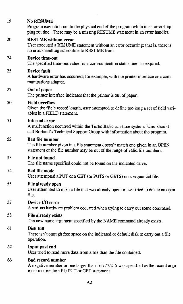
19
20
24
25
27
50
51
52
53
54
55
57
58
61
62
63
No RESUME Program execution ran to the physical end of the program while in an error-trap- ping routine. There may be a missing RESUME statement in an error handler.
RESUME without error User executed a RESUME statement without an error occurring; that is, there is no error-handling subroutine to RESUME from.
Device time-out The specified time-out value for a communication status line has expired.
Device fault A hardware error has occurred; for example, with the printer interface or a com- munications adapter.
Out of paper The printer interface indicates that the printer is out of paper.
Field overflow Given the file’s record length, user attempted to define too long a set of field vari- ables in a FIELD statement.
Internal error A malfunction occurred within the Turbo Basic run-time system. User should call Borland’s Technical Support Group with information about the program.
Bad file number The file number given in a file statement doesn’t match one given in an OPEN statement or the file number may be out of the range of valid file numbers.
File not found The file name specified could not be found on the indicated drive.
Bad file mode User attempted a PUT or a GET (or PUT$ or GET$) on a sequential file.
File already open User attempted to open a file that was already open or user tried to delete an open file.
Device I/O error A serious hardware problem occurred when trying to carry out some command.
File already exists The new name argument specified by the NAME command already exists.
Disk full There isn’t enough free space on the indicated or default disk to carry out a file operation.
Input past end User tried to read more data from a file than the file contained.
Bad record number A negative number or one larger than 16,777,215 was specified as the record argu- ment to a random file PUT or GET statement.
A2

64
67
68
69
70
71
72
74
75
76
201
202
203
204
Bad file name The file name specified in a FILES, KILL, or NAME statement contains invalid characters.
Too many files This error can be caused either by trying to create too many files in a drive’s root directory or by an invalid file name that affects the performance of DOS’s Create File system call.
Device unavailable User tried to OPEN a device file on a machine without that device; for example, COMl on a system without a serial adapter or modem.
Communications buffer overflow User executed a statement to INPUT characters into an already full communica- tions buffer. The program should either check and empty the buffer rnore often or provide a larger buffer size.
Permission denied User tried to write to a write-protected disk.
Disk not ready The door of a floppy disk drive is open or there is no disk in the indicated drive.
Disk media error The controller board of a floppy or hard disk indicates a hard media error in one or more sectors.
Rename across disks User cannot rename a file across disks.
Path/File access error During a command capable of specifying a path name (OPEN, RENAME, MKDIR, for example), user used a path inappropriately; for example, trying to OPEN a subdirectory or to delete an in-use directory.
Path not found User specified a path during CHDIR, MKDIR, OPEN, etc., which cannot be found.
Out of stack space User has run out of stack space.
Out of string temp space A string expression required the use of too many temporary string buffers.
Mismatched common variables User attempted to CHAIN between two program segments that did not contain matching COMMON statements.
Mismatched program options User attempted to CHAIN between two program segments that were compiled with different program options (different math library, math coprocessor required, and so forth).
A3

205
206
Mismatched program revisions User attempted to CHAIN between two program segments that were created with different versions of the Turbo Basic compiler.
Invalid program tile User attempted to CHAIN or RUN a program segment that was not compiled with Turbo Basic.
242 String/array memory corrupt The string memory area has been improperly overwritten. This could be caused by the improper action of an assembler subroutine, string array access outside of the dimensioned limits, or by an error within the Turbo Basic run-time system.
243 CHAIN/RUN from .EXE file only User attempted to CHAIN or RUN a program segment from within the Turbo Basic environment.
A4

APPENDIX B: INPCDDF INTERACTIVE INPUT SCREENS
The following is a complete listing of the interactive data input screens in INPCDDF.
PCDDF89 INTERACTIVE DATA PROGRAfl
By: Dr. Timothy D. Stark It Dr. Arsalan Ghahramani Department of Civil Engineering San Diego State University Version 1A
Enter letter for Desired Option:
N = To create a new data file E = To edit an existing data file C = To convert an old PCDDF data file to PCDDF87 format II = To create or edit a Restart data file
Figure Bl. Initial INPCDDF menu

WEU PCDDFB9 DATA FILE z
Name of Data File (e.g. C:PCDDFB9.DAT) B
Use Cursor Keys to Nove Through Nenu, Use Backspace Key to Edit Data Press Fl to Continue
Figure B2. Input screen for name of new PCDDF89 data fire
c tM INPCDDF IENU
ENTER INTEGER FOR DESIRED OPTION
1 = Create a New Data File or Edit Current Data File 2 - Prograr Execution Data 3 = Compressible Foundation ftaterial Properties 4 = Haterial Properties of First Dredged Fill Layer 5 = Incompressible Foundation Naterial Properties 6 = Execution Time Increment and Grid Size 1 z Print Times and New Dredged Fill Material Properties 8 - Desiccation Properties of Dredged Fill 9 - Evaporation and Precipitaion Data
10 = Final Dredged Fill Desiccation Parameters 11 = Save Data File and Remain in INPCDDF 12 - Save Data File and Exit to DOS 13 = Exit to DOS 14 - Restart Interactive Data Program 15 = Shell to DOS (Return by typing ‘Exit’ and Enter)
THE CURRENT DATAFILE BEING EDITED IS : T-D-Stark II
Figure B3. Main INPCDDF menu
B2

EXISTING PCDDP OR PCDDF89 DATA PILE
Name of Data Pile (e.g. C:PCDDP89.DAT) B
I Use Cursor Keys to Now Through Nenu, Use Backspace Key to Edit Data Press Fl to Continue u
Figure B4. Input screen for name of existing PCDDF89 data file
NEU PCDDP89 DATA PILE
Name of Data File (e.g. C:PCDDPB9,DfiTI
Figure BS. Input screen for name of new PCDDF89 data file
B3 / ’ ;
I
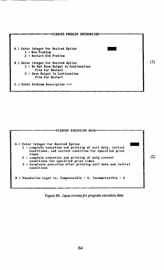
I=- PCDDFB9 PROBLEll INFORflf3TlON
A.1 Enter Integer for Desired Option 1 = Ntu Problem 2 = Restart Old Probler
B.1 Enter Integer for Desired Option 1 = Do Not Save Output in Continuation
File for Restart 2 = Save Output in Continuation
File for Restart
C.) Enter Problem Description ==>
II== PCDDFBV EXECUTION DfhT’=-~~
0.1 Enter Integer for Desired Option 1 = complete execution and printing of soil data, initial
conditions, and current condition for specified print times
2 = complete execution and printing of only current conditions for specified print times
3 = (erminate execution after printing soil data and initial I cond i t ions
B.) Foundation Layer is, Compressible = 1, Incompressible = 2
(2)
Figure B6. Input screens for program execution data
B4

WHBER OF COHPRESSIBLE FOUNDATION LAYERS
Number of Compressible Foundation Layers m
(1)
- No. OF COHPRESSlBLE FOUNDIITION LMERS = 1, ntlTERI(IL ID. OF LfiYER No. 1.
tktterial ldentif ication Number of Compressible Foundation Layer m
2 BASE LAYERS, THICKNESS OF LAYER NO.
Initial Thickness of Compressible Foundation
2 -
(3)
Figure B7. Input screens 1 through 3 for compressible foundation layers
B5

ctlATERML PROPERTIES OF COHPRESSIRLE FOUNDATION LIIYER NO. 1, MTERIAL ID,
Splecif ic Gravity of Compressible Foundat ion Layer
Initial Thickness of Compressible Foundation layer
No. of Data Points used to define Void Ratio, Permeability and Effective Stress Relationships
< SOURCE OF INPUT DATA FOR HATERIAL ID. 8
Enter Integer for Desired I Option
8 = Input data interactively or display current material properties 1 = load data from existing datafile only 2 = Load data from existing datafile and edit data
PROPERTIES OF rV1TERlnL ID. e Void Effectlm Void Effective Aat lo stress Ratio stress
1I Perreablllty Psrmeabilit!
16 2 17 3 4 5 6 7
i 19 11 12
:: 15
26
fli 29 39
Use Backspace Key to Edit Data Ptvrso Fl to Save Current Edit and Advance to Next Menu Press FZ to Save Current Edit and Return to IlaIn flcuu
(4A)
(5)
Figure B8. Input screens 4 through 5 for compressible foundation layers
B6

EXISTING DATA FILE FOR DREDGED FILL H6TERIAL ID. 0 ==
Name of Existing Data File (e.g. C:PCDDF89.DAT) -
I-
Use Cursor Keys to Hove Through Henu, Use Backspace Key to Edit Data Press Fl to Save Current Edit and Advance to Next Henu Press F2 to Save Current Edit and Return to Hain Menu Press F3 to Undo Edit on Current Screen
I
Figure B9. Input screens for name of data file containing the compressible foundation material properties

-- MTERIAL PROPERTIES OF FIRST DREDGED FILL LfiYER *
Specific Gravity of Dredged Fill
Initial Thickness of Dredged Fill
Initial Void Ratio of Dredged Fill
Unit Ueight of Uater
No. of data points used to define Soil Relationships
Material Identification No. of First Dredged Fill Layer
(1)
==SOURCE OF INPUT DATA FOR DREDGED FILL tlATERIAL ID. 8 ’
Enter Integer for Desired Option
Q= Input data interactively or display current material properties 1 = Load data from existing datafile only 2 = Load data from existing datafile and edit data (1~9
I 1 1 1
: 1
C
-- SOIL PROPERTIES OF DREDGED FILL WTERIIIL ID. 8 Void Effective Vald Effective Rat lo stress Permeability Rat la stress Permeabillt!
16 17
Use Cursor Keys ta Move Through Menu, Use Backspace Key to Edit Data Press Pl to Save Current Edit and edvance to Next Menu Press F2 to Save Current Edit and Return to tlaln Menu Press P3 to Undo Edit on Current Screen
(2)
Figure BIO. Input screens for first dredgedfill layer
B8

-TERM, PROPERTIES OF INCOM’RESSIBlJ FOUWD1\TION LAYER==
titerial Properties at the top of the lncoMpressib\e Foundation
Permeabi l i ty
length of Drainage Path in Incompressible Foundation
Elevation at Top of Incompressible Foundation
Elevation of Water Table in Foundation
Figure Bl I. Input screen for incompressible foundation layer
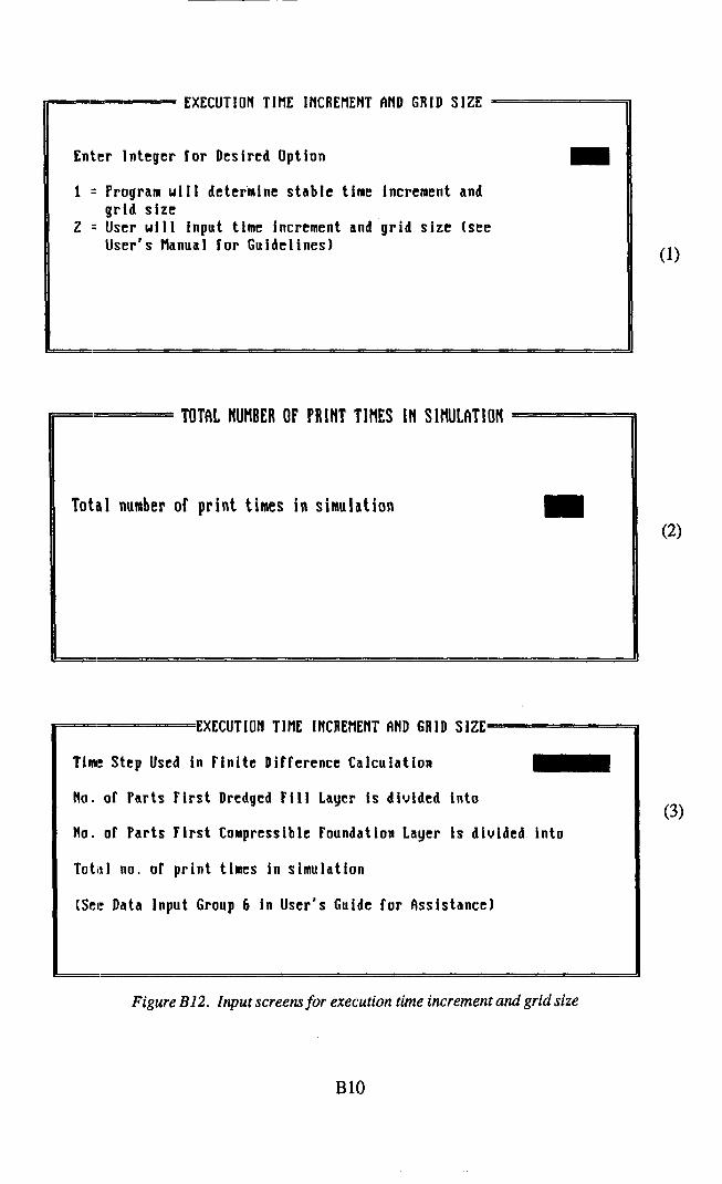
- EXECUTION TltlE IflCREtlENT AND GRID SIZE -
Enter Integer for Desired Option
1 = Program uill determine stable time increment and grid size
2 = User will input time increment and grid size (see User's Hanual for Guidelines) (1)
F:
Z TOThI NMBER OF PRINT TlflES IN Slf4JL~TION
Total number of print times in simulation
EXECUTION TIllE INCREtlENT fiND GRID SIZE
Tinrt Step Used in Finite Difference Calculation
No. of Parts First Dredged Fill Layer is divided into
No. of Parts Pirst Compressible Foundation Layer is divided into
Total no. of print times in simulation
(Sel! Data input Group 6 in User's Guide for hsistance)
Figure Bl2. Input screens for execution time increment and grid size
BlO
(3)

DREDCCD PILL DfiTA AT ?RINT TIME NO. oar 8
Time Pcrlods (days) after l ddltlon or First Dredged Plll Layer m
Inltlal Thickness of Ncu Dredged Fill (If greater than zero propcrtlcs or Dredged rlll ulll be raqulrcd)
of Time Periods after l ddltlon of Plrst Dredged Pill Layer .t which Dcslccatlon starts In the New Dredged Pll Layer
“obnth “,,. at uhlch Derlccstlon starts In Neu PI11 (January = 1)
Enter Integer Tar Desired Print Optlon 1 1 = Print current uold ratLo. errectle stress and pore
~F~SSUFC pr0r 1 ICS
Use Cursor Wcus to Hove Throuah Bcnu. USC BacksDeco Kcu to Edlt Data Press Fl to S;ve Current Ldlt-and Advance to Ma;t Honu- Press FZ to Save Curreut Edit and Return, to )hln %zwu II
11 Press F3 to Undo Edlt on Current Screen I
lDENTlFICATlOli Ho. OF NEU DREDGED FILL LAYER No. 2 =
flaterial ldent if ication Number of Neu Dredged Fill layer m
INlTIhL VOID RATIO OF DREDGED FILL NO. 2 -
Initial Uoid Ratio of Dredged Fill
(2)
(3)
Figure B13. Input screens I through 3 for print times and new dredgedfill data
Bll

SOIL PROPERTIES OF DREDGED PILL LRYER No. 2
Specific Gravity of Dredged Fill
Initial Uoid Ratio of Dredged Fill
No. of Data Points used to define Void Ratio, Permeability, and Erfective Stress Relationships
-0URCE OF INPUT DATA FOR HATERIAL ID. 1
Enter Integer for Desired Option
8 = Input data interactively or d 1 = Load data from existing dataf 2 = Load data from existing dataf
splay current material properties Ic only lc and edit data
rROPERTIES OP I'MTERIfiL ID. 1 Void crrcct lw3 Void Eftccttve Rat IO stress Pcrllcablllty Rat lo stress Pcrrrcabl I ItI
1- 16 2 17 3
:3 fi 15 30
Use Curtor Keys to tlovc Through tlecnu, Use Backspace Key to Edit Data Press Fl to Save Current Edlt and fidvsnce to Next rlcnu Press PP. to Smve Current tdlt and Return to Haln Hen,, Press i3 to Undo Edit an Current Screen 1
- Figure B14. Input screens 4 through 5 for print times and new dredged
fill data
(4)
Y
I (4A)
(5)
B12

> DREDGED FILL DESICCATION DATA Desiccation Limit
Shrinkage Limit
no. of Time Periods (days) per month
Surface Drainage Efficiency (well drained = 11
No. of Time Periods (days) to start of Desiccation in First Dredged Fill Layer
Month No. at which Desiccation starts for this print time (Jan.=11
Enter Integer for Desired Print Option 1 = Print current void ratio, effective stress and
pore pressure profiles 2 = Print only current void ratio profile 3 = Do not print any current profile
Use Cursor Keys to tiove Through Menu, Use Backspace Key to Edit Data Press Fl to Save Current Edit and Advance to Next Menu Press F2 to Save Current Edit and Return to Hain Menu Press F3 to Undo Edit on Current Screen
Figure B15. Input screen for dredgedfill desiccation data
B13
-

RECIPIT~TION AND RAINM,L SOURCE UP DATR
Enter Integer for Desired Option
Input data interactively or display current material properties 1 = Load data frora existing datafile only 2 = load data from existing datafilc and edit data
EXISTING PRECIPIT~TlOfl r\ND IMINFALL DATA FILE
Name of Existing Data File (e.g. C:PCDDFl39.Df+T) ~-
NNUfiL EW\PURI\TIUN MD PRECIPlTRTlU~ DITfl
Class A Pan Evaporation Potential dur lng I - Rainfal I Expected
during
January February tlarch (Ipril
flay June July fiugurt September
I
October November December
Figure Bl6. Input screens for evaporation and precipitation data
B14

FlUI DREDGED FILL DESICCElTlOH PARAlIETERS
Haxinur Dredged Ml Evaporation Efficiency for Desiccation m
Degree of Saturation (decimals) of Dredged Fill at Desiccation linit
Haxiraum Depth to which Second-Stage Drying uill occur
Figure B17. Input screen for final dredged fill desiccation parpmeters
INPCDDF RESTART OPTION
Enter Letter for Desired Option:
N q To create a new RESTART data file E - To edit an existing RESTART data file
Figure Bl8. Initial INPCDDF restart menu
B15

MEW RESTART DATA FILE
Name of Data File (e.g. C:PCDDF89.DATl B
Use Cursor Keys to Howe Through Menu, Use Backspace Key to Edit Data Press Fl to Continue
Figure B19. Input screen for name of new PCDDF89 restart data file
PREVIOUSLY SAVED CONTINUATIOfl FILE FOR RESTART
Name of Data File (e.g. C:PCDDF89,DAT) B
Use Cursor Keys to Howe Through Henu, Use Backspace Key to Edit Data Press Fl to Continue
Figure B20. Input screen for name of previously saved continuation file
B16

MN INPCDDF RESTART HENU
ENTER INTEGER FOR DESIRED OPTION 1
1 = Create New Restart Data file or Edit Current Data file 2 = Program Execution Data 3 : Print Times and Dredged fill Data from last Simulation 4 = Print Times and New Dredged fill layer Data S = Save Data File and Remain in INPCDDT 6 z Save Data file and Exit to DOS 7 = Exit to DOS 8 = Restart Interactive Data Program 7 = Shell to DOS (Return by typing ‘Exit’ and Enter)
THE CURRENT DMfiflLE BEING EDITED IS : T-D-Stark
Figure B21. Main INPCDDF restart menu
EXISTIHG RESTART DATA FILE
Name of Data Pile (e.g. C:PCDDPB9.DATI I-
Use Cursor Keys to tloue Through Menu, Use Backspace Key to Edit Data Press Pl to Continue
Figure B22. Input screen for name of existing PCDDF89 restart data file
B17

q PREVIOUSLY SAVED CONTINUATION FILE FOR RESTART
Name of Data File (e.g. C:PCDDF89.DAT) B
Use Cursor Keys to Moue Through Menu, Use Backspace Key to Edit Data Press Fl to Continue
Figure B23. Input screen for name of previously saved continuationple
NEW RESTART DATA FILE
Name of Data File (e.g. C:PCDDF89.DAT) I-
Use Cursor Keys to Move Through lenu, Use Backspace Key to Edit Data Press Fl to Continue
Figure B24. Input screen for name of new PCDDF89 data file
B18

CDDFl39 PRlJBLEtl INFORHfITlOIl
fl.1 Enter Integer for Desired Option = Mew Problem = Restart Old Problem
6.1 Enter Integer for Desired Option 1 = Do not Save Output in Continuation
File for Restart 2 = Save Output in Continuation
File for Restart
C.) Enter Problem Description ==>
NEW RESTART PRINT TIMES -
Number of Restart Print Times
Number of Print Times Detected in Continuation File
(Total Number of Print Times for Initial Execution and Restart is the SUM of the above)
Figure B25. Restart input screens for program execution data
B19

Ii= = DREDGED FILL DATA FROH MST LAYER OF PREVIOUS SIMULATIOti
Initial Thickness of last Dredged Fill layer Placed
No. of Time periods after addition of First Dlredged FiI 1 layer at which Desiccation started
Plonth number at which Desiccation started (January = 11
Integer for Desired Print Option 1 = Print current void ratio, effective stress and pore
pressure prof i Ies 2 = Print only current void ratio profile 3 = Do not print any current profile
Figure B26. Restart input screen for dredged fill data from previous simulation
B20

DREDGED FILL DATf# AT PRINT TIRE NO. SOF 6
Time Perladr (days) after l ddltlon of First Dredged fill Layer F
Inltlrl Thickness ot Wcr Dredged rlll Clr greater than LC~VI propartlss or Dredged Fill VIII be rcqulrad>
no. of Time Parlods after l ddltlon or Flrtt Dredged SIII Layer at uhlch Darlccatlon starts In the New Dredged rll Layer
P&math Ilo. at uhlch Dolccmtlon starts In Neu fill CJanurry = 1)
Enter Integer (or Dcrlrsd lrlnt Optlon
1 = Print current wld ratlo. errccti- stress l nd par- PP~SSUF~ pr0riict
2 = hint only current v01d ratio prorile 3 = Do not print any current pr0riic
- Use Cursor Keys to Hove Through Menu. Use Backspace Key to Edit Data Press Fl to Ssuc Current Ldlt and Advance to Next Menu Press TZ to Save Currant Edlt and Return to tlaln t%znu Press F3 to Undo Edlt on Current Screen
IDENTIFICfiTlOH No. OF NEW DREDGED FILL LfiYER No. 2
Material Identification Number of Ncu Dredged Fill Layer
INITIAL VOID RATIO OF DREDGED FILL NO. 2
Initial Void Ratio of Dredged Fill
.
(1)
(2)
(3)
Figure B27. Restart input screens 1 through 3 for print times and new dredgedfill layer data
B21

SOIL ?ROPERTtES OF DREDGED PILL LfWER No. 2
Specific Gravity of Dredged Fill
Initial Void Ratio of Dredged Pill
No. of Data Points used to dcl'ine Void Ratio, Perncabillty, and Effectlvc Stress Rclationshlps
-0URCE OF INPUT DATR FOR tlflTERIA1 ID. 8
Enter Integer for Desired Option
8 = Input data interactively or display current material properties 1 = load data from existing dataTile only 2 = load data from existing datarile and cdlt data
PROPERTIES OP WTLRII)L ID. 8 Uold EfCcctlve nrt lo stress Perreabllltf
Void cfrectlve Rat lo stress
:-
Permenblllty 16 17 18 19
5: 22
f: 2s 26
f;: 23 30
14 1s
Use Cursor Weys to lloue Through Menu. Use Backspace Key to Edit Data Press Fl to Sauc Current Edlt and Advance to Next tlcnu Press P2 to Saw Current Edlt end Return to Haln Henu Press F3 to Undo Cdlt on Current Screen
(4A)
(5)
Figure B28. Restart input screens 4 through 5 for print times and new dredgedjill layer data
B22

EXISTING DATA FILE FOR IIATERIAL ID. 8
Name of Existing Data File (e.g. C:PCDDFBS.DAT) mm
Use Cursor Keys to tloue Through llenu, Use Backspace Key to Edit Data Press Fl to Save Current Edit and Advance to Next tlenu Press F2 to Save Current Edit and Return to lain Menu Press F3 to Undo Edit on Current Screen
-
Figure B29. Input screen for name of data file containing dredged fill material properties
B23