Embed Size (px)
Citation preview
GAUTENG DEPARTMENT OF INFRUSTRUCTURE
DEVELOPMENT
BUILDING ASSESSMENT REPORT
HVAC
FOR
78 FOX STREET
OCTOBER 2014 – REV0

Report for Gauteng Department of Infrastructure Development HVAC Services Preliminary Report:78 Fox Street – Rev 0 October 2014
i | P a g e
Table of Contents
1. INTRODUCTION .......................................................................................................................... 1
1.1 Design Criteria and Specifications .............................................................................................. 1
1.2 Scope of the Services Scheme Report ........................................................................................ 1
2. PROJECT SUMMARY .................................................................................................................. 2
3. INSPECTION ............................................................................................................................... 2
3.1 System Description .................................................................................................................... 2
3.2 Chillers ........................................................................................................................................ 2
3.3 Cooling Towers ........................................................................................................................... 4
3.4 Chilled Water, Condenser Water Pumps ................................................................................... 5
3.5 Chilled Water Reticulation ......................................................................................................... 5
3.6 Condenser Water Reticulation ................................................................................................... 6
3.7 Fan Systems ................................................................................................................................ 6
3.8 Air Distribution ........................................................................................................................... 9
3.9 Toilet Ventilation ...................................................................................................................... 10
3.10 Basement Ventilation ............................................................................................................... 11
4 RECOMMENDATIONS ............................................................................................................... 13
4.1 HVAC ........................................................................................................................................ 13
1. INTRODUCTION
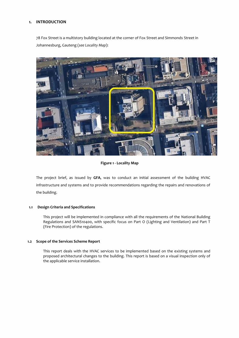
78 Fox Street is a multistory building located at the corner of Fox Street and Simmonds Street in
Johannesburg, Gauteng (see Locality Map):
Figure 1 - Locality Map
The project brief, as issued by GFA, was to conduct an initial assessment of the building HVAC
infrastructure and systems and to provide recommendations regarding the repairs and renovations of
the building.
1.1 Design Criteria and Specifications
This project will be implemented in compliance with all the requirements of the National Building Regulations and SANS10400, with specific focus on Part O (Lighting and Ventilation) and Part T (Fire Protection) of the regulations.
1.2 Scope of the Services Scheme Report
This report deals with the HVAC services to be implemented based on the existing systems and proposed architectural changes to the building. This report is based on a visual inspection only of the applicable service installation.

2. PROJECT SUMMARY
2.1 Project Description
78 Fox Street is a multi-storey building located at the corner of Fox and Simmonds Streets in Johannesburg, Gauteng. The building is currently in a state of disrepair and appears to have been in the process of being refurbished.
A significant amount of the existing equipment had either been vandalised or stripped of all components of value.
3. INSPECTION
This report is based on a visual inspection only of the applicable service installation.
3.1 System Description
78 Fox Street was conditioned by a 4-pipe chilled water system, incorporating what appears to be chilled water storage as well as hot water storage – these tanks are located in basement level 4. No chillers were found on site and it appears that they have been removed from the three mechanical plant levels. Chilled water and hot water were fed to the six mechanical plant room floors (between 9th and 10th floors, 18th and 19th floors and above the 27th floor). The chilled and hot water piping was distributed throughout the building in insulated steel chilled water and hot water risers in mechanical service shafts. Air was distributed to the spaces via six custom-built air handling plants on the mechanical plant floors (two air handling units each on the three mechanical plant floors). Air was supplied to the spaces through ceiling mounted diffusers. Air was returned to the plant levels through the ceiling voids and mechanical service shafts used as return air plenums. It was noted that there was ducting installed in a cavity in the perimeter walls, presumably connected to either chilled water induction or console units.
The chillers were cooled by eighteen Sulzer open circuit cooling towers located on the fourth tower level. Condenser water was reticulated between the chillers and cooling towers via uninsulated steel risers in the mechanical service shafts.
Fresh air was to be fed into each air-handling plant at plant level by dedicated fresh air fans.
The ablutions were mechanically ventilated with riser ducts and a common toilet extract fans located at the fourth tower level.
The basement parking areas were mechanically ventilated.
3.2 Chillers
No chillers were found during the inspection – they appear to have been removed recently. The chillers were water cooled (evident by condenser water piping found between the three mechanical plant levels and cooling towers).
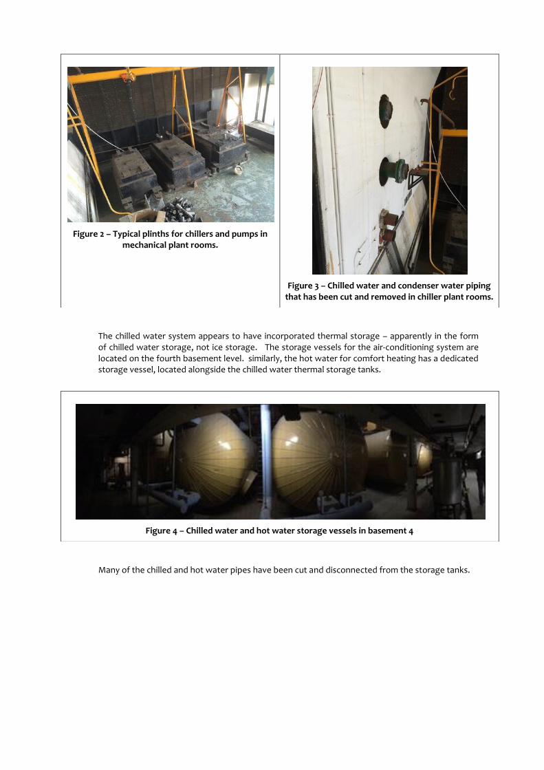
The chilled water system appears to have incorporated thermal storage – apparently in the form of chilled water storage, not ice storage. The storage vessels for the air-conditioning system are located on the fourth basement level. similarly, the hot water for comfort heating has a dedicated storage vessel, located alongside the chilled water thermal storage tanks.
Many of the chilled and hot water pipes have been cut and disconnected from the storage tanks.
Figure 2 – Typical plinths for chillers and pumps in mechanical plant rooms.
Figure 3 – Chilled water and condenser water piping that has been cut and removed in chiller plant rooms.
Figure 4 – Chilled water and hot water storage vessels in basement 4
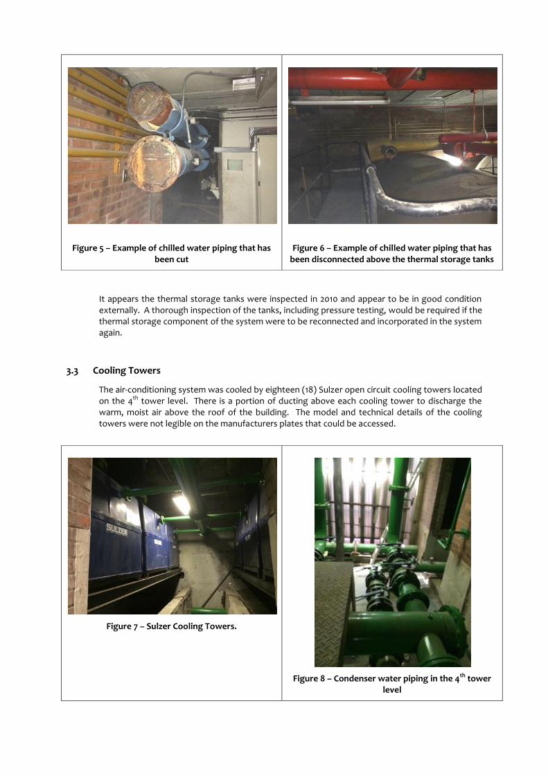
It appears the thermal storage tanks were inspected in 2010 and appear to be in good condition externally. A thorough inspection of the tanks, including pressure testing, would be required if the thermal storage component of the system were to be reconnected and incorporated in the system again.
3.3 Cooling Towers
The air-conditioning system was cooled by eighteen (18) Sulzer open circuit cooling towers located on the 4th tower level. There is a portion of ducting above each cooling tower to discharge the warm, moist air above the roof of the building. The model and technical details of the cooling towers were not legible on the manufacturers plates that could be accessed.
Figure 5 – Example of chilled water piping that has been cut
Figure 6 – Example of chilled water piping that has been disconnected above the thermal storage tanks
Figure 7 – Sulzer Cooling Towers.
Figure 8 – Condenser water piping in the 4th tower level
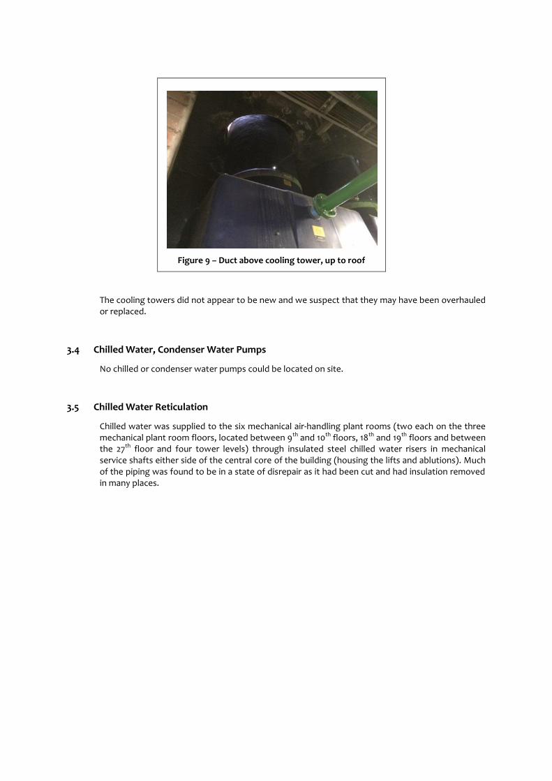
Figure 9 – Duct above cooling tower, up to roof
The cooling towers did not appear to be new and we suspect that they may have been overhauled or replaced.
3.4 Chilled Water, Condenser Water Pumps
No chilled or condenser water pumps could be located on site.
3.5 Chilled Water Reticulation
Chilled water was supplied to the six mechanical air-handling plant rooms (two each on the three mechanical plant room floors, located between 9th and 10th floors, 18th and 19th floors and between the 27th floor and four tower levels) through insulated steel chilled water risers in mechanical service shafts either side of the central core of the building (housing the lifts and ablutions). Much of the piping was found to be in a state of disrepair as it had been cut and had insulation removed in many places.
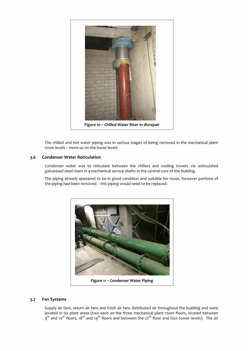
Figure 10 – Chilled Water Riser in disrepair
The chilled and hot water piping was in various stages of being removed in the mechanical plant room levels – more-so on the lower levels
3.6 Condenser Water Reticulation
Condenser water was to reticulate between the chillers and cooling towers via uninsulated galvanised steel risers in a mechanical service shafts in the central core of the building.
The piping already appeared to be in good condition and suitable for reuse, however portions of the piping had been removed – this piping would need to be replaced.
Figure 11 – Condenser Water Piping
3.7 Fan Systems
Supply air fans, return air fans and fresh air fans distributed air throughout the building and were located in six plant areas (two each on the three mechanical plant room floors, located between 9th and 10th floors, 18th and 19th floors and between the 27th floor and four tower levels). The air

handling units are in various states of disrepair, with many of the units on the lower levels having fan motors and / or fans themselves missing.
Many of the axial fans installed as part of the return air systems, lift pressurisation and staircase pressurisation fans were installed but the flexible couplings to the ducting systems were missing.
The filters for all of the air handling units will need to be replaced. The chilled and hot water coils will likely need to be replaced. The spray chambers, systems and associated piping would need to be replaced in order to have operation reinstated.
Figure 12 – Disconnected axial fan
Figure 13 – AHU Fan plenum with complete fan assembly
Figure 14 – Return Air Plenums
Figure 15 – AHU with incomplete fan assembly, typical of most of the AHUs

Given the plant room configuration and ducting arrangement we suspect the fan arrangement to be as follows:
FAN LOCATION AREA SUPPLIED
Supply Air Fan 1 3rd Mechanical level, West 27th floor down to 19th floor, west side
Supply Air Fan 1 3rd Mechanical level, east 27th floor down to 19th floor, east side
Supply Air Fan 1 2nd Mechanical level, West 18th floor down to 10th floor, west side
Supply Air Fan 1 2nd Mechanical level, east 18th floor down to 10th floor, east side
Supply Air Fan 1 1st Mechanical level, West 9th floor down to 1st floor, west side
Supply Air Fan 1 1st Mechanical level, east 9th floor down to 1st floor, east side
Return Air Fan 1 3rd Mechanical level, West 27th floor down to 19th floor, west side
Return Air Fan 1 3rd Mechanical level, east 27th floor down to 19th floor, east side
Return Air Fan 1 2nd Mechanical level, West 18th floor down to 10th floor, west side
Return Air Fan 1 2nd Mechanical level, east 18th floor down to 10th floor, east side
Return Air Fan 1 1st Mechanical level, West 9th floor down to 1st floor, west side
Return Air Fan 1 1st Mechanical level, east 9th floor down to 1st floor, east side
Lift / Staircase pressurisation Air Fan 1
3rd Mechanical level, West 27th floor down to 19th floor, west side
Lift / Staircase pressurisation Air Fan 1
3rd Mechanical level, east 27th floor down to 19th floor, east side
Lift / Staircase pressurisation Air Fan 1
2nd Mechanical level, West 18th floor down to 10th floor, west side
Lift / Staircase pressurisation Air Fan 1
2nd Mechanical level, east 18th floor down to 10th floor, east side
Lift / Staircase pressurisation Air Fan 1
1st Mechanical level, West 9th floor down to 1st floor, west side
Lift / Staircase pressurisation Air Fan 1
1st Mechanical level, east 9th floor down to 1st floor, east side
Table 1 – Supply Air Fan Configuration

As many of the fans are missing or are in a state of disrepair, we would recommend that the fans are replaced as follows:
Supply Air Fans: 6 off.
Return Air Fans: 6 off, although three of these fans appear to have been recently replaced).
Fresh Air Fans: 6 off.
Lift and Staircase Pressurisation fans: 12 off
3.8 Air Distribution
Air was supplied to the various floors and zones as per Table 1 via externally insulated galvanised steel ducting. The main duct risers and droppers were located in four mechanical riser shafts, one at each corner of the office areas. The risers and droppers appeared to be mostly installed and intact. A number of modifications were noted to the ducting, especially with branch ducts being blanked off. No fire dampers were noted between floors and the service shafts around the ducts were open between floors. Branch ducting is reticulated in the ceiling void, through sleeves provided in the structure / downstand beams. Many of these ducts have also been blanked off.
Additional branch ducting is also reticulated in a cavity around the building envelope, at low level.
This ducting presumably connected to chilled water consoles or induction units installed on the
perimeter although none were noted on site as some refurbishment had commenced and much of
the existing HVAC equipment had been removed.
Furthermore, installation of chilled water cassettes had started on the lower levels, but no pipe
reticulation was noted to any of these units.
Figure 16 – Duct riser showing blanked off branch duct, no fire damper and open cavity between floors.
Figure 17 – Branch Ducts in ceiling void, running through sleeves in beams

The existing floors were served by ceiling mounted diffusers of unknown manufacture.
Figure 20 – Ceiling Mounted Diffusers
3.9 Toilet Ventilation
The ablutions were mechanically ventilated. Branch ducts extracted air from each of the ablutions and fed into riser ducts. It appears that the toilet extract is split into three systems each for the male and female toilets, presumably one system each serving the floors between mechanical plant levels. Six axial fans are located on tower level 4.
The installation of fire dampers to each branch could not be established
The toilet extract fans currently discharge within the 4th tower level plant area. These systems should be ducted outside of the building (SANS10400 requirement).
Figure 18 – Branch duct (and piping) reticulating in cavity around building envelope perimeter.
Figure 19 – ceiling mounted cassette installed between downstand beams

3.10 Basement Ventilation
The parking basement is mechanically ventilated. The first basement ventilation system is a ducted system. The lower basement levels (Basements 2, 3 and 4) are ventilated by means of grilles mounted in a cavity wall around the perimeter, connected to a common shaft extracting to ground floor.
The fan assemblies and ducting extracting from the lower basement levels require reconfiguration to ensure correct operation. It is apparent that over the years changes have been made to the system that may have detrimentally affected system performance.
Figure 21 – Toilet Extract Fans
Figure 22 – Toilet Extract Ducting
Figure 23 –Cavity / duct for basement ventilation to lower levels
Figure 24 –High and low level grilles into cavity behind wall on lower levels

The electrical plant areas in the basements were ventilated, albeit the systems were not operational.
A ventilation system was noted in the thermal storage area of basement 4 – but it was not operational.
Figure 25 –Ducted system to upper basement level
Figure 26 –Upper basement ventilation system fan is in good condition

4 RECOMMENDATIONS
The remedial work required to meet the minimum national standard and reinstate the HVAC systems is
recommended and a high level budgetary cost for the remedial work is presented.
4.1 HVAC
1. Install new water-cooled chillers.
2. Install new chilled water system, including pumps, all reticulation, valves and cooling coils.
3. Replace cooling towers, including drift eliminators, reticulation, valves and controls.
4. Refurbish condenser water piping, adding in portions that have been removed.
5. Refurbish plant room areas and make good all openings to accommodate new filter banks,
louvers, dampers.
6. Install all main plant filters and filter banks, cooling coils and valves with reticulation.
7. Install new supply air, return air, fresh air and toilet extract fans.
8. Complete the ducting installation.
9. Supply and install fire dampers to HVAC ducts where required.
10. Install new ducting diffusers and grilles. Continue with installation of chilled water terminal units
where required.
11. Complete toilet extract system in compliance with SANS 10400:O and ensure correct balance
between fresh and extracted air. Extracted air to be discharged to atmosphere, not an enclosed
space
12. Refurbish the basement ventilation system in compliance with SANS 10400:O and Rational Fire
Design to unventilated areas. Repair existing fans and ducting where required.


![ANNEXURE S PROVINCIAL ADMINISTRATION: GAUTENG · PDF fileANNEXURE S PROVINCIAL ADMINISTRATION: GAUTENG DEPARTMENT OF EDUCATION ... [GN]: Physical Address ... Plan Implementation Report](https://img.pdfslide.net/doc/110x75/5a87c1387f8b9a001c8e09d9/annexure-s-provincial-administration-gauteng-s-provincial-administration-gauteng.jpg)