Embed Size (px)
Citation preview
REPORT FOR NASA-JSC CONTRACT
NAS9-7644
CASE FSLC
EXTRAVEHICULAR MOBILITY UNIT
THERMAL SIMULATOR FOR "0" MISSION
REPORT NO. Tl55-04
31 July 1973
SUBMITTED BY
VOUGHT SYSTEMS DIVISIONLTV AEROSPACE CORPORATION
P. 0. BOX 5907 - DALLAS, TEXAS - 75222
TO
NATIONAL AERONAUTICS AND SPACE ADMINISTRATIONJOHNSON SPACE CENTER - HOUSTON, TEXAS
https://ntrs.nasa.gov/search.jsp?R=19730021487 2018-07-16T03:03:27+00:00Z

REPORT FOR NASA-JSC CONTRACT
NAS9-7644
EXTRAVEHICULAR MOBILITY UNIT
THERMAL SIMULATOR FOR "J" MISSION
REPORT NO. Tl55-04
31 July 1973
SUBMITTED BY
VOUGHT SYSTEMS DIVISIONLTV AEROSPACE CORPORATION
P. 0. BOX 5907 - DALLAS, TEXAS - 75222
TO
NATIONAL AERONAUTICS AND SPACE ADMINISTRATIONJOHNSON SPACE CENTER - HOUSTON, TEXAS
Prepared by: Approved by:
g.Cu.C. W. Hixon R. JT French, Supervisor
EC/LS Group
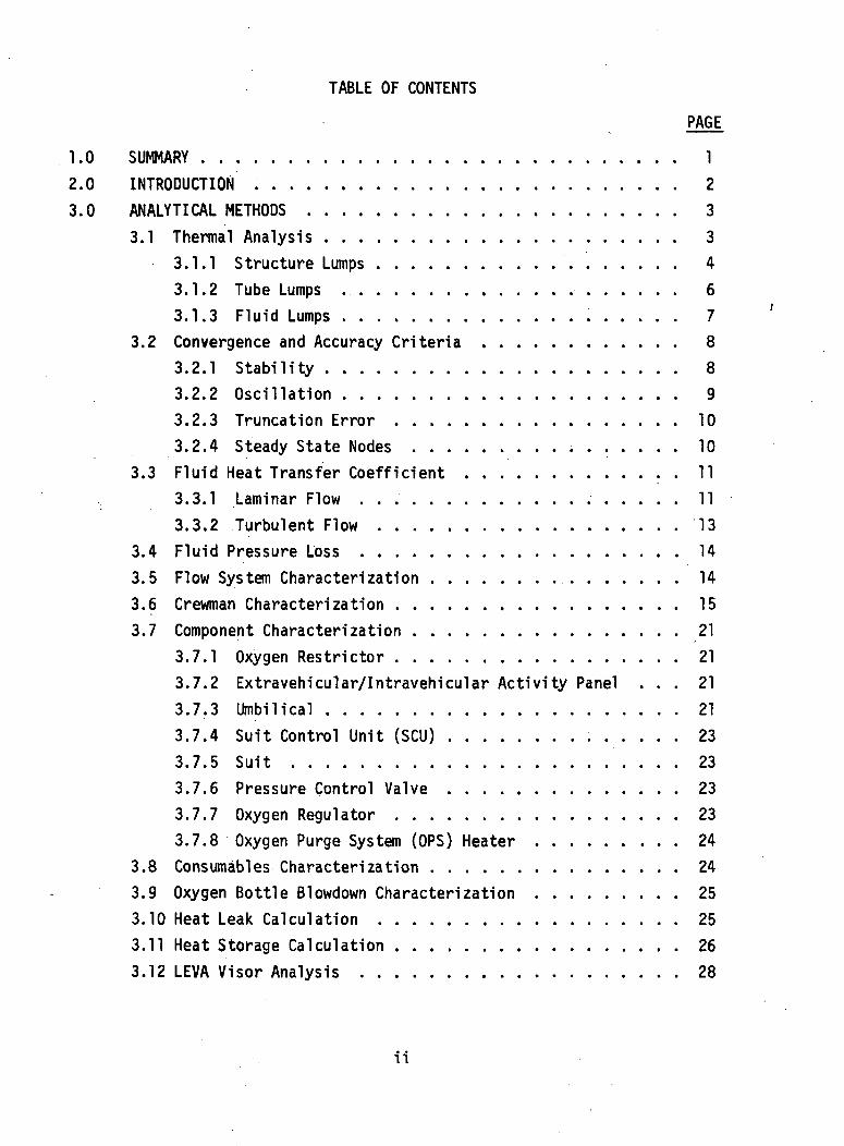
TABLE OF CONTENTS
PAGE
1.0 SUMMARY 1
2.0 INTRODUCTION 23.0 ANALYTICAL METHODS 3
3.1 Thermal Analysis 33.1.1 Structure Lumps 43.1.2 Tube Lumps 63.1.3 Fluid Lumps 7
3.2 Convergence and Accuracy Criteria . 83.2.1 Stability 83.2.2 Oscillation 93.2.3 Truncation Error 103.2.4 Steady State Nodes 10
3.3 Fluid Heat Transfer Coefficient 113.3.1 Laminar Flow 113.3.2 Turbulent Flow 13
3.4 Fluid Pressure Loss 143.5 Flow System Characterization 143.6 Crewman Characterization 153.7 Component Characterization . 21
3.7.1 Oxygen Restrictor 213.7.2 Extravehicular/Intravehicular Activity Panel ... 213.7.3 Umbilical 213.7.4 Suit Control Unit (SCU) 233.7.5 Suit 233.7.6 Pressure Control Valve 233.7.7 Oxygen Regulator 233.7.8 Oxygen Purge System (OPS) Heater 24
3.8 Consumables Characterization 243.9 Oxygen Bottle Slowdown Characterization 253.10 Heat Leak Calculation 253.11 Heat Storage Calculation 263.12 LEVA Visor Analysis 28
ii
TABLE OF CONTENTS (CONT'D)
• : - • .'•' •'""•• PAGE
3.13 Local Temperature Perturbation (LTP) Calculation . . . . 303.14 Thermal Data Options . . . 31
3.14.1 Suit, Gloves, and EV Boots Node Identification . 313.14.2 Configuration-Associated Node Identification . . 313.14.3 Heat Flux Curve Assignment , ... . ..- 313.14.4 Prescribed Wall Temperature Data ... 333.14.5 Time Variant Node Data 33
4.0 BASELINE THERMAL MODEL . .' 34
5.0 USERS MANUAL 51
5.1 Program Description 515.2 List of System Subroutines Used 615.3 MSC Run Submission Requirements 615.4 Run Time and Output Estimation 645.5 Restrictions . : - 65
5.5.1 Programming 655.5.2 Analytical 665.5.3 Core Storage Space . . . . . . 67
5.6 Program Options 675.6.1 Plot Tape 675.6.2 Restart 685.6.3 Edit 69
5.6.4 Imposed Node Temperature History 705.6.5 Heat Flux and Prescribed Temperature Data
From EHFR 705.7 Data Card Preparation for EMU . 72
5.7.1 Parameter Cards 725.7.2 Fluid Data Cards 795.7.3 Tube Data Cards 805.7.4 Structure Data Cards 835.7.5 Local Temperature Perturbation Data Cards .... 855.7.6 Heat Leak Data Cards . . . . 86
ill
TABLE OF CONTENTS (CONT'D)
PAGE
5.7.7 Heat Storage Data Cards 875.7.8 Helmet and Visor Data Cards 875.7.9 Suit, Gloves and EV Boots Node Identification
Data Cards 885.7.10 Configuration-Associated Node Identification
Data Cards 895.7.11 Curve Assignment Data Cards . . . . . 895.7.12 Prescribed Wall Temperature Data Cards 905.7.13 Time Variant Nodal Mass Data Cards . . . . . . . 915.7.14 Time Variant Nodal Connection Data Cards .... 925.7.15 Curve Data Cards 93
6.0 LIST OF SYMBOLS 96
7.0 REFERENCES 98
APPENDIX A . A-l
1v
LIST OF FIGURES
PAGE
3-1 Laminar Flow Nusselt Numbers 123-2 ECS Coolant/Ventilation Oxygen"System Schematic 163-3 Oxygen Purge System Schematic . . . . 183-4 Crewman Environment Interface Model . . 193-5 Oxygen Restrictor Performance 223-6 Typical Heat Leak Model 273-7 Lunar Extravehicular Visor Assembly (LEVA) 294-1 Suit, Boots, and Gloves Baseline Thermal Model . . 354-2 Typical Suit Cross-Section 364-3 Sun Visor Thermal Model 414-4 Protective Visor Thermal Model 434-5 LEVA Exterior Thermal Model 454-6 LEVA Interior Thermal Model 464-7 Pressure Bubble Helmet Thermal Model . . . 474-8 OPS Hardcover Nodal Breakdown 494-9 SIM Bay Thermal Model 505-1 EMU Program Schematic 52
LIST OF TABLES
PAGE
3-1 EMU Configuration Modes 324-1 Nodal Numbering Through Space Suit . . .. 374-2 Sun Visor Node Correspondence For Helmet Modes 424-3 Protective Visor Node Correspondence For Helmet Modes .... 44
vi
1.0 SUMMARYThis report presents the analytical methods, thermal model, and
user's Instructions for the SIM bay Extravehicular Mobility Unit (EMU) routine.This digital computer program was developed for detailed thermal performancepredictions of the crewman performing a Command Module extravehicular activityduring transearth coast. It accounts for conductive, convective, and radiativeheat transfer as well as fluid flow and associated flow control components.
The program is a derivative of the Apollo lunar surface EMU digitalsimulator (Reference 1). It has the operational flexibility to accept cardor magnetic tape for both the input data and program logic. Output can betabular and/or plotted and the mission simulation can be stopped and restartedat the discretion of the user. The program was developed for the NASA-JSCUnivac 1108 computer system and several of the above capabilities representutilization of unique features of that system. Analytical methods used inthe computer routine are based on finite difference approximations todifferential heat and mass balance equations which account for temperature ortime dependent thermo-physical properties.
The user's manual and supporting appendices provide complete routineinstructions for problem submission in compliance with current NASA-JSCComputation and Analysis Division procedures.
2.0 INTRODUCTION
This report describes the SIM bay EMU digital simulator (routine)and the Baseline Thermal Model developed by the LTV Aerospace Corporation.The EMU thermal model is the same as the Apollo Lunar Surface EMU thermal model(Reference 1) with the portable life support system (PLSS) and the remote controlunit deleted and the Command Module ventilation gas loop added. The LunarRoving Vehicle thermal model was replaced by a model of the SIM bay. Moredetailed information on the thermal model is presented in Section 4.0. Theroutine simulates the crewman in the suited, partially suited and shirtsleevemodes.
The routine and thermal model have been correlated to only a limitedextent because adequate comparison data was unavailable. Since the Apollosuit was used for lunar surface and in flight EVA's, suit multilayer insulationconductances are correlated from the lunar surface EVA model. The ventilationgas loop simulation was verified against component specification data.
3.0 ANALYTICAL METHODS
Sections 3.1 through 3.4 describe generalized heat balance and flowsystem calculation methods used in this- computer routine which may be appliedto other thermal simulation models. Sections 3.5 through 3.8 describespecialized analytical characterizations which have been created for theSIM bay Extravehicular Mobfltty Unit (EMU) program formulation.
Differential equations which describe conductive, convective, andradiative heat transfer, and internally generated heat as well, are solvedby the familiar explicit finite difference approximation technique (Reference2). In this technique the subject of the analysis is divided into lumpswhich are considered to be isothermal for evaluation of thermal propertiesand heat capacitance effects, and which are considered to have temperatureslocated at their geometric centers (nodes or lumps) for conduction effects.3.1 Thermal Analysis
In the computer routine, lumps are classified as: (1) structure lumps;(2) tube lumps; and (3) fluid lumps. In general, structure lumps are lumpswhich are not in contact with any flowing fluid. Tube lumps are lumps whichare in contact with a flowing fluid, as well as structure lumps and othertube lumps. Fluid lumps are flowing or stagnant liquid or gas lumps whichexperience convective heat transfer interchange with tube lumps. Thesethree classifications, which are discussed below, govern much of the computerroutine input data format discussed in Section 5.7. Each lump must benumbered, and the lump numbers in each classification start at 1 and go con-secutively through the maximum number for that classification.
As will be seen later, nodes requiring special analysis do notnecessarily follow the classifications described above. In most instanceswhere the classifications break down, the node is made a structure nodewhich requires less interrelated input data.
The finite-difference equations used for each lump classificationare described below.
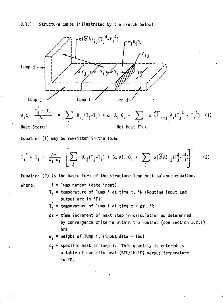
3.1.1 Structure Lumps (illustrated by the sketch below)
Lump j
Lump j Lump i
wTi - TiAt
Heat Stored
Lump j
AT j AT(T/ - Ti4)
Net Heat Flux
Equation (1) may be rewritten in the form:
E (-A), Q, +_ J
(2)
Equation (2) is the basic form of the structure lump heat balance equation.
where: 1 = lump number (data input)T. = temperature of lump i at time T, °R (Routine input and
output are in °F)iT. = temperature of lump i at time T + AT, °R
AT = time increment of next step in calculation as determinedby convergence criteria within the routine (see Section 3.2.1)hrs
w.| = weight of lump i, (input data - Ibs)
c.| = specific heat of lump i. This quantity is entered asa table of specific heat (BTU/lb-°F) versus temperaturein °F.
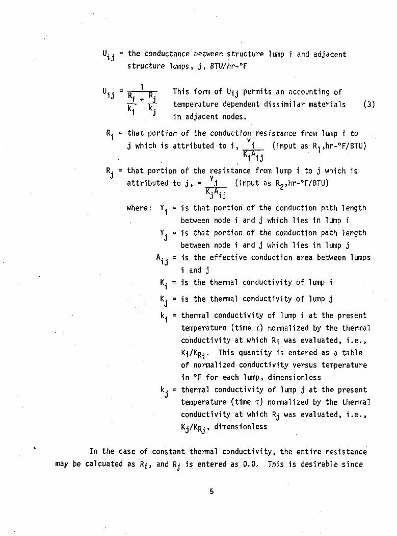
U. . = the conductance between structure lump i and adjacent' J
structure lumps, j, BTU/hr-°F
U1j a R - RT Tll1s ^oni) °^ "U permits an accounting ofir- TT" temperature dependent dissimilar materials (3)1 1J in adjacent nodes.
R.. = that portion of the conduction resistance from lump i toYj which is attributed to i, i (input as R, ,hr-°F/BTU)~ '
R. = that portion of the resistance from lump i to j which isattributed to j , = Yj (input as R2>hr-°F/BTU)
KJAiJwhere: Y. = is that portion of the conduction path length
; between node i and j which lies in lump iY. = is that portion of the conduction path lengthJ
between node i and j which lies in lump jA.. = is the effective conduction area between lumps
• Ji and j
K.. = is the thermal conductivity of lump i
K.J = is the thermal conductivity of lump j
k. = thermal conductivity of lump i at the presenttemperature (time T) normalized by the thermalconductivity at which R-j was evaluated, i.e.,KJ/KR. . This quantity is entered as a tableof normalized conductivity versus temperaturein °F for each lump, dimensionless
k. = thermal conductivity of lump j at the presenttemperature (time T) normalized by the thermalconductivity at which Rj was evaluated, i.e.,KJ/KR-- , dimensionless
In the case of constant thermal conductivity, the entire resistancemay be calcuated as Rf, and Rj is entered as 0.0. This is desirable since
it saves data space in the computer core.
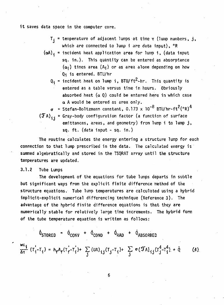
T. = temperature of adjacent lumps at time T (lump numbers, j,which are connected to lump 1 are data input), °R
(ctA).j = incident heat application area for lump i, (data inputsq. in.). This quantity can be entered as absorptance(a ) times area (A^) or as area alone depending on howQi is entered. BTU/hr
Q.J = incident heat on lump i, BTU/ft^-hr. This quantity isentered as a table versus time in hours. Obviouslyabsorbed heat (a Q) could be entered here in which casea A would be entered as area only.
a = S.tefan-Boltzmann constant, 0.173 x 10"8 BTU/hr-ft2(°R)4
(3*A).. = Gray-body configuration factor (a function of surfaceemittances, areas, and geometry) from lump i to lump j,sq. ft. (data input - sq. in.)
The routine calculates the energy entering a structure lump for eachconnection to that lump prescribed in the data. The calculated energy issummed algebratically and stored in the TSQRAT array until the structuretemperatures are updated.
3.1.2 Tube LumpsThe development of the equations for tube lumps departs in subtle
but significant ways from the explicit finite difference method of thestructure equations. Tube lump temperatures are calculated using a hybridimplicit-explicit numerical differencing technique (References). Theadvantage of the hybrid finite difference equations is that they arenumerically stable for relatively large time increments. The hybrid formof the tube temperature equation is written as follows:
^STORED = QCONV + ^COND + QRAD + ^ABSORBED
Tr1 (T'.-T.) = hfAf(T'-T!)+ E(UA) (T.-T.J+ E »C3AL.(rf-Tjl.+Q (4).*»' ii i i i i • ij j i • ij j ij j
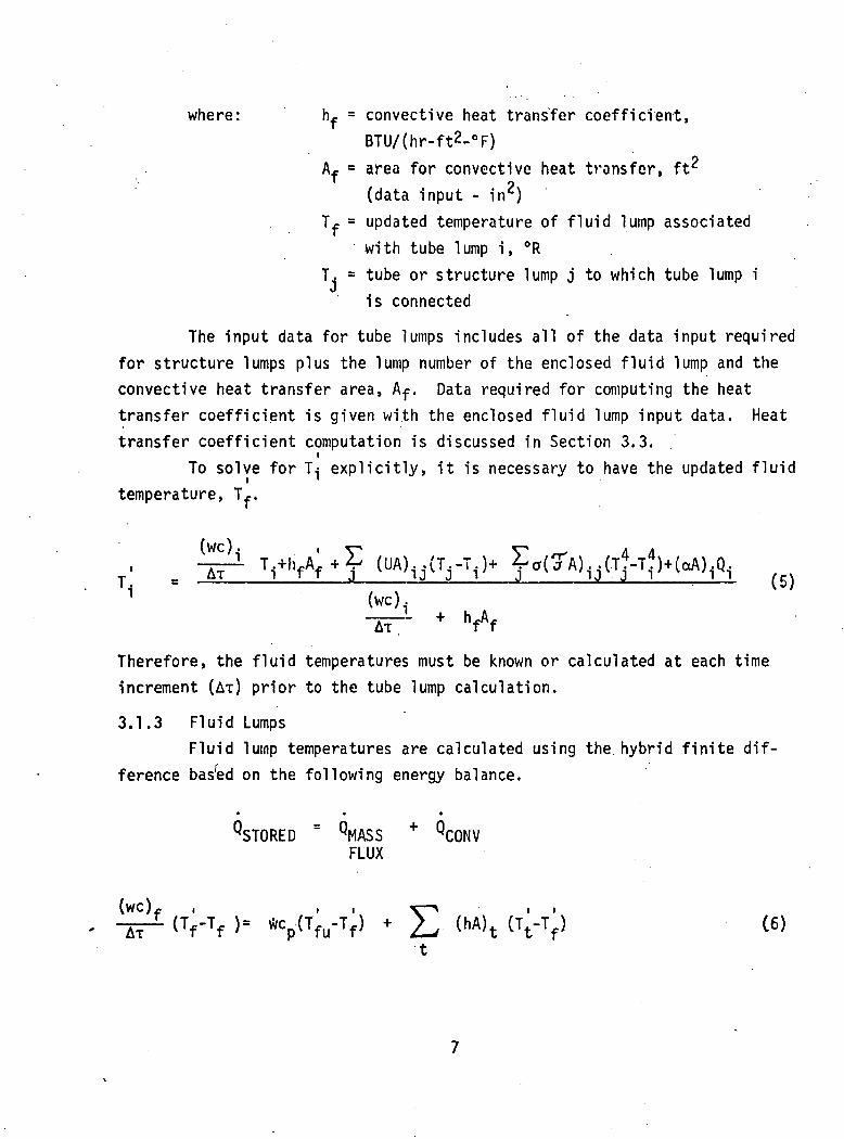
where: h^ = convective heat transfer coefficient,BTU/(hr-ft2-°F)
Af ° area for convective heat transfer, ft2
(data input - in )Tf = updated temperature of fluid lump associated
with tube lump i, °RT. = tube or structure lump j to which tube lump i
is connected
The input data for tube lumps includes all of the data input requiredfor structure lumps plus the lump number of the enclosed fluid lump and theconvective heat transfer area, Af. Data required for computing the heattransfer coefficient is given with the enclosed fluid lump input data. Heattransfer coefficient computation is discussed in Section 3.3.
To solve for T.J explicitly, it is necessary to have the updated fluidtemperature, Tf.
(we),
Therefore, the fluid temperatures must be known or calculated at each timeincrement (AT) prior to the tube lump calculation.
3.1.3 Fluid LumpsFluid lump temperatures are calculated using the hybrid finite dif-
ference bashed on the following energy balance.
^STORED = QMASS + QCONVFLUX
(wc)f , , , r—\ , ,
-K-t <VTf )• %(Tfu-Tf> + L, (hA)t IVV
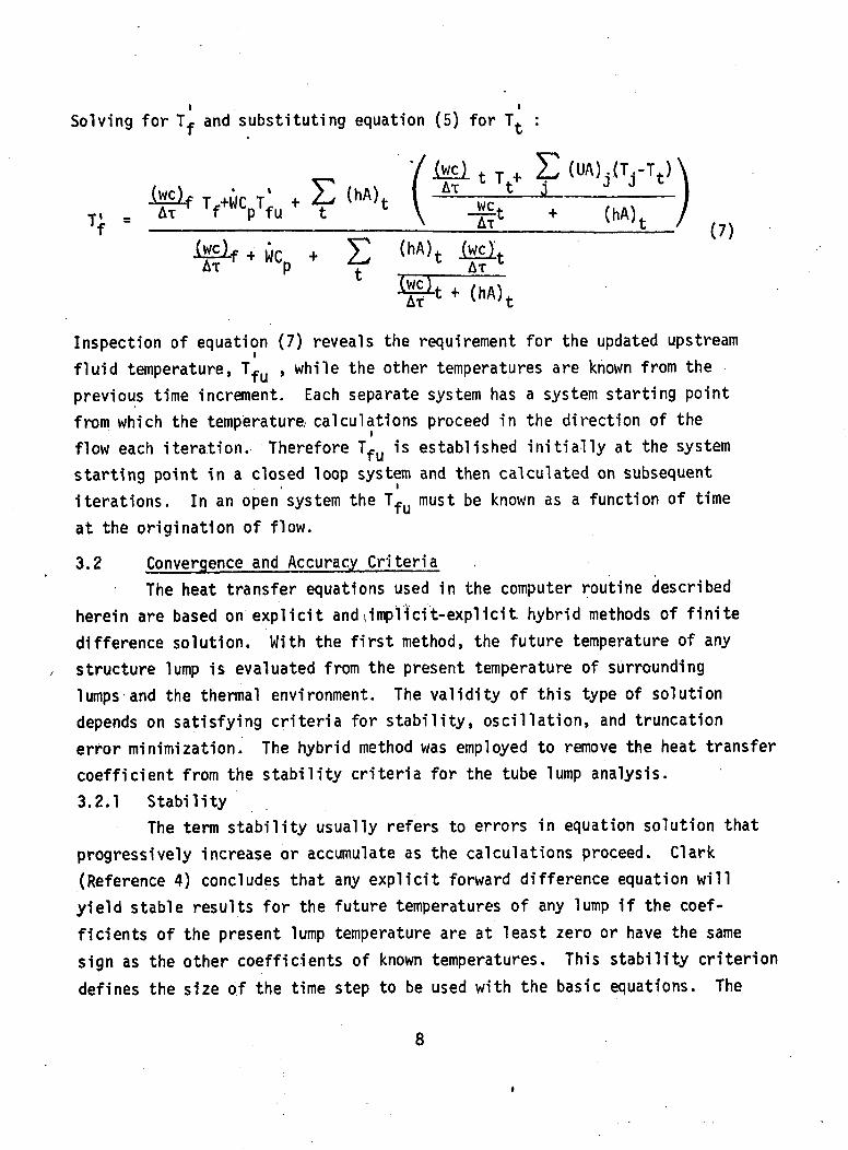
Solving for T and substituting equation (5) for
^ ' /iwci t T+ E (UA),(T rT t)
l-cl- VUCpT;u * E (HA)t ( AT^ \
+ E (hA)tp t — AT
AT - -t / (?)
i c
Inspection of equation (7) reveals the requirement for the updated upstreamfluid temperature, Tf , while the other temperatures are known from theprevious time increment. Each separate system has a system starting pointfrom which the temperature calculations proceed in the direction of theflow each iteration. Therefore Tfu is established initially at the systemstarting point in a closed loop system and then calculated on subsequentiterations. In an open system the Tf(j must be known as a function of timeat the origination of flow.
3.2 Convergence and Accuracy CriteriaThe heat transfer equations used in the computer routine described
herein are based on explicit and,implicit-explicit hybrid methods of finitedifference solution. With the first method, the future temperature of anystructure lump is evaluated from the present temperature of surroundinglumps and the thermal environment. The validity of this type of solutiondepends on satisfying criteria for stability, oscillation, and truncationerror minimization. The hybrid method was employed to remove the heat transfercoefficient from the stability criteria for the tube lump analysis.3.2.1 Stability
The term stability usually refers to errors in equation solution thatprogressively increase or accumulate as the calculations proceed. Clark(Reference 4) concludes that any explicit forward difference equation willyield stable results for the future temperatures of any lump if the coef-ficients of the present lump temperature are at least zero or have the samesign as the other coefficients of known temperatures. This stability criteriondefines the size of the time step to be used with the basic equations. The
8
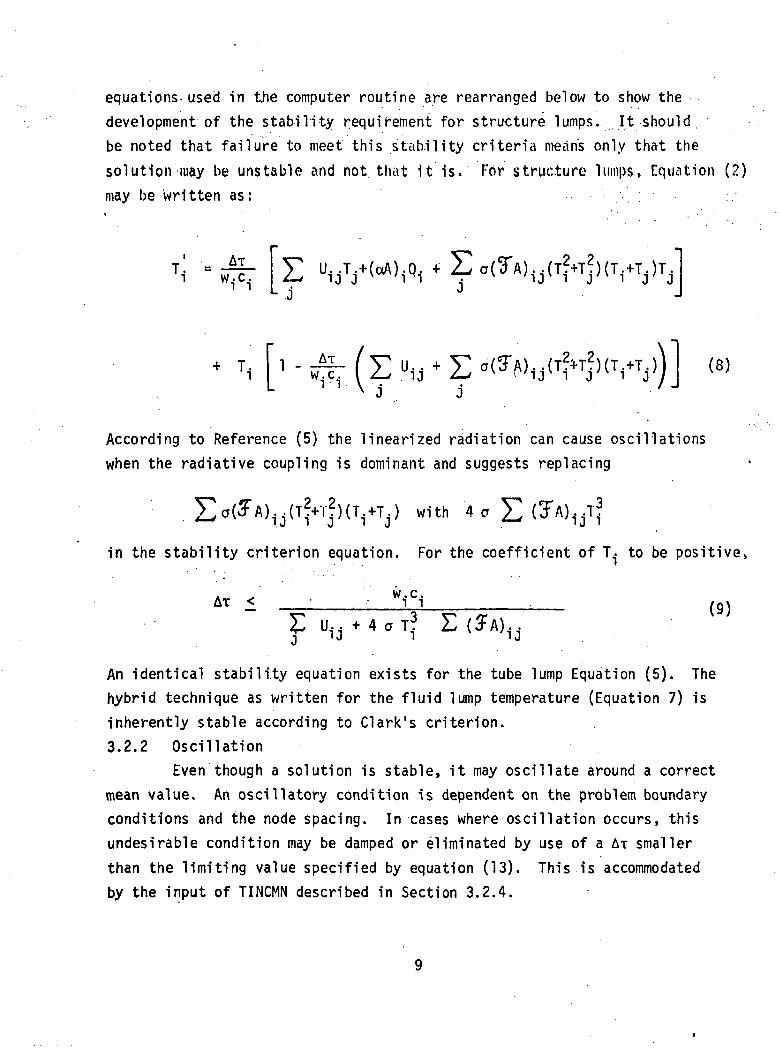
equations-used in the computer routine are rearranged below to show thedevelopment of the stability requirement for structure lumps. It shouldbe noted that failure to meet this stability criteria means only that thesolution may be unstable and not that it is. For structure lumps, Equation (2)may be written as: ..
. .L J
"ijV(aA)1Q1 * ?a(TA)1J(TH)(Ti+TJ)TJ
T.. (8)
According to Reference (5) the linearized radiation can cause oscillationswhen the radiative coupling is dominant and suggests replacing
with '4
in the stability criterion equation. For the coefficient of T.- to be positive,
AT < ' • WTCiU i j + 4 ° T ? EC?A). .
An identical stability equation exists for the tube lump Equation (5). Thehybrid technique as written for the fluid lump temperature (Equation 7) isinherently stable according to Clark's criterion.3.2.2 Oscillation
Even though a solution is stable, it may oscillate around a correctmean value. An oscillatory condition is dependent on the problem boundaryconditions and the node spacing. In cases where oscillation occurs, thisundesirable condition may be damped or eliminated by use of a AT smallerthan the limiting value specified by equation (13). This is accommodatedby the input of TINCMN described in Section 3.2.4.
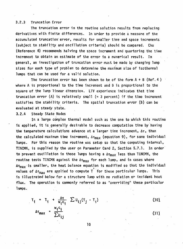
3.2.3 Truncation ErrorThe truncation error in the routine solution results from replacing
derivatives with finite differences. In order to provide a measure of theaccumulated truncation" error, results for smaller time and space increments(subject to stability and oscillation criteria) should be compared. Chu(Reference 6) recommends halving the space increment and quartering the timeincrement to obtain an estimate of the error 1n a numerical result. Ingeneral, an investigation of truncation error must be made by changing lumpsizes for each type of problem to determine the maximum size of isothermallumps that can be used for a valid solution.
The truncation error has been shown to be of the form A + B (Ref . 4 )where A is proportional to the time increment and B is proportional to thesquare of the lump linear dimension. LTV experience indicates that timetruncation error (A) is relatively small (* 3 percent) if the time incrementsatisfies the stability criteria. The spatial truncation error (B) can beevaluated at steady state.3.2.4 Steady State Nodes
In a large complex thermal model such as the one to which this routineis applied, it is generally desirable to decrease computation time by havingthe temperature calculations advance at a larger time increment, AT, thanthe calculated maximum time increment, AT,nax (equation 9), for some individuallumps. For this reason the routine was setup so that the computing interval,TINCMN, is supplied by the user on Parameter Card 2, Section 5.7.1. In orderto prevent oscillation in those lumps having a ATmax less than TINCMN, theroutine tests TINCMN against the ATmax for each lump, and in cases whereATmax is smaller, the heat balance equation is modified so that the individualvalues of ATmax are applied to compute T for these particular lumps. Thisis illustrated below for a structure lump with no radiation or incident heatflux. The operation is commonly referred to as "overriding" these particular1 umps .
, - TI + EVW ooiwici
ATmax = TT OH
10
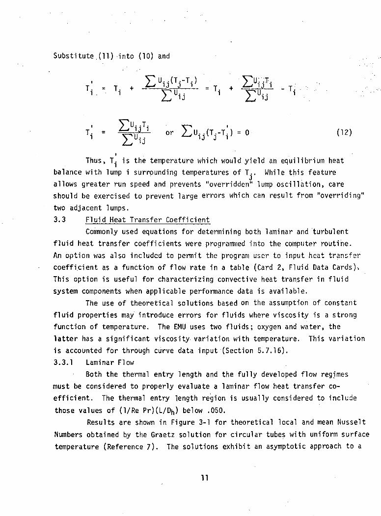
Substitute.(11) into (10) and
T - T 4- *~~* -,'J J •. V - T -4- *"** ' J ' Ti . • i VU.. " '1 T'Ml.T" " 'i
Thus, T. is the temperature which would yield an equilibrium heatbalance with lump i surrounding temperatures of T.. While this feature
Jallows greater run speed and prevents "overridden" lump oscillation, careshould be exercised to prevent large errors which can result from "overriding"two adjacent lumps.3.3 Fluid Heat Transfer Coefficient
Commonly used equations for determining both laminar and turbulentfluid heat transfer coefficients were programmed into the computer routine.An option was also included to permit the program user to input heat transfercoefficient as a function of flow rate in a table (Card 2, Fluid Data Cards)'.This option is useful for characterizing convective heat transfer in fluidsystem components when applicable performance data is available.
The use of theoretical solutions based on the assumption of constantfluid properties may introduce errors for fluids where viscosity is a strongfunction of temperature. The EMU uses two fluids; oxygen and water, thelatter has a significant viscosity variation with temperature. This variationis accounted for through curve data input (Section 5.7.16).3.3.1 Laminar Flow
Both the thermal entry length and the fully developed flow regimesmust be considered to properly evaluate a laminar flow heat transfer co-efficient. The thermal entry length region is usually considered to include
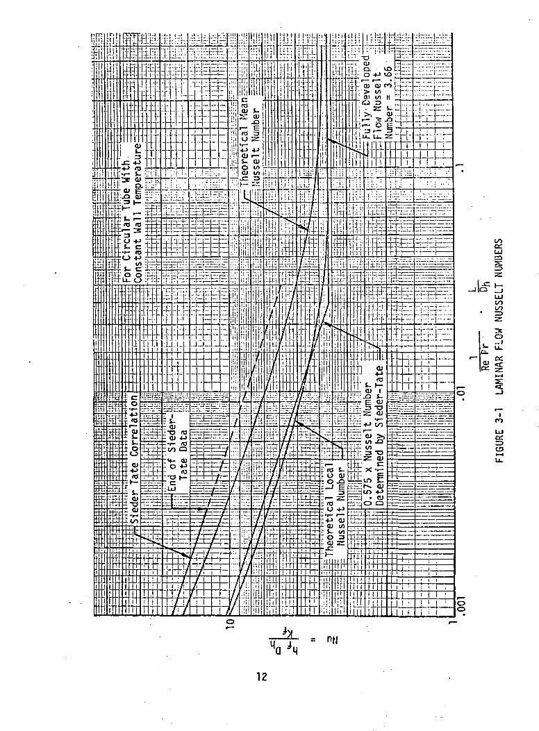
those values of (I/Re Pr)(L/Dn) below .050.Results are shown in Figure 3-1 for theoretical local and mean Nusselt
Numbers obtained by the Graetz solution for circular tubes with uniform surfacetemperature (Reference 7). The solutions exhibit an asymptotic approach to a
11
!_
O.
O)a:
UJ
s:
oo
o
Ico
a:
12
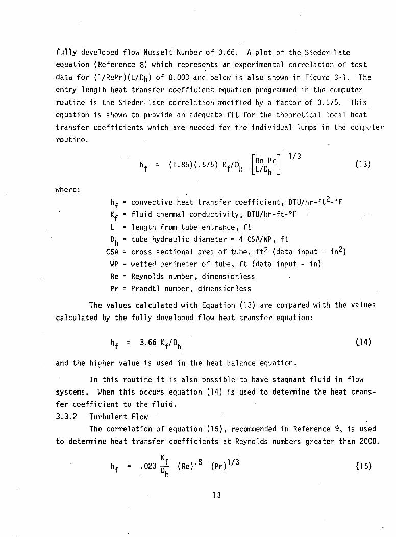
fully developed flow Nusselt Number of 3.66. A plot of the Sieder-Tateequation (Reference 8) which represents an experimental correlation of testdata for (l/RePr)(L/Dn) of 0.003 and below is also shown in Figure 3-1. Theentry length heat transfer coefficient equation programmed in the computerroutine is the Sieder-Tate correlation modified by a factor of 0.575. Thisequation is shown to provide an adequate fit for the theoretical local heattransfer coefficients which are needed for the individual lumps in the computerroutine.
hf = (1.86)(.575) Kf/DhPr 1/3
(13)
where:h.p = convective heat transfer coefficient, BTU/hr-ft2-°FKf = fluid thermal conductivity, BTU/hr-ft-°FL = length from tube entrance, ftDh = tube hydraulic diameter = 4 CSA/WP, ft
CSA = cross sectional area of tube, ft2 (data input - iWP = wetted perimeter of tube, ft (data input - in)Re = Reynolds number, dimensionlessPr = Prandtl number, dimensionless
The values calculated with Equation (13) are compared with the valuescalculated by the fully developed flow heat transfer equation:
hf = 3.66 Kf/Dh
and the higher value is used in the heat balance equation.
(14)
In this routine it is also possible to have stagnant fluid in flowsystems. When this occurs equation (14) is used to determine the heat trans-fer coefficient to the fluid.3.3.2 Turbulent Flow
The correlation of equation (15), recommended in Reference 9, is usedto determine heat transfer coefficients at Reynolds numbers greater than 2000.
hf = .023 (Re)'8 (Pr)1/3 05)
13
In turbulent flow the undeveloped region of heat transfer is short(= 4 diameters) such that for most cnses it will constitute only a smallportion of the total internal hoat transfer region.3.1 Flui jd_Pr_osj; u re_L os s
The flow system pressure loss is calculated by the Fanning equationwith a dynamic head loss factor (K) added. The pressure loss for each fluidlump is calculated by:
AD , ,FLL Pr + pr _ ^ n fjwPlFU-AP = 4 f-K- ^-o— *^ ~5"" "—~~^ —*-—<--—
Uh 2 *
Pm-1 +K1CSA KJ
where f = friction factor 16/Re for Reynolds Numbers less than 2000and is read from input data for Reynolds Numbers greaterthan 2000 (NFFC, Fluid Data Card 2). The laminar flowfriction factor may also be multiplied by FRE, Fluid DataCard 2 to account for non-circular pipe flow.
FLL = fluid lump length (not necessarily equal to tube lump length)K = number of fluid dynamic head lossesw = tube fluid flow rate, Ib/hrHP = wetted perimeter, ft (data input - in)CSA = fluid cross section area, ft2 (data input - in2)Dh = tube hydraulic diameter - 4 CSA/WP, ftp = fluid density, lb/ft3
v = fluid velocity, ft/hr
The fluid lump type cards provide for inputs of (K) which can bedifferent for each fluid lump type. The term is used to account for pressurelosses in tube entrance regions, bends, contractions, and expansions. Entrancepressure losses for varying duct geometries (ReferencelO) may also be specifiedby ( K ) .3.5 Flow System Characterization
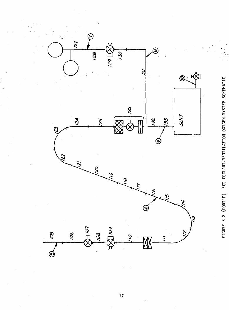
There are three flow systems involved fn the s-ftnulatibn of a crewman
performing an in-flight Extravehicular Activity (EVA). These systems are
the vehicle environmental control system (ECS} coolant loop, the ventilation
oxygen loop and the oxygen purge system.
14
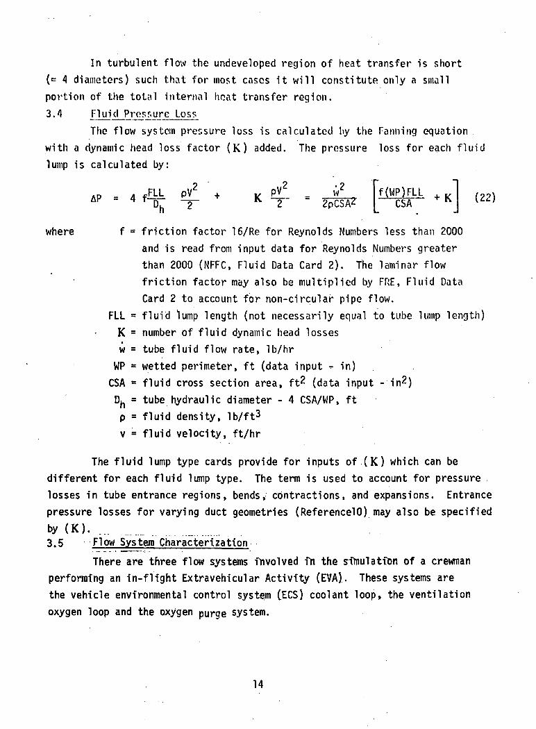
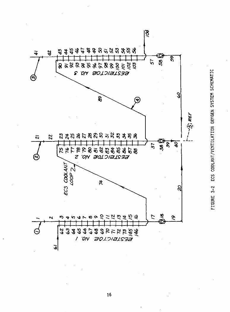
Only a short segment of the much larger ECS coolant loop is simulated.The ECS coolant loop is only important in the analyses to the extent that it.,interacts with the ventilation oxygen loop at the restrictors. Thereforethe ECS coolant loop is characterized beginning upstream of the first restrictorand ending downstream of the third restrictor. Notice in Figure 3-2 that thecoolant loop and ventilation oxygen loop are arranged for parallel flow throughthe restrictors. The coolant loop adds heat to the oxygen through the res-trictors to assure that the oxygen leaves the restrictors in the gaseousphase.
As with the coolant loop, the complete ventilation oxygen loop is notcharacterized. The cryogenic oxygen tanks and the tubing connecting the tanksto the restrictors are omitted. Characterization of the ventilation oxygenloop begins at the inlet to the restrictors and includes the components atthe EVA/IVA panel, EVA umbilical, suit control unit (SCU), suit, and pressurecontrol valve (PCV). The condition (temperature and pressure) of the oxygenis specified in the input data for each restrictors inlet. Due to the mannerIn which the cryo tanks are manifolded, the inlet temperature and pressureof two of the restrictors should always be input as coming from a. single tank.The restrictors are in parallel and the flowrate in each restrictor is iterateduntil the pressure drops are equal and the sum of the restrictor flows isequal to the total oxygen flow. Total oxygen flow is determined from calcu-lations on the SCU fixed orifice.
The third flow system, the Oxygen Purge System (OPS) (Figure 3-3),is identical to the OPS used during lunar surface EVA. High pressure oxygenis regulated by the suit purge control valve which can be set for either a4 or 8 pound per hour suit flow. The OPS backs up the ventilation oxygensystem in case of flow stoppage or excessive carbon dioxide build-up in thesuit.3.6 Crewman Characterization
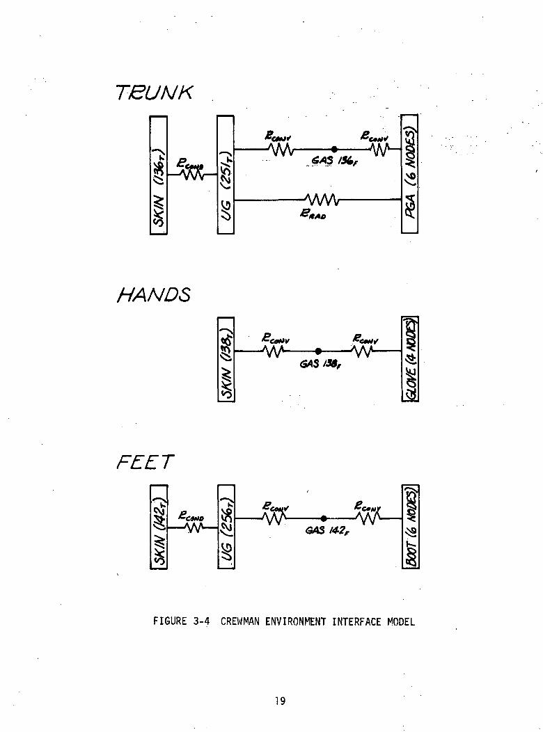
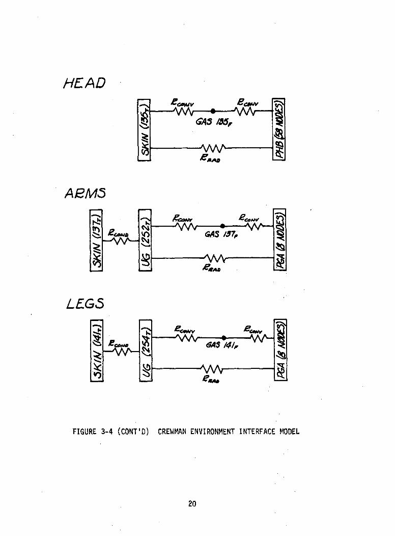
The simulator has incorporated the 41-node metabolic man simulationdeveloped by the National Aeronautics and Space Administration (NASA) - MannedSpacecraft Center (MSC) (Reference 11 ). Program logic change was necessary tointerface the 41-node man with the simulator but the basic relationshipsrepresenting the thermal regulatory processes are unchanged. The principlearea of significant change is at the man's skin/environment interface. Figure3-4 describes the man's skin/environment as modeled in the simulator.
15
I 1 1 1 I I I I I 1 1 1 1 1 1 f
u.*1
<
Iooo
Ul
oo
CD
SoI—I
<c
ooo
o
CVI
roUlDC
g
16
ot—I
«t
oco
coCO
zrUJC3
O
2TO(—1
&
ooo
oo
CVJ
CO
UJocCD
17
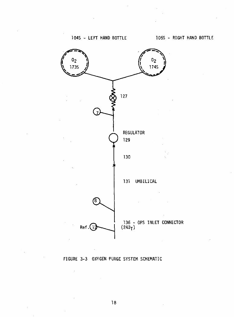
104S - LEFT HAND BOTTLE 105S - RIGHT HAND BOTTLE
REGULATOR
129
130
131 UMBILICAL
136 - OPS INLET CONNECTOR(242T)
FIGURE 3-3 OXYGEN PURGE SYSTEM SCHEMATIC
18
TBUNK
8I
Si
§
~CM/'—wv—• -w-
AWV
HANDS
—w- AA^
C9MO
Kfou^
—^A^
FIGURE 3-4 CREWMAN ENVIRONMENT INTERFACE MODEL
19
HEAD
I1
—• Vy/V—IGAS /95r
OQ
ASMS
vs^yv-J
AW
LEGS
£/NM/ _• W^-
AAAr ^§
FIGURE 3-4 (CQNT'D) CREWMAN ENVIRONMENT INTERFACE MODEL
20
All forty-one man temperatures, temperature averages of the skin and
muscle plus eleven other variables to determine the man's relationship to his
environment are output at each print interval. .
3.7 Component Characterization .
To simulate the ventilation oxygen system-and the OPS, individual
components must be simulated in order to calculate system pressure drop and
temperature rise. The portion of the vehicle coolant loop of interest involves
only a section of three eighths inch (outside diameter) tubing which requires
no special characterization.3.7.1 Oxygen Restrictor
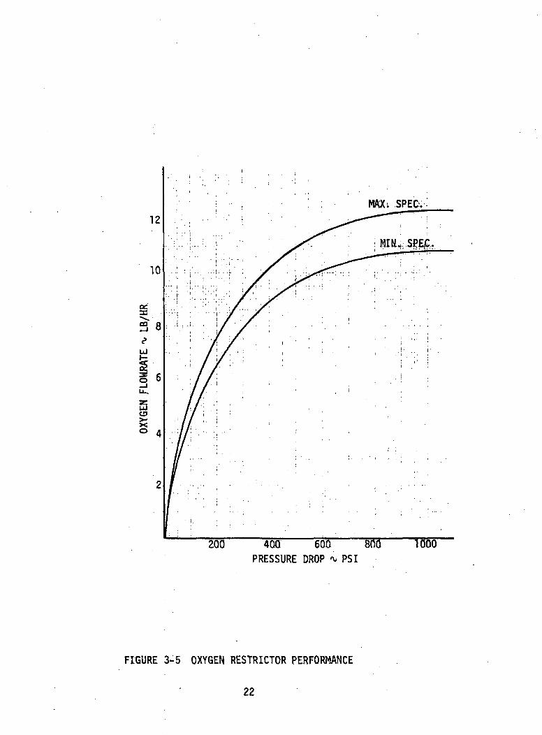
The restrictors are small diameter tubes (.019 inch inside diameter)which are wrapped around the 3/8 inch vehicle coolant line. Most of thesystem pressure is dropped across the restrictors. .Figure 3-5 presents the per-formance of the three restrictors in parallel for a supply pressure of 865 psia.3.7.2 Extravehicular/Intravehfcular Activity Panel
The panel is composed of three major components: shut-off valve,pressure regulator, and quick disconnect. Only the pressure regulator requiresspecial handling with respect to component characterization. The pressureregulator drops the upstream pressure to 100 +_ 5 psig for the normal range offlowrate (10 to 12 Ib/hr). Logic is written into program which changes thedownstream regulator pressure to a user input value as long as the upstreampressure is greater than the input value. If the upstream regulator pressureis less than the control unit value requested by the user, the regulator isfull open and does not control the downstream regulator pressure. When theregulator is full open, a small pressure drop (* 3 psi) occurs across theregulator and is Incorporated in the pressure regulator simulation.3.7.3 Umbilical
The umbilical delivers the oxygen to the SCU after pressure regulationat the EV/IV panel (Section 3.7.2). Since the oxygen supply system is a blowdownsystem, a return oxygen hose is not required. The umbilical includes electricalcables which are placed around the oxygen hose and then the entire umbilical iscovered with multilayer insulation. A tether is incorporated in the umbilicalto carry all longitudinal loads. The oxygen hose is 0.9 inch outside diameterand 0.375 inch inside diameter.
21
200 400 600 800PRESSURE DROP * PSI
1000
FIGURE 3-5 OXYGEN RESTRICTOR PERFORMANCE
22
3.7.4 Suit Control Unit (SCU)
The SCU consists of a filter, a shutoff valve, an orifice, a suitconnector, and-two pressure switches. Flow from the umbilical 1s metered bythe 0.04 to 0.043 inch diameter SCU orifice. The pressure switches are placedone on either side, of the SCU orifice to warn the crewman of decreasing suitpressure or decreasing purge flow pressure.3.7.5 Suit
The crewman's space suit is composed of the pressure garment assembly(PGA) and the integrated thermal/meteoroid garment (ITMG). The flow-splitsin the PGA for the suited modes were furnished in the subroutines of the41-node metabolic man program (NASA) and were used without change. Likewise,the convection and radiation heat transfer between the suit wall and crewman'sundergarment are calculated as in the NASA program with provisions added tohandle multi-node suit areas around a single skin compartment.
The PGA may be assumed to have leakage by inputting a curve of leakagerate versus time. Gas leakage leaves the PGA and the gas loop at the outletgas connector at a humidity which is the average of the inlet and outlethumidities of the suit gas. Pressure drop through the suit is calculatedusing the following equation:
Ap = C _LH (ft) 7
' Mnwhere AP = the pressure drop through the suit, psi
Tin = gas temperature into the suit, °RPin = 9as system Pressure into the suit, psiaW = gas flowrate, LB/hr
Suggested values for C7 = 1.062E-5 and N7 = 1.862
3.7.6 Pressure Control ValveA pressure control valve (PCV) is used to control the suit pressure
during normal operation of primary oxygen supply system. The PCV incorporatesa manual shut-off to override the valve, if desfrable. In the event the PCVfails to open, the suit to ambient pressure difference will remain above3 psi for minimum umbilical flow (10 Ib/hr).3.7.7 Oxygen Regulator
The EMU has two oxygen regulators in which the oxygen is expandedto a lower pressure. The expansion process cools the gas which in turn cools
23
the regulator. The temperature and pressure into the regulator are knownand used to interpolate on a curve to find the enthalpy of the gas enteringthe regulator. An isoenthalpic expansion is assumed as the gas enters theregulator. The user inputs the heat transfer coefficient between the ex-panded gas and the regulator.3.7.8 Oxygen Purge System (OPS) Heater
The heater, heater controller, and battery were deleted in OPS'sassembled for Apollo 14 and subsequent flights. Logic to analyze the heaterwas retained but the data tape was modified to reflect the deletion. Thefollowing paragraph documents the heater as originally used.
The OPS heater is located upstream of the OPS oxygen regulator andpreheats the oxygen before it is expanded in the regulator. Downstream of theregulator is a fluid sensor which determines when the heater is on. The userinputs the heat transfer coefficient between the gas and heater element andthe heater power. Two sensor set point temperatures (TSEN1, TSEN2) are input.If the sensor temperature is below TSEN1 and increasing, heater power willbe maintained at a constant value (user input) until the TSEN2 valve isexceeded. If the sensor temperature is above TSEN2 and decreasing, the heaterremains off until the sensor temperature drops below TSEN1. The heater maybe on or off if the sensor temperature is within the TSEN1 to TSEN2 bandas explained above.3.8 Consumables Characterization
The simulator monitors the depletion of the oxygen in the OPS tank.OPS oxygen is the only consumable of interest during a Command Module EVA.The user inputs the initial mass of the oxygen and the simulator substractsthe quantity used and outputs the quantity remaining. The oxygen and oxygenbottle are entered as structure lumps with the heat transfer coefficient,initial pressure, and volume input. Bottle pressure is updated each iterationto account for. temperature and/or mass changes. Mass of the oxygen initiallyin the OPS oxygen bottles is input as the product of the mass times the specificheat as described on the structure type data card for the oxygen. In the base-line thermal model, the initial mass of the oxygen is split equally betweenthe two OPS bottles. An average temperature out of the OPS bottles is usedsince the OPS bottles blowdown simultaneously.
24

3.9 Oxygen Bottle Slowdown CharacterizationThe EMU OPS contains two spherical oxygen bottles which comprise
.an'emergency or purge supply. The flowrate from the bottles 1s known as- afunction of time. The OPS oxygen flowrate is determined by a purge reliefvalve placed 1n the right hand side, oxygen, suit outlet connector.
The increase in stored energy of the gas Is, semantlcally-:
Increase inStored Energyof Gas in Bottle
Energy Added toGas From Bottle
Energy of Gas.Leaving Bottle
Using the above equation the temperature of the gas is calculated. This temp-erature and the last bottle pressure value is used to interpolate on acompressibility factor curve. The gas temperature and mass remain constantwhile the pressure and compressibility factor are Interated until the pressureon successive iterations is within DPTOL.
The heat transfer coefficient Inside each oxygen bottl.e is Inputand is constant for a mission.3.10 Heat Leak Calculation
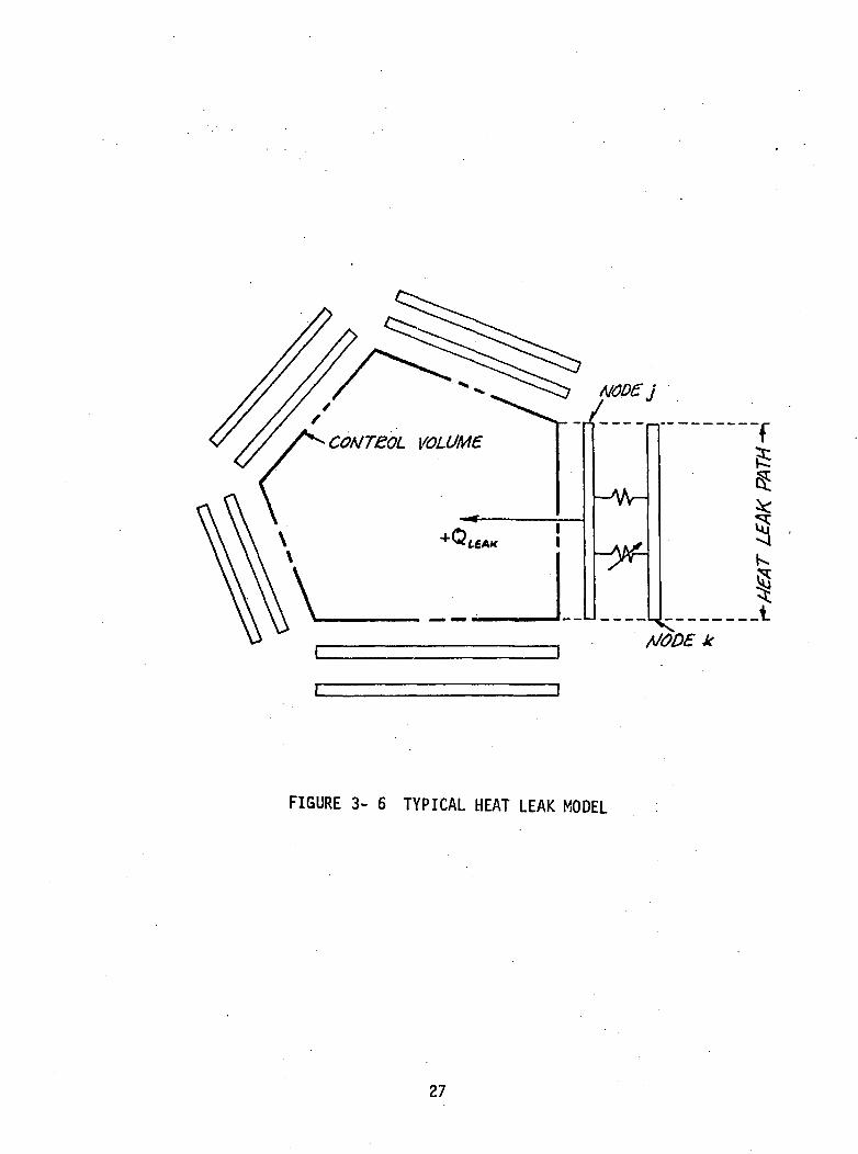
The EMU simulator has the capability of calculating the heat fluxbetween any two nodes. Data input format (see Section 5.7.6) permits theuser to group pairs of nodes to create the desired control volume. Figure3- 6 presents a typical heat leak model to calculate the heat transferredacross the boundary of a control volume. The input data would be set up withone group consisting of five heat leak paths. Semantically, the analysisper heat leak path is:
Energy EnteringThe
Control Volume
Energy ConductedTo Node j
From Node K
Energy RadiatedTo Node j
From Node k
Energy StoredBy Node j
Notice that the heat leak into the control volume (or from node k to node j)is assumed positive.
In the EMU simulator, heat leak groups for the-Lunar ExtravehicularVisor Assembly (LEVA), Pressure Garment Assembly (PGA), and several other
25
components of interest are set up. There is no program limit on the numberof groups or the number of heat leak paths (node pairings) per group. Onerestriction is made; and it requires the first group to be the LEVA heat leakgroup. This requirement arises because the LEVA visor material transmitssolar wavelength energy through "node j". The energy entering the LEVA throughthe visors is automatically added to the first heat leak group. There areother unique features associated with the visor analysis as explained inSection 3.12.
To identify a heat leak path the user enters the two nodes (j and k)and a connection number for conduction and radiation between nodes j and k.The connection number is determined from node j lump card (tube or structure)by counting, from left to right, the "to" lumps to node k. It is necessarythat the user know which node j to node k connection is the conduction connectionand which is radiation to properly assign the connection numbers in the heatleak data. A check of the type data for node j will aid the user in establishingthe kind of connection made to node j. Notice, when node j is connected to nodek by conduction and radiation, node k will appear twice as a "to" lump on thenode j lump card. Therefore the connection numbers for a node pair in the heatleak data connot be equal.3.11 Heat Storage Calculation
The EMU simulator has the capability of calculating the energy storedby a node from initial condition (i.e., initial temperature on Tump card)to some later time. Net heat stored by a node at time, T, is. calculated bythe following equation:
Qstored,j = WCj, at T (Tj, at T " Tj, at r=T.V
If the computer run is interrupted and restarted, the initial temperatureused in the above equation is identical to the temperature input on the tubeor structure lump card. The WC product is the current value including anyadjustments prescribed by the Time-Variant Mass Data and/or the specificheat curve data. The user inputs the node number and the applicable iden-tifying code (see Section 5.7.7) of the nodes for which heat storage calcu-lations are desired. A single value of heat storage will be output whenseveral nodes are grouped together. There is no program limit on the numberof groups or the number of nodes per group that may be input.
26
\
^CONTEOL VOLUME.
^
i TTT '
1
-AAr-
-yf-
H
f1is:^Jj
Kr^.\
t'OD£ Jf
FIGURE 3- 6 TYPICAL HEAT LEAK MODEL
27
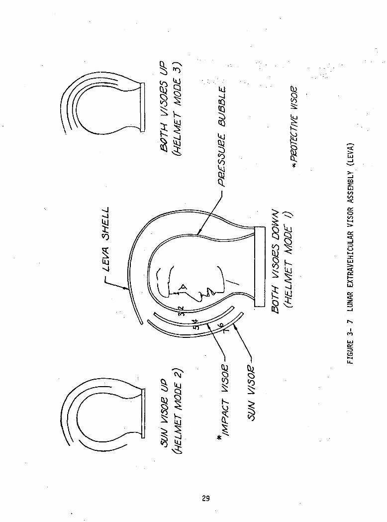
3.12 LEVA Visor AnalysisThe crewman's face is protected by two retractable visors and a
pressure bubble. The retractable visors have special coatings which transmitradiation 1n the visible spectrum and block Infrared radiation. A visoranalysis is required to calculate the fraction of external incident energyabsorbed by each visor and the crewman's face. The analysis is complicatedby the fact that the visors may be positioned in three unique configurations(see Figure 3- 7): both visors down, sun visor up, and both sun visor andimpact visor up.
The fraction of incident energy absorbed by a visor surface canbe determined from coating properties and has been done by A. J. Chapmanas recorded in informal documentation received October 1966. Chapmannumbers the surfaces 1 to seven with one being the crewman's face andseven, the outer surface of the sun visor (Figure 3-7). This same con-vention is followed below as well as Chapman's notation of the energyfraction. F.* ' refers to the fraction of the external incident radiationon the ith surface for the kth visor configuration. To shorten the equationswe define Rij as the fraction, l/H-p^p^), where p is the solar reflectivityand i and j are visor surfaces.
Each node on the visor and helmet surfaces 1s assigned a positionnumber; one to the total number of nodes on the visor and helmet surfaces.In addition to a position number, the user inputs a position type (seeSection 5.7.8) to associate the correct surface properties with the visor,helmet, and face nodes. The visor analysis is a two band spectral distri-bution analysis with the separation point between solar and infrared radia-tion established by the flux data input from the Environmental Heat FluxRoutine (Reference 12).
With both visors retracted - n = 1
p 0) _ _ R . p 0) . D p 0) . F 0) _ !Fl T23 R12' F2 " pl Fl ' F3 " '•
Transmlssivity, T«,, is the solar transmissivity of the pressure bubble and,/ _ \in Chapman's development of the F/ ', the assumption was made that T..J = T.^.
With the impact visor down and sun visor up - n = 2
28
<:ui
i00
a:o00
a:g
CO
UJC£
CO
29
F/'K
F (2) =F2
(2) _' o =o
Fl_ (1)f2
T45
i_ft •
P3<^)
F '2)"3
R34
r P - P O )
F (2) = o T R + T R F ]) F (2)F4 P3 T45 ,K34 * T23 K34 h2 h3
F <« = 1.
With sun visor down - n = 3
F (3) _ F (2) F (3)Fl " Fl h5(3) - (2) (3)
~
F (3) .. T67 R56
5
F <3) - D T R + T R f fF6 P5 T67 R56 + T45 R56 F4 F5
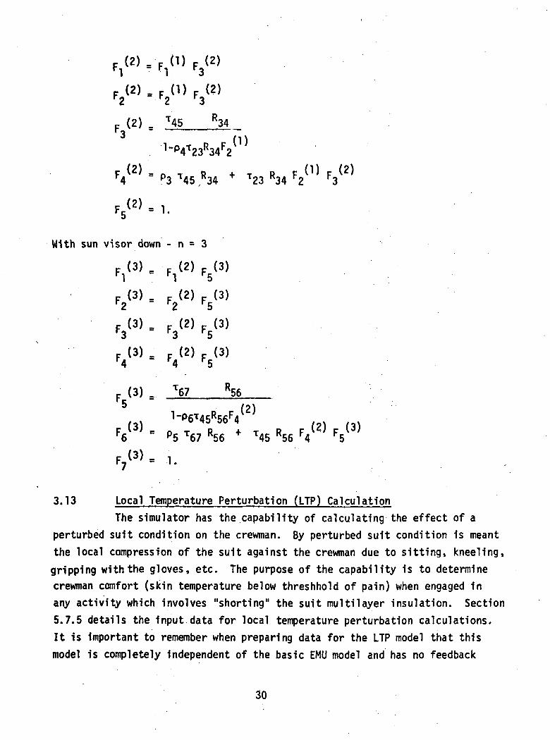
3.13 Local Temperature Perturbation (LTP) CalculationThe simulator has the capability of calculating the effect of a
perturbed suit condition on the crewman. By perturbed suit condition is meantthe local compression of the suit against the crewman due to sitting, kneeling,gripping with the gloves, etc. The purpose of the capability is to determinecrewman comfort (skin temperature below threshhold of pain) when engaged inany activity which involves "shorting" the suit multilayer insulation. Section5.7.5 details the input data for local temperature perturbation calculations.It is important to remember when preparing data for the LTP model that thismodel is completely independent of the basic EMU model and has no feedback
30
to it. Notice should be made that LTP model lump numbers are described in theregular data and that Section 5.7.5 provides additional information whichidentifies certain lump numbers as LTP lump numbers. All LTP model fluid(gas) lumps must be input in tube 21 which satisfies the data input require-ment for a flow tube but the order of fluid lumps in tube 21 is arbitrary.3.14 Thermal Data Options
The simulator has several unique data options which are requiredto describe the thermal model or provide the user flexibility desired.3.14.1 Suit, Gloves, and EV Boots Node Identification
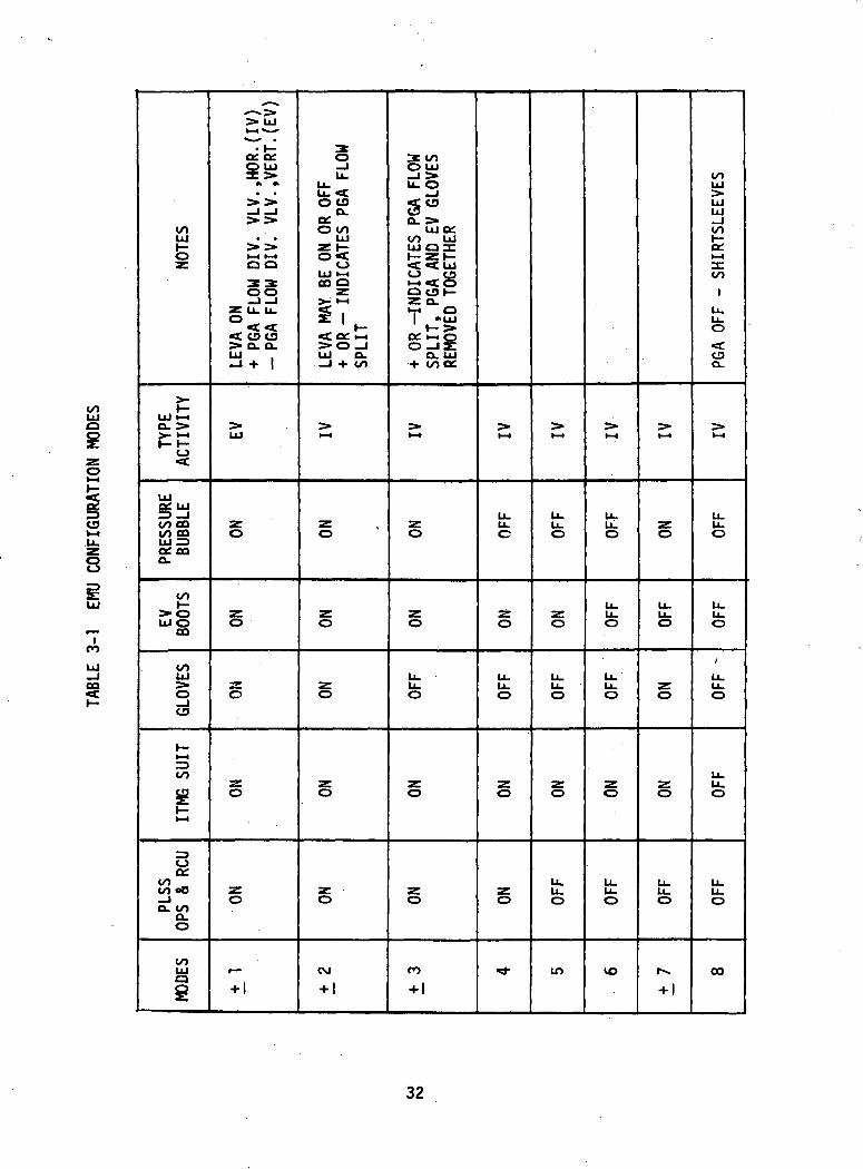
This option is required to simulate the suit donning and doffingprocedures by the crewman in the Command Module (CM). Table 3-1 defines theEMU configuration modes the user may select to include in the mission analysis.Each category of nodes is identified either directly or by the process ofelimination. The pressure bubble nodes are identified through Helmet andVisor Data and with the suit, gloves and boots identified all other nodesare considered to be in the remaining category of Oxygen Purge System (OPS)and Remote Control Plate. All node connections are made in the baseline thermalmodel necessary to analyze EMU Configuration Mode 1. Hhen other modes arespecified the simulator stops analyzing components designated as "off" and notemperature update of nodes identified with "off" components occurs until amode is again selected in which those components are designated as "on".3.14.2 Configuration-Associated Node Identification
This option is similar to the one discussed above but requires moreinput data to establish the same configuration. The user may view this optionas an override of the configurations specified by Table 3-1. As an exampleof how this option may be used, consider Mode 8 which specifies analysisof the crewman in his shirtsleeves only. To obtain the effect of an enclosuresuch as the CM cabin walls on a shirtsleeves crewman, structure nodes repre-senting the wall can be input in the regular data and then associated withConfiguration Mode 8.3.14.3 Heat Flux Curve Assignment
The simulator uses the Environmental Heat Flux Routine (EHFR) describedin Reference 11 as a source of input flux data representing various lunar surfacetopology. The EHFR has geometric heat flux models of the EMU and the ScientificInstruments Module (SIM) Bay which are consistent with the surface areas
31
CO
C9
8
COUlt—0
Ul >->o. >>- *-*f- h-
CJ<c
Ulf^ IIIOf. UJ
CO OQCO COllJ "Uw **Joc OQQ.
COt->oUl O
OQ
COUl
oCD
t— 1
CO
st— 1
oCOCO 08_lQ. CO
Q.O
co3s
>*uJ»-*«*— -
^l> 1 1 1
3C ^^* ««• •
^> 2»^j — j
^* ^>• •
^* ^^HH H-4
00
Z U. Lu
°<<C< CD CD> Q. Q.Ul .-« + 1
Ul
320
Zo
o
o
Jgt
o
•~+l
BJ
LUU.Lu <O CD
CUflf
O COUl
Z I—
CJUl t->OQ O
5 l~<
<dt>O JUl O.-J + CO
(— 1
Zo
^y
o
o
o
Jf^o
CM
+ 1
2 COO Ul_J >U.O
_J
S en
Cu >ui o:
CO UlUl O 3C1— Z 1—
O CDh— 4 ^C rf^
0 CD»-2E Q.
H- >!OC i-iOO — IZ
0. Ul•f coct:
>— i
Zo
Zo
U.
o
o
Z0
CO
+ 1
1— 1
LuLuc
Zo
LuLUO
o
Zo
**"
»— 1
LuLuO
Z0
Lu1 1UL.
o
o
LULU0
in
•— i
u.LuO
LuU.O
Lu
0
O
u_LUO
VO
i— •
Zo
LuLuO
O
O
LUo
"+ 1
COUl^kUlUl—1COI—OL1— I3:CO
1LuLUO^cCDQ.
1— i
U.U.O
U.
0
Lu
0
LuU.O
LULUO
OO
32
of the simulator baseline thermal model. Section 5.7.1, Cards 4 and 5 giveinstructions on the manipulation of the EHFR generated flux data actuallycreating heat flux curves. Although the. curves have been created and areavailable, heat flux curve assignment data is required to apply the flux toa particular thermal model node. The EHFR outputs a contact temperaturewhich represents the lunar surface temperature and this .temperature-Ts;..pre-scribed to a baseline thermal model node which is in contact with- the extra-vehicular boot soles. All EHFR input data is assigned through the datadescribed in Section 5.7.11.3.14.4 Prescribed Wall Temperature Data
The simulator has two types of prescribed wall temperatures excludingthe contact temperature discussed in Section 3.14.3. These prescribed temperaturesare designated as type numbers 10 and 11 in Sections 5.7.12 and 5.7.15- Type10 is used to create a "deep space" node held constant as -4.59.69°F or otherprescribed temperatures where the entire curve can be put on the data tape.Type 11 is used to input SIM bay prescribed temperatures either the completecurve or segments of a large curve contained on an independent input tape.Variable NPRTCD on Card 2 (Section 5.7.1) designates how the SIM bay temperatureswill be input. The simulator will interrogate NPRTCD and, if 1, will readadditional SIM bay temperature data when the largest time of the segment ofthe curve in the computer is less than mission time.3.14.5 Time Variant Node Data
Time variant data allows the user to vary with time the mass of anode and/or the connection between two nodes. This data is a multiplyingfactor applied after variations in specific heat and thermal conductivityhave been taken into account. The time variant mass data is straight forwardwith the user identifying the node and the controlling curve number. If aconnection between two nodes is to be varied, the user must identify the"from" node and specify a connection number. The connection number for anode varies from 1 to the number of "to" nodes listed in the tube and structurelump cards for the node. This option applies to both conduction and radiationconnections for tube and structure nodes.
33
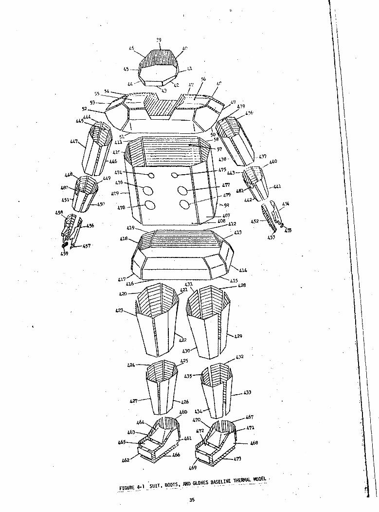
4.0 BASELINE THERMAL MODELA baseline thermal model was created In conjunction with the EMU
simulator and contains the following Items:1. ITMG - Integrated Thermal/Meteoroid Garment (A7LB)2. PGA - Pressure Garment Assembly3. Boots - Lunar EVA Configuration4. Gloves - Extravehicular Configuration5. LEVA - Lunar Extravehicular Visor Assembly6. OPS - Oxygen Purge System7. CREWMAN - 41 Node Man (Ref. 11)8. SIM Bay - Scientific Instruments Module Bay
The model is composed of the three types of nodes described in Section 3.1.The number of flow tubes in the simulator is 21. The simulator is programmedto expect the number of tubes indicated above and program modifications arerequired to change the tube arrangement. Although the user is limited in theextent to which he can change the basic thermal model, important options areopen as to the fineness of the model breakdown and the amount and type ofdata output.
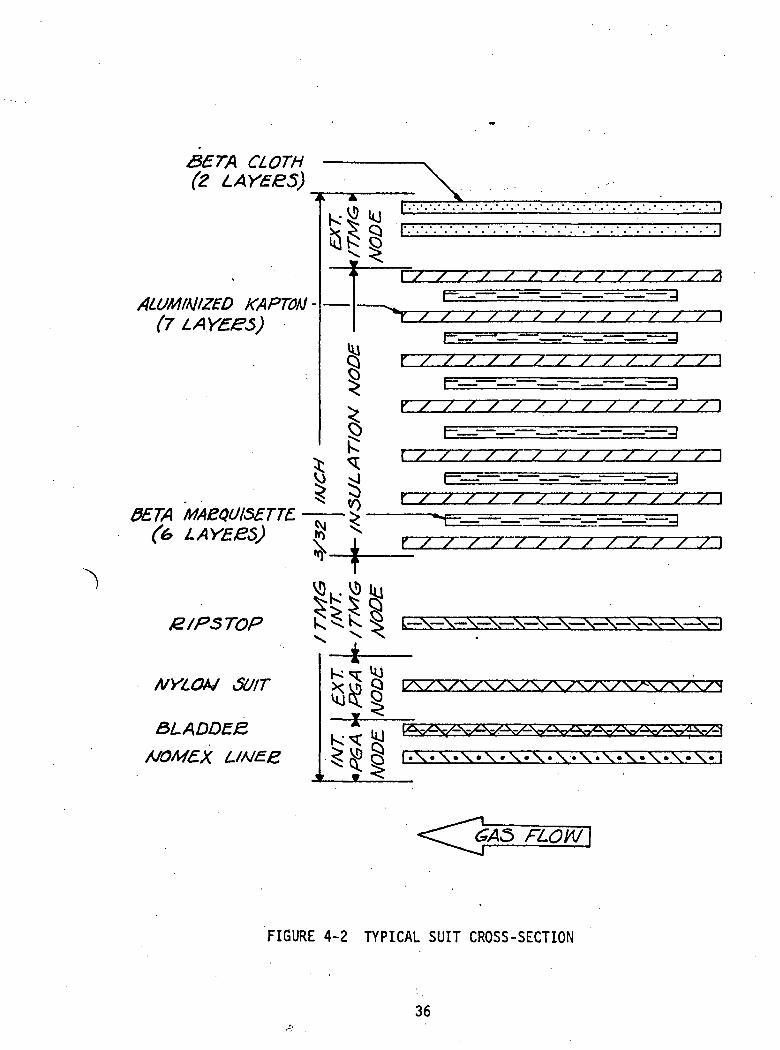
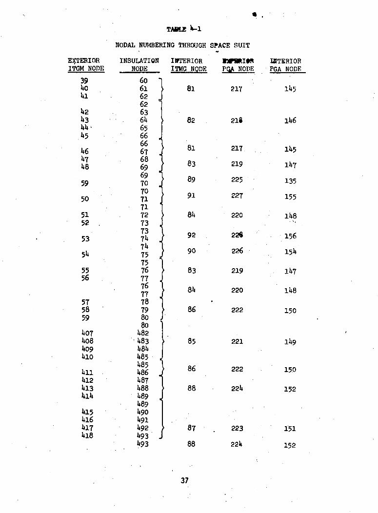
The ITMG, PGA, Boots, and Gloves were broken up into 96 surfacenodes and 5 nodes through the thickness. Figure 4-1 and 4-2 show the surfacenodes as numbered in the baseline thermal model and a typical cross-sectionof the suit. Table 4-1 presents the complete suit node numbering with the"EXTERIOR ITMG NODE" column corresponding to the nodes of Figure 4-1. Themultilayer insulation has the same fineness of nodal breakdown as the exteriorsuit surface, but the three interior node layers have fewer nodes as indicatedby the brackets in Table 4-1 connecting two or more insulation nodes to an"INTERIOR ITMG NODE". Figure 4-1 presents a surface area lumping of a moredetailed geometric suit model found in Reference 13. Conductance values for the
34
;
52
445
447.
i68
473
35
CLOTH(2 LAYZES)
ALUMIWZZD KAPTOM-(7
0ETA
JS/PSTOP
NYLOU 6UIT
&LADDE&
UNE.S.
k A
h-§«i< < vjQ f l
4 >
•• — — »s
tUQ
Q><•
^JO
^
• - • • • • • . ]
• •-!
\ / / / / / / / ' / / / / / X' y^
f— __ __ . _J
•T / / / / / / / / / / / / / I
\ — J "' ' 1
x / / / / / / / / / / / / / \f— \
Y / / / / / / / / / / / / / \
{~ '__ — — - ' _ f
/"/"'/ / / / / / / / / / \
/ / / / / / / / y
v-v-x—N-—\—\—\—\—\—\—x
GAS FLOW
FIGURE 4-2 TYPICAL SUIT CROSS-SECTION
36
TAflLE
NODAL NUMBERING THROUGH SPACE SUIT
E3JTERIORITGM NODE
391*01*1
1*21*31*1*-1*5
1*6U71*8
59
50
5152 .
53
51*
5556
575859
1*071*081*091*10
1*111*121*131*11*
1*151*161*171*18
INSULATION INTERIORNODE ITMG NODE
60 1616262 '6361*6566 .66UVJ67 J6869 I69wx70 J70 ^71 I717273 ,
81
82
81
83
89
• 9!
8»*
73 )7l< J y
71* 175 ) 9°75767776f9*f7778798080 '
1*821*831*8U1*85 ,
83
81*•
86
85
^5 1 a*1*86 J Ob
1*871*881*89 <1*891*901*911*921*93 .
88
' ' 87 .
1*93 88
nrautnPQA NODE
217
218
217
219
225
227
220
22«
226
219
220
222
221
222
221*
223
22k
IHTSRIORPGA NODE
11*5
ll*6
U*5
ll*7
135
155
1U8- % .
156
151*
ll*7
ll*8
150
ll*9
150
152
151
152
37
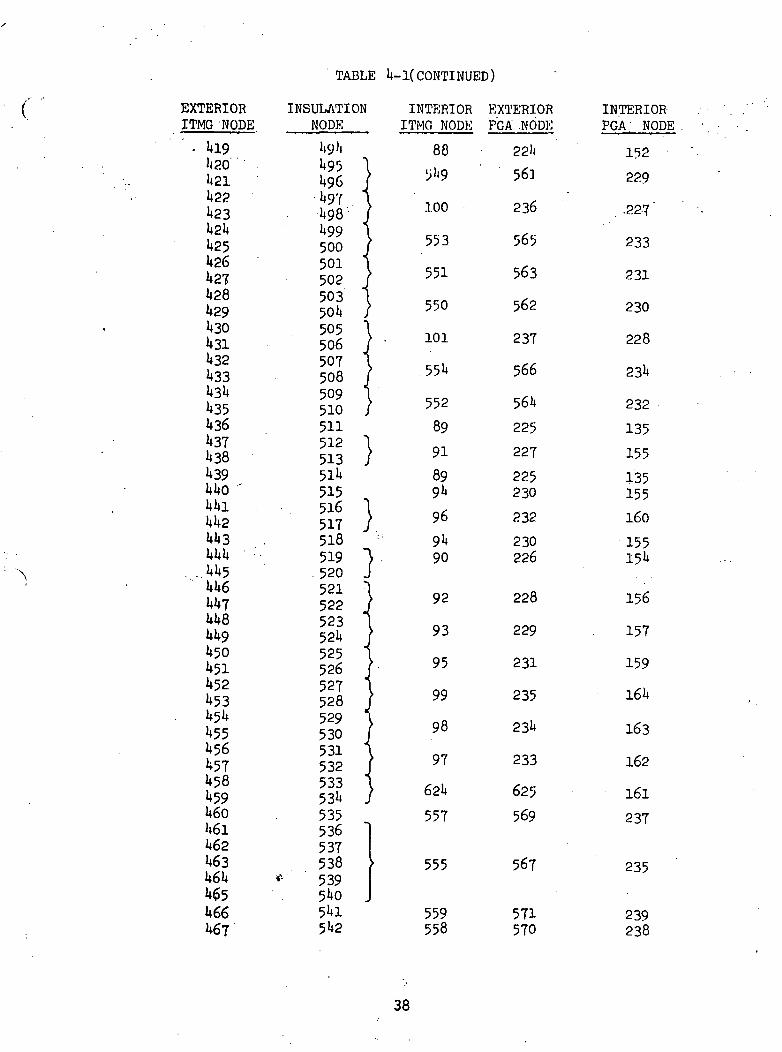
TABLE 1*-1( CONTINUED)
EXTERIORITMG NODE
' . 1*191)201*211*221*231*21*1*251*261*271*281*291*301*311*321*331*31*1*354361*371*38U391*1*0 '1*1*11*1*21*1*31*U1* •1+1*51*1*61 71*1*81*1*91*50U511*521*531*51*1*551*56U571*58**591*601*611*621*631*61*U65U661*67
INSULATION INTERIORNODE ITMG NODE
1*9 Ji 881*95U961*971*98'1*99500501502503501*505506507508509510
$>i9
100
553
551
550
• - 101
551*552
511 89512 } 91513 / 91
5ll* 89515 91*
IS } *518 :: 91*519 ") 90
. 520 J521522523S fc" «^
52l*525526527528529530531532533531*
92
93
95
99
98
97
621*
535 557536537538
* 539540 .
555
51*! 55951*2 558
EXTERIORPGA .NODE
22'l
56.1
236
565
563
562
237
566
561*
225
227
225230
232
230226
228
229
231
235
231*
233
625
569
567
571570
INTERIORPGA NODE
152
229
. .227 '
233
231
230
228
23l*
232
135
155
135155
160
155151*
156
157
159
164
163
162
161
237
235
239238
38
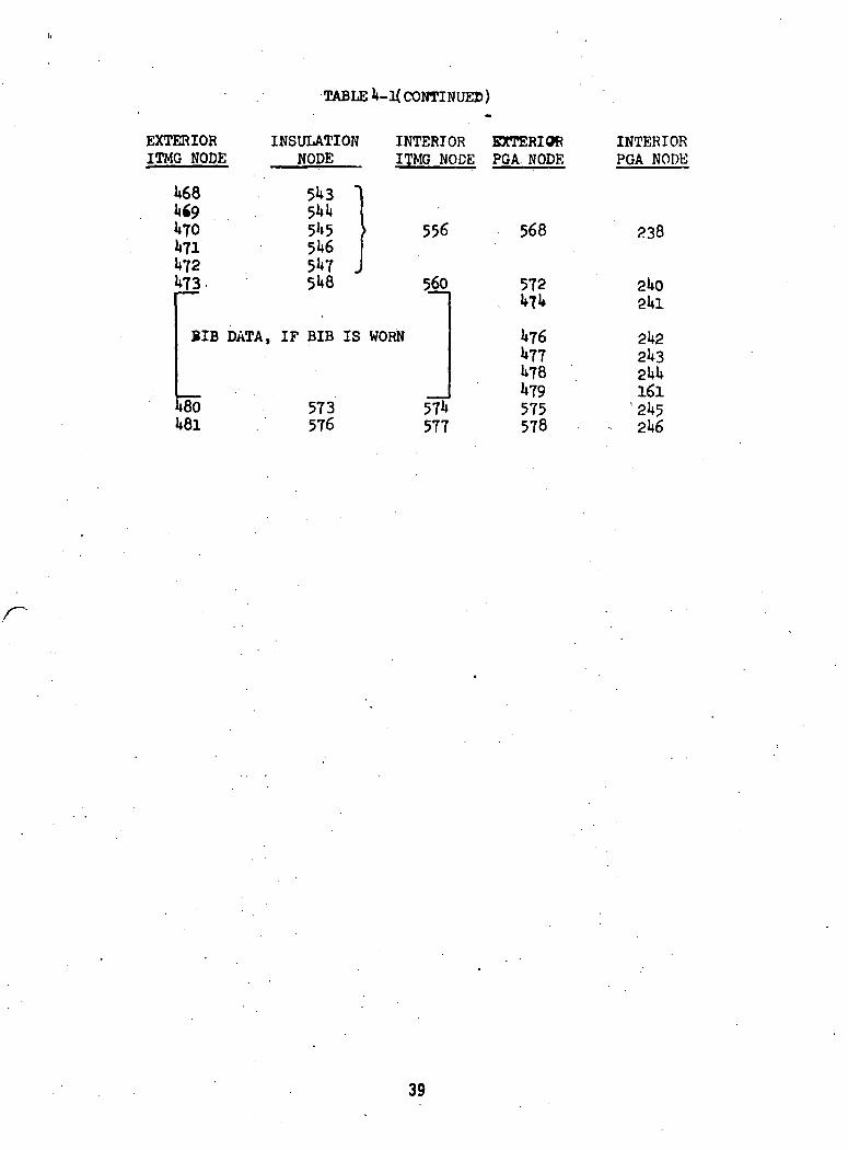
TABLE 1*-1( CONTINUED)
EXTERIORITMG NODE
1*681*691*701*711*721*73.
INSULATIONNODE
5U3
5U551*651*7 J5U8
INTERIOR EXTERIORITMG NODE PGA NODE
556
560
BIB DATA, IF BIB IS WORN
1*801*81
573576
571*577
568
572
1*761*77U781*79575578
INTERIORPGA NODE
238
2UO
2l*22l*3
161'2l*52l*6
39
multilayer buildup were generated by the Lockheed Electronics Corporationunder the direction of the Crew Systems Division - Manned Spacecraft Centerand edited into the baseline thermal model data tape. These conductanceswere based on data obtained from manned and unmanned suit tests conductedby NASA at the Manned Spacecraft Center.
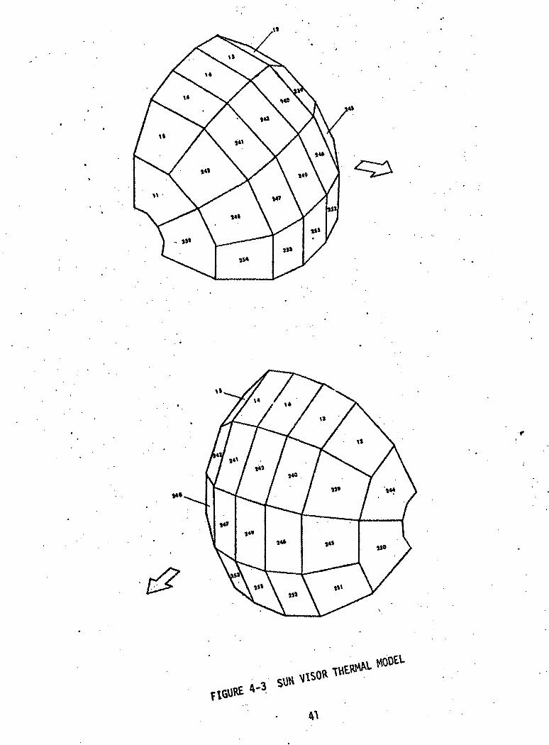
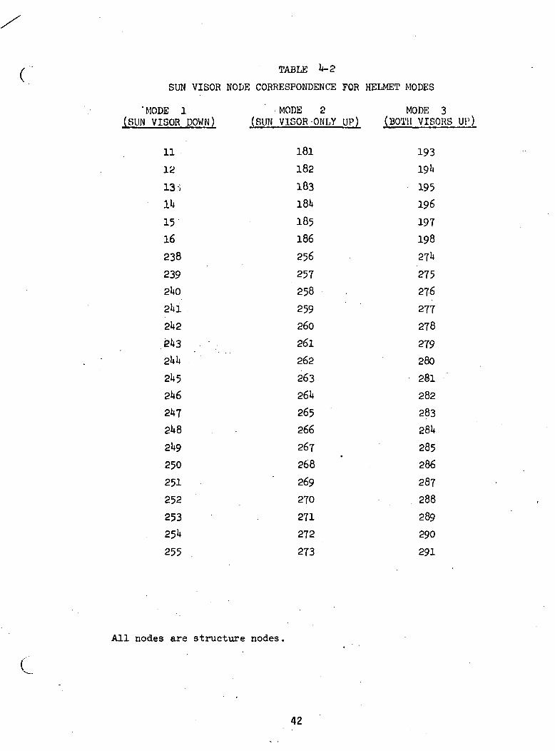
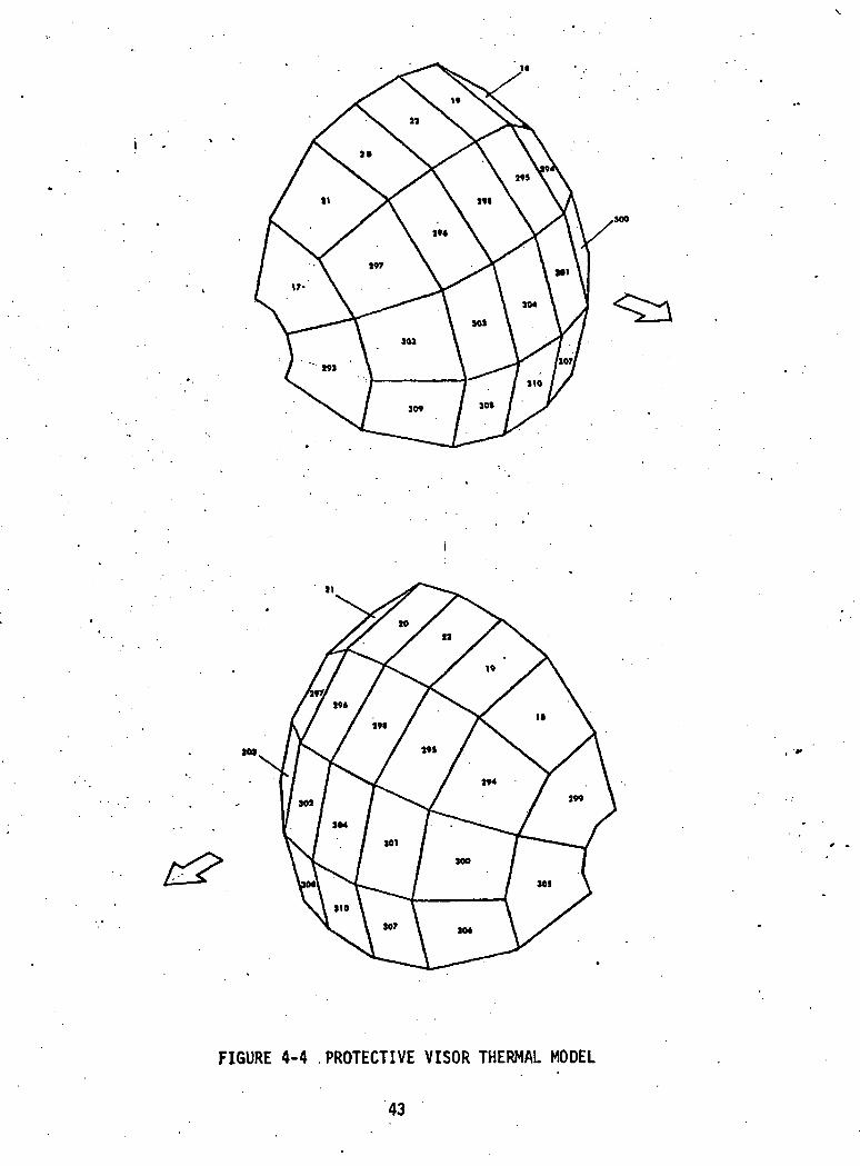
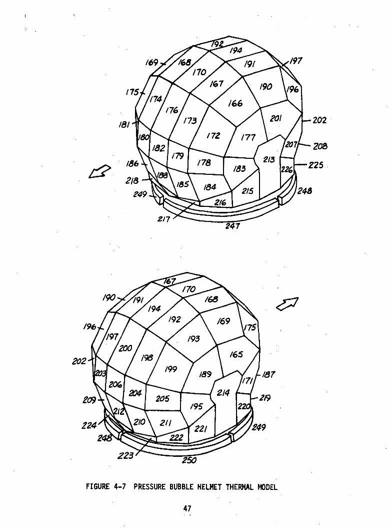
The LEVA thermal model consists of the sun visor, protective visor,pressure bubble, and LEVA shell as presented in Figures 4-3 through 4-7.Tables 4-2 and 4-3. are to be used in conjunction with Figures 4-3 and 4-4respectively in interpreting the thermal model data. The simulator allowsthe user to specify visor configuration changes throughout the mission. Thethree helmet modes illustrated in Figure 3-7 require connections betweennodes peculiar to an individual helmet mode, therefore for the sun visor (SV)and protective visor (PV) there is a set of nodes for each helmet mode. Whenthe helmet is in MODE 1, only the nodes corresponding to this mode for theSV and the PV are analyzed; however the other nodes are updated each iteration.A change to a different helmet mode changes the set of nodes being analyzedand the initial temperatures for the new modes are the last temperatures cal-culated for MODE 1 because of the continuous iteration update. A similar dis-cussion applies when the helmet mode is begun in MODE 2 or MODE 3.
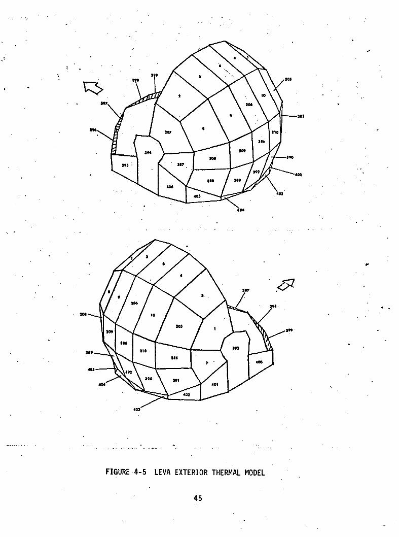
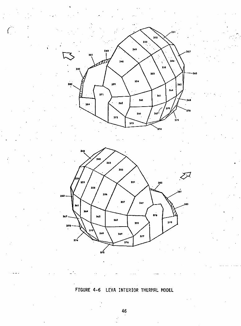
The LEVA shell is divided into two layers thus the node numberingin Figures 4-5 and 4-6. The exterior layer of the LEVA shell thermal modelis the beta cloth cover while the interior layer includes the multilayer in-sulation and the polycarbonate inner shell. There is a single set of shellnodes for the three helmet modes. The surface area nodal breakdown is amodified version of that found in Reference 13. Nodes near the side of thehelmet were increased in area and an additional row of nodes areas were createdalong the vertical centerline maintaining a constant number of nodes.
The pressure bubble is modeled as tube nodes because the insideof the bubble is in contact with the suit oxygen flow. A single set of nodesis used for all three visor configurations and the nodes are analyzed con-tinuously as are the LEVA shell nodes. Two types of connections from thepressure bubble tube nodes must be made a function of the helmet mode. Thefirst is the pressure bubble connection to space when both visors are up andthe second is the connection to the interior layer of the LEVA shell when bothvisors are down. Since both the pressure bubble, the space node, and the LEVA
40
4-3
TABLE
SUN VISOR NODE CORRESPONDENCE FOR HELMET MODES
'MODE 1 MODE 2 MODE 3(SUN VISOR DOWN) (SUN VISOR ONLY UP) (BOTH VISORS UP)
1112
13 :i
11*
15
16238
2392UO
2l*l
2l*2
.81*3
2M» . ' '
2U5
2U6
21* T
2U8
2l»9
250251
25225325U
255
181
182
183
18I»
185186
256
257258
259260
261
262
26326U
265266
267268
269270271272
273
193
19 1*
195196
197198
27l»
275
276
277278
279280
281
282
28328U.
285286
287288
289290
291
All nodes are structure nodes.
C
42
1*
I)
FIGURE 4-4 .PROTECTIVE VISOR THERMAL MODEL
43

TABLE U-3
PROTECTIVE VISOR NOPE CORRESPONDENCE FOR HELMET MOPES
MODE 1 MOPE ?_ MO UK 3( SUN 'VISO-H' DOWN) (RUN VISOR ONLY UP) (BOTH VISORS UP)
17
18
20
21
22
293
291*
295
296
297
298
299300
301
302
303
301*
305306
307
308
309310
187188
189
190
191192
311312
313
31 1*
315316
317318
319320
321
322
323
32U
325
326
327
328
199
200
201
202
203
20 U
329
330
331
332
333
33»»
335336
337338
3393UO
3Ul
3 2
3 3
3M
3i*53U6
All nodes are structure nodes.
44
m
401
40J
sot
FIGURE 4-5 LEVA EXTERIOR THERMAL MODEL
45
r
JJ7
h J6J
3(1
375
160
M7
ISO
173
174
17S
FIGURE 4-6 LEVA INTERIOR THERMAL MODEL
46
n
/90
196
225 250
FIGURE 4-7 PRESSURE BUBBLE HELMET THERMAL MODEL
47
nodes are analyzed continuously, some method of making and breaking theconnections described above is required. The simulator has such a capabilitycalled Time Variant Connections (Section 3.14.5) and it is used to coordinatepressure bubble connections with the visor connections which are determinedby the set of visor nodes analyzed. No intermediate positions of the visorsare allowed; a visor is either all the way up or all the way down. The LEVAhas three sun shades which may be varied by the crewman through an infinitenumber of positions. These sun shades are not modeled in the baseline thermalmodel.
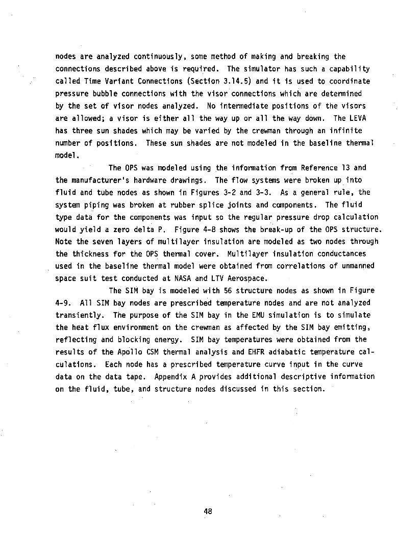
The OPS was modeled using the information from Reference 13 andthe manufacturer's hardware drawings. The flow systems were broken up intofluid and tube nodes as shown in Figures 3-2 and 3-3. As a general rule, thesystem piping was broken at rubber splice joints and components. The fluidtype data for the components was input so the regular pressure drop calculationwould yield a zero delta P. Figure 4-8 shows the break-up of the OPS structure.Note the seven layers of multilayer insulation are modeled as two nodes throughthe thickness for the OPS thermal cover. Multilayer insulation conductancesused in the baseline thermal model were obtained from correlations of unmannedspace suit test conducted at NASA and LTV Aerospace.
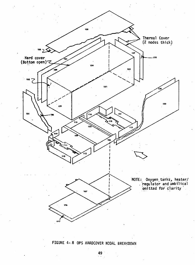
The SIM bay is modeled with 56 structure nodes as shown in Figure4-9. All SIM bay nodes are prescribed temperature nodes and are not analyzedtransiently. The purpose of the SIM bay in the EMU simulation is to simulatethe heat flux environment on the crewman as affected by the SIM bay emitting,reflecting and blocking energy. SIM bay temperatures were obtained from theresults of the Apollo CSM thermal analysis and EHFR adiabatic temperature cal-culations. Each node has a prescribed temperature curve input in the curvedata on the data tape. Appendix A provides additional descriptive informationon the fluid, tube, and structure nodes discussed in this section.
48
Thermal Cover(2 nodes thick)
Hard cover(Bottom open)
NOTE: Oxygen tanks, heater/.'regulator and umbilicalomitted for clarity ' .
FIGURE 4-, 8 OPS HARDCOVER NODAL BREAKDOWN
49
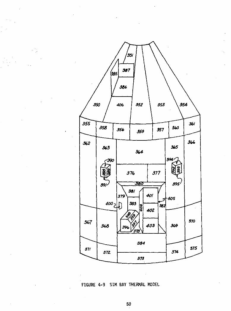
FIGURE 4-9 SIM BAY THERMAL MODEL
50
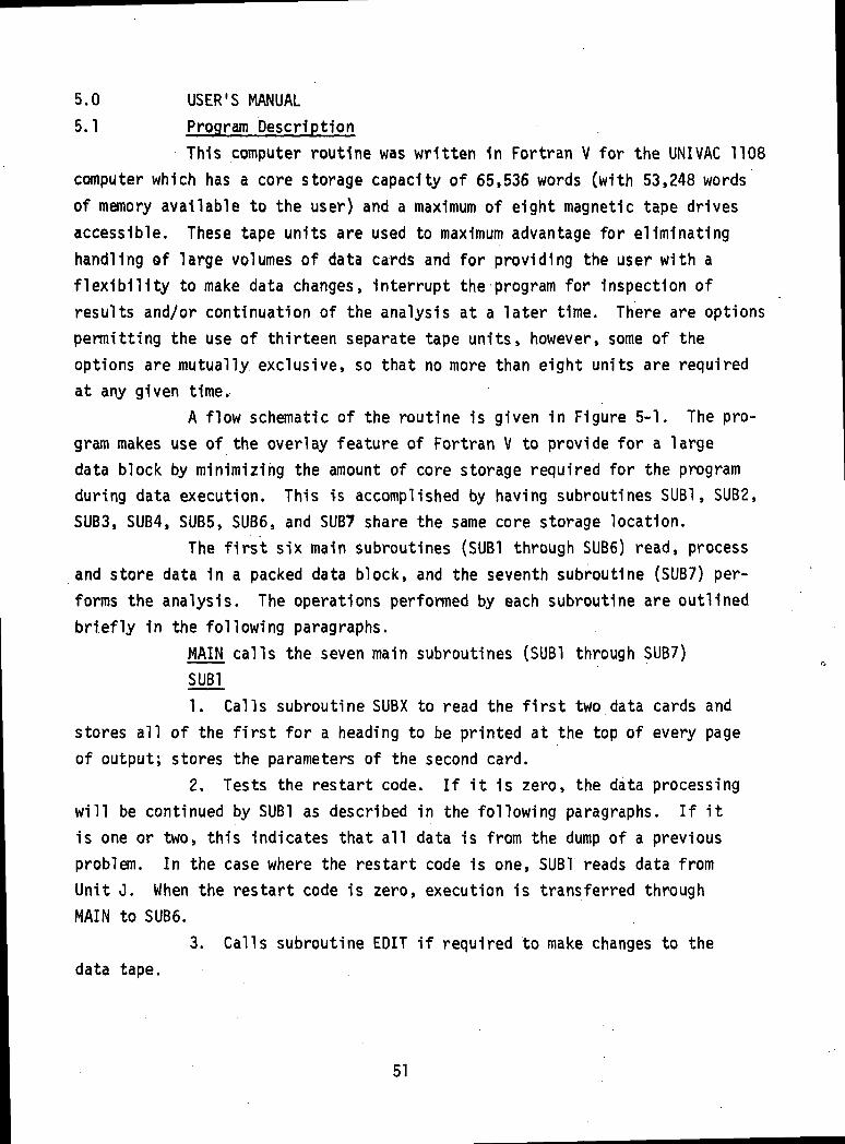
5.0 USER'S MANUAL
5.1 Program Description
This computer routine was written 1n Fortran V for the UNI VAC 1108computer which has a core storage capacity of 65,536 words (with 53,248 wordsof memory available to the user) and a maximum of eight magnetic tape drivesaccessible. These tape units are used to maximum advantage for eliminatinghandling ©f large volumes of data cards and for providing the user with aflexibility to make data changes, Interrupt the program for Inspection ofresults and/or continuation of the analysis at a later time. There are optionspermitting the use of thirteen separate tape units, however, some of theoptions are mutually exclusive, so that no more than eight units are requiredat any given time.
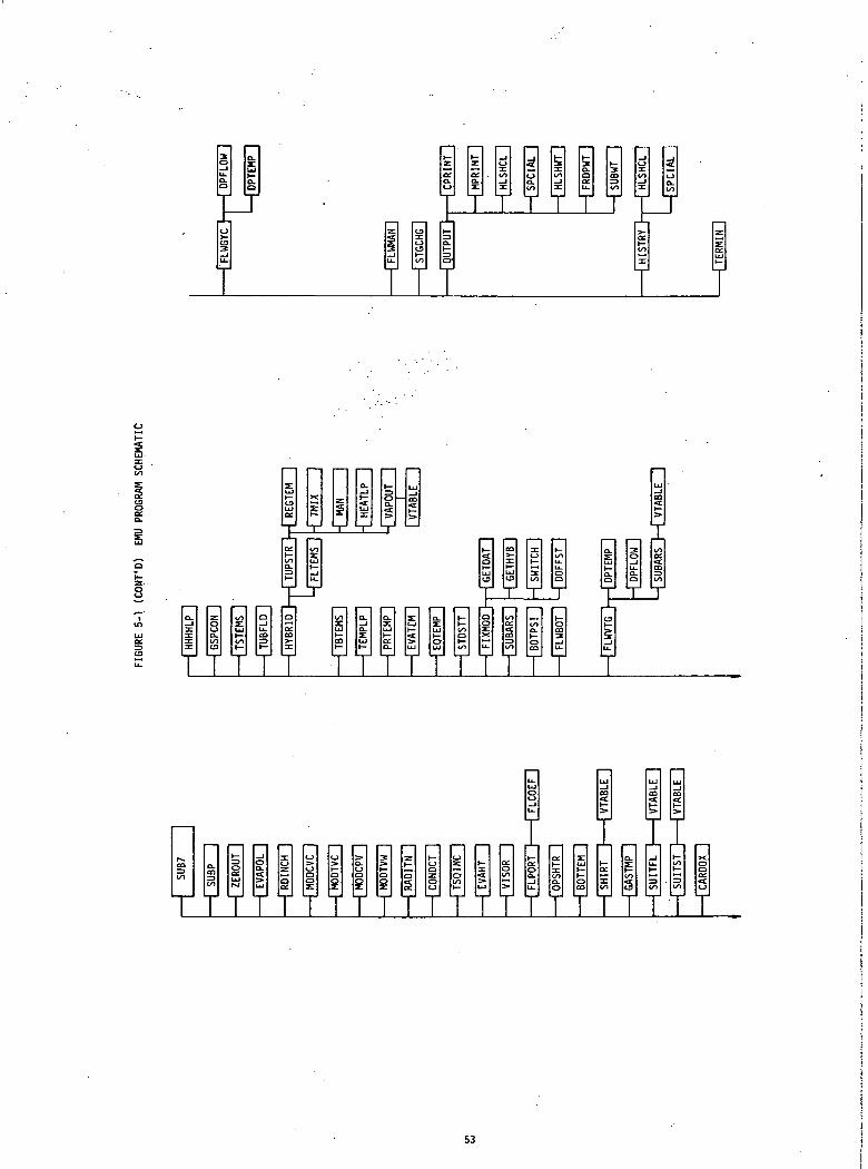
A flow schematic of the routine 1s given 1n Figure 5-1. The pro-gram makes use of the overlay feature of Fortran V to provide for a largedata block by minimizing the amount of core storage required for the programduring data execution. This is accomplished by having subroutines SUB1, SUB2,SUBS, SUB4, SUB5, SUB6, and SUB7 share the same core storage location.
The first six main subroutines (SUB1 through SUBS) read, processand store data in a packed data block, and the seventh subroutine (SUB7) per-forms the analysis. The operations performed by each subroutine are outlinedbriefly in the following paragraphs.
MAIN calls the seven main subroutines (SUB1 through SUB7)SUB!1. Calls subroutine SUBX to read the first two data cards and
stores all of the first for a heading to be printed at the top of every pageof output; stores the parameters of the second card.
2. Tests the restart code. If it is zero, the data processingwill be continued by SUB! as described in the following paragraphs. If itis one or two, this indicates that all data is from the dump of a previousproblem. In the case where the restart code is one, SUBT reads data fromUnit J. When the restart code is zero, execution is transferred throughMAIN to SUB6.
3. Calls subroutine EDIT if required to make changes to thedata tape.
51

i
vhCO
3
1
CJ
iin\
0.OS
§CO
1|Z
J
COosCO
1t—3CO0CO
1_JU-
gs
1eel
1)1
gli|1
Q03AOW
1
Icol|z|o
p!(/) 1
|
o.CJ
to
1
uz
iCO
1si</)]
1
toto_JoCO
1locIcoI >-|z133Ico
|
»—0UJCOOCO
1<*
IO-1o|n:
Izsl1 col
|
>-CO3CO
1O£O.
3
1
O
g3CO
1
>COUJo:
CO
1
Q.z:i iIncj
|
1CJ
1
s 1
rrrYrr
*sCP I
UJl—ILJUJI—iiyi—ii_^
52
T T T T T T
TTTTT TTTTTTTTTT
_ „ I
CO
toCLCO
to
1—
1UJ
_,oo.
UJ
z0zQor
0
ooiu0
O-
isO
>
o
z1—Qs
h-oozoo
0
ot—
t-
5*UJ
o:0COs
u_oLJ_l
h-orgu.
orh-too.0
zUJ
t—0CO
UJ
CO
h-
h-or
CO
o.
CO
3
UJ
CO
u.1-
s
LU
CD
?
|—toI—ZDCO
-T-'
Xgors-t—rTTTTTTTTTTTTTTTTTTTTT
53
4. Calls subroutine SUEHFR which reads and stores the parametersof the third data card, which calls subroutine CENVTP if required to createabsorbed heat flux, prescribed temperature and radiant interchange mode curveson tape Unit E using data on tape Unit 0 and parameter cards 4 and 5.
5. Calls subroutine SUBY to read, check and store the parameterson cards 6 through 20, which calls subroutine CHAPMN to calculate the fractionof the incident solar absorbed by the visors.
6. Calls subroutine SUBZ to read and store the parameters oncards 21 through 26.
7. Writes amount of data space used by parameter card data.8. Returns to MAIN which calls subroutine SUB2.SUB21. Calls subroutine SUBAT to read, check and store the fluid
type data.2. Writes amount of data space used thus far.3. Calls subroutine SUBAL to read, check and store the fluid
lump data.4. Writes amount of data space used thus far.5. Calls subroutine SUBBT to read, check and store the tube
type data.6. Writes amount of data space used thus far.7. Calls subroutine SUBBL to read, check and store the tube
lump data.8. Writes amount of data space used thus far.9. Returns to MAIN which calls SUB3.SUB31. Calls subroutine SUBCT to read, check and store the structure
type data.2. Writes amount of data space used thus far.3. Calls subroutine SUBCL to read, check and store the structure
lump data.4. Writes amount of data space used thus far.5. Calls subroutine SUED to read, check and store local tempera-
ture perturbation data, heat leak data, and heat storage data.6. Writes amount of data space used thus far.
54
7. Calls subroutine SUBE to read, check and store helmet andvisor data, lump Identification data, and configuration-associated node iden-tification data.
8. Writes amount of data space used thus far.9. Calls subroutine SUBF to read, check and store heat flux
curve assignment data and prescribed wall temperature data.10. Writes amount of data space used thus far.11. Calls subroutine SUBG to read, check and store time variant
mass data and time variant connection data.1Z. Writes amount of data space used thus far.13. Returns to MAIN which calls subroutine SUB4.SUB41. Reads, checks and stores all the curve data.2. Calls subroutine BIGSRH to setup curve type number information,
BIGSRH calls subroutine CURSRH to see if a curve is needed.3. Calls subroutine OPERAT to alter code curves by a +. .5 and
converts temperature curves from degrees Fahrenheit to degrees Ranklne.4. Checks for specific heat curve and calls subroutine ENTHPY
to generate an enthalphy curve and a reverse enthalpy curve.5. Calls subroutine BIGCHK to setup calls to CURCHK for curve
types. BIGCHK calls subroutine CURCHK to see if necessary curves have beensupplied.
6. Writes amount of data space used thus far.7. Returns to MAIN which calls SUB5.SUBS1. Calls subroutine SUMISC to define some constant values.2. Calls subroutine SUGRP to setup arrays for the last fluid
lump in each tube, for fluid lumps down a tube for each tube, and for tubelump numbers which enclose the fluid lumps down each tube.
3. Calls subroutine SUMAN to setup the 43 man nodes temperatures,checks and stores enclosed fluid lumps for the man's ten skin and undergarmenttube lumps.
4. Calls subroutine SUCODS to set codes for special fluid, tubeand structure lumps which are not to have temperature calculations.
55
5. Calls subroutine SUSWIT to set logical codes.6. Calls subroutine SUDPFL to setup data for pressure drop
analysis.7. Calls subroutine SUHTVR to setup data for helmet and visor
analysis.8. Calls subroutine MOVVAL to interpolate specific heat, con-
ductivity and time variant mass curves for initial conditions.9. Writes amount of data space used thus far.10. Calls subroutine MOVCOD to move code arrays to configuration
data block.11. Calls subroutine SUCONS to setup data for radiation and
conduction connections between tubes and structure lumps.12. Calls subroutine SUWCP to setup data for weight-specific heat
of tube and structure lumps.13. Calls subroutine SUQINC to setup data for lumps with incident
heat curves.14. Calls subroutine SUMODS to setup codes for classes of lumps
to be analyzed for each EMU configuration mode.15. Calls subroutine SUCLSS to store lumps by classes for EMU
configuration modes. SUCLSS writes amount of data space used thus far.16. Calls subroutine SUHYBR to setup codes for the order of hybrid
calculations for each EMU configuration mode.17. Calls subroutine SUSECT to store fluid lumps to be analyzed
for each EMU configuration mode.18. Writes amount of data space used thus far.19. Calls subroutine SUHOPR to setup data space for various
types of analysis for a particular EMU configuration mode.20. Calls subroutine SUSYSM to setup initial constants and set
diverter valve conditions.21. Calls subroutine SUPRNT to setup temperature print array.22. Calls subroutine SULOAD to zero arrays for initial conditions.23. Calls subroutine SURESV to setup some arrays for use during
iteration loop.24. Calls subroutine CHKLMP to check lumps in certain tubes as
defined under restrictions.
56
25. Calls subroutine CHKCON to check lumps which cannot haveconnections.
26. Writes amount of data space used thus far.27. Returns to MAIN which calls SUB6.SUB61. Stores initial temperatures for the forty-three nodes of
the man.2. Stores area for heat transfer and its reciprocal for the
undergarment tube lumps.3. Test the plot code. If it is not zero, the title and item
count are written on the first record of tape Unit I.4. Test and code for a restart from a previous plot tape. If
It is not zero, temperatures are read from tape unit H for the.time inputas TMPTIM.
5. Returns to MAIN which calls SUB7.SUB71. Test the restart code (ISTART). If it is zero, execution 1s
transferred to FIXMOD; otherwise execution is continued as follows:2. Test the SIM bay prescribed temperature code (NPRTCD). If it
is not zero, then SIM bay prescribed temperature curves (Type 11) read from tapeUnit L.
3. Test the heat flux and prescribed temperature code (NENVTP).If it is not zero, then absorbed heat curves are read from Unit E.
4. Calls subroutine ZEROUT to zero arrays for conductance sum-mation, temperature change and heating rates for fluid, tube and structure1umps.
5. Calls the following subroutines as needed:(a) EVAPOL which interpolates and stores values for absorbed
heat flux (Type 19), prescribed temperature (Type 20) and the generated ra-diant interchange mode curves.
(b) RDINCH which reads radiation connections from UNIT G.(c) MODCVC which calculates connection value for lumps with
conductivity variant connections.(d) MODTVC which calculates connection value for lumps with
time variant connections.
57

(e) MODCPV which calculates weight-specific heat for lumpswith variant specific heat.
(f) MODTVW which calculates weight-specific heat for lumpswith time variant mass.
(g) RADITN which calculates and stores heat rate for lumpswith radiation connections.
(h) CONDCT which calculates and stores heat rate for lumpswith conduction connections.
(i) TSQINC which adds heat rate for lumps with incidentheat curves (Type 9).
(j) EVAHT which adds heat rate for absorbed heat fluxes.(k) VISOR which calculates the amount of heat absorbed
by each helmet and visor lump./
6. Calls subroutine FLPORT which calls subroutine FLCOEF tocalculate heat transfer coefficient for fluid lumps.
7. Calls the following subroutines as needed:(a) OPSHTR which determines whether the oxygen purge system
heater is on or off and adds the heat to appropriate lump if it is on.(b) BOTTEM which calculates temperature for oxygen purge
system and primary oxygen bottles.(c) SHIRT which calculates variables needed when the man is
in a shirtsleeve mode.(d) GASTMP which calculates gas temperature for man fluid
lumps.(e) SUITFL which calculates variables for suit with flowing
gas.(f) SUITST which calculates variables for suit with stagnant
gas.(g) CARDOX which calculates the partial pressure of carbon
dioxide in the helmet.(h) HHHHLP which calculates the heat transfer coefficient
and conductance summation for local temperature perturbation tube lumps.(i) GSPCON which calculates the heat transfer coefficient,
conductance and heat rate for special connection of a fluid lump to a tube lump.
58
(j) TSTEMS which calculates temperature for structure lumpsbeing analyzed.
(k) TUBFLD which calculates conductance and heat rates fortube and fluid lumps being analyzed.
8. Calls subroutine HYBRID which determines fluid lump temperaturesand lumps requiring special calculation using the following subroutines:
(a) TUPSTR which determines the upstream temperature for thelumps using the following subroutines:
(1) REGTEM which calculates the upstream temperaturefor the oxygen purge system and primary oxygen system regulators.
(2) TMIX which calculates a temperature when two ormore fluids are mixed together.
(3) MAN which calculates the man temperatures.(4) HEATLP which calculates heat rate for local per-
turbation tube lumps.(5) VAPOUT which calculates water vapor added to the
gas by the man, and specific humidity out of the suit.(b.) FLTEMS which calculates temperatures of fluid lump being
analyzed.9. Calls the following subroutines as needed:
(a) TBTEMS which calculates temperatures of tube lumps beinganalyzed.
(b) TEMPLP which calculates temperatures for local perturba-tion fluid and tube lumps.
(c) PRTEMP which interpolates prescribed wall temperaturecurves type 10 and sets temperatures of appropriate lumps.
(d) EVATEM which sets the temperature of lumps with pre-scribed temperature curves, type 20.
(e) EQTEMP which sets temperatures of unanalyzed helmet andvisor lumps to temperature of analyzed lumps.
(f) STDSST which checks man's sweat or shiver rate forstabilization and temperature difference against steady state criterion.
10. FIXMOD which set variables for this iteration depending onthe helmet and EMU configuration modes. It calls subroutines GETDAT and
59
GETHYB to store lumps to be analyzed in this iteration, DOFFST to doff thesuit and SWITCH which determines logical variables which are used by SUB7to determine which subroutines will be called.
11. Calls the following subroutines as needed:(a) SUBARS which sets inlet temperature, flowrate and
pressure into the suit when the ARS is activated.(b) BOTPSI which determines pressure of the oxygen purge
system and primary oxygen system bottles.(c) FLWBOT which sets flowrate in oxygen purge system tubes
7 and 8 and primary oxygen system tubes 4 and 6.(d) FLWVTG which sets flowrate in oxygen tubes. FLWVTG calls
DPTEMP, DPFLOW and SUBARS which calculate pressure drop in the flow tubes.(e) FLWGYC which sets flowrate in tube 4. FLWGYC calls
DTEMP and DPFLOW which calculate pressure drop in the tubes mentioned above.(f) FLWMAN which sets flowrate in the man oxygen tubes.(g) STGCHG which calculates water vapor of suit gas nodes
when the suit has no flow.12. Calls the following when it is time to print:
(a) OUTPUT which writes headings.(b) CPRINT which writes consumable data.(c) MPRINT which writes man temperatures and man associated
quantities.(d) HLSHCL which calculates heat leak and heat storage.(e) SPCIAL which calculates solar energy transmitted through
the visors and added to the first heat leak group.(f) HLSHWT which writes heat leak and heat storage data.(g) FRDPWT which writes flowrates and pressure drops,(h) SUBWT which converts a block of temperatures from
Rankine to Fahrenheit, writes the temperatures, and converts them back toRankine,
60
(i) HISTRY which writes history tape on Unit K.(j) TERMIN which writes a message when the run is terminated.
13. Test the computer time usage and ends the run if requestedtime 1s exceeded. .
14. Writes the entire data block and the variable block on tapeUnit I, 1f the run 1s ended before completion or if the dump option is used,so that the problem can be restarted at a later time.Miscellaneous
(1) Function BIPOL - does table look-up and straight lineInterpolation on bi-variant curves.
(2) Function Pol - does table look-up and straight line inter-polation.
(3) Subroutine SPCTIM - checks data space required against dataspace available and writes amount of data used.
(4) Subroutine SUBP - starts a new page of output and writesparameter card one as a heading.
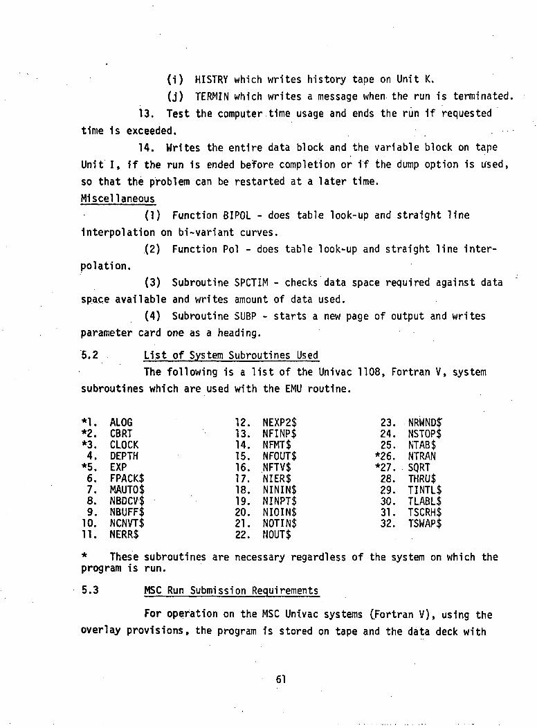
5.2 List of System Subroutines UsedThe following is a list of the Univac 1108, Fortran V, system
subroutines which are used with the EMU routine.
*1. ALOG*2. CBRT*3. CLOCK4. DEPTH*5. EXP6. FPACK$7. MAUTO$8. NBDCV$9. NBUFF$10. NCNVT$11. NERR$
12. NEXP2$13. NFINP$14. NFMT$15. NFOUT$16. NFTV$17. NIER$18. NININ$19. NINPT$20. NIOIN$21. NOTIN$22. NOUT$
23. NRWNDIT24. NSTOP$25. NTAB$
*26. NTRAN*27. SQRT28. THRU$29. TINTL$30. TLABL$31. TSCRH$32. TSWAP$
* These subroutines are necessary regardless of the system on which theprogram is run.
5.3 MSC Run Submission Requirements
For operation on the MSC Univac systems (Fortran V), using theoverlay provisions, the program is stored on tape and the data deck with
61
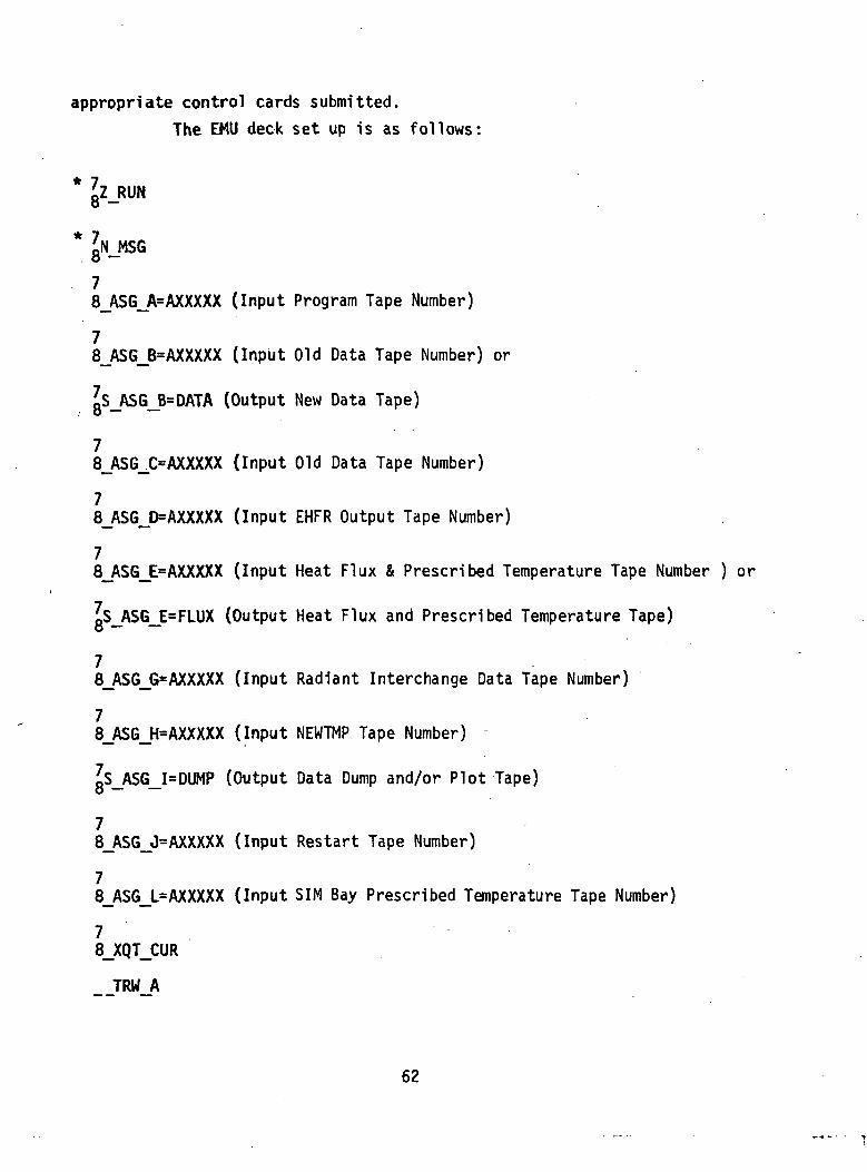
appropriate control cards submitted.The EMU deck set up is as follows:
* aZ-RUN
* JN MSG. o —
78_ASG_A=AXXXXX (Input Program Tape Number)
78_ASG_B=AXXXXX (Input Old Data Tape Number) or
gS_ASG_B=DATA (Output New Data Tape)
78_ASG_C=AXXXXX (Input Old Data Tape Number)
78_ASG_D=AXXXXX (Input EHFR Output Tape Number)
78_ASG_E=AXXXXX (Input Heat Flux & Prescribed Temperature Tape Number ) or
Is ASG E=FLUX (Output Heat Flux and Prescribed Temperature Tape)o — —
78_ASG_G=AXXXXX (Input Radiant Interchange Data Tape Number)
78_ASG_H=AXXXXX (Input NEWTMP Tape Number) -
oS ASG I=DUMP (Output Data Dump and/or Plot Tape)o — —
78_ASG_J=AXXXXX (Input Restart Tape Number)
78_ASG_L=AXXXXX (Input SIM Bay Prescribed Temperature Tape Number)
78_XQT_CUR
TRW A
62
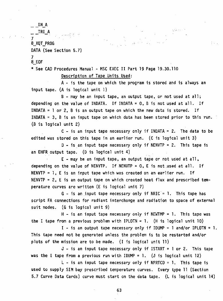
__TRI_A '•••"'"7 " •''•"" ' '8_XQT_PROG . . : - • • . . . .
DATA (See Section 5.7)78_EOF* See CAD Procedures Manual - MSC EXEC II Part 19 Page 19.30.110
Description of Tape Units Used;A - Is the tape on which the program is stored and is always an
input tape. (A is logical unit 1)B - may be an input tape, an output tape, or not used at all;
depending on the value of INDATA. If INDATA = 0, B is not used at all. IfINDATA = 1 or 2, B is an output tape on which the new data is stored. IfINDATA = 3, B is an input tape on which data has been stored prior to this run.(B is logical unit 2)
C - is an input tape necessary only if INDATA = 2. The data to beedited was stored on this tape in an earlier run. (C is logical unit 3)
D - is an input tape necessary only if NENVTP = 2. This tape isan EHFR output tape. (D is logical unit 4)
E - may be an input tape, an output tape or not used at all*depending on the value of NENVTP. If NENVTP = 0, E is not .used at all. IfNENVTP = 1, E is an input tape which was created on an earlier run. IfNENVTP = 2, E is an output tape on which created heat flux and prescribed tem-perature curves are written (E is logical unit 7)
G - is an input tape necessary only if NRIC = 1. This tape hasscript FA connections for radiant interchange and radiation to space of externalsuit nodes. (G is logical unit 9)
H - is an input tape necessary only if NEWTMP = 1. This tape wasthe I tape from a previous problem with IPLOTN =1. (H is logical unit 10)
I - is an output tape necessary only if IDUMP = 1 and/or IPLOTN = 1.This tape need not be generated unless the problem is to be restarted and/orplots of the mission are to be made. (I is logical unit 11)
J - is an input tape necessary only if ISTART = 1 or 2. This tapewas the I tape from a previous run with IDUMP =1. (J is logical unit 12)
L - is an input tape necessary only if NPRTCD = 1. This tape isused to supply SIM bay prescribed temperature curves. Every type 11 (Section5.7 Curve Data Cards) curve must start on the data tape. (L is logical unit 14)
63
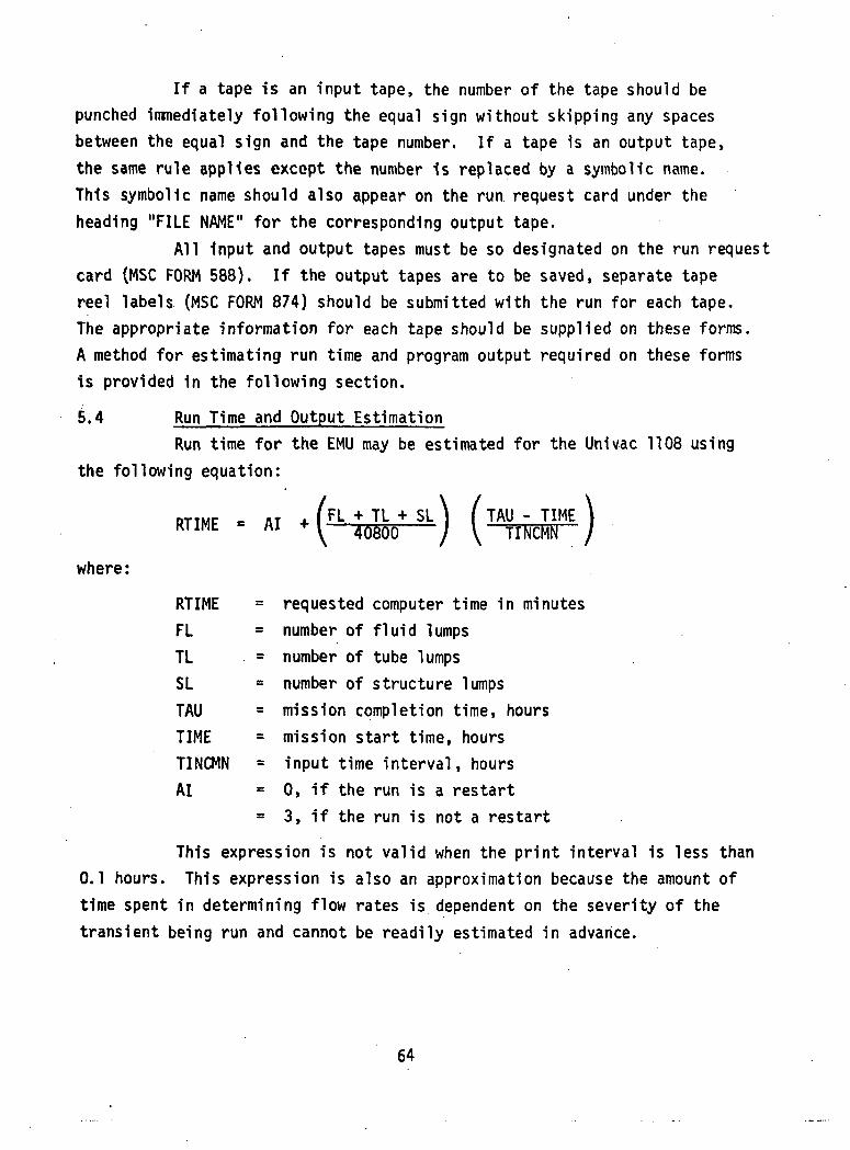
If a tape is an input tape, the number of the tape should bepunched immediately following the equal sign without skipping any spacesbetween the equal sign and the tape number. If a tape is an output tape,the same rule applies except the number is replaced by a symbolic name.This symbolic name should also appear on the run request card under theheading "FILE NAME" for the corresponding output tape.
All Input and output tapes must be so designated on the run requestcard (MSC FORM 588). If the output tapes are to be saved, separate tapereel labels (MSC FORM 874) should be submitted with the run for each tape.The appropriate information for each tape should be supplied on these forms.A method for estimating run time and program output required on these formsis provided in the following section.
5.4 Run Time and Output EstimationRun time for the EMU may be estimated for the Univac 1108 using
the following equation:
RTIME = AI
where:
(FL + TL + SL\ ( TAU - TIME \\ 4 1 ) 8 0 0 / \ TINCMN /
RTIME = requested computer time 1n minutesFL = number of fluid lumpsTL = number of tube lumpsSL = number of structure lumpsTAU = mission completion time, hoursTIME = mission start time, hoursTINCMN = input time interval, hoursAI = 0, if the run is a restart
= 3, if the run is not a restart
This expression is not valid when the print interval is less than0.1 hours. This expression is also an approximation because the amount oftime spent in determining flow rates is dependent on the severity of thetransient being run and cannot be readily estimated in advance.
64
Output from EMU may be estimated using the following equation:
NPO « 1 8 + 3 TApE[YAJJME + 23 AI + 70 BI
where:
NPO = number of pages of outputTAU = mission completion timeTIME = mission start timeDELTAU = print intervalAI =0, if the run is restart
= 1, if the run is not a restartBI = 0, if the data tape is not edited
= 1, if the data tape is edited
5.5 RestrictionsProgramming, analytical, and core storage space restrictions
applicable to the EMU are outlined in the following paragraphs.5.5.1 Programming
Some of the programming restrictions are described in other partsof the report and are listed here to emphasize their importance.
A. A fluid lump may be enclosed by more than one tube lump,but it must be enclosed by at least one.
B. When setting up the fluid lump data, care must be exercisedto insure that upstream lumps are set up properly. Datashould be listed so that it is possible to go from the lastlump in the tube to the first lump in that tube simply byfollowing the upstream lump numbers. All fluid lumps in thetube should be covered in this search.
C. When conduction data is set-up, the second conductance valuemay be zero, but the first should never be in order to savecore storage space.
D. tubes TzTTsTTTTTl, 14, 18."15,"19, 16 and 20 contain thevent gas flow over the trunk, right arm, right leg, head,
65
right hand, right foot, left arm, left leg, left hand andleft foot respectively and must contain one and only onefluid lump, Each preceding fluid lump must bi enclosedby at least two tube lumps one of which must be the corres-ponding skin tube lump number. Additional tube lumps, en-closing the suit fluid lumps and representing the insidesuit wall, are required by the program.
E. Tube 9 must contain at least two fluid lumps.F. The structure lump of oxygen in the OPS bottle on left side
and right side and the tube lump surrounding the first lumpin tube 9 must not have any connections.
G. If a lump has a prescribed temperature, the temperature isprescribed for the entire problem according to the curvedata input.
5.5.2 AnalyticalIn addition to the analytical restrictions for any finite dif-
ference approximation to differential equations, the user of the EMU shouldalso be aware of the following:
A. The EMU has special equations or curves for computing thepressure drop of various components. In order to computea pressure drop of zero for the fluid lump which representsthe component, a wetted perimeter of zero must be specifiedfor the fluid lump. However, the specifying of a wettedperimeter of zero causes the calculation of a zero heattransfer coefficient for the fluid lump. Therefore, if aheat transfer coefficient other than zero is needed, itmust be specified on a curve as a function of flow rate.
B. The EMU automatically determines for the lumps on the visors,the amount of incident solar and incident infrared radiationabsorbed as a function of visor position. The visor nodeconnections are made and broken automatically according tovisor position. The pressure bubble lumps connected tothe LEVA shell lumps must be done manually by use of lumpswith time variant properties. The time variant curve must beconsistent with the helmet mode curve which is a function ofmission time.
66
5.5.3 Core Storage SpaceThe computer program requires approximately 8000 core locations.
In addition, a blank common block of 40,980 is allocated for storing inputand calculated data. The largest part of the common block is assigned to anarray called DATA. Basically the size of this array is determined by the sizeof core and the size of the SUB7 link. For operation on the Univac 1108 thedimensioned size of DATA is 40,000 locations. The DATA array is divided intothree sections: transient, permanent and temporary. The transient sectionhas two blocks, iteration and configuration, which share the 14,000 locationsavailable. Only one block is stored in core at a time, while the other isstored on a drum. The iteration block occupies core all the time except whenan EMU configuration change takes place and the configuration block is in coreto make necessary changes to the permanent section. The permanent and temporarysections have variable length which cannot exceed 26,000 locations. Thesestorage values are allocated as shown in the following paragraph.5.6 Program Options5.6.1 Plot Tape
A "1" punch in column 68 of parameter card 2 will cause the gen-eration of a plot tape. This tape will have all of the fluid, tube, andstructure lump temperatures, plus other items indicated below, recorded on itunder control of the plot interval given on Card 2. The plot tape is gener-ated on tape UNIT I. Setup cards are required when the program is submittedto cause the tape to be mounted as discussed in Section 5.3. Also, the com-puter request card must indicate that there is to be an output tape on UNIT I.
The format of the plot tape is:Record No. 1Title (from title card, 12A6), 0, 0, 0, 0, 0, 0, 0, 0,0, 0, 0, 0, 2, 2, 2, 1, 1, 1, 7, 8, 43, number of groupsof heat leak calculations, number of groups of heat storagecalculations, number of flowrates, number of pressure drops,number of fluid temperatures, number of tube temperatures,number of structure temperatures.
67
Record No. 2Time, crewman stored heat, partial pressure of C02 inhelmet, dewpoint temperature in helmet, suit inlet specifichumidity, suit outlet specific humidity, pressure in OPS'bottles, X, X, X, X, crewman sensible heat loss, crewmanevaporation heat loss, crewman latent heat loss, crewmanstorage rate, crewman shiver rate, crewman metabolic rate,oxygen 1n OPS bottles, X, X, X, X, X, X, unremoved sweaton crewman, crewman temperatures, flowrates, pressure drops,fluid lump temperatures, tube lump temperatures, andstructure lump temperatures.Record No. 3Time, etc.The last record has a negative time to indicate end of output.
This record need not be included in the plot since the values printed outare identical to those on the previous record.5.6.2 Restart
Requested Dump for RestartingAny problem can be dumped and restarted at a later time. This is
achieved by punching a "1" in column 70 on parameter card 2. This option isuseful in data checkout in that a problem can be submitted for a short tran-sient time, and, after examination of the results, restarted for a longertransient time. The computer request card must specify that the output tapeis expected, and the proper set-up card must be included in the deck.
Automatic Dump for RestartingIf a problem does not attain the specified mission transient time
within the requested computer time, the problem is dumped and may be restartedlater. This occurs whether there is a "1" in column 70 on parameter card 2or not. The computer request card must specify that an output tape is expectedor the dump will be lost; a save tape label must also be provided.
Restart ProcedureThe procedure for restarting a problem which has been dumped is:(1) Fill out the computer request card as in an initial run,
except specify the previously dumped tape as an input tapeon Unit J.
68
(2) If on the initial run, an EHFR tape was input on Unit D,the output tape created on Unit E is specified as aninput tape on restart. An EHFR tape cannot be useddirectly on restart.
(3) Submit only the first two of the data cards (that is,parameter cards 1 and 2) with a "1" punch in column 60on Card 2 to indicate that data is to be read from arestart tape.
5.6.3 EDITThe large number of data cards required for problems run on this
routine presents three problems: (1) increased probability of operator and/orcard reader error, (2) increased probability of a card reader jam, and (3)significant extra time required to read in data from the card reader whenproblem (2) occurs. For these reasons a routine was developed (Reference 14)for reader input data from tape with the capability for modifying the dataon read-in.
The EDIT routine is called by parameter INDATA input on columns61 and 62 on parameter card 2. Possible inputs are:
(1) INDATA = 0, All data is supplied on cards.(2) INDATA =1, All data is supplied on cards and the card
images are written on tape on Unit B. (Should be specifiedas an output tape on job card).
(3) INDATA =2, Use data input on tape on Unit C with desiredchanges on cards to write a new data tape on Unit B. (C isinput tape and B is output tape)
(4) INDATA =3, Use the data read in from Unit B without change.Parameter cards 1 and 2 are read in from cards. (B is inputtape)
If INDATA = <0, the card images are punched as they are written onUnit B.
When INDATA = 2, deck set-up consists of parameter cards 1 and 2,the EDIT control cards (described below), and the new data cards (with thesame format as the cards being replaced).
69
The EDIT control cards, used only when INDATA has a value of+. 2 are:
COLUMN FORMAT NAME DESCRIPTION1 Al ID * 1n column 1 Identifies the card as an
EDIT control card6-15 HO K3 Card number of first card to be removed
if K3 is positive and K4 > 0. If K3is negative, K3 is the card number ofthe card for which a merge correctionwill be performed. If K4 is blankor zero, cards change cards betweenthis card and the next EDIT Controlcard will be added immediately fol-lowing card K3.
16-25 110 K4 Card number of last card to be removedprior to inserting the change cardsin the data. If K3 is negative, K4is ignored.
The Unit C tape is not altered in any way should there be errorsin the edit deck which cause fatal errors in the LTV program. It is theresponsibility of the user to maintain extra copies of the data tape and/oran up-to-date card deck.5.6.4 Imposed Node Temperature History
It is possible to impose a temperature history on structure nodesfor the duration of ,the problem. The temperature history is called a pre-scribed wall temperature and data preparation is given in Section 5.7.12.5.6.5 Heat Flux and Prescribed Temperature Data From EHFR
The Environmental Heat Flux Routine (EHFR) outputs on a tape,incident heat in two wavelength bands (solar and infrared) for each helmetand visor node of its geometrical model of the EMU. Absorbed heat for eachremaining node and a contact temperature is also output on the tape. Thistape is used as input to the EMU simulator on tape Unit D when NENVTP = 2,the EMU simulator reads data from Unit D and creates on Unit E curves ofabsorbed heat, incident solar heat, incident infrared heat, and contact
70
temperature as specified on parameter cards 4 and 5. The incident solar andincident infrared heat curves are assigned in the Helmet and Visor Data(Section 5.7.8) while the absorbed heat and contact temperature curves areassigned 1n the Curve Assignment Data (Section 5.7.11). The tape createdon Unit E on one run can be used on other runs as an input tape by specifyingNENVTP = 1. The user can, by specifying NENVTP = 0, input curves requestedon parameter card 3 in the Curve Data (Section 5.7.15) as type 19 and type20 curves. Parameter cards 4 and 5 must be omitted and tapes are not specifiedfor Unit D and Unit E. If NENVTP = 0, and NRIC = 1, the user must supply atype 21 (radiant interchange mode) curve. This curve determines the set ofradiant interchange connection values to be used from Unit G as a function oftime. The connection values should correspond to the variation in EHFR heatflux which is a function of the EMU geometric configuration.
To restart a run which uses an EHFR tape as input on Unit D, atape must have been created on Unit E and saved for restart. The tape generatedon Unit E becomes an input tape read from the same unit. Unit D cannot beused on restart. (Section 5.6.2)
71
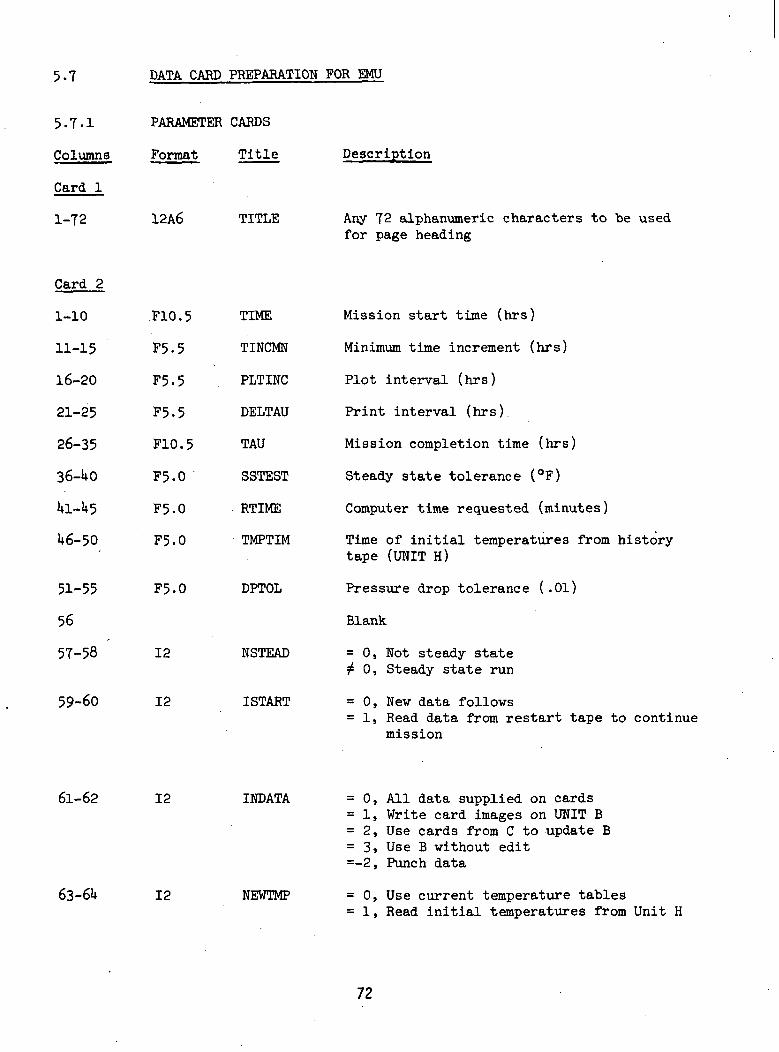
5.7 DATA CARD PREPARATION FOR EMU
5. T.I
Columns.
Card 1
1-72
Card 2
1-10
11-15
16-20
21-25
26-35
36-UO
Ul-l*5
U6-50
51-55
56
57-58
PARAMETER
Format
12A6
.F10.5
P5-5
F5.5
F5.5
F10.5
F5.0
F5.0
F5.0
F5.0
12
CARDS
Title
TITLE
TIME
TINCMN
PLTINC
DELTAU
TAU
SSTEST
RTIME
TMPTIM
DPTOL
NSTEAD
59-60 12 ISTART
Description
Any 72 alphanumeric characters to be usedfor page heading
Mission start time (hrs)
Minimum time increment (hrs)
Plot interval (hrs)
Print interval (hrs).
Mission completion time (hrs)
Steady state tolerance (°F)
Computer time requested (minutes)
Time of initial temperatures from historytape (UNIT H)
Pressure drop tolerance (.01)
Blank
= 0, Not steady state2 0, Steady state run
= 0, New data follows= 1, Read data from restart tape to continue
mission
61-62
63-6U
12
12
INDATA
NEWTMP
0, All data supplied on cards1, Write card images on UNIT B2, Use cards from C to update B3, Use B without edit-2, Punch data
0, Use current temperature tables1, Read initial temperatures from Unit H
72

Columns Format Title Description
Card 2 (Continued)
65-66 12 .-. NPRTCD
67-68
69-70
12
12
IPLOTN
IDUMP
0, Use current SIMBAY prescribed temperaturetables
1, SIMBAY prescribed temperature tables :supplied by UNIT L
0, No temperature history1, Write temperature history on UNIT I
0, No dump tape to be written1, Dump data on UNIT I when either TAU
or RTIME is exceeded
Card 3
1-5
6-10
11-15
16-20
21-25
26-30
15
15
15
15
15
15
NTFL
NTML
NSL
NIHEVA
NPTEVA
NENVTP
31-35 15 URIC
Total number of fluid lumps
Total number of tube lumps
Total number of structure lumps
Number of heat flux curves to be createdfrom EHFR output or supplied in curve data.If none, enter zero.
Number of prescribed temperatures historycurves to be created from EHFR output orsupplied in curve data. If none, enter zero.
Code for heat flux curves, type 19> andprescribed temperature curves, type 20,= 0, Curves supplied in curve data= 1, Heat flux and prescribed temperature
curves read from UNIT E,= 2, Heat flux and prescribed temperature
curves created on UNIT E from EHFRoutput on UNIT D
= 0, No radiant interchange tape= 1, Read radiant interchange tape on UNIT G.
Card
1-5
6-10
15
15
NUM
NF
Curve number assigned to this group ofcombined heat fluxes (or temperature histor-ies)
Number of heat fluxes (or temperature his-tories) from EHFR composing this group
73
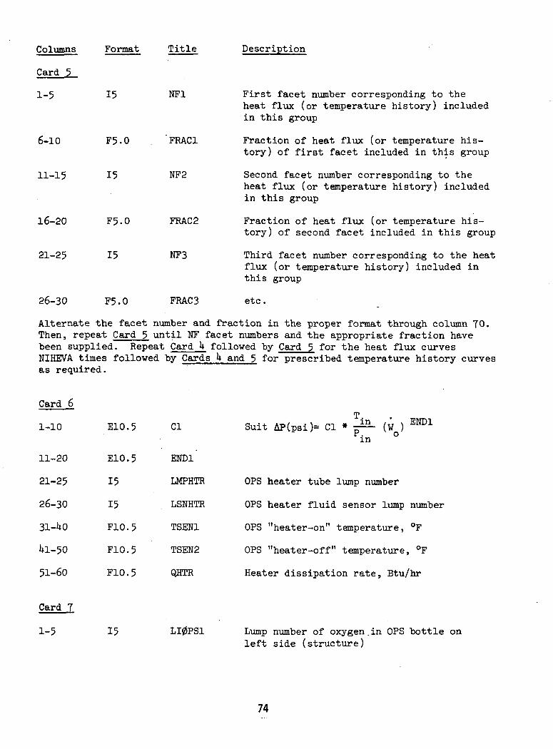
Columns Format Title Description
Card 5
1-5
6-10
11-15
16-20
21-25
26-30
15
F5.0
15
F5.0
15
F5.0
NF1
FRAC1
NF2
FRAG 2
NFS
FRAC3
First facet number corresponding to theheat flux (or temperature history) includedin this group
Fraction of heat flux (or temperature his-tory) of first facet included in this group
Second facet number corresponding to theheat flux (or temperature history) includedin this group
Fraction of heat flux (or temperature his-tory) of second facet included in this group
Third facet number corresponding to the heatflux (or temperature history) included inthis group
etc.
Alternate the facet number and fraction in the proper format through column TO.Then, repeat Card 5 until NF facet numbers and the appropriate fraction havebeen supplied. Repeat Card k followedNIHEVA times followedas required.
Card 6
1-10
11-20
21-25
26-30
31-1*0
Ul-50
51-60
Card 7
1-5
E10.5
E10.5
15
15
F10.5
F10.5
F10.5
15
by Cards U and 5
Cl Su
END1
LMPHTR OP!
LSNHTR OP!
TSEN1 OPi
TSEN2 OP!
QHTR Hei
LI0PS1 Lui
Suit AP(psi)= Cl *n
(W ) END1
OPS heater tube lump number
OPS heater fluid sensor lump number
OPS "heater-on" temperature, °F
OPS "heater-off" temperature, °F
Heater dissipation rate, Btu/hr
Lump number of oxygen.in OPS bottle onleft side (structure)
74
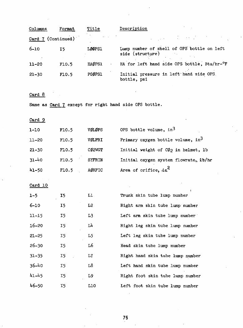
Columns Format Title Description
Card 7
6-10
11-20
21-30
Card 8
Same as
Card 9
1-10
11-20
21-30
1*1-50
(Continued)
15
F10.'5
F10.5
Card 7 except
F10.5
F10.5
F10.5
F10.5
F10.5
L00PS1
HA0PS1
PG0PS1
for right
V0L0PS
V0LPRI
C02WGT
SYFRIN
A0RFIC
Lump number of shell of OPS bottle on leftside (structure)
HA for left hand side OPS bottle, Btu/hr-°F
Initial pressure in leffhand -side OPS.bottle, psi
hand side OPS bottle.
OPS bottle volume, in3
Primary oxygen bottle volume, in'
Initial weight of C02 in helmet, Ib
Initial oxygen system flowrate,, Ib/hr
2Area of orifice, /in
Card 10
1-5
6-10
11-15
16-20
21-25
26-30
31-35
36-UO
U1-U5
1*6-50
15
15
15
15
15
15
15 .
15
15
15
LI
L2
L3
Lit
L5
L6
L7
•L8
L9
L10
t
Trunk skin tube lump number
Right arm skin tube lump number
Left arm skin tube lump number
Right leg skin tube lump number
Left leg skin tube lump number
Head skin tube lump number
Right hand skin tube lump number
Left hand skin tube lump number
Right foot skin tube lump number
Left foot skin tube lump number
75
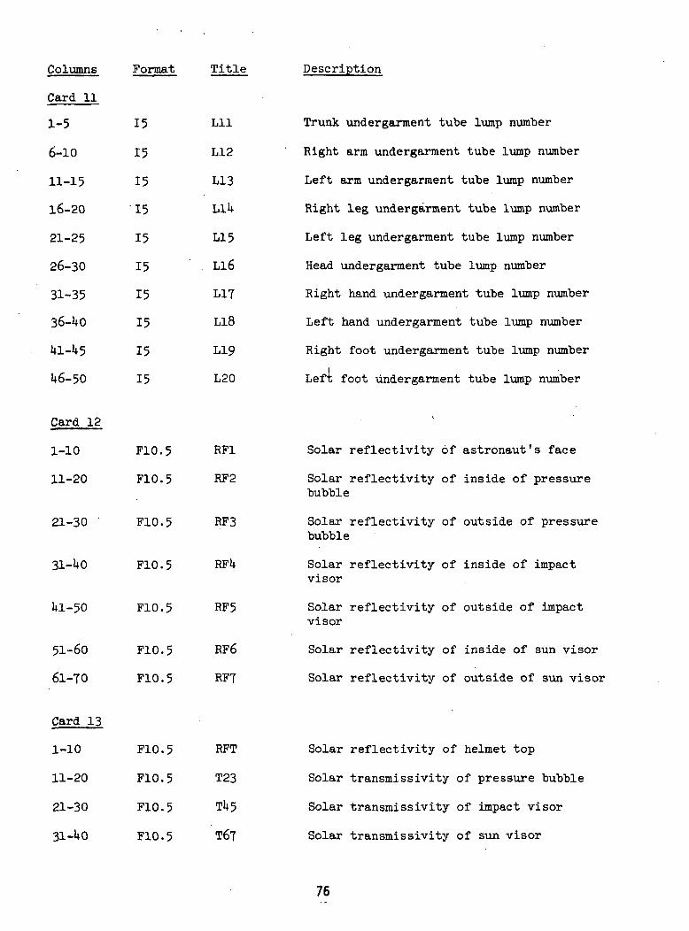
Columns
Card 11
1-5
6-10
11-15
16-20
21-25
26-30
31-35
36-kO
HL-H5
H6-50
Card 12
1-10
11-20
21-30 '
31-HO
HL-50
51-60
61-70
Card 13
1-10
11-20
21-30
31 -HO
Format
15
15
15
•15
15
15
15
15
15
15
F10.5
F10.5
F10.5
F10.5
F10.5
F10.5
F10.5
Fl.0. 5
FLO. 5.
F10.5
FLO. 5
Title
Lll
LI 2
L13
LLH
LI 5
. Ll6
LI?
L18
L19
L20
RF1
RF2
RF3
RFU
RF5
RF6
RF7
RFT
T23
Til 5
T67
Description
Trunk undergarment tube lump number
Right arm undergarment tube lump number
Left arm undergarment tube lump number
Right leg undergarment tube lump number
Left leg undergarment tube lump number
Head undergarment tube lump number
Right hand undergarment tube lump number
Left hand undergarment tube lump number
Right foot undergarment tube lump numberi
Left foot undergarment tube lump number
Solar reflectivity of astronaut's face
Solar reflectivity of inside of pressurebubble
Solar reflectivity of outside of pressurebubble
Solar reflectivity of inside of impactvisor
Solar reflectivity of outside of impactvisor
Solar reflectivity of inside of sun visor
Solar reflectivity of outside of sun visor
Solar reflectivity of helmet top
Solar transmissivity of pressure bubble
Solar transmissivity of impact visor
Solar transmissivity of sun visor
76
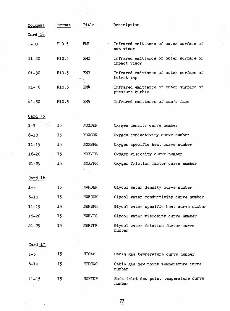
Columns
Card I1*
1-10
11-20
21-30
31-UO
Ul-50
Card 15
1-5 ;
6-10
11-15
16-20
21-25
Card 16
1-5
6-10
11-15
16-20
21-25
Card IT
1-5
6-10
Format
F10.5
F10.5
F10.5
F10.5
F10.5
15
15
15
15
15
15
15
15
15
15
15
15
Title
EMI
EM2
EM3
EMU
EM5
NOXDEN
NOXCON
NOXSPH
NOXVIS
NOXFFR
NVRDEN
NWRCON
NWRSPH
NWRVIS
NWRFFR
NTCAB
NTDEWC
Description
Infrared emittance of outer surface ofsun visor
Infrared emittance of outer surface ofimpact visor
Infrared emittance of outer surface ofhelmet top
Infrared emittance of outer surface ofpressure bubble
Infrared emittance of man's face
Oxygen density curve number
Oxygen conductivity curve number
Oxygen specific heat curve number
Oxygen viscosity curve number
Oxygen friction factor curve number
Glycol water density curve number
Glycol vater conductivity curve number
Glycol vater specific heat curve number
Glycol water viscosity curve number
Glycol water friction factor curvenumber
11-15 15 NOXYDP
Cabin gas temperature curve number
Cabin gas dew point temperature curvenumber
Suit inlet dew point temperature curvenumber
77
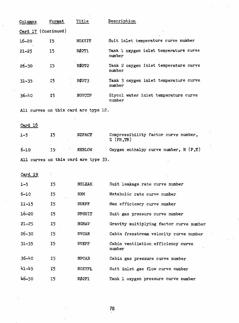
Format Title
Card IT (Continued)
16-20
21-25
26-30
31-35
36-UO
15
15
15
15
15
NOXYIT
N02T1
N02T2
N02T3
NGYCTP
Description
Suit inlet temperature curve number
Tank 1 oxygen inlet temperature curvenumber
Tank 2 oxygen inlet temperature curvenumber
Tank 3 oxygen inlet temperature curvenumber
Glycol water inlet temperature curvenumber
All curves on this card are type 12.
Card 18
1-5 15 NZFACT Compressibility factor curve number,Z (PR.TR)
6-10 15- NEBLOW Oxygen enthalpy curve number, H (P,T)
All curves on this card are type 33.
Card 19
1-5
6-10
11-15
16-20
21-25
26-30
31-35
36-UO
U1-U5
U6-50
15
15
15
15
15
15
15
15
15
15
NSLEAK
MM
NUEFF
NPSUIT
NGRAV
NVCAB
NVEFF
NPCAB
NOXYFL
N02P1
Suit leakage rate curve number
Metabolic rate curve number
Man efficiency curve number
Suit gas pressure curve number
Gravity multiplying factor curve number
Cabin freestream velocity curve number
Cabin ventilation efficiency curvenumber
Cabin gas pressure curve number
Suit inlet gas flow curve number
Tank 1 oxygen pressure curve number
78
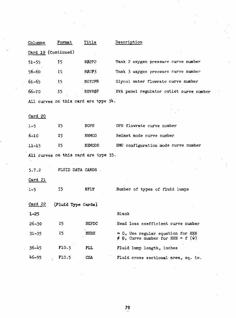
Columns Format
Card 19 (Continued)
51-55 15
56-60 15
61-65 15
66-70 15
Title
N02P2
N0yP3
NGYCFR
NEVR0P
Description
Tank 2 oxygen pressure curve number
Tank 3 oxygen pressure curve number
Glycol water flowrate curve number
EVA panel regulator outlet curve number
All curves on this card are type
Card 20
1-5
6-10
11-15
15
15
15
NOPS
NHMOD
NEMODE
OPS flowrate curve number
Helmet mode curve number
EMU configuration mode curve number
All curves on this card are type 35.
5.7-2
Card 21
1-5
FLUID DATA CARDS
15 NFLT
Card 22 (Fluid Type Cards\
1-25
26-30
31-35
36-1*5
1*6-55
15
15
F10.5
F10.5
NKPDC
NHHH
FLL
CSA
Number of types of fluid lumps
Blank
Head loss coefficient curve number
=» 0, Use regular equation for HHHj£ P, Curve number for HHH = f (w)
Fluid lump length, inches
Fluid cross sectional area, sq. in.
79
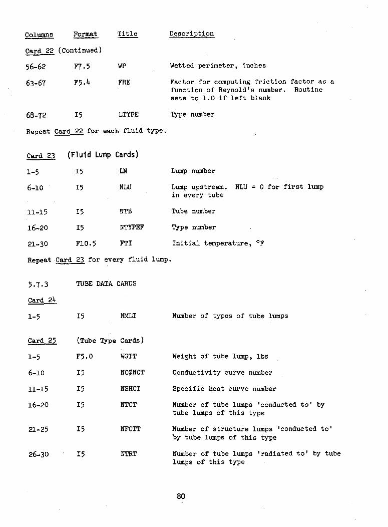
Columns Format Title Description
Card 22 (Continued)
56-62 F7.5
63-67 F5.U
68-72 15
WP
FRE
LTYPE
Wetted perimeter, inches
Factor for computing friction factor as afunction of Reynold's number. Routinesets to 1.0 if left blank
Type number
Repeat Card 22 for each fluid type.
Card 23 (Fluid Lump Cards)
1-5
6-10
11-15
16-20
21-30
Repeat Card
5.7.3
Card 2k
1-5
Card 25
1-5
6-10
11-15
16-20
15
15
15
15
F10.5
LN :
NLU
NTB
NTYPEF
FTI
23 for every fluid lump.
TUBE DATA
15
(Tube Type
F5.0
15
15
15
CARDS
NMLT
Cards)
WGTT
NC0NCT
NSHCT
NTCT
Lump number
Lump upstream. NLU = 0 for first lumpin every tube
Tube number
Type number
Initial temperature, °F
Number of types of tube lumps
21-25
26-30
15
15
NFCTT
NTRT
Weight of tube lump, Ibs
Conductivity curve number
Specific heat curve number
Number of tube lumps 'conducted to' bytube lumps of this type
Number of structure lumps 'conducted to'by tube lumps of this type
Number of tube lumps 'radiated to' by tubelumps of this type
80
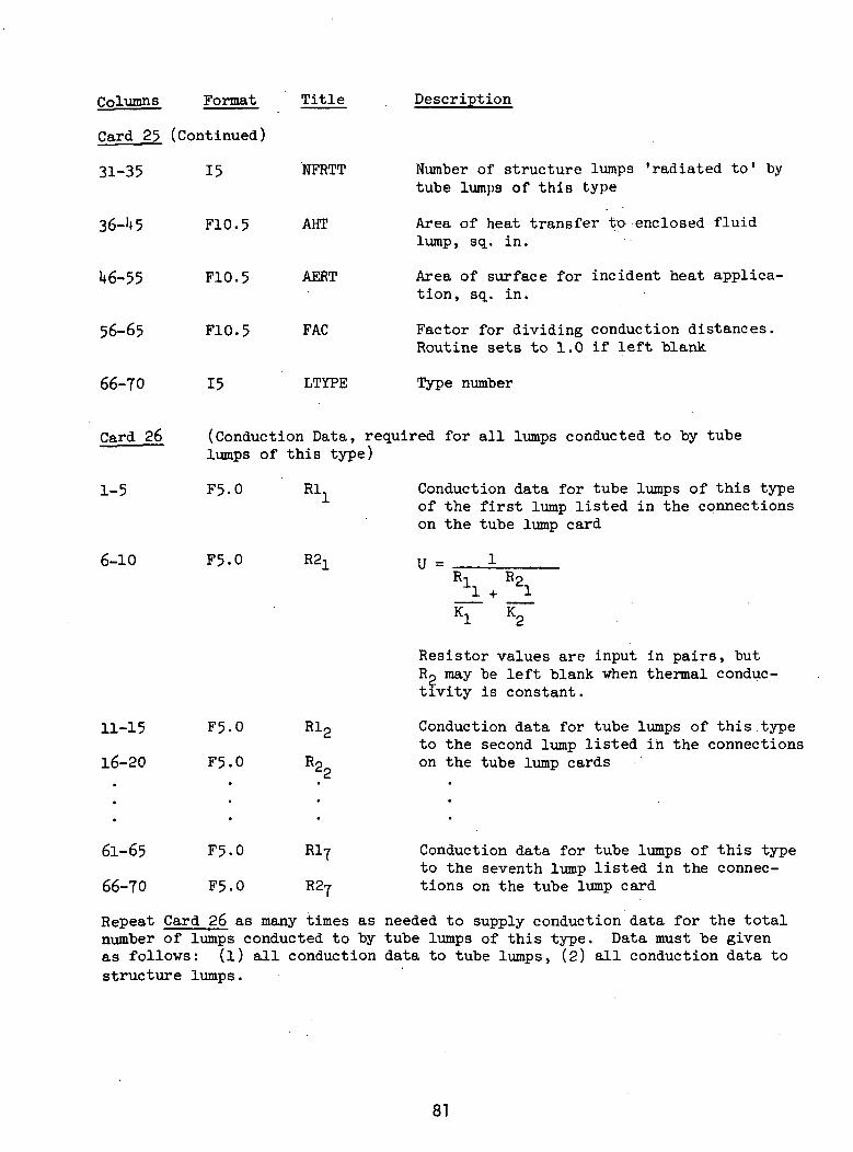
Columns Format Title
Card 25 (Continued)
NFRTT31-35
36-U5
U6-55
56-65
66-70
15
F10.5
F10.5
F10.5
15
AHT
AERT
FAC
LTYPE
Description
Number of structure lumps 'radiated to1 bytube lumps of this type
Area of heat transfer to enclosed fluidlump, sq. in.
Area of surface for incident heat applica-tion, sq. in.
Factor for dividing conduction distances.Routine sets to 1.0 if left blank
Type number
Card 26
1-5
6-10
(Conduction Data, required for all lumps conducted to by tubelumps of this type)
F5.0
F5.0
Rl, Conduction data for tube lumps of this typeof the first lump listed in the connectionson the tube lump card
U =Ro
K,
11-15
16-20
F5.0
F5.0
EIr
Resistor values are input in pairs, butRO may be left blank vhen thermal conduc-tivity is constant.
Conduction data for tube lumps of this typeto the second lump listed in the connectionson the tube lump cards
61-65
66-70
F5-0
F5.0
Rlj
R27
Conduction data for tube lumps of this typeto the seventh lump listed in the connec-tions on the tube lump card
Repeat Card 26 as many times as needed to supply conduction data for the totalnumber of lumps conducted to by tube lumps of this type. Data must be givenas follows: (l) all conduction data to tube lumps, (2) all conduction data tostructure lumps.
81
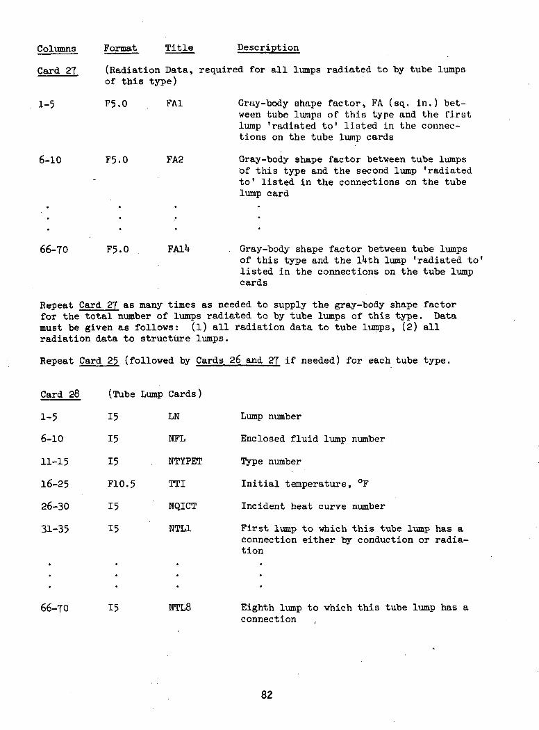
Columns Format Title Description
Card 27
1-5
6-10
(Radiation Data, required for all lumps radiated to by tube lumpsof this type)
F5.0 FA1
F5.0 FA2
Gray-body shape factor, FA (sq.. in.) bet-ween tube lumps of this type and the firstlump 'radiated to' listed in the connec-tions on the tube lump cards
Gray-body shape factor betveen tube lumpsof this type and the second lump 'radiatedto" listed in the connections on the tubelump card
66-70 F5.0 YAlk Gray-body shape factor between tube lumpsof this type and the lUth lump 'radiated to'listed in the connections on the tube lumpcards
Repeat Card 27 as many times as needed to supply the gray-body shape factorfor the total number of lumps radiated to by tube lumps of this type. Datamust be given as follows: (l) all radiation data to tube lumps, (2) allradiation data to structure lumps.
Repeat Card 25 (followed by Cards 26 and 27 if needed) for each tube type.
Card 28
1-5
6-10
11-15
16-25
26-30
31-35
(Tube Lump Cards)
15
15
15
F10.5
15
15
LN
NFL
NTYPET
TTI
NQICT
NTL1
Lump number
Enclosed fluid lump number
Type number
Initial temperature, °F
Incident heat curve number
First lump to which this tube lump has aconnection either by conduction or radia-tion
66-70 15 NTL8 Eighth lump to which this tube lump has aconnection
82
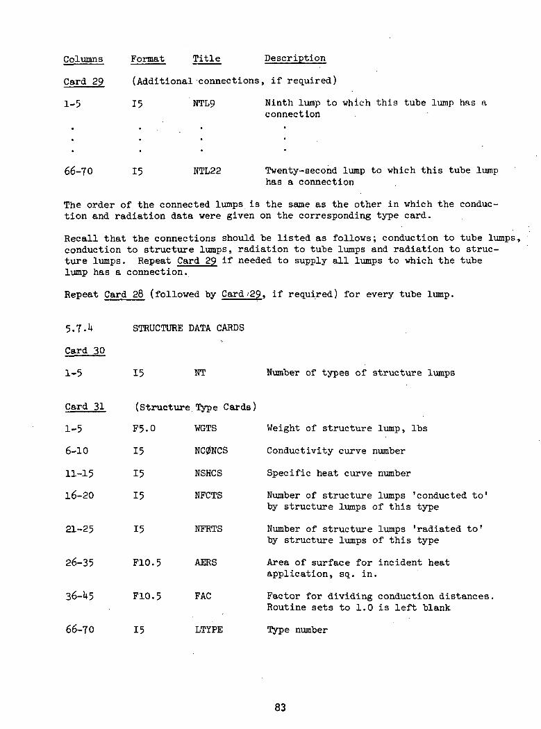
Columns Format Title Description
Card 29 (Additional connections, if required)
1-5 15 NTL9 Ninth lump to which this tube lump has aconnection
66-70 15 NTL22 Twenty-second lump to which this tube lumphas a connection
The order of the connected lumps is the same as the other in which the conduc-tion and radiation data were given on the corresponding type card.
Recall that the connections should be listed as follows; conduction to tube lumps,conduction to structure lumps, radiation to tube lumps and radiation to struc-ture lumps. Repeat Card 29 if needed to supply all lumps to which the tubelump has a connection.
Repeat Card 28 (followed by Card /29, if required) for every tube lump.
5.7.U STRUCTURE DATA CARDS
Card 30
1-5 15 NT Number of types of structure lumps
Card 31 (Structure Type Cards)
1-5 F5.0 WGTS Weight of structure lump, Ibs
6-10 15 NC0NCS Conductivity curve number
11-15 15 NSHCS Specific heat curve number
16-20 15 NFCTS Number of structure lumps 'conducted to'by structure lumps of this type
21-25 15 NFRTS Number of structure lumps 'radiated to'by structure lumps of this type
26-35 F10.5 AERS Area of surface for incident heatapplication, sq. in.
36-U5 F10.5 FAC Factor for dividing conduction distances.Routine sets to 1.0 is left blank
66-70 15 LTYPE Type number
83

Columns
Card 32
1-5
6-10
Format Title Description
(Conduction Data, required for all lumps conducted to by structurelumps of this type)
F5.0
F5-0
Rl1
R2-,
Conduction data for structure lumps of thintype to the first lump listed in the connec-tions on the structure lump card
61-65 F5-0 R17
66-70 F5-0 R2?
Repeat Card 32 as needed.
Card 33
1-5
(Radiation Data, required for all lumps radiated to by structure lumpsof this type)
F5-0 FA1 Gray-body shape factor, FA (in ), betweenstructure lumps of this type and the firstlump 'radiated to1 listed in the connectionson the structure lump cards
66-70 F5.0 FAlU
Repeat Card 33 as needed.
Repeat Card 31 (followed by Cards 32 and 33. if needed) for each structure type.
Card
1-5
6-10
11-20
21-25
26-30
(Structure Lump Cards)
15
15
F10.5
15
15
LN
NTYPES
STI
NQICS
NTL1
Lump number
Type number
Initial temperature, °F
Incident heat curve number
First lump to which this structure lump hasa connection either by conduction or radia-tion
66-70 15 NTL9 Ninth lump to which this structure lump hasa connection
84
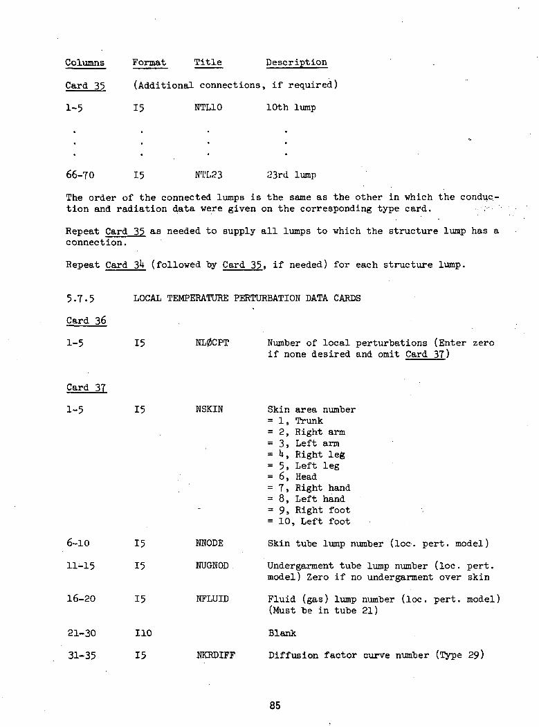
Columns Format Title Description
Card 35 (Additional connections, if required)
1-5 15 NTL10 10th lump
66-70 15 NTL23 23rd lump
The order of the connected lumps is the same as the other in which the conduc-tion and radiation data were given on the corresponding type card. •-•:-•'
Repeat Card 35 as needed to supply all lumps to which the structure lump has aconnection.
Repeat Card 3*+ (followed by Card 35, if needed) for each structure lump.
5.7.5
Card 36
1-5
LOCAL TEMPERATURE PERTURBATION DATA CARDS
15 NL0CPT Number of local perturbations (Enter zeroif none desired and omit Card 37)
Card 37
1-5
16-20
21-30
31-35
15
15
110
15
NSKIN
6-10
11-15
15
15
MODE
NUGNOD
NFLUID
NKRDIFF
Skin area number= 1, Trunk= 2, Right arm= 3, Left arm= U, Right leg= 5, Left leg= 6, Head= 7, Right hand= 8, Left hand= 9, Right foot= 10, Left foot
Skin tube lump number (loc. pert, model)
Undergarment tube lump number (loc. pert,model) Zero if no undergarment over skin
Fluid (gas) lump number (loc. pert, model)(Must be in tube 21)
Blank
Diffusion factor curve number (Type 29)
85
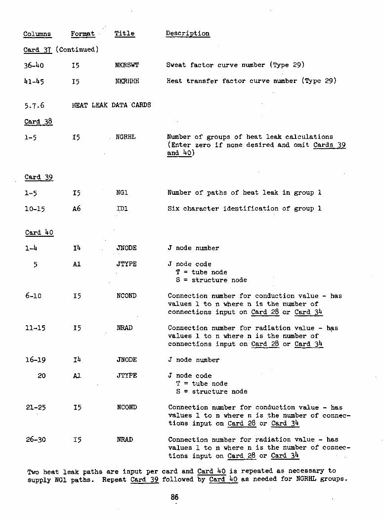
Columns Format Title Description
Card 37 (Continued)
36-UO 15 NKBSWT
ll 1-1*5 15 NKRHHH
Sweat factor curve number (Type 29)
Heat transfer factor curve number (Type 29)
5.7-6
Card 38
1-5
HEAT LEAK DATA CARDS
15 . NGRHL Number of groups of heat leak calculations(Enter zero if none desired and omit Cards 39and 1*0)
Card 39
1-5
10-15
15
A6
NG1
ID1
Number of paths of heat leak in group 1
Six character identification of group 1
Card 1*0
l-U
5
II*
Al
JNODE
JTYPE
6-10
11-15
16-19
20
21-25
26-30
15
15
IU
Al
15
15
NCOND
NRAD
JWODE
JTYPE
NCOND
NRAD
J node number
J node codeT = tube nodeS = structure node
Connection number for conduction value - hasvalues 1 to n -where n is the number ofconnections input on Card 28 or Card 3**
Connection number for radiation value - hasvalues 1 to n where n is the number ofconnections input on Card 28 or Card 3^
J node number
J node codeT = tube nodeS = structure node
Connection number for conduction value - hasvalues 1 to n where n is the number of connec-tions input on Card 28 or Card 3**
Connection number for radiation value - hasvalues 1 to n where n is the number of connec-tions input on Card 28 or Card 3
Two heat leak paths are input per card and Card UP is repeated as necessary tosupply NG1 paths. Repeat Card 39 followed by Card UP as needed for NGRHL groups.
86
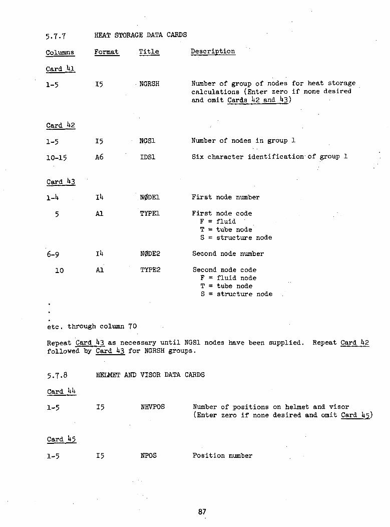
5.7.7
Columns
Card 1*1
1-5
HEAT STORAGE DATA CARDS
Format Title Description
15 NGRSH Number of group of nodes for heat storagecalculations (Enter zero if none desiredand omit Cards h2 and 1*3)
Card 1*2
1-5
10-15
Card 143
1-U
5
15
A6
IU
Al
NGS1
IDS1
N0DE1
TYPE1
6-9
10
IU
Al
N0DE2
TYPE2
Number of nodes in group 1
Six character identification- of group 1
First node number
First node codeF = fluidT = tube nodeS = structure node
Second node number
Second node codeF = fluid nodeT = tube nodeS = structure node
etc. through column 70
Repeat Card U3 as necessary until NGS1 nodes have been supplied,followed by Card U3 for NGRSH groups.
Repeat Card U2
5.7-8
Card UU
1-5
HELMET AND VISOR DATA CARDS
15 NHVPOS Number of positions on helmet and visor(Enter zero if none desired and omit Card
Card U5
1-5 15 NPOS Position number
87

Columns Format Title Description
Card 1*5 (Continued)
6-10 15
11-15 15
16-20 15
21-25 15
26-30 15
31-35 15
36-1*0 15
1+1-U5 15
U6-50 15
51-55 15
Repeat Card 1*£
NTYPE
N0DE1
NR1
NS1
N0DE2
NR2
NS2
N0DE3
NR3
NS3
NHVPOS times
5.7.9 SUIT, GLOVES, AND
Card 1*6
1-5 15
Card U7
1-1* 11*
5 Al
NLMPID
LUMP
IDEN
Position type1 - Sun visor2 - Impact visor3 - Top of helmet1* - Pressure bubble5 - Face
Node number for Mode 1 (Both visors down)
Incident IR flux curve number
Incident solar flux curve number
Node number for Mode 2 (Sun visor up)
Incident IR flux curve number
Incident solar flux curve number
Node number for Mode 3 (Both visors up)
Incident IR flux curve number
Incident solar flux curve number
EV BOOTS NODE IDENTIFICATION DATA CARDS
Total number of structure node comprisingsuit, gloves, & boots (Enter zero if nonedesired and omit Card 1*7)
Node number
Identification codeG = Glove nodeS = Suit nodeB = EV boot node
etc. through column 70
Repeat Card 1*7 as necessary to identify all suit, glove, and boot nodes.
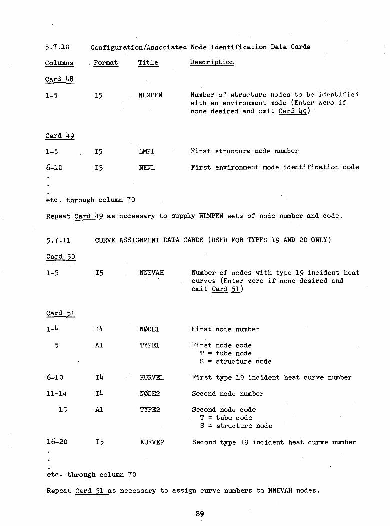
5.7-10
Columns
Cord US
1-5
Configuration/Associated Node Identification Data Cards
. Format Title Description
15 NLMPEN Number of structure nodes to be identifiedwith an environment mode (Enter zero ifnone desired and omit Card
Card U9
1-5
6-10
15
15
LMP1
NEN1
First structure node number
First environment mode identification code
etc. through column TO
Repeat Card 1+9 as necessary to supply NLMPEN sets of node number and code.
5.7.11
Card 50
1-5
CURVE ASSIGNMENT DATA CARDS (USED FOR TYPES 19 AND 20 ONLY)
15 NNEVAH Number of nodes with type 19 incident heat. curves (Enter zero if none desired andomit Card 51)
Card 51
6-10
15
16-20
IU
Al
IkAl
15
N0DE1 First node number
TYPE1 First node codeT = tube nodeS = structure node
KURVE1 First type 19 incident heat curve number
N0DE2 Second node number
TYPE2 Second node codeT = tube codeS = structure node
KURVE2 Second type 19 incident heat curve number
etc. through column 70
Repeat Card 51 as necessary to assign curve numbers to NNEVAH nodes.
89
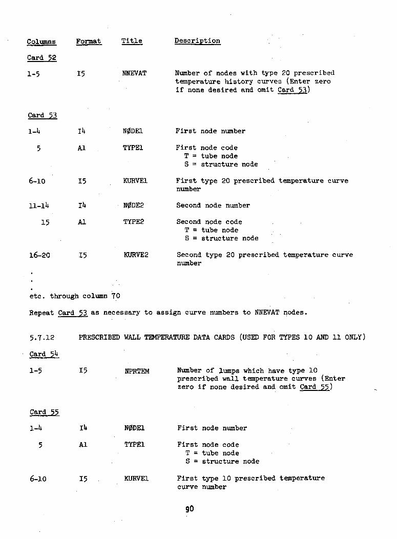
Format Title Description
Card 52
1-5 15 NNEVAT Number of nodes with type 20 prescribedtemperature history curves (Enter zeroif none desired and omit Card 53)
Card 53
6-10
16-20
Al
15
11-lU
15
IU
Al
N0DE2
TYPE2
15
N0DE.1 First node number
TYPE1 First node codeT = tube nodeS = structure node
KURVE1 First type 20 prescribed temperature curvenumber
Second node number
Second node codeT = tube nodeS = structure node
KURVE2 Second type 20 prescribed temperature curvenumber
etc. through column 70
Repeat Card 53 as necessary to assign curve numbers to NNEVAT nodes.
5.7-12
Card 51
1-5
PRESCRIBED WALL TEMPERATURE DATA CARDS (USED FOR TYPES 10 AND 11 ONLY)
15 NPRTEM Number of lumps which have type 10prescribed wall temperature curves (Enterzero if none desired and omit Card 55)
Card 55
1-U lU
5 Al
6-10 15
N0DE1 First node number
TYPE1 First node codeT = tube nodeS = structure node
KURVE1 First type 10 prescribed temperaturecurve number
90
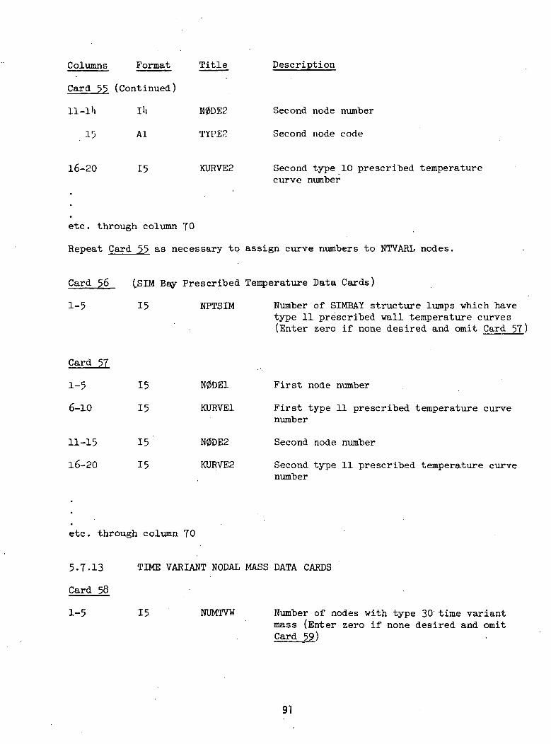
Columns Format Title Description
Card 55 (Continued)
ll-l'i lit N0DE2 Second node number
1'3 Al TYPES . Second node code
16-20 15 KURVE2 Second type 10 prescribed temperaturecurve number
etc. through column 70
Repeat Card 55 as necessary to assign curve numbers to NTVARL nodes.
Card 56 (.SIM Bay Prescribed Temperature Data Cards)
1-5 15 NPTSIM Number of SIMBAY structure lumps which havetype 11 prescribed wall temperature curves(Enter zero if none desired and omit Card 5T)
Card 57
1-5 15 N0DE1 First node number
6-1.0 15 KURVE1 First type 11 prescribed temperature curvenumber
11-15 15 N0DE2 Second node number
16-20 15 KURVE2 Second type 11 prescribed temperature curvenumber
etc. through column 70
5-7.13 TIME VARIANT NODAL MASS DATA CARDS
Card 58
1-5 15 NUMTVW Number of nodes with type 30 time variantmass (Enter zero if none desired and omitCard 59)
91
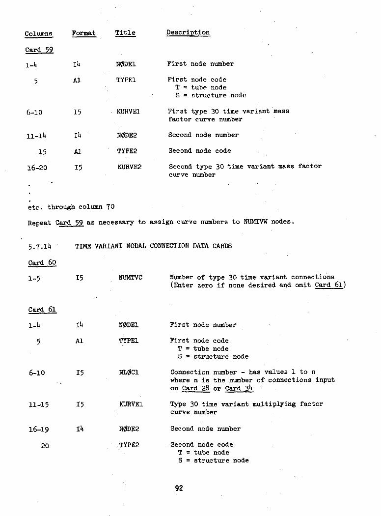
Columns Format Title Description
Card 59
6-10
11-lU
15
16-20
IU
Al
15
IU
Al
15
N0DE1 First node number
TYPE1 First node codeT = tube nodeS = structure node
KURVEl First type 30 time variant massfactor curve number
N0DE2 Second node number
TYPE2 Second node code
KURVE2 Second type 30 time variant mass factorcurve number
etc. through column 70
Repeat Card 59 as necessary to assign curve numbers to NUMTVW nodes.
5.7-11*
Card 60
1-5
TIME VARIANT NODAL CONNECTION DATA CARDS
15 NUMTVC Number of type 30 time variant connections(Enter zero if none desired and omit Card 6l)
Card 61
6-10
11-15
16-19
20
IU
Al
15
15
N0DE1 First node number
TYPE1 First node codeT = tube nodeS = structure node
NL0C1 Connection number - has values 1 to nwhere n is the number of connections inputon Card 28 or Card 3U
KURVEl Type 30 time variant multiplying factorcurve number
N0DE2 Second node number
TYPE2 Second node codeT = tube nodeS = structure node
92
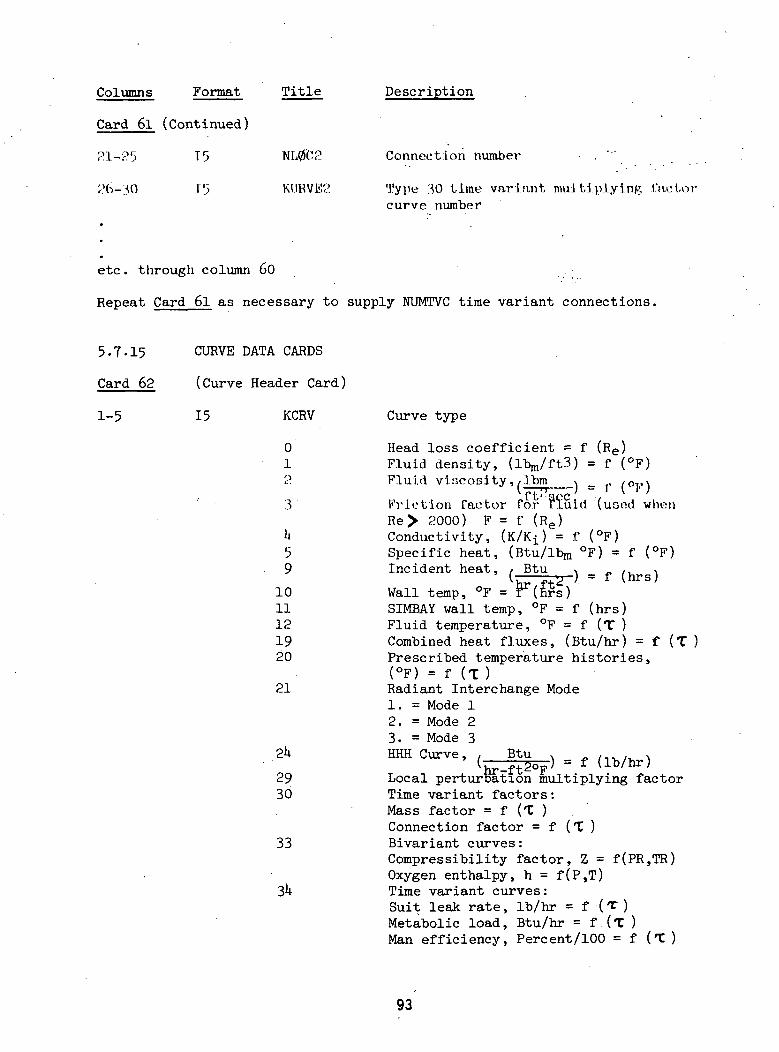
Columns Format Title Description
Card 6l (Continued)
21-25 T5
I" 5
NL002 Connection number . " '
KVIRVE2 Type 30 time variant multiplying 1'acLot-curve number
etc. through column 60
Repeat Card 6l as necessary to supply NUMTVC time variant connections.
5.7.15 CURVE DATA CARDS
Card 62 (Curve Header Card)
1-5 15 KCRV
01Q
1459
1011121920
21
2k
2930
33
Curve type
Head loss coefficient = f (Re)Fluid density, (ibjn/ftS) = f (°F)
) = f (°F)Fluid viscosity,/Ibm
Friction factor for fluid (uood whenRe> 2000) FConductivity,Specific heatIncident heat
= f (Re)(K/K-jJ = f (°F)
, (Btu/lbm °F) = f, / Btu
f (hrs)Wall temp, °FSIMBAY wall temp, °F = f (hrs)Fluid temperature, °F = f (T )Combined heat fluxes, (Btu/hr) = 'f (T )Prescribed temperature histories,(°F) = f (T)Radiant Interchange Mode1. = Mode 12. = Mode 23. = Mode 3HHH Curve, . Btu f (Ib/hr)Local perturbation multiplying factorTime variant factors:Mass factor = f (T )Connection factor = f (T )Bivariant curves:Compressibility factor, Z = f(PR,TR)Oxygen enthalpy, h = f(P,T)Time variant curves:Suit leak rate, Ib/hr = f (T )Metabolic load, Btu/hr = f (T )Man efficiency, Percent/100 = f (T )
93
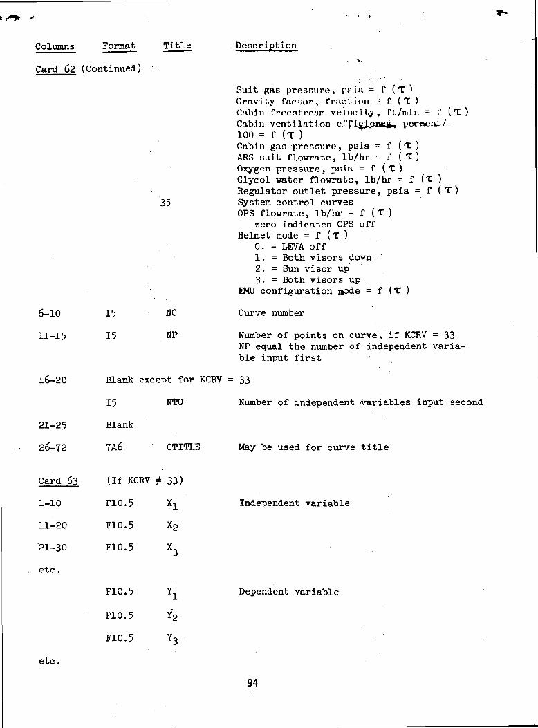
Columns Format Title Description
Card 62 (Continued)
6-10
11-15
16-20
35
15
15
NC
NP
Blank except for KCRV
15 NTU
21-25
26-72
Card 63
1-10
11-20
21-30
etc .
Blank
7A6
(If KCRV 7
F10.5
F10.5
F10.5
F10.5
F10.5
CTI1
t 33)
xl
X2
X3
Yl
Y2
Suit gas pressure, psia = f (T )Gravity factor, fraction = I' (T )Cfibin freestream velocity, f't/min = 1' (t)Cab.1n ventilation e.rfi£J.ene£, pereent/100 = f (T )Cabin gas pressure, psia = f (l )ARG suit flowrate, Ib/hr = f ( T)Oxygen pressure, psia = f (T )Glycol water flowrate, Ib/hr = f (T )Regulator outlet pressure, psia = f (T)System control curvesOPS flowrate, Ib/hr = f (T )
zero indicates OPS offHelmet mode = f (T )
0. = LEVA off1. = Both visors down2. = Sun visor up3- = Both visors up
EMU configuration mode = f (T )
Curve number
Number of points on curve, if KCRV = 33NP equal the number of independent varia-ble input first
= 33
Number of independent variables input second
May be used for curve title
Independent variable
Dependent variable
F10.5
etc.
94
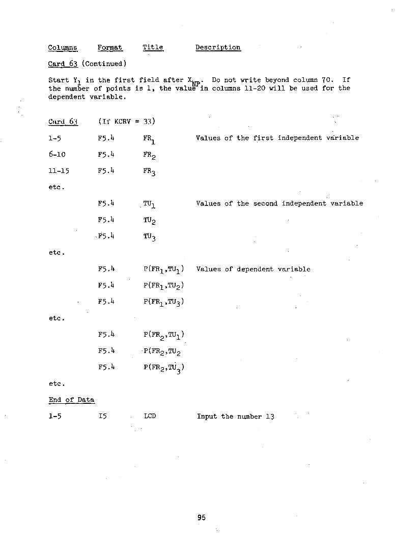
Columns Format Title Description
Card 63 (Continued)
Start Y-L in the first field after X: . Do not write beyond column TO. Ifthe number of points is 1, the value in columns 11-20 will be used for thedependent variable.
Card 63 (If KCRV =33)
1-5 F5.U FR1 Values of the first independent variable
6-10 F5.lt FR2
11-15 F5.lt FR3
etc.
F5.lt TU- Values of the second independent variable
F5.U TU2
F5.lt TU3
etc.
F5.lt P(FR^,TU^) Values of dependent variable
F5.U P(FRl5TU2)
F5.lt P(FR1,TU3)
etc.
F5.lt P(FR2,TU1)
F5.lt P(FR2,TU2
F5.lt P(FR2,TU )
etc.
End of Data
1-5 15 LCD Input the number 13
95
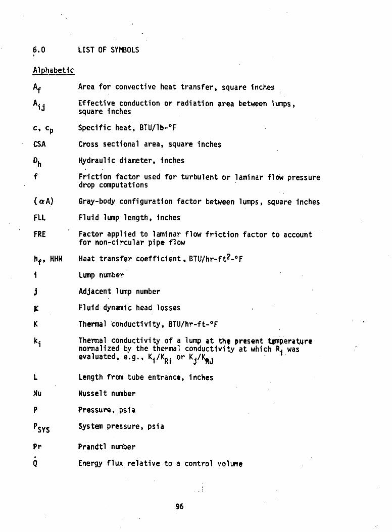
.6.0 LIST OF SYMBOLS.•
Alphabetic
Af Area for convectlve heat transfer, square Inches
A^ Effective conduction or radiation area between lumps,J square inches
c, cp Specific heat, BTU/lb-°F
CSA Cross sectional area, square inches
Djj Hydraulic diameter, inches
f Friction factor used for turbulent or laminar flow pressuredrop computations
(orA) Gray-body configuration factor between lumps, square inches
FLL Fluid lump length, inches
FRE Factor applied to laminar flow friction factor to accountfor non-circular pipe flow
hf, HHH Heat transfer coefficient , BTU/hr-ft2-°F
1 Lump number
j Adjacent lump number
K Fluid dynamic head losses
K Thermal conductivity, BTU/hr-ft-°F
k.j Thermal conductivity of a lump at tht present temperaturenormalized by the thermal conductivity at which R.. wasevaluated, e.g., I./K or
L Length from tube entrance, inches
Nu Nusselt number
P Pressure, psia
PSYJ System pressure, psia
Pr Prandtl number•
Q Energy flux relative to a control volume
96
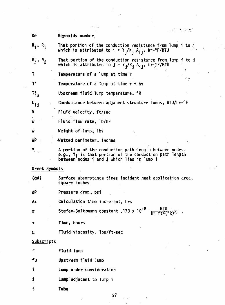
Re Reynolds number
RJ , R, That portion of the conduction resistance from lump i to j1 ' which is attributed to i = Y./K, A^, hr-°F/BTU
RJ, R9 That portion of the conduction resistance from lump i to jJ * which is attributed to j = Y../K.. A..., hr-°F/BTU
T Temperature of a lump at time T
T1 Temperature of a lump at time T + AT
Ti Upstream fluid lump temperature, °R
Uj. Conductance between adjacent structure lumps, BTU/hr-°F
V Fluid velocity, ft/sec
w Fluid flow rate, Ib/hr
w Weight of lump, Ibs
WP Wetted perimeter, inches
Y A portion of the conduction path length between nodes,e.g., Yj is that portion of the conduction path lengthbetween nodes i and j which lies in lump i
Greek Symbols
(otA) Surface absorptance times incident heat application area,square inches
AP Pressure drop, psi
AT Calculation time increment, hrs8 BTUa Stefan-Boltzmann constant .173 x 10 - —=-
T Time, hours
y Fluid viscosity, Ibs/ft-sec
Subscripts
f Fluid lump
fu Upstream fluid lump
i Lump under consideration
j Lump adjacent to lump i
t Tube97
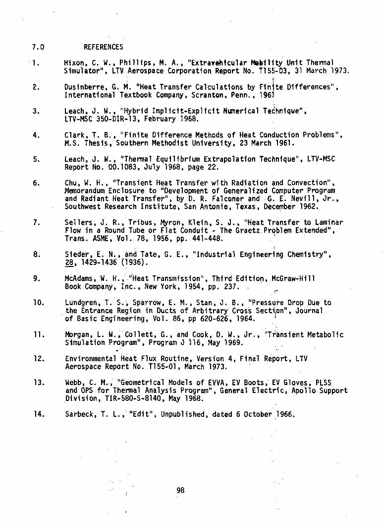
7.0 REFERENCES
1. Hixon. C. W., Phillips, M. A., "Extravehicular Mobility Unit ThermalSimulator", LTV Aerospace Corporation Report No. T155-03, 31 March 1973.
^ f
2. Dusinberre, G. M. "Heat Transfer Calculations by Finite Differences",International Textbook Company, Scranton, Penn., 1961
3. Leach, J. W., "Hybrid Implicit-Explicit Numerical Technique",LTV-MSC 350-DIR-13, February 1968.
4. Clark, T. B., "Finite Difference Methods of Heat Conduction Problems",M.S. Thesis, Southern Methodist University, 23 March 1961.
5. Leach, J. W., "Thermal Equilibrium Extrapolation Technique", LTV-MSCReport No. 00.1083, July 1968, page 22.
6. Chu, W. H., "Transient Heat Transfer with Radiation and Convection",Memorandum Enclosure to "Development of Generalized Computer Programand Radiant Heat Transfer", by D. R. Falconer and G. E. Nevill, Jr.,Southwest Research Institute, San Antonio, Texas, December 1962.
7. Sellers, J. R., Tribus, Myron, Klein, S. J., "Heat Transfer to LaminarFlow in a Round Tube or Flat Conduit - The Graetz Problem Extended",Trans. ASME, Vol. 78, 1956, pp. 441-448.
i
8. Sieder, E. N., and Tate, G. E., "Industrial Engineering Chemistry",28, 1429-1436 (1936).
9. McAdams, W. H., "Heat Transmission", Third Edition, McGraw-HillBook Company, Inc., New York, 1954, pp. 237.
10. Lundgren, T. S., Sparrow, E. M., Stan, J. B., "Pressure Drop Due tothe Entrance Region in Ducts of Arbitrary Cross Section", Journalof Basic Engineering, Vol. 86, pp 620-626, 1964. !
11. Morgan, L. W., Collett, G., and Cook, D. W., Jr., "Transient MetabolicSimulation Program", Program J 116, May 1969.
« *'
12. Environmental Heat Flux Routine, Version 4, Final Report, LTVAerospace Report No. T155-01, March 1973.
13. Webb, C. M.., "Geometrical Models of EVVA, EV Boots, EV Gloves, PLSSand OPS for Thermal Analysis Program", General Electric, Apollo SupportDivision, TIR-580-S-8140, May 1968.
14. Sarbeck, T. L., "Edit", Unpublished, dated 6 October 1966.
98

APPENDIX A
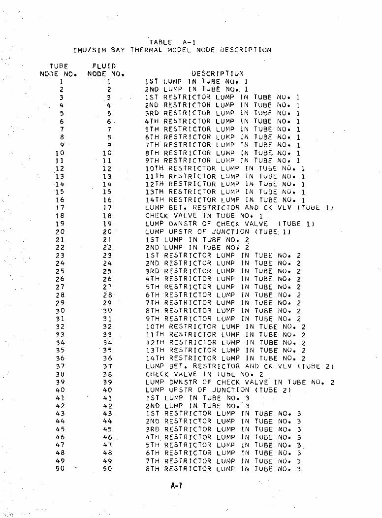
EMU/SIM BAYTABLE A-l
THERMAL MODEL NODE DESCRIPTION
TUBENODE NO.
123456789101112'1314151617181920212223242526272829303132333435363738394041424344454647484950 -
FLUIDNODE NO.
12
.3 - •45678.910.11121314151617181'920'21222324252627282930313233 .3435363738394041424344454647484950
DESCRIPTION1ST LUMP IN TUBE NO. 12ND LUMP IN TUBE NO.. 11ST RESTRICTOR LUMP IN TUBE NU. 12ND RESTRICTOR LUMP IN TUBE NO. 13RD RESTRICTOR LUMP IN TUbE NO. 14TH RESTRICTOR LUMP IN TUBE NO. 15TH RESTRICTOR LUMP IN TUBE NO. 16TH RESTRICTOR LUMP i'N TUBE NO. 17TH RESTRICTOR LUMP 'N TUBE NO. 18TH RESTRICTOR LUMP IN TUBE NO. 19TH RESTRICTOR LUMP IN TUBE NO. 110TH RESTRICTOR LUMP IN TUBE NO. 1HTH RL'bTRlCTOR LUMP IN TUBE NO. 112TH RESTRICTOR LUMP IN TUBE NO. 113TH RESTRICTOR LUMP IN TUBE NO. 114TH RESTRICTOR LUMP IN TUBE NO. 1LUMP BET. RESTRICTOR AND CK VLV (TUBECHECK VALVE IN TUBE NO. 1 .LUMP DWNSTR OF CHECK VALVE (TUBE 1)LUMP UPSTR OF JUNCTION (TUBE; 1)1ST LUMP IN TUBE NO. 22ND LUMP IN TUBE NO. 21ST RESTRICTOR LUMP IN TUBE NO. 22ND RESTRICTOR LUMP IN TUBE NO. 23RD RESTRICTOR LUMP IN TUBE NO. 24TH RESTRICTOR LUMP IN TUBE NO. 25TH RESTRICTOR LUMP IN TUBE NO. 26TH RESTRICTOR LUMP IN TUBE NO. 27TH RESTRICTOR LUMP IN TUBE NO. 28TH RESTRICTOR LUMP IN TUBE NO. 29TH RESTRICTOR LUMP IN TUBE NO. 210TH RESTRICTOR LUMP IN TUBE NO. 211TH RESTRICTOR LUMP IN TUBE NO. 212TH RESTRICTOR LUMP IN TUBE NO. 213TH RESTRICTOR LUMP IN TUBE NO. 214TH RESTRICTOR LUMP IN TUBE NO. 2LUMP BET. RESTRICTOR AND CK VLV (TUBECHECK VALVE IN TUBE NO. 2LUMP DWNSTR OF CHECK VALVE IN TUBE NO.LUMP UPSTR OF JUNCTION (TUBE 2)1ST LUMP IN TUBE NO. 32ND LUMP IN TUBE NO. 31ST RESTRICTOR LUMP IN TUBE NO. 32ND RESTRICTOR LUMP IN TUBE NO. 33RD RESTRICTOR LUMP IN TUBE NO. 34TH RESTRICTOR LUMP IN TUBE NO. 35TH RESTRICTOR LUMP {N TUBE NO. 36TH RESTRICTOR LUMP fN TUBE NO. 37TH RESTRICTOR LUMP IN TUBE NO. 38TH RESTRICTOR LUMP IN TUBE NO. 3
1)
2)
A-l
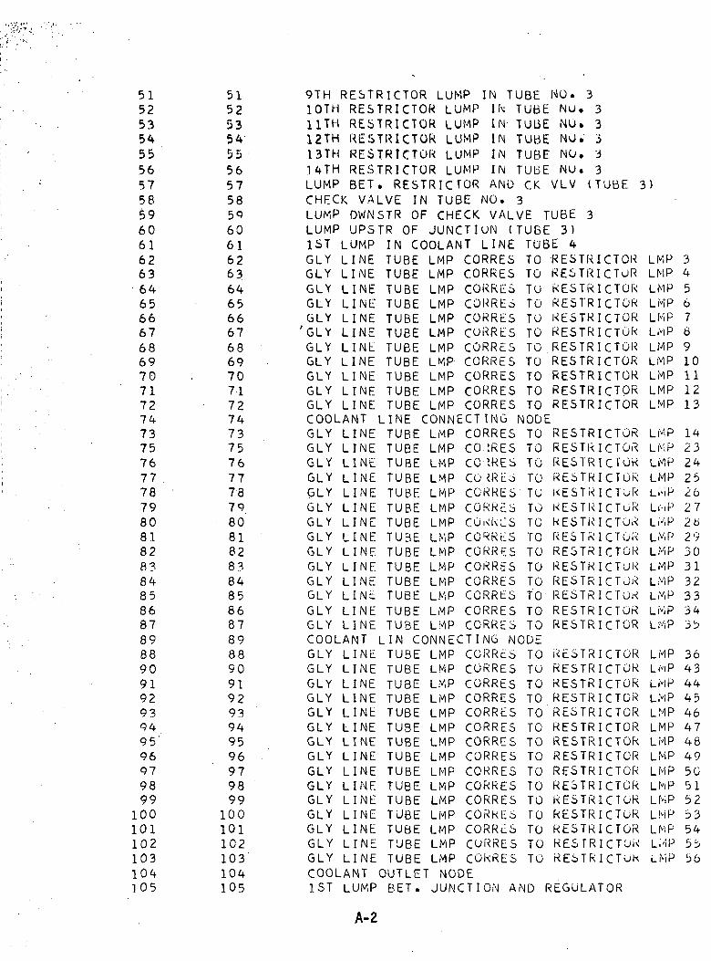
515253545556575859606162636465666768697071727473757677 .78798081828?848586878988909192939495'96979899100101102103104105
51.525354555657585960616263646566676869707172747375767778798081828384858687898890919293949596979899100101102103104105
9TH RESTRICTOR LUMP IN TUBE NO. 310TH RESTRICTOR LUMP 11\ TUBE Nu. 311TH RESTRICTOR LUMP IN TUBE NO. 312TH RESTRICTOR LUMP IN TUBE NO. 313TH RESTRICTOR LUMP IN TUBE NO. 314TH RESTRICTOR LUMP IN TUBE NO. 3LUMP BET. RESTRICTOR AND CK VLV (TUBE 3)CHECK VALVE IN TUBE NO. 3LUMP DWNSTR OF CHECK. VALVE TUBE 3LUMP UPSTR OF JUNCTluN (TUBE 3)1ST LUMP IN COOLANT LINE TUBE 4GLY LINE TUBE LMP CORRES TO RESTRICTORGLY LINE TUBE LMP CORRES TO RESTRICTSGLY LINE TUBE LMP CORRES TO RESTRICTORGLY LINE TUBE LMP CORRES TO RESTRICTORGLY LINE TUBE LMP CORRES TO KESTRICTOR'GLY LINE TUBE LMP CORRES TO RESTRICTORGLY LINE TUBE LMP CORRES TO RESTRICTORGLY LINE TUBE LMP CORRES TO RESTRICTORGLY LINE TUBE LMP CORRES TO RESTRICTORGLY LINE TUBE LMP CORRES TO RESTRICTORGLY LINE TUBE LMP CORRES TO RESTRICTORCOOLANT LINE CONNECTING NODEGLY LINE TUBE LMP CORRES TO RESTRICTORGLY LINE TUBE LMP CO.tRES TO RESTRICTORGLY LINE TUBE LMP CORRES TO RESTRICTORGLY LINE TUBE LMP CO <RES TO RESTRICTORGLY LINE TUBE LMP CORRES TO KESTRICTuRGLY LINE TUBE LMP CORRES TO RESTKICTORGLY LINE TUBE LMP COKKLS TO KESTRICTORGLY LINE TUBE LMP CORRES TO RESTRICTORGLY LINE TUBE LMP CORRES TO RESTRICTORGLY LINE TUBE LMP CORRES TO RESTRICTORGLY LINE TUBE LMP CORRES TO RESTRICTORGLY LINE TUBE LMP CORRES TO RESTRICTOKGLY LINE TUBE LMP CORRES TO RESTRICTORGLY LINE TUBE LMP CORRES TO RESTRICTORCOOLANT LIN CONNECTING NODEGLY LINE TUBE LMP CORRES TO RESTRICTORGLY LINE TUBE LMP CORRES TO RESTRICTORGLY LINE TUBE LMP CORRES TO RESTRICTORGLY LINE TUBE LMP CORRES TO RESTRICTORGLY LINE TUBE LMP CORRES TO'.RESTRICTORGLY LINE TUBE LMP CORRES TO RESTRICTORGLY LINE TUBE LMP CORRES TO RESTRICTOkGLY LINE TUBE LMP CORRES TO RESTRICTORGLY LINE TUBE LMP CORRES TO RESTRICTOKGLY LINE TUBE LMP CORRES.TO RESTRICTORGLY LINE TUBE LMP CORRES TO RESTRICTORGLY LINE TUBE LMP CORRES TO RESTRICTORGLY LINE TUBE LMP CORRcS TO RESTRICTORGLY LINE TUBE LMP CORRES TO KESTRICTOKGLY LINE TUBE LMP CORRES TO RESTRICTOkCOOLANT OUTLET NODE1ST LUMP BET. JUNCTION AND REGULATOR
LMPLMPLMPLMPLMPLMPLMPLMPLMPLMPLMP
LMPLMPLMPLMPLi'iPL^PLHPLMPLMPLMPLMPLMPLMPLMP
LMPLf'iPLHPLHPLMPLMPLMPLMPLMPLMPLMPLMPLMPL.'-iPLMP
345676910111213
1423242526272b29303132333435
364344454647484950515253545b56
A-2
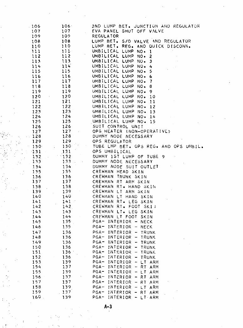
1061071091081101111121131141151161171181191201211221231241251261271281291301311321331341351361371381391401411421431441451461471481.49150151152153154155156157158159160 .
1061071091081101111121.1311411511611711811912012112212312412512612712812913013.11 3 2133134135136137138139140141142143144135135136136136136136136139137139137137139137139
2ND LUMP BET. JUNCTION AND REGULATOREVA PANEL SHUT OFF VALVEREGULATOR
s/o VALVE AND REGULATORREG. AND QUICK DI3CONN.
NO.NO.NO.NO.NO.NO.NO.NO.NO.NO.NO.NO.NO.NO.NO.
LUMP BET.LUMP BET.UMBILICALUMBILICALUMBILICALUMBILICALUMBILICALUMBILICALUMBILICALUMBILICALUMBILICALUMBILICALUMBILICALUMBILICALUMBILICALUMBILICALUMBILICAL
123456789101112131415
LUMPLUMPLUMPLUMPLUMPLUMPLUMPLUMPLUMPLUMPLUMPLUMPLUMPLUMPLUMP
SUIT CONTROL UNITOPS HEATER (NON-OPERATIVc)DUMMY NODE NECESSARYOPS REGULATORTUBE LMP BET. OPS REG.OPS UMBILICALDUMMY 1ST LUMP OF TUBEDUMMY NODE NECESSARYDUMMY NODE SUIT OUTLETCREWMAN HEAD SKINCREWMAN TRUNK SKINCREWMAN RT ARM SKINCREWMAN RT. HAND SKINCREWMAN LT ARM SKINCREWMAN LT HAND SKINCREWMAN RT. LEG SKINCREWMAN RT. FOOT SKI ICREWMAN LT. LEG SKINCREWMAN LT FOOT SKINPGA- INTERIOR - NECKPGA- INTERIOR - NECKPGA- INTERIOR - TRUNKPGA- INTERIOR - TRUNKPGA- INTERIOR - TRUNKPGA- INTERIOR - TRUNKPGA- INTERIOR - TRUNKPGA- INTERIOR - TRUNKPGA- INTERIOR - LT ARMPGA- INTERIOR - RT ARMPGA- INTERIOR - LT ARMPGA- INTERIOR - RT ARMPGA- INTERIOR - RT ARMPGA- INTERIOR - LT ARMPGA- INTERIOR - RT ARMPGA- INTERIOR - LT ARM
AND OPS UMBIL.
A-3
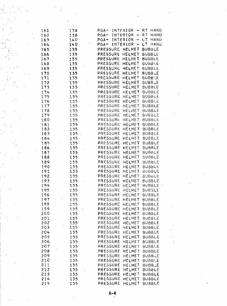
161162163164165166167168169170171172173174175176177178179180181182183184'185186187188189190191192193194195196197198199200201202203204205206207208209210211212213214215
138138140140135135135135135135135135135135135135135135135135135135135135135135135135135135135135135135135135135135135135135135135135135135135135135135135135135135135
PGA- INTERIOR -PGA- INTERIOR -PGA* INTERIOR -PGA- INTERIOR -PRESSURE HELMETPRESSURE HELMET-PRESSURE HELMETPRESSURE HELMETPRESSURE HELMETPRESSURE HELMETPRESSURE HELMETPRESSURE HELMETPRESSURE HELMETPRESSURE HELMETPRESSURE HELMETPRESSURE HELMETPRESSURE HELMETPRESSURE HELMETPRESSURE HELMETPRESSURE HELMETPRESSURE HELMETPRESSURE HELMETPRESSURE HELMETPRESSURE HELMETPRESSURE HELMETPRESSURE HELMETPRESSURE HELMETPRESSURE HELMETPRESSURE HELMETPRESSURE HELMETPRESSURE HELMETPRESSURE HELMETPRESSURE HELMETPRESSURE HELMETPRESSURE HELMETPRESSURE HELMETPRESSURE HELMETPRESSURE HELMETPRESSURE HELMETPRESSURE HELMETPRESSURE HELMETPRESSURE HELMETPRESSURE HELMETPRESSURE HELMETPRESSURE HELMETPRESSURE HELMETPRESSURE HELMETPRESSURE HELMETPRESSURE HELMETPRESSURE HELMETPRESSURE HELMETPRESSURE HELMETPRESSURE HELMETPRESSURE HELMETPRESSURE HELMET
RT HANDRT HANDLT HANDLT HANDBUBBLEBUBBLEB'UBQLEBUBBLEBUBBLtBUBBuEBUBB'.EBUBBLEBUBBLEBUBBLEBUBBLEBUBBLEBUBBLEBUBBLEBUBBLEBUBBLEBUBBLEBUBBLEBUBBLEBUBBLE"BUBBLEBUBBLEBUBBLEBUBBLEBUBBLEBUBBLEBUBBLEBUBBLEBUBBLEBUBBLE 'BUBBLEBUBBLEBUBBLEBUBBLEBUBBLEBUBBLEBUBBLEBUBBLEBUBBLEBUBBLEBUBBLEBUBBLEBUBBLEBUBBLEBUBB..EBUBB'.EBUBB_EBUBBLEBUBBLEBUBBLEBUBBLE
A-4

216217218219220221222223224225226227228229230231232233234235236237238239240241242243244245246247248249250251252-253254255256257258258259
1351351351351351351351351351351351411431411431*1143141143142144142144142144136 .136136136137139135135135135136137139141143142144145145146
PRESSUREPRESSUREPRESSUREPRESSUREPRESSUREPRESSUREPRESSUREPRESSUREPRESSUREPRESSUREPRESSUREPGA - INPGA - INPGA - INPGA - INPGA - IN'PGA - INPGA - INPGA - INPGA - INPGA - INPGA - INPGA - INPGA - INPGA - INPGA - ELOPS - 0202 INLET02 PURGESUIT PRESUIT RELNECKRINGNECKRINGNECKRINGNECKRINGUNDERGARUNDERGARUNDERGARUNDERGARUNDERGARUNDERGARUNDERGARGLY LUMPGLY TUBEGLY TUBE
HELMET BUBBLEHELMET BUBBLEHELMET BUBBLEHELMET BUBBLEHELMET BUBBLEHELMET BUBBLEHELMET BUBBLEHELMET BUBBLEHELMET BUBBLEHELMET BUBBLEHELMET BUBBLE
INTERIORINTERIORINTERIORINTERIORINTERIORINTERIORINTERIORINTERIORINTERIORINTERIORINTERIORINTERIORINTERIORINTERIOR
CT. CONN.CONN.CONN. (UMBILICAL)VALVESURE GAGEEF VALVE
RT.LT.RT.LT.RT.LT.RT.LT.RT.LT.RT.LT.RT.LT.
LEGLEGLEGLEGLEGLEGLEGLEG .FOOTFOOTFOOTFOOTFOOTFOOT
TRUNKARM .ARMLEGLEGFOOTFOOT
RESTRICTOR LUMP 15TO RESTICTOR LMP 15TO RESTICTOR LMP 16
•1ENT RT-1ENT LT4ENT RT1ENT LT/iENT RT4ENT LTCORRESLMP CORRESLMP CORRES
TO
A-5
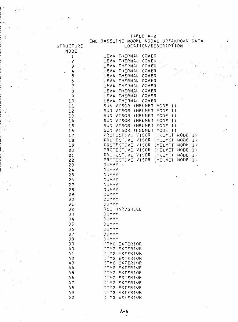
TABLE A-2EMU BASELINE MODEL NODAL BREAKDOWN DATA
STRUCTURENODE
123
. 4567891011121314151617181920212223242526272829303132333435363738394041424344454.647484950
LOCATION/DESCRIPTION -
LEVA THERMAL COVERLEVA THERMAL COVER 'LEVA THERMAL COVER • "LEVA THERMAL COVERLEVA THERMAL COVERLEVA THERMAL COVERLEVA THERMAL COVERLEVA THERMAL COVERLEVA THERMAL COVERLEVA THERMAL COVERSUN VISOR (HELMET MODE 1)
. SUN VISOR (HELMET MODE 1)SUN VISOR (HELMET MODE 1)SUN VISOR (HELMET MODE 1)SUN VISOR (HELMET MODE 1)SUN VISOR (HELMET MODE 1)PROTECTIVE VISOR (HELMET MODEPROTECTIVE VISOR (HELMET MODEPROTECTIVE VISOR (HELMET MODEPROTECTIVE VISOR (HELMET MODEPROTECTIVE VISOR (HELMET MODEPROTECTIVE VISOR (HELMET MODEDUMMY •DUMMYDUMMYDUMMYDUMMYDUMMYDUMMYDUMMYDUMMYRCU HARDSHELLDUMMYDUMMYDUMMYDUMMYDUMMYDUMMYITMG EXTERIORITMG EXTERIORITMG EXTERIORITMG EXTERIORITMG EXTERIORITMG EXTERIORITMG EXTERIORITMG EXTERIORITMG EXTERIORITMG EXTFRIORITMG EXTERIORITMG EXTERIOR
1)1)1)1)1)1)
A-6
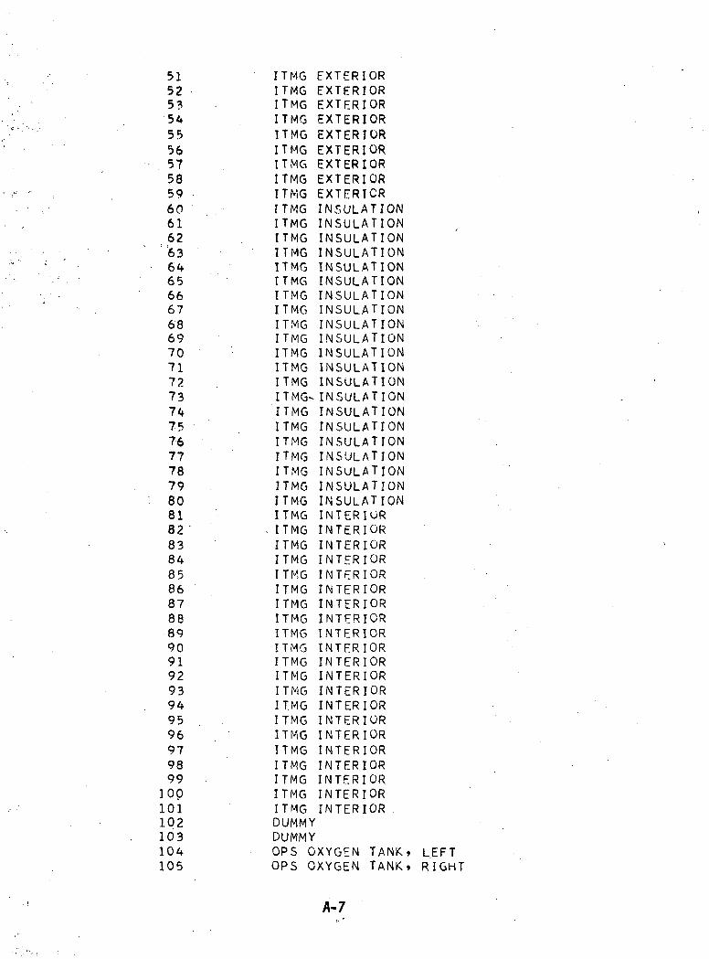
51 ITMG EXTERIOR52 ITMG EXTERIOR53 • ITMG EXTERIOR54 ITMG EXTERIOR55 ITMG EXTERIOR56 ITMG EXTERIOR57 ITMG EXTERIOR58 ITMG EXTERIOR59 ITMG EXTERIOR60 ITMG INSULATION61 ITMG INSULATION62 ITMG INSULATION
:63 ITMG INSULATION64 ITMG INSULATION65 ITMG INSULATION66 ITMG INSULATION67 ITMG INSULATION68 ITMG INSULATION69 ITMG INSULATION70 ITMG INSULATION71 ITMG INSULATION72 ITMG INSULATION73 ITMG-INSULATION74 ITMG INSULATION75 ITMG INSULATION76 ITMG INSULATION77 ITMG INSULATION78 ITMG INSULATION79 . ITMG INSULATION80 ITMG INSULATION81 ITMG INTERIOR82 '• - ITMG INTERIOR83 ITMG INTERIOR84 ITMG INTERIOR85 ITMG INTERIOR86 ITMG INTERIOR87 ITMG INTERIOR88 ITMG INTERIOR89 ITMG INTERIOR90 ITMG INTERIOR91 ITMG INTERIOR92 ITMG INTERIOR93 ITMG INTERIOR94 ITMG INTERIOR95 ITMG INTERIOR96 ITMG INTERIOR97 ITMG INTERIOR98 ITMG INTERIOR99 ITMG INTERIOR
100 ITMG INTERIOR101 ITMG INTERIOR102 DUMMY103 DUMMY104 OPS OXYGEN TANK* LEFT105 OPS OXYGEN TANK* RIGHT
A-7
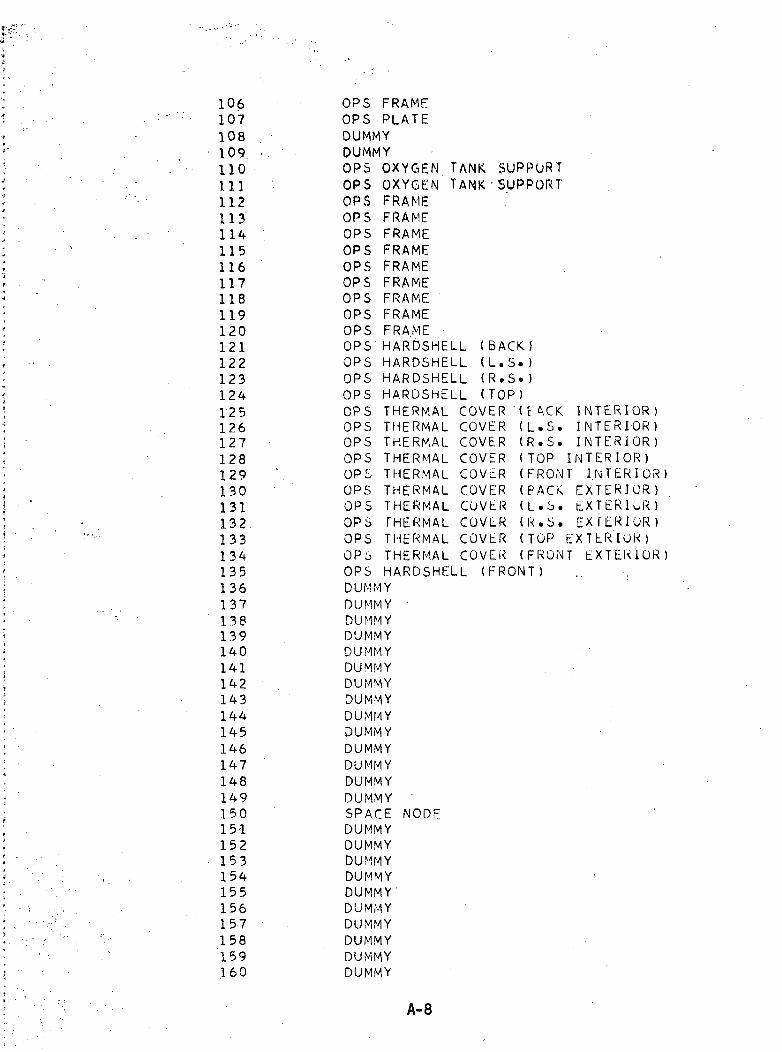
106107108109110111112113114115116117118119120121122123124125126127128129130131132133134135136137138139140141142143144145146147148149150151152153154155156157158159160
TANK SUPPORTTANK-SUPPORT
OPS FRAMEOPS PLATEDUMMYDUMMYOPS OXYGENOPS OXYGENOPS FRAMEOPS FRAMEOPS FRAMEOPS FRAMEOPS FRAMEOPS FRAMEOPS FRAMEOPS FRAMEOPS FRAMEOPS HARDSHELLOPS HARDSHELLOPS HARDSHELLOPS HARDSHELLOPS THERMAL COVEROPS THERMAL COVEROPS THERMAL COVEROPS THERMAL COVEROPS THERMAL COVEROPS THERMAL COVEROPS THERMAL CUVLROPS THERMAL COVLROPS THERMAL COVEROPS THERMAL COVER
(BACK!(L.S.)(R.S.)(TOP)
(E ACK(L.S.(R.S.( TOP I(FRONT(PACK(L.S.(R.S.(TOP E(FRONT
INTERIOR)INTERIOR)INTERIOR)NTERIOR)INTERIOR)
EXTERIOR)EXTERIOR)E X T E R I O R )XTERIOR)EXTERIOR)
OPS HARDSHELLDUMMYDUMMY 'DUMMYDUMMYDUMMYDUMMYDUMMYDUMMYDUMMYDUMMYDUMMYDUMMYDUMMYDUMMYSPACE NODEDUMMYDUMMYDUMMYDUMMYDUMMY'DUMMYDUMMYDUMMYDUMMYDUMMY
(FRONT)
A-8
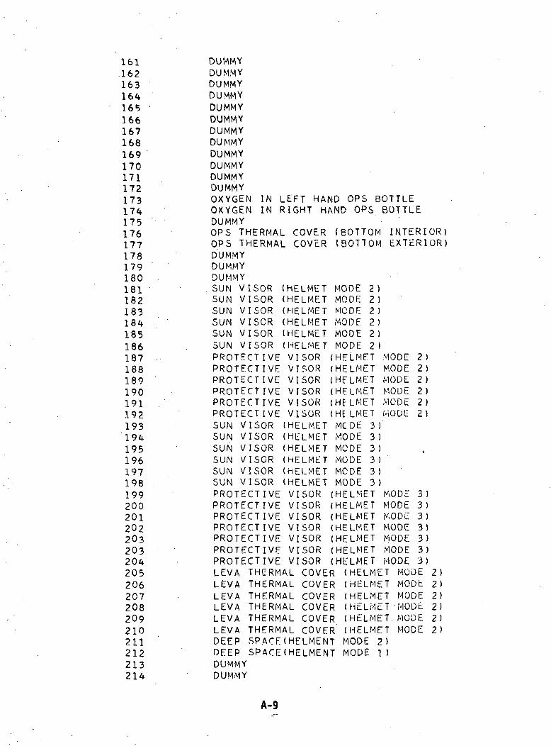
161162163
166167168169170171172173174175176177178179180181182183184185186187188189190191192193194195196197198199200201202203203204205206207208209210211212213214
DUMMYDUMMYDUMMYDUMMYDUMMYDUMMYDUMMYDUMMYDUMMYDUMMYDUMMYDUMMYOXYGEN INOXYGEN INDUMMYOPS THERMALOPS THERMALDUMMYDUMMY'DUMMY.SUN VISORSUN VISORSUN VISORSUN VISORSUN VISORSUN VISORPROTECTIVEPROTECTIVEPROTECTIVEPROTECTIVEPROTECTIVEPROTECTIVESUN VISORSUN VISORSUN VISORSUN VISORSUN VISORSUN VISORPROTECTIVEPROTECTIVEPROTECTIVEPROTECTIVEPROTECTIVEPROTECTIVEPROTECTIVE
LEFT HAND OPS BOTTLERIGHT HAND OPS BOTTLE
COVERCOVER
(BOTTOM(BOTTOM
INTERIOR)EXTERIOR)
LEVALEVALEVALEVALEVALEVADEEPDEEPDUMMYDUMMY
(HELMET(HELMET(HELMET(HELMET(HELMET(HELMETVISORVISORVISORVISORVISORVISOR(HELMET(HELMET(HELMET(HELMET(HELMET(HELMETVISORVISORVISORVISORVISORVISORVISOR
COVERCOVERCOVERCOVERCOVERCOVER
MODEMODEMODEMODEMODEMODE(HELMET(HELMET(HELMET(HELMET(Hf LMET(HE LMET
2)2)2 )2 )2)2 )
MODEMODEMODEMODEMODEMODE
2)2)2)2)2)2)
3 )3 )3 )3 )3)3)
THERMALTHERMALTHERMALTHERMALTHERMALTHERMALSPACE(HELMENTSPACE(HELMENT
MODEMODEMODEMODEMODEMODE(HELMET(HELMET(HELMET(HELMET(HELMET(HELMET(HELMET
(HELMET(HELMET(HELMET(HELMET(HELMET(HELMETMODE 2>MODE 1)
MODEMODEMODEMODEMODEMODEMODE
MODEMODEMODEMODEMODEMODE
3)3)3)313)3)3)
2)2)2)2)2)2)
A-9
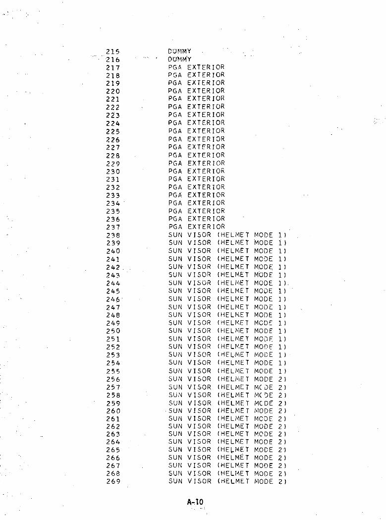
215216217218219220221222223224225226227228229230231232233234235236237238239240241242 .243244245246247248249250251252253254255256257258259260261262263264265266267268269
DUMMY - ' " . - . -DUMMYPGA EXTERIORPGA EXTERIORPGA EXTERIORPGA EXTERIORPGA EXTERIORPGA EXTERIORPGA EXTERIORPGA EXTERIORPGA EXTERIORPGA EXTERIORPGA EXTERIORPGA EXTERIORPGA EXTERIORPGA EXTERIORPGA EXTERIORPGA EXTERIORPGA EXTERIORPGA EXTERIORPGA EXTERIORPGA EXTERIORPGASUNSUNSUNSUNSUN-SUNSUNSUNSUNSUNSUNSUNSUNSUNSUNSUNSUNSUNSUNSUNSUNSUNSUNSUNSUNSUNSUNSUNSUNSUNSUNSUN
EXTERIVVVVVVVVVVVVVVVVVVVVVVVVVVVVVVVV
ISORIIIIIIIIIIIIIIII
SORSORSORSORSDRSORSORSORSORSORSORSORSORSORSORSORISORIIIIIIIIIIIIII
SORSORSORSORSORSORSORSORSORSORSORSORSORSOR
OR(HELME(HELME
TT
(HELMET(HELME(HELME(HELME(HELME(HELME(HELME(HELME(HELME(HELME(HELME(HELME(HELME(HELME(HELME(HELME(HELME(HELME(HELME(HELME(HELME(HELME(HELME(HELME(HELME(HELME(HELME
TTTTTTTTTTTTTTTTTTTTTTTTTT
(HELMET(HELME(HELME
TT
MODE'MODEMODEMODEMODEMODEMODEMODEMODEMODEMODEMODEMODEMODEMODEMODEMODEMODEMODEMC DEMCDEMODEMODEMCDEMODEMCDEMODEMODEMODEMODEMODEMODE
1 )11111111111 )1 )1 )1 )1 )1 )1 )2)2)2)2)2)2 )2 )2 )2)2)2 )2)2)2)
A-.10
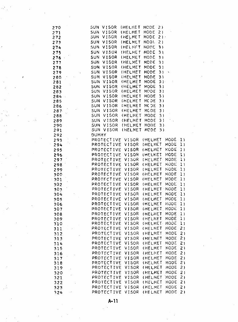
27027127227327427527627727827928028128228328428528628728828929029129229329429529629729829930030130230?304305306307308309310311312313314315316317318319320321322323324
SUN VISORSUN VISORSUN VISORSUN VISORSUN VISORSUN VISORSUN VISORSUN VISORSUN VISORSUN VISORSUN VISORSUN VISORSUN VISORSUN VISORSUN VISORSUN VISORSUN VISORSUN VISORSUN VISORSUN VISORSUN VISORSUN VISORDUMMYPROTECTIVEPROTECT IVEPROTECTIVEPROTECTIVEPROTECTIVEPROTECTIVEPROTECTIVEPROTECTIVEPROTECTIVEPROTECTIVEPROTECTIVEPROTECTIVEPROTECTIVEPROTECTIVEPROTECTIVEPROTECTIVEPROTECTIVEPROTECTIVEPROTECTIVEPROTECTIVEPROTECTIVEPROTECTIVEPROTECTIVEPROTECTIVEPROTECTIVEPROTECTIVEPROTECTIVEPROTECTIVEPROTECTIVEPROTECTIVEPROTECTIVEPROTECTIVE
HELMET(HELMET(HELMET(HELMET((((((((((((((((((
HELMFTHELMETHELMETHELMETHELMETHELMETHELMETHELMETHELMETHELMETHELMETHELMETHELMETHELMETHELMETHELMETHELMETHELMET
VISORVISORVISORVISORVISORVISORVISORVISORVISORVISORVISORVISORVISORVISORVISORVISORVISORVISORVISORVISORVISORVISOR-VISORVISORVISORVISORVISORVISORVISORVISORVISORVISOR
MCDE 2MODE 2MODE 2MODI- 2MOOT: 3MODE 3MODE 3MCDE 3MODE 3MODE 3MODE 3MODE 3MODE 3MODE 3MODE 3MC DE 3MCDE 3MCDE 3MODE 3MCDE 3MODE 3MODE 3
(HELMET(HELMET(HELMET(HELMET(HELMET(HELMET(HELMET(HELMET(HELMET(HELMET(HELMET(HELMET(HELMET(HELMET(HELMET(HELMET(HELMET(HELMET(HELMET(HELMET(HELMET(HELMET(HELMET(HELMET(HELMET(HELMET(HELMET(HELMET(HELMET(HELMET(HELMET(HELMET
)))))).))))))))))))))))
v
MODEMODEMODEMODEMODEMODEMODEMODEMODEMODEMODEMODEMODEMODEMODEMODEMODEMODEMODEMODEMODEMODEMODEMODEMODEMODEMODEMODEMODEMODEMODEMODE
1)1)1 )1)1 )1 )1 )1 )1 )1 )1111111122}2)2)2)2)2)2)2)212)2)2)2)
A-ll
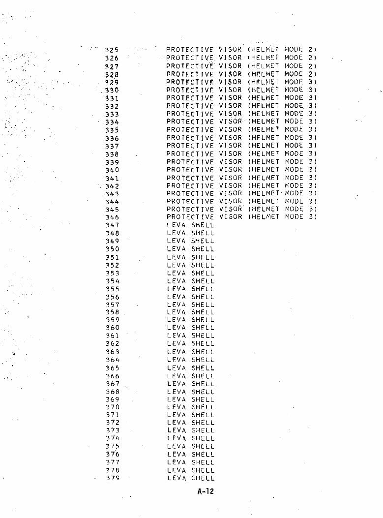
325326327328
331332333334335336337338339340341342343344345346347348349350351352353354355356357358359360361362363364365366367368369370371372373374375376377378379
PROTECTIVEPROTECTIVE,PROTECTIVEPROTECT IVEPROTECTIVEPROTECT tVEPROTECTIVEPROTECTIVEPROTECTIVEPROTECTIVEPROTECTIVEPROTECTIVEPROTECTIVEPROTECTIVEPROTECTIVEPROTECTIVEPROTECTIVEPROTECTIVEPROTECTIVEPROTECTIVEPROTECTIVEPROTECT IVELEVA SHELLLEVA SHELLLEVA SHELLLEVA SHELLLEVA SHELLLEVA SHELLLEVA SHELLLEVA SHELLLEVA SHELLLEVA SHELLLEVA SHELLLEVA SHELLLEVA SHELLLEVA SHELLLEVA SHELLLEVA SHELLLEVA SHELLLEVA SHELLLEVA SHELLLEVA SHELLLEVA SHELLLEVA SHELLLEVA SHELLLEVA SHELLLEVA SHELLLEVA SHELLLEVA SHELLLEVA. SHELLLEVA SHELLLEVA SHELLLEVA SHELLLEVA SHELLLEVA SHELL
VIVIVIVIVIVIVIVIVIVIVIVIVIVIVIVIVIVIVIVIVIVI
SORSORSORSORSORSORSORSORSORSORSORSORSORSORSORSORSORSORSORSORSOR'SOR
(HELMET(HELMET(HELMET(HELMET(HELMET(HELMET(HELMET(HELMET(HELMET(HELMET(HELMET(HELMET(HELMET(HELMET(HELMET(HELMET(HELMET(HELMET(HELMET(HELMET(HELMET(HELMET
MODEMODEMODEMO DCMODEMODEMODEMODE.MODEMODEMODtMODEMODEMODEMODEMODEMODEMODEMODEMOD'EMODEMODE
2222333333333333333333
A-12
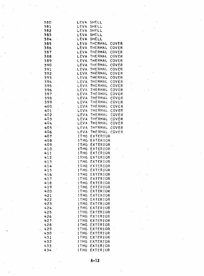
380381382383384385386387388389390391392393394395396397398399400401402403404405406407408409410411412413414415416417418419420421422423424425426427428429430431432433434
LEVALEVALEVALEVALEVALEVALEVALEVALEVALEVALEVALEVALEVALEVALEVALEVALEVALEVALEVALEVALEVALEVALEVALEVALEVALEVALEVAITMGITMGITMGITMGITMGITMGITMGITMGITMGITMGITMGITMGITMGITMGITMGITMGITMGITMGITMGITMGITMGITMGITMGITMGITMGITMGITMGITMG
SHELLSHELLSHELLSHELLSHELLTHERMAL COVERTHERMAL COVERTHERMAL COVERTHERMAL COVERTHERMAL COVERTHERMAL COVERTHERMAL COVERTHERMAL COVERTHERMAL COVERTHERMAL COVERTHERMAL COVERTHERMAL COVERTHERMAL COVERTHERMAL COVERTHERMAL COVERTHERMAL COVERTHERMAL COVERTHERMAL COVERTHERMAL COVERTHERMAL COVERTHERMAL COVERTHERMAL COVEREXTERIOREXTERIOREXTERIOREXTERIOREXTERIOREXTERIOREXTERIOREXTERIOREXTERIOREXTERIOREXTERIOREXTERIOREXTERIOREXTERIOREXTERIOREXTERIOREXTERIOREXTERIOREXTERIOREXTERIOREXTERIOREXTERIOREXTERIOREXTERIOREXTERIOREXTERIOREXTERIOREXTERIOR
A-13
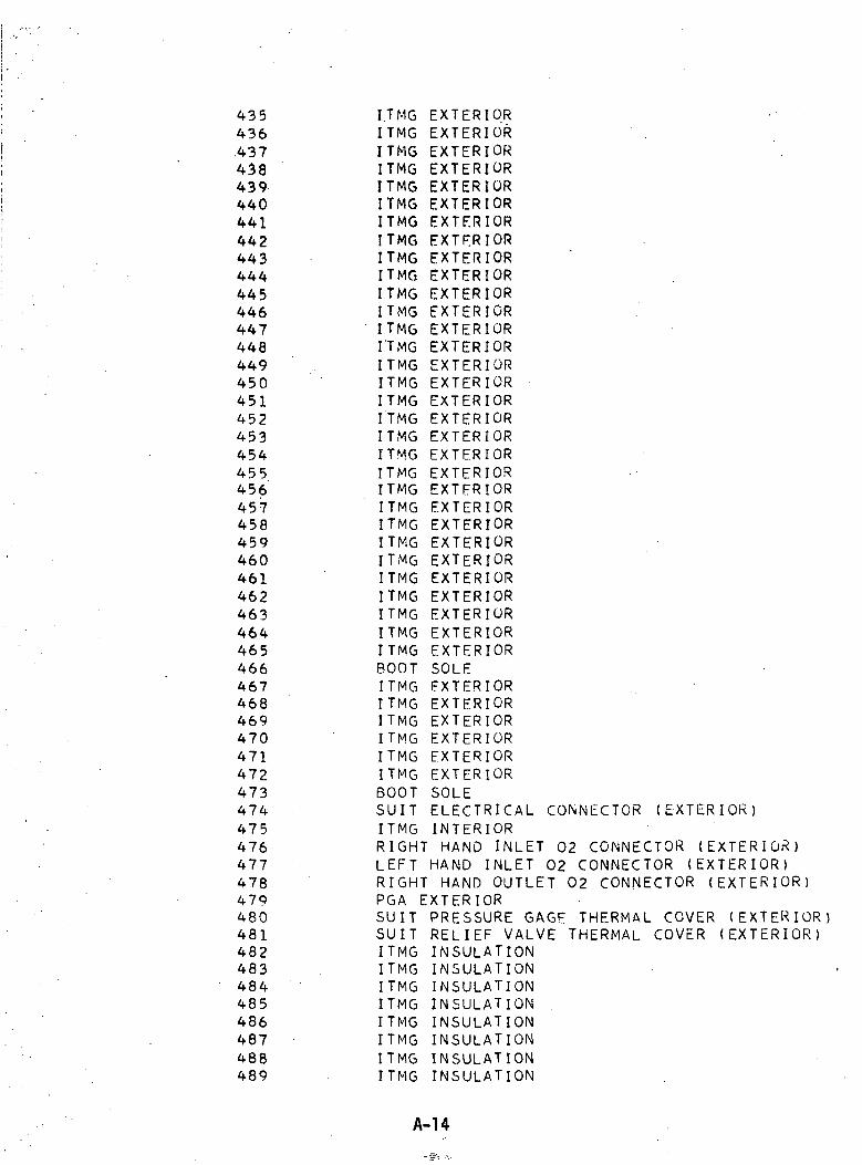
435436.437438439440441442443444445446447448449450451452453454455456457458459460461462463464465466467468469470471472473474475476477478479480481482483484485486487488489
I.TMG EXTERIOR •ITMG EXTERIORITMG EXTERIORITMG EXTERIORITMG EXTERIORITMG EXTERIORITMG EXTERIORITMG EXTERIORITMG EXTERIORITMG EXTERIORITMG EXTERIORITMG EXTERIORITMG EXTERIORI'TMG EXTERIORITMG EXTERIORITMG EXTERIORITMG EXTERIORITMG EXTERIORITMG EXTERIORITMG EXTERIORITMG EXTERIORITMG EXTERIORITMG EXTERIORITMG EXTERIORITMG EXTERIORITMG EXTERIORITMG EXTERIORITMG EXTERIORITMG EXTERIORITMG EXTERIORITMG EXTERIORBOOT SOLEITMG EXTERIORITMG EXTERIORITMG EXTERIORITMG EXTERIORITMG EXTERIORITMG EXTERIORBOOT SOLESUIT ELECTRICAL CONNECTOR (EXTERIOR)ITMG INTERIORRIGHT HAND INLET 02 CONNECTOR (EXTERIOR)LEFT HAND INLET 02 CONNECTOR (EXTERIOR)RIGHT HAND OUTLET 02 CONNECTOR (EXTERIOR)PGA EXTERIORSUIT PRESSURE GAGE THERMAL COVER (EXTERIOR)SUIT RELIEF VALVE THERMAL COVER (EXTERIOR)ITMG INSULATIONITMG INSULATIONITMG INSULATIONITMG INSULATIONITMG INSULATIONITMG INSULATIONITMG INSULATIONITMG INSULATION
A-14
490 ITMG INSULATION491 ITMG INSULATION492 ITMG INSULATION493 ITMG INSULATION494 ITMG INSULATION495 ITMG INSULATION49f> ITMG INSULATION497 ITMG INSULATION498 ITMG INSULATION499 ITMG INSULATION500 . ITMG INSULATION501 • '• ' : ITMG. INSULATHDH502 ITMG INSULATION503 ITMG INSULATION504 • ITMG INSULATION505 ITMG INSULATION506 ITMG INSULATION50? ITMG INSULATION508 ITMG INSULATION509 . ITMG INSULATION510 ITMG INSULATION511 ITMG INSULATION512 • '' • ITMG INSULATION513 ITMG INSULATION514 ITMG INSULATION515 ITMG INSULATION516 ' ITMG INSULATION517 . ITMG INSULATION518 ITMG INSULATION519 ITMG INSULATION520 ITMG INSULATION521 . ITMG INSULATION522 ITMG INSULATION523 ITMG INSULATION524 ITMG INSULATION5.25 ITMG INSULATION526 ITMG INSULATION527 ITMG INSULATION528 ITMG INSULATION529 ITMG INSULATION530 . ITMG INSULATION
:531 ITMG INSULATION532 ITMG INSULATION533 ITMG INSULATION534 . ITMG INSULATION535 ITMG INSULATION536 ITMG INSULATION537 ITMG INSULATION538 ITMG INSULATION539 ITMG INSULATION540 ITMG INSULATION541 ITMG INSULATION542 ITMG INSULATION543 ITMG INSULATION544 ITMG INSULATION
A-15
545546347548549550551552553554555556557558559560561562563564565566567568569570571572573574575576577578579580581582583584585586587588589590591592593594595596597598599
ITMG INSULATIONITMG INSULATIONITMG INSULATIONITMG INSULATIONITMG INTERIORITMG INTERIORITMG INTERIORITMG INTERIORITMG INTERIORITMG INTERIORITMG -INTERIORITMG INTERIORITMG INTERIORITMG INTERIORITMG INTERIORITMG INTERIORPGA EXTERIORPGA EXTERIORPGA EXTERIORPGA EXTERIORPGA EXTERIORPGA EXTERIORPGA EXTERIORPGA EXTERIORPGA EXTERIORPGA EXTERIORPGA EXTERIORPGA EXTERIORSUIT PRESSURE GAGE THERMAL COVERSUIT PRESSURE GAGE THERMAL COVERSUIT PRESSURE GAGES'UIT RELIEF VALVE THERMAL COVERSUIT RELIEF VALVE THERMAL COVERSUIT RELIEF VALVEOPS 02 UMBILICAL SHEATHOPS 02 UMBILICALOPS 02 UMBILICALOPS 02 UMBILICALOPS 02 UMBILICALOPS 02 UMBILICALOPS 02 UMBILICALOPS 02 UMBILICAL
02 UMBILICALMODULEMODULEMODULEMODULEMODULE
INSULATIONINTERIOR
INSULATIONINTERIOR
OPSCOMMANDCOMMANDCOMMANDCOMMANDCOMMANDSM SKINSM SKINSM SKINEPS RADIATOREPS RADIATOR
SHEATHSHEATHSHE ATHSHEATHSHEATHSHEATHSHEATHSHEATH
SKINSKINSKINSKINSKIN
BETWEEN EPSBETWEEN EPSBETWEEN EPS
PANELPANEL
EXTERIORINSULATIONINTERIOREXTERIORINSULATIONINTERIOREXTERIORINSULATIONINTERIOR
RADIATORSRADIATORSRADIATORS
EPSEPS
RADIATORRADIATOR
PANELPANEL
A-16

600601602603604605606607608 '609610611612613614615616617618619620'621622623624625626627628
. 629630631632633634635636637638639640641642643644645646647648649650651652653654
SMSMSMSMSMECSECS
SKINSKINSKINSKINSKINRADIATORRADIATOR
ABOVE ECSABOVE ECSSIM BAYABOVE ECSABOVE ECS
PANELPANEL
RADIATORRADIATOR
RADIATOKRADIATOR
ECS RADIATOR PANELECS RADIATOR PANELSM SKIN BELOW ECS R/D1ATOKSM SKIN BELOW ECS R/DIATORSM SKIN BELOW SIM BAYSM SKIN BELOW ECS RADIATORSM SKIN BELOW ECS RADIATORCOMPARTMENT 1COMPARTMENT 1FLOOR OF COMPARTMENT 2WALL OF COMPARTMENT 2UPPER BULKHEAD - COMPARTMENTSLANTED REAR BULKHEADWALL OF COMPARTMENT 2VERTICAL REAR BULKHEADCOMPARTMENT 3OPEN HATCH DOORHATCH OPENINGLMP IN HATCH OPENINGQUAD A THRUSTER SURFACE.QUAD A THRUSTER SURFACEQUAD A THRUSTER SURFACEQUAD A THRUSTER SURFACEQUAD B THRUSTER SURFACEQUAD B THRUSTER SURFACEQUAD B THRUSTER SURFACEQUAD B THRUSTER SURFACESUBSATELLITE BOXSUBSATELLITE BOXSUBSATELLITE BOXSUBSATELLITE BOXFOOT RESTRAINTPAN CAMERAPAN CAMERAPAN CAMERAPAN CAMERAPAN CAMERACOMMAND MODULE SKINCASSETTE* PANORAMIC CAMERACASSETTE, MAPPING CAMERARAILING
SUPPORTSUPPORTSUPPORTSUPPORTSUPPORT
- COMPARTMENT 2
- COMPARTMENT
LIFELIFELIFELIFELIFELIFELIFE
SUPPORTSUPPORT
UMSILICALUMBILIC ALUMBILICALUMBILICALUMBILICALUMBILICALUMBILICAL
INTERIORINTERIORINTERIORINTERIORINTERIORINTERIORINTERIOR
A-17
655656657658659660661662663664665666667668669670671672673674675676677678679680681682683684685686687688689690691692
LIFELIFELIFELIFELIFELIFELIFELIFELIFELIFELIFELIFELIFELIFELIFELIFELIFELIFELIFELIFELIFELIFELIFELIFELIFELIFELIFELIFELIFELIFELIFELIFELIFELIFELIFELIFELIFELIFE
SUPPORTSUPPORTSUPPORTSUPPORTSUPPORTSUPPORTSUPPORTSUPPORTSUPPORTSUPPORTSUPPORTSUPPORTSUPPORTSUPPORTSUPPORTSUPPORTSUPPORTSUPPORTSUPPORTSUPPORTSUPPORTSUPPORTSUPPORTSUPPORTSUPPORTSUPPORTSUPPORTSUPPORTSUPPORTSUPPORTSUPPORTSUPPORTSUPPORTSUPPORTSUPPORTSUPPORTSUPPORTSUPPORT
UMBILICALUMBILICALUMBILICALUMBILICALUMBILICALUMBILICALUMBILICALUMBILICALUMBILICALUMBILICALUMBILICALUMBILICALUMBILICALUMBILICALUMBILICALUMBILICALUMBILICALUMBILICALUMBILICALUMBILICALUMBILICALUMBILICALUMBILICALUMBILICALUMBILICALUMBILICALUMBILICALUMBILICALUMBILICALUMBILICALUMBILICALUMBILICALUMBILICALUMBILICALUMBILICALUMBILICALUMBILICALUMBILICAL
INTERIORINTERIORINTERIORINTERIORINTERIORINTERIORINTERIORINTERIORINSULATIONINSULATIONINSULATIONINSULATIONINSULATIONINSULATIONINSULATIONINSULATIONINSULATIONINSULATIONINSULATIONINSULATIONINSULATIONINSULATIONINSULATIONEXTERIOREXTERIOREXTERIOREXTERIOREXTERIOREXTERIOREXTERIOREXTERIOREXTERIOREXTERIOREXTERIOREXTERIOREXTERIOREXTERIOREXTERIOR
A-18