Embed Size (px)
Citation preview
Report
IN-015/2019
______________________________
Incident involving a BOEING B-737-
524, registration LY-KLJ, at the Getafe
Air Base (Madrid) on 5 April 2019
Please note that this report is not presented in its final layout and therefore it could include minor errors or need type corrections, but
not related to its content. The final layout with its NIPO included (Identification Number for Official Publications) will substitute the
present report when available.

IN-015/2019
Notice
This report is a technical document that reflects the point of view of the Civil Aviation
Accident and Incident Investigation Commission (CIAIAC) regarding the circumstances
of the accident object of the investigation, and its probable causes and consequences.
In accordance with the provisions in Article 5.4.1 of Annex 13 of the International Civil
Aviation Convention; and with articles 5.5 of Regulation (UE) nº 996/2010, of the
European Parliament and the Council, of 20 October 2010; Article 15 of Law 21/2003
on Air Safety and articles 1., 4. and 21.2 of Regulation 389/1998, this investigation is
exclusively of a technical nature, and its objective is the prevention of future civil
aviation accidents and incidents by issuing, if necessary, safety recommendations to
prevent from their reoccurrence. The investigation is not pointed to establish blame or
liability whatsoever, and it’s not prejudging the possible decision taken by the judicial
authorities. Therefore, and according to above norms and regulations, the investigation
was carried out using procedures not necessarily subject to the guarantees and rights
usually used for the evidences in a judicial process.
Consequently, any use of this report for purposes other than that of preventing future
accidents may lead to erroneous conclusions or interpretations.
This report was originally issued in Spanish. This English translation is provided for
information purposes only.
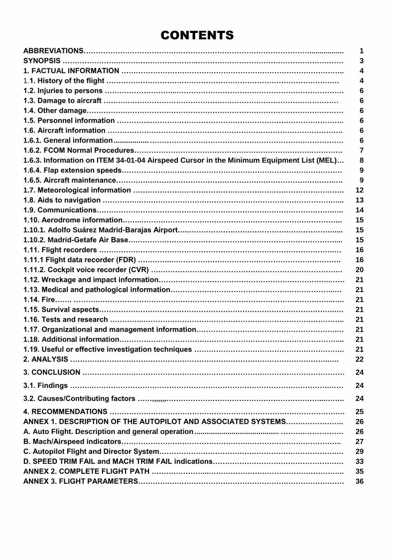
CONTENTS
ABBREVIATIONS…………………………………………………………………………………................. 1
SYNOPSIS ………………………………………………..…………………………………………………… 3
1. FACTUAL INFORMATION ……………………………………………………………………………….. 4
1.1. History of the flight …………………………………………………………………………………… 4
1.2. Injuries to persons ………………………...…………………………………………………………… 6
1.3. Damage to aircraft ……….…………………………………………………………………………… 6
1.4. Other damage…………….……………………………………………………………………………… 6
1.5. Personnel information …………..…………………………………………………………………….. 6
1.6. Aircraft information ……………………………………………………………………………………. 6
1.6.1. General information ................. ………………………………………………………. ……………. 6
1.6.2. FCOM Normal Procedures……………………………………………………………….…………. 7
1.6.3. Information on ITEM 34-01-04 Airspeed Cursor in the Minimum Equipment List (MEL)… 8
1.6.4. Flap extension speeds……………….……………………………………………………………… 9
1.6.5. Aircraft maintenance……………..……………………………………………………………….…. 9
1.7. Meteorological information …………………………………………………………………………… 12
1.8. Aids to navigation …………….………………………………………………………………………... 13
1.9. Communications…………………………………………………………………………………….….. 14
1.10. Aerodrome information……..……………………………………………………………………….. 15
1.10.1. Adolfo Suárez Madrid-Barajas Airport…..…………………………………………………….... 15
1.10.2. Madrid-Getafe Air Base….……………………………………………………………………….... 15
1.11. Flight recorders …………………………………………………………………………………….… 16 1.11.1 Flight data recorder (FDR) …………..……………………………………………………………. 16 1.11.2. Cockpit voice recorder (CVR) ……………………………………………………………………. 20
1.12. Wreckage and impact information……………………………………………………………..…… 21
1.13. Medical and pathological information…………………………………………………………..… 21 1.14. Fire……. ……………………………………………………………………………………………..….. 21 1.15. Survival aspects……………………………………………………………………………………..… 21 1.16. Tests and research …………..……………………………………………………………………….. 21 1.17. Organizational and management information………………………………………………….… 21
1.18. Additional information………………………………………………………………………………... 21
1.19. Useful or effective investigation techniques …………………………………………………….. 21
2. ANALYSIS ……………………………………………………………………………………………..…. 22
3. CONCLUSION ……………………………………………………………………………………………… 24
3.1. Findings ……….…………………………………………………………………………………….…… 24
3.2. Causes/Contributing factors ……,,,,,,,………………………………………………………...…….. 24
4. RECOMMENDATIONS ……………………………………………………………………………………. 25
ANNEX 1. DESCRIPTION OF THE AUTOPILOT AND ASSOCIATED SYSTEMS…….…………….. 26
A. Auto Flight. Description and general operation ......................................... ………. ……………. 26
B. Mach/Airspeed indicators…………………………………………….………………….…………….. 27
C. Autopilot Flight and Director System…………………………………………………………………. 29
D. SPEED TRIM FAIL and MACH TRIM FAIL indications……………………………………………… 33
ANNEX 2. COMPLETE FLIGHT PATH …………………...……………………………………………….. 35
ANNEX 3. FLIGHT PARAMETERS………….……………………………………………………………… 36

IN-015/2019
1
ABBREVIATIONS
º ' " Sexagesimal degrees, minutes and seconds
A/C Aircraft
A/P Autopilot
ADI Altitude direction indicator
AESA Spain's National Aviation Safety Agency
AFCS Automatic flight control systems
AFDS Autopilot flight director system
AMM Aircraft Maintenance Manual
APP Approach control service
ATPL(A) Airline transport pilot license (airplane)
CAARL Civil Aviation Authority of the Republic of Lithuania
CAO Control Aéreo Operativo (coordinates civil-military traffic)
CPT Captain
CVR Cockpit voice recorder
CWS Control wheel steering
DFCS Digital flight control system
EADI Electronic attitude direction indicator
EHSI Electronic horizontal situation indicator
EYKA Kaunas Airport, Lithuania
Ft Feet
F/D Flight director
F/O First officer
FCC Flight control computer
FCOM Flight Crew Operating Manual
FDR Flight data recorder
FMA Flight mode annunciator
FMC Flight management computer
G/S Glide slope
GA Go around
GS Ground speed
h Hours
HDG SEL Heading select
HPa Hectopascals
IFR Instrument flight rules
ILS Instrument landing system
IR(A) Instrument rating (airplane)
Kg Kilograms
Km Kilometers
Kt Knots
L Left
Lb Pounds
LEGT Madrid Getafe Air Base
LEMD Adolfo Suárez Madrid Barajas Airport
LNAV Lateral navigation
LOC ILS localizer

IN-015/2019
2
m Meters
MCP Mode control panel
MEL Minimum equipment list
METAR Meteorological aerodrome report
N North
PN Part number
QNH Altimeter sub-scale setting to obtain elevation when on the ground (Query
Nautical Height)
R Right
RA Radio altimeter
RDMI Radio distance magnetic indicator
Sn Serial number
TAFOR Terminal aerodrome forecast
TAS True Airspeed
TCAS Traffic collision avoidance system
TLB Technical log book
TMA Maintenance technician
TO Takeoff
TO/GA Takeoff /Go around
TWR Tower
TWE GE Getafe tower
UTC Universal coordinated time
VFR Visual flight rules
VMO Maximum operating speed
VNAV Vertical navigation
VOR Very high frequency omnidirectional range
W West

IN-015/2019
3
SYNOPSIS
Owner and Operator: UAB KLASEJET
Aircraft: BOEING B-737-524, registration LY-KLJ
Date and time of incident: 5 April 2019 at 14:54 (local time1)
Site of incident: Getafe Air Base (Madrid)
Persons on board: 65 (uninjured)
Flight rules: IFR
Type of flight: Commercial air transport. Landing.
Date of approval: 26 February 2020
Summary of event:
On 5 April 2019, a BOEING B-737-524 aircraft, registration LY-KLJ, took off from
the Adolfo Suárez Madrid Barajas Airport (LEMD) en route to the Kaunas Airport (EYKA)
in Lithuania.
It took off from runway 14L, with the captain’s autopilot inoperative, and during the
climb, the first officer’s autopilot also became inoperative, so the crew decided to return to
the departure airport without assistance from the automated systems.
After doing two go-arounds on runway 18L in adverse weather conditions, the crew
declared an emergency and the aircraft was diverted by air traffic control to the Getafe Air
Base (LEGT), in Madrid, where the aircraft landed on runway 23.
There were no injuries and the aircraft was not damaged.
The CIAIAC became aware of the event on 9 April and immediately contacted the
operator to collect information. The next day, and in light of the data obtained, an
investigation was opened and a lead investigator was appointed. One day later, the flight
recorders were retrieved. The operator had sequestered them on the day of the incident
but did not protect the information they contained, since the CVR recordings were
unavailable.
The investigation has determined that the incident was caused by the problems the
crew had operating the aircraft in instrument conditions following the loss of the aircraft’s
two automatic flight control systems.
1 Unless otherwise specified, all times in this report are local. To obtain UTC, subtract two hours from local time.

IN-015/2019
4
1. FACTUAL INFORMATION
1.1. History of the flight
On 5 April 2019, the crew of a BOEING B-737-524 aircraft, registration LY-KLJ,
was preparing for a planned flight from the Adolfo Suárez Madrid Barajas Airport (LEMD)
to the Kaunas Airport (EYKA) in Lithuania.
During the pre-flight inspection, they identified a fault in the captain’s automatic
flight system, so both pilots, with help from a company engineer, reviewed the Minimum
Equipment List (MEL) and verified that it allowed dispatching the aircraft with this
equipment inoperative.
They decided to proceed with the flight and after receiving the relevant clearance,
took off from runway 14L at 14:15:26.
During the climb, several faults occurred with the first officer’s automatic flight
system, which eventually became inoperative at 14:17:32, so the crew decided to return to
the departure airport while flying without assistance from the automatic flight systems.
Spain’s air traffic control manager, ENAIRE, reported that shortly after takeoff, the
crew declared an emergency but did not report the exact nature of their problem.
At 14:20, the operations supervisor informed the approach controller that he was
transferring him an aircraft that had just taken off from Madrid-Barajas whose crew had
declared an emergency and wanted to return to the airport.
Based on information provided by the controller, he cleared the runway 18R
localizer by diverting two aircraft, AC/1 and AC/2, which were on approach to this runway.
He also instructed them to adjust their speeds to maintain the required separation as
much as possible, both to each other and to those that were already positioned at the
localizer.
The traffic that declared an emergency did not lower its speed properly and
crossed the two localizers at 250 kt behind a third aircraft, different from the two
mentioned above, A/C 3.
The controller then corrected the approach vector he had initially provided so that
the aircraft could intercept the localizer for runway 18L (180º heading).
The crew ended up going around at 14:23:10.
The controller asked if they had problems with the speed, since he did not know
the nature of their emergency, but the crew again requested vectors to land.
Because of its position, the aircraft had to climb to maintain the minimum altitude,
but the controller saw that it was not climbing.
He could not turn it toward Casas de Uceda because there were aircraft at the
runway 18R localizer and it would have had to continue toward heading 360º to try to
intercept it from behind.
Twice he informed the crew that they were below minimums and instructed them to
climb, but they did not carry out this instruction, since the aircraft was at 4,400 ft and
entering an area where the minimum was 6,700 ft.

IN-015/2019
5
It turned to 220º at 220 kt and positioned itself behind A/C 2, which was at the
other localizer.
It managed to intercept the localizer 11 NM out, at an altitude of 4,300 ft and a
speed of 170 kt.
At 8 NM out, it had not acquired visual contact with the runway. Its speed was 150
kt.
It remained at the localizer, and the controller transferred the aircraft to a colleague
who was on the final approach sequence (TWR 118.680) just before the aircraft reached a
distance of 4 NM from the DME.
At a distance of 2.5 NM DME, it changed localizers and the controllers realized
that it had gone around again. It was 14:33:58.
When the aircraft declared the emergency, the airport activated the local alert and
the airport firefighters were standing by to respond to any situation during the landing on
runway 18L.
After two failed landing attempts, the aircraft was diverted by air traffic control to
the Getafe Air Base (LEGT) in Madrid, where it landed on runway 23 at 14:53.
There were no injuries and the aircraft was not damaged.
At Madrid-Barajas, the runway from which the aircraft had taken off was checked
at 14:29. No foreign debris was found.
Figure 1. Photo of the aircraft at the air base

IN-015/2019
6
1.2. Injuries to persons
Injuries Fatal Serious Minor/None
Crew 8
Passengers 57
Others
1.3. Damage to aircraft
The aircraft landed undamaged.
1.4. Other damage
None.
1.5. Personnel information
The 56-year old pilot had an airline transport pilot license, ATPL(A), issued by the
Civil Aviation Authority of Lithuania (Civilinés Aviacijos Administracija Lietuvos Respublika
- CAALR) on 6 February 2006.
He had a B-737 300-900 type rating, an EMBRAER 170 type rating, an instrument
rating, IR(A), and a type rating instructor, TRI(A), for the B-737 300-900. He had an
English level of 4.
His license, ratings and medical certificate were all valid.
At the time of the incident, he had a total of 13,598 flight hours, of which 4,309 had
been on the type, all of them as pilot in command.
The 34-year old first officer had an airline transport pilot license, ATPL(A), issued
by the Civil Aviation Authority of Lithuania (CAALR) on 2 December 2016.
He had a B-737 300-900 type rating and an instrument rating, IR(A). He had an
English level of 4.
His license, ratings and medical certificate were all valid.
At the time of the incident, he had a total of 2,260 flight hours, of which 2,000 had
been on the type.
1.6. Aircraft information
1.6.1. General information
The Boeing B-737-524 is a transport airplane with a wingspan of 28.9 m, a length
of 33.1 m and a total height of 11.13 m.
Its empty weight is 31,500 kg (69,445 lb) and its maximum takeoff weight is 70,080
kg (154,500 lb).
The incident aircraft, registration LY-KLJ, had serial number 28923 and a valid
certificate of airworthiness, number 2022, issued by the Lithuanian Civil Aviation Authority
on 26 June 2017. It was valid until 25 June 2019.
It was outfitted with two CFM-56-3C1 engines.
The aircraft’s technical logbook listed the most recent maintenance tasks, done on
the day of the incident, and the deferred items.

IN-015/2019
7
Preflight Procedure – First Officer The first officer normally does this procedure.
Mode control panel ............................................................................Set COURSE(S) ...........................................................................Set FLIGHT DIRECTOR switch ...................................................ON Move the switch for the pilot flying to ON first.
Flight instruments ..........................................................................Check Set the altimeter.
Airspeed cursor control ........................................................ Push Verify that the flight instrument indications are correct. Verify that only these flags are shown: • TCAS OFF • expected RDMI flags Verify that the flight mode annunciations are correct: • autothrottle mode is blank • attitude (pitch) mode is blank • roll mode is blank • AFDS status is FD
Preflight Procedure – Captain The captain normally does this procedure.
Mode control panel ...............................................................................Set COURSE(S) ..............................................................................Set FLIGHT DIRECTOR switch .......................................................ON Move the switch for the pilot flying to ON first
Flight instruments ..............................................................................Check Set the altimeter. Airspeed cursor control ...........................................................Push Verify that the flight instrument indications are correct. Verify that only these flags are shown: • TCAS OFF • expected RDMI flags Verify that the flight mode annunciations are correct: • autothrottle mode is blank • attitude (pitch) mode is blank • roll mode is blank • AFDS status is FD
Before Taxi Procedure Recall ......................................................................... Check C, F/O Verify that all system annunciator panel lights illuminate and then extinguish.
1.6.2. Normal procedures in the FCOM
The FCOM contains the following in its Normal Procedures:
The same procedure also specifies that during the pre-flight procedure, both the
captain and first officer have to place the F/D switches in ON, placing the F/D for the PF in
the ON position first.
At this time, the crew also have to confirm that the airspeed cursor control is in the
pushed position and verify that the flight instrument indications are correct, including the
flags and flight mode annunciators.
Before taxiing, both pilots, the captain and first officer, check the recall function of
the master caution light and verify that all the annunciator panel lights illuminate and then
extinguish.

IN-015/2019
8
A portion of the takeoff procedure contained in the B737 500 FCOM is provided
below.
The FCOM, in the limitations section, states not to select the autopilot during
takeoff when below 1,000 ft AGL.
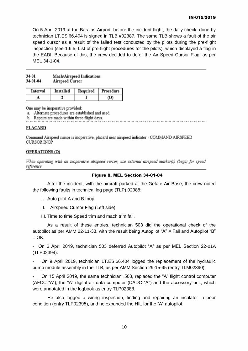
1.6.3. Information on ITEM 34-01-04, Airspeed Cursor, in the Minimum Equipment
List (MEL)
The Minimum Equipment List (MEL) has a section, Mach/Airspeed indications
Airspeed cursor, the contents of which are described below:
Based on the above, only one of the two airspeed cursors installed on the airplane
is required to be operative to dispatch the airplane, as long as it is repaired within three
days and alternate procedures are established and used.
The operating procedure associated with it specifies that the speed bugs be used
as a speed reference.
34-01 Mach/Airspeed Indications 34-01-04 Airspeed Cursor
Interval Installed Required Procedure
A 2 1 (O)
One may be inoperative provided: a. Alternate procedures are established and used. b. Repairs are made within three flight days.
PLACARD Command Airspeed cursor is inoperative, placard near airspeed indicator - COMMAND AIRSPEED CURSOR INOP OPERATIONS (O) When operating with an inoperative airspeed cursor, use external airspeed marker(s) (bugs) for speed reference.
Take-off Procedure
Pilot Flying Pilot Monitoring
Above 400 feet radio altitude, call for a roll mode as needed
Select and verify the roll mode
At thrust reduction height call “SET CLIMB THRUST”
Push the N1 switch
Verify that climb thrust is set
After flap and slat retraction call “VNAV”
Push the VNAV switch
Engage the autopilot when above the minimum altitude for autopilot engagement

IN-015/2019
9
1.6.4. Flap extension speeds
Below is an extract from the B 737 500 FCOM containing the flap extension
speeds.
1.6.5. Aircraft maintenance
A review of the aircraft’s technical logbook (TLB) since the day of the incident
showed that the maintenance tasks on it were performed by six different maintenance
technicians, identified in the TLB as follows:
The maintenance done and the entries in the TLB are described below:
Figure 7. Flap extension speeds
IN-015/2019
10
On 5 April 2019 at the Barajas Airport, before the incident flight, the daily check, done by
technician LT.ES.66.404 is signed in TLB #02387. The same TLB shows a fault of the air
speed cursor as a result of the failed test conducted by the pilots during the pre-flight
inspection (see 1.6.5, List of pre-flight procedures for the pilots), which displayed a flag in
the EADI. Because of this, the crew decided to defer the Air Speed Cursor Flag, as per
MEL 34-1-04.
After the incident, with the aircraft parked at the Getafe Air Base, the crew noted
the following faults in technical log page (TLP) 02388:
I. Auto pilot A and B Inop.
II. Airspeed Cursor Flag (Left side)
III. Time to time Speed trim and mach trim fail.
As a result of these entries, technician 503 did the operational check of the
autopilot as per AMM 22-11-33, with the result being Autopilot “A” = Fail and Autopilot “B”
= OK.
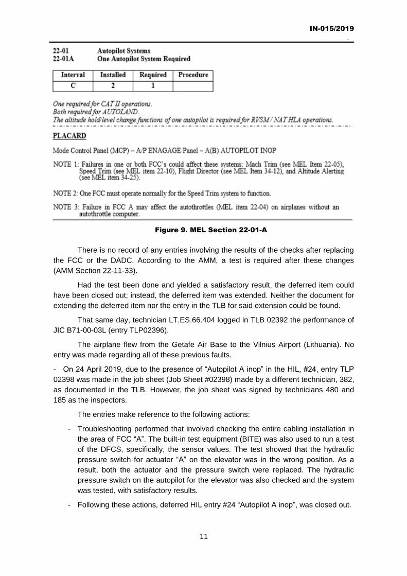
- On 6 April 2019, technician 503 deferred Autopilot “A” as per MEL Section 22-01A
(TLP02394).
- On 9 April 2019, technician LT.ES.66.404 logged the replacement of the hydraulic
pump module assembly in the TLB, as per AMM Section 29-15-95 (entry TLM02390).
- On 15 April 2019, the same technician, 503, replaced the “A” flight control computer
(AFCC “A”), the “A” digital air data computer (DADC “A”) and the accessory unit, which
were annotated in the logbook as entry TLP02388.
He also logged a wiring inspection, finding and repairing an insulator in poor
condition (entry TLP02395), and he expanded the HIL for the “A” autopilot.
Figure 8. MEL Section 34-01-04
IN-015/2019
11
There is no record of any entries involving the results of the checks after replacing
the FCC or the DADC. According to the AMM, a test is required after these changes
(AMM Section 22-11-33).
Had the test been done and yielded a satisfactory result, the deferred item could
have been closed out; instead, the deferred item was extended. Neither the document for
extending the deferred item nor the entry in the TLB for said extension could be found.
That same day, technician LT.ES.66.404 logged in TLB 02392 the performance of
JIC B71-00-03L (entry TLP02396).
The airplane flew from the Getafe Air Base to the Vilnius Airport (Lithuania). No
entry was made regarding all of these previous faults.
- On 24 April 2019, due to the presence of “Autopilot A inop” in the HIL, #24, entry TLP
02398 was made in the job sheet (Job Sheet #02398) made by a different technician, 382,
as documented in the TLB. However, the job sheet was signed by technicians 480 and
185 as the inspectors.
The entries make reference to the following actions:
- Troubleshooting performed that involved checking the entire cabling installation in
the area of FCC “A”. The built-in test equipment (BITE) was also used to run a test
of the DFCS, specifically, the sensor values. The test showed that the hydraulic
pressure switch for actuator “A” on the elevator was in the wrong position. As a
result, both the actuator and the pressure switch were replaced. The hydraulic
pressure switch on the autopilot for the elevator was also checked and the system
was tested, with satisfactory results.
- Following these actions, deferred HIL entry #24 “Autopilot A inop”, was closed out.
Figure 9. MEL Section 22-01-A

IN-015/2019
12
- On 24 April 2019, a test flight was conducted (entry TLP02400) by the same captain
from the incident flight, who noted the following:
- “DURING CLIMB APR. FL240 LOST OF EADI ON LH (BECOMES BLANK). AFTER
4 s POWER RESTORES AUTOMATICALLY ON EADI, EHSI. AUTOPILOT, FLIGHT DIR,
AUTOTHROTLE DISCONNECTS AUTOMATICALLY. YAW DAMPR STAYS IN OFF”.
- Subsequently, another operator, technician 127, did troubleshooting as per AMM
34-22-00, which gave a “TEST FAIL SG”, as a result of which the #1 symbol generator
was replaced.
- The troubleshooting was continued and relays C801, R3, R41 and R349 were
replaced as per AMM 24-21-00. The AC generation system test was then performed
again, giving a satisfactory result.
As per BOEING’s recommendation, the inertial reference units (IRU) were replaced.
- On 20 April 2019, a test flight was carried out, with no faults being identified (entry TL).
1.7. Meteorological information
According to the meteorological information provided by Spain’s National Weather
Agency (AEMET), the general situation at low levels was dictated by a front that was
crossing the peninsula, which caused showers and some storms as it passed and during
the subsequent cold spell.
Remote sensing data and images showed an extensive area of clouds and
precipitation affecting Madrid, with winds gusting up to 25 kt. At the time of the incident,
there was heavy rain and abundant clouds, which reduced visibility considerably.
At the departure airport (Madrid Barajas), the forecast contained in the METAR
and TAFOR reports was as follows:
METAR COR LEMD 051130Z 16012KT 120V200 9999 BKN020 BKN040
08/05 Q0999 R88/CLRD// NOSIG=
This corrected METAR was issued at 11:30 UTC. It indicated that the prevailing
wind direction was from 160º, variable between 120º and 200º at 12 kt. Visibility was in
excess of 10 km and there were broken clouds between 2000 and 4000 ft.
The temperature was 8º C, the dew point 5º C and the QNH was 999 hPa.
METAR LEMD 051200Z 16014G24KT 110V190 9999 -RA BKN020 BKN040
09/06 Q0999 NOSIG=
The 12:00 UTC METAR called for winds predominantly from 160º, variable
between 110º and 190º at 4 kt, gusting to 14 kt. Visibility was in excess of 10 km. There
was rain and broken clouds between 2000 and 4000 ft.
The temperature was 9º C, the dew point 6º C and the QNH was 999 hPa.
.METAR LEMD 051230Z 23017KT 6000 2500S SHRA SCT020TCU BKN025
07/04 Q0999 NOSIG=
The 12:30 UTC METAR predicted winds predominantly from 230º at 17 kt. Visibility
was 6 km. There were squalls and rain, as well as scattered clouds at 2,000 ft, and broken
and towering cumulus clouds at 2,500 ft.

IN-015/2019
13
The temperature was 7º C, dew point 4º C, and QNH was 999 hPa.
TAF LEMD 051100Z 0512/0618 22010KT 9999 BKN030 TX11/0515Z
TN03/0606Z PROB40 TEMPO 0512/0519 22015G25KT TEMPO 0512/0520
4000 RA SHRA SCT030TCU PROB30 TEMPO 0512/0519 3000 TSRA
SCT040CB PROB30 TEMPO 0606/0618 4000 RA SHRA BKN012
SCT040TCU PROB40 TEMPO 0611/0618 22020G32KT PROB30 TEMPO
0612/0618 3000 TSRA SCT030CB=
The 11:00 UTC TAFOR predicted wind from 220º at 10 kt, visibility in excess of 10
km and broken clouds at 3,000 ft.
At the airport where it landed, the following METAR, SPECI and TAFOR reports
were issued at around the time of the landing:
METAR LEGT 051200Z 19012G22KT 7000 RA SCT012 BKN017 BKN035
08/06 Q0999=
The 12:00 UTC METAR predicted wind predominantly from 190º at 12 kt, gusting
to 22 kt. Visibility was in excess of 7 km, it was raining with scattered clouds at 1,200 ft
and broken clouds between 1,700 and 3,500 ft.
The temperature was 8º C, dew point 6º C, and QNH was 999 hPa.
SPECI LEGT 051208Z 22015G25KT 170V250 2500 +RA FEW007 BKN014
BKN017 06/03 Q0999=
The 12:09 UTC SPECI predicted wind predominantly from 220, variable between
170º and 250º, at 12 kt, gusting to 25 kt. Visibility was 2,500 m. It was raining with few
clouds at 700 ft and broken clouds between 1,400 and 1,700 ft.
The temperature was 6º C, dew point 3º C, and QNH was 999 hPa.
TAF LEGT 051100Z 0512/0521 23010KT 9999 BKN030 PROB30 TEMPO
0512/0519 23015G25KT TEMPO 0512/0521 4000 RA SHRA SCT040TCU
PROB30 TEMPO 0512/0519 3000 TSRA SCT040CB=
The 11:00 UTC TAFOR, which was valid from 12:00 UTC until 21:00 UTC,
forecasted wind from 230º at 10 kt. Visibility was in excess of 10 km, with broken clouds at
3,000 ft.
Wing gusts varying between 15 and 25 kt from 12:00 UTC until 19:00 UTC, rain
and showers, clouds at 4,000 ft, as well as cumulus and cumulonimbus clouds at that
same altitude.
1.8. Aids to navigation
Runway 18L at the Madrid-Barajas Airport has a category III ILS/DME that is
available 24 hours a day. It is at coordinates 40º 31’ 31.5” N - 003º 33’ 29.6” W, and its
DME is at an elevation of 585 m.
The Madrid-Getafe Airport has a VOR that broadcasts at a frequency of 112.050
MHz 24 hours a day. It is located at coordinates 40º 17’ 23.4” N – 003º 43’ 34.2” W, at an
elevation of 624 m.

IN-015/2019
14
It also has an NDB that broadcasts 24 hours a day on 421.0 MHz. It is located at
coordinates 40º 11’ 59.2” N – 003º 50’ 39.4” W.
For landings, it had a category I ILS for runway 23. It is also available 24 hours a
day, and its localizer is located at coordinates 40º18’ 12.7” N - 003º 42’ 40.7” W and
broadcasts on 338.8 MHz. It is at an elevation of 252 m.
1.9. Communications
A summary of the most relevant communications is provided below:
- At 14:39, the tower (TWR) at the Madrid-Barajas Airport contacted approach (APP)
to report there was a traffic with an unknown problem that had some
malfunctioning equipment and that had unsuccessfully attempted to land at
Madrid-Barajas. The TWR also asked APP about the visibility.
In the minutes that followed, they exchanged weather information and reported
they were going to send it to the Madrid-Getafe Airport.
- At 14:44, the TWR informed APP that the weather information had changed, and
that visibility was 10,000 m, and asked if it would be able to land at the Madrid-
Barajas Airport.
- At 14:45, there was a conversation between the TWR and CAO, in which the
former reported that it was holding, that it had requested the METAR but that the
landing airport was still unknown.
- At 14:46, APP spoke with the tower at the Getafe Airport (TWR GE) to report that
the airplane was flying at 270 kt, which was very high, and in a holding pattern.
TWR GE asked why it had not made an emergency landing at Madrid-Barajas,
and APP replied that the crew could not see the airport. APP reported it had all
traffic stopped, that they made the approach twice but did not want to land and that
the crew’s English was not good and they were unable to describe their
emergency.
- At 14:47, the TWR GE communicated with another aircraft and reported that
runway 23 was in use, with the wind from 260º at 13 kt.
- At 14:19, APP communicated with TWR GE to inform it that APP was going to
send it to Getafe to land on runway 23. TWR GE gave the go-ahead, asked about
the type of aircraft and then contacted the firefighters at the airport to inform them
of the emergency and the type of aircraft involved.
- At 14:51, there were several conversations between the Scene Director and the
firefighters at the Madrid Getafe Airport to prepare for the emergency.
- At 14:52, the TWR GE contacted the airplane to report the wind (250/14) and
cleared it to land on runway 23, which the crew acknowledged.
- At 14:54, the airplane landed and the firefighters were cleared to cross the runway
to take up a position close to the airplane.

IN-015/2019
15
1.10. Aerodrome information
1.10.1. Adolfo Suárez Madrid-Barajas Airport
According to information contained in ENAIRE’s Aeronautical Information
Publication (AIP), the Madrid-Barajas Airport is located 13 km northeast of the city and it is
a 4E2 airport, as per the ICAO categorization.
Its reference point is at an elevation of 609 m (1998 ft) and it has four pairwise
parallel runways, designated 18R/36L, 18L/36R, 14R/32L and 14L/32R.
When the airport is operating in a north configuration, the 36 runways are used for
takeoffs and the 32 runways for landings. When it is operating in a south configuration, the
14 runways are used for takeoffs and the 18 runways for landings.
The weather information office is open 24 hours.
1.10.2. Madrid Getafe Air Base
According to information contained in ENAIRE’s AIP, the Madrid Getafe Air Base
(LEGT) is a military airport that is located 15 km southwest of the city. Its reference point
is at coordinates 40º 17’ 39” N – 3º 43’ 25” W, at an elevation of 619 m.
It has one runway in a 5/23 orientation that is 2,477 m long and 60 m wide. The
aerodrome pattern is flown south of the runway.
It has a weather office that is open from 05:00 to 20:00 on Mondays, and from
05:00 to 19:00 on Fridays. The rest of the time, it is open as required by the needs of the
unit. It issues METAR reports every hour and TAFOR reports every 9 hours.
2 The number 4 means the airport has a minimum reference field length of 1,800 m, and the letter E means that the aircraft
operating must have a wingspan between 52 m and 65 m and outer main gear wheel span between 9 m and 14 m.
Figure 10. Profile of the runway at the Madrid Getafe Air Base

IN-015/2019
16
1.11. Flight recorders
The aircraft had a flight data recorder (FDR) and a cockpit voice recorder (CVR),
which were retrieved on 11 April 2019 from their respective locations at the rear of the
aircraft and downloaded at the CIAIAC laboratory.
1.11.1. Flight data recorder (FDR)
The FDR was an L3 FA 2100, with part number (PN) 2100-4043-00 and serial
number (SN) 000001514.
Once the data were extracted and converted into engineering units at the CIAIAC
laboratory, it was found that the engines were started at 13:58:17, and that the FDR
started recording at 13:58:29, the time when the right engine was started.
The airplane began moving at 14:01:39, and at 14:14:54, it began its takeoff roll on
runway 14L, going airborne at 14:15:26, with the intention of flying standard instrument
departure RBO1U, which contains waypoints MD050 on heading 143º, MD051 on heading
117º and RBO on heading 9º.
Figure 11. Relative positions of the Madrid Barajas and Getafe Air Base airports

IN-015/2019
17
Figure 12. SID RBO1U from runway 14 L
The left-hand flight director (F/D B) was on during the entire flight, while the right-
hand flight director (F/D A) was OFF during the entire flight.
The takeoff was performed with flaps 5 until 4,700 ft3. At a GS of 204 kt (CAS of
202 kt), the flaps were retracted
to 1º. They were fully retracted
at 4,200 ft, when its GS was 305
kt (CAS of 235 kt).
In the interval between
flaps 1º and retracted, the
aircraft began turns to the north
and then to the northwest, with
altitude changes between 4,000
and 5,000 ft.
At 14:15:31, the front
gear was retracted, and the
main gear was up at 14:15:33.
At 14:15:43, the lateral
navigation system (LNAV) was
engaged for 1 s, just as the
airplane as climbing through a
pressure altitude (PA) of 2,852
ft.
At 14:15:58, while
climbing through a PA of 3,400
ft, N1 mode was set on the
autothrottle (ATHR). The N1
compressor RPM reading went
from 94% to 92%. This mode
remained on until 14:17:32, at
which time the FDR indicates
that the ATHR was manually
disengaged.
At 14:16:02, while climbing through a PA of 3,500 ft, the FDR recorded an attempt
to engage the right-hand autopilot (AP B) in COMMAND (CMD) mode for 8 s. The FDR
did not record any other attempts to engage the autopilot during this phase.
The GS remained around 170 kt and the pitch around 18º up to a PA of 4,100 ft, at
14:16:14, at which point the pitch value decreased to between 8º and 10º. As the aircraft’s
nose lowered, the GS increased to 260 kt (CAS of 207 kt) at 14:16:50, with the aircraft at
a PA of 4,900 ft.
At 14:16:26, the FDR recorded MCP SPEED FCC engaged upon passing 4,384 ft
PA at a GS of 188 kt. At no time was AT MCP SPEED engaged. This means that the
3 Las altitudes están referidas a la altitud de presión.

IN-015/2019
18
speed that the flight control computer had selected was set in the mode control panel, but
not in the thrust lever.
At 14:16:50, the heading started to decrease, indicating turns to the north with
changes in altitude between 4,000 and 5,000 ft (most of the time, the aircraft remained
around 4,500 ft).
Starting at 14:17:58, coinciding with the start of the turn to the north, the pitch
angle was 3º up (ANU), with N1 ranging between 90% and 81%.
At 14:17:34, the GS peaked at 394 kt (CAS of 283 kt), the pitch angle recorded
negative values as high as -11º (nose down – AND) and there were negative changes in
altitude. At that point, the AT was disengaged and N1 was reduced to a value of 37%. The
GS started to decrease from its maximum of 410 kt (at 14:17:42) to 312 kt (14:18:14).
During this time period, the FDR recorded a value for GS of between 260 and 410
kt, remaining at around 300 kt most of the time.
The aircraft stayed on a northerly course until 14:21:22, when it began to turn left
to intercept the runway 18L localizer, but the turn was too wide, so the aircraft was unable
to properly intercept the localizer from the left side (as seen from the cockpit), which is
where the aircraft was coming from to later intercept it from the right side, at
approximately 14:23:10, when its altitude was 5,536 ft and its GS was 266 kt (CAS of 220
kt).
It then continued climbing until 14:23:36, reaching 5,964 ft with a GS of 268 kt on a
course of 176º. It had problems maintaining the correct altitude and position with respect
to the ILS localizer and the glide slope.
It started to descend, maintaining the descent rate and the same deviations from
the localizer and glide slope until 14:25:43, when it reached its minimum altitude of 3,296
ft. This may be considered as the point when it initiated the first go-around.
According to ATS, it turned to heading 110º at a GS of 276 kt.
It continued climbing while turning left and at 14:27:36, it steadied on course north
with a GS of 314 kt. It stayed on that course for 1:38 minutes while climbing, but not
continuously.
At 14:29:14, it started turning left while changing its altitude noticeably.
At 14:30:10, when it was at 4,989 ft at a GS of 272 kt on heading 279º, it started
climbing again, reaching 5,784 ft at 14:31:02 on a heading of 206º and a GS of 170 kt,
which is when the second approach to LEMD may be said to have started.
During the entire climb after the first landing attempt, the crew increased the angle
of the flaps, first to 5º and then to 10º, which is the position they were in when the second
descent was initiated.
At 14:33:03, the nose gear was down, and 2 s later the main gear was down.
At 14:36:51, it reached its minimum altitude of 2,604 ft and aborted the landing a
second time. Its heading was 203º and its GS was 176 kt. The crew was still having
problems maintaining the ILS localizer and glide slope. During the descent, the flaps were
lowered to 15º at first and then fully extended, equivalent to a deflection of 30º.
IN-015/2019
19
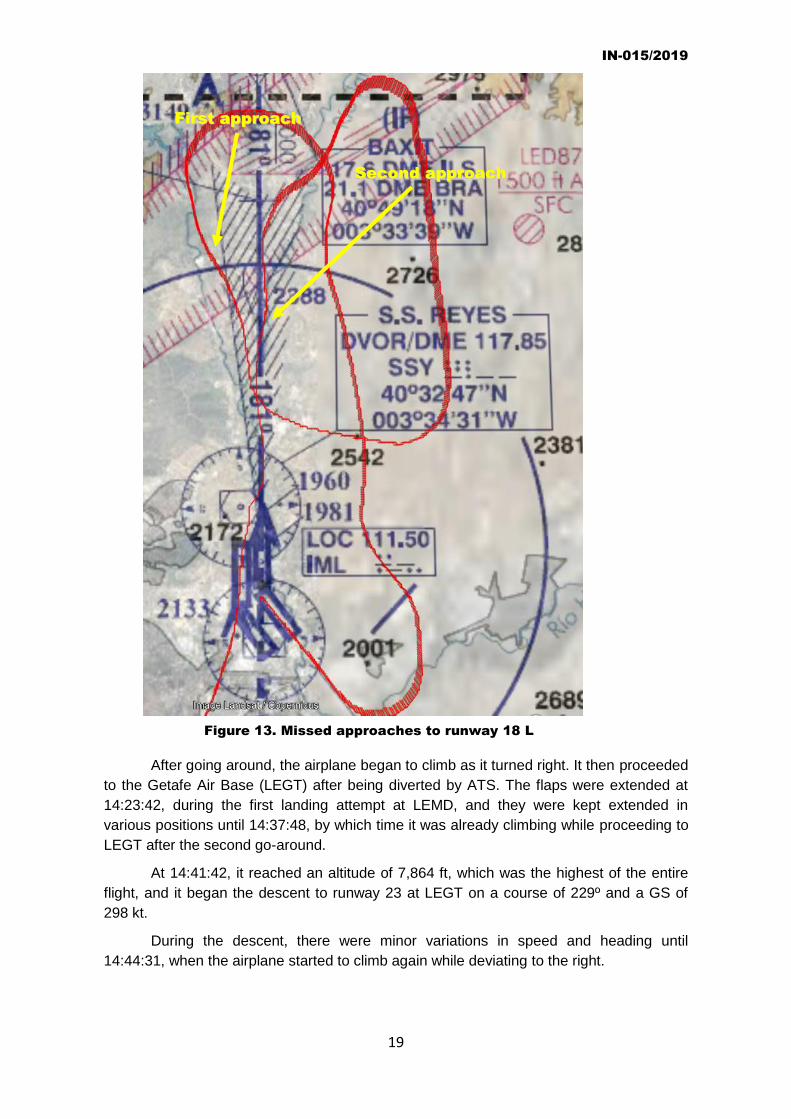
After going around, the airplane began to climb as it turned right. It then proceeded
to the Getafe Air Base (LEGT) after being diverted by ATS. The flaps were extended at
14:23:42, during the first landing attempt at LEMD, and they were kept extended in
various positions until 14:37:48, by which time it was already climbing while proceeding to
LEGT after the second go-around.
At 14:41:42, it reached an altitude of 7,864 ft, which was the highest of the entire
flight, and it began the descent to runway 23 at LEGT on a course of 229º and a GS of
298 kt.
During the descent, there were minor variations in speed and heading until
14:44:31, when the airplane started to climb again while deviating to the right.
Figure 13. Missed approaches to runway 18 L
FFiirrsstt aapppprrooaacchh
SSeeccoonndd aapppprrooaacchh

IN-015/2019
20
Between 14:44:31 and 14:47:09, the aircraft circled south of the runway in the
vicinity of the beacon designated GE, at an altitude between 6,688 and 6,440 ft. Its flaps
were not deployed.
It kept turning left while descending to fly the right downwind leg for runway 23.
The crew lowered the flaps at 14:49:24, first 1º, then 5º, 15º and 30º, which was
their position during the landing.
At 14:50:43, it was on the runway heading (229º) with a GS of 170 kt at an altitude
of 3,520 ft. It eventually landed at 14:52:28 with a GS of 160 kt (CAS of 145 kt).
1.11.2. Cockpit voice recorder (CVR)
The CVR, made by Honeywell, with PN 980-6022-001 and SN 04870, was also
removed from its housing on the same day as the FDR.
Four channels of audio were downloaded at the CIAIAC laboratory, but the
incident flight was not recorded. It is not known why the audio associated with the incident
was not recorded.
Figure 14. Approach to runway 23 at Getafe
AApppprrooaacchh ttoo GGeettaaffee

IN-015/2019
21
1.12. Wreckage and impact information
The landing at the Madrid-Getafe Air Base was normal. The aircraft was not
damaged and none of the persons on board was injured.
1.13 Medical and pathological information
Not applicable.
1.14. Fire
There was no fire.
1.15. Survival aspects
While attempting to land at the Madrid-Barajas Airport, a local emergency and alert
were declared and the firefighters were standing by on runway 18L to provide assistance.
At the Madrid-Getafe Airport, the firefighters were deployed to assist during the
landing on runway 23, and they aided in disembarking the passengers by setting up a
telescoping rising platform and a hydraulically-actuated boarding staircase, as well as a
ground power unit.
1.16. Tests and research
It was not necessary to conduct any special tests or research.
1.17 Organizational and management information
Not applicable.
1.18. Additional information
The operator wrote a report on its investigation into the event that contains
recommendations involving:
- Practicing manual flying, including in adverse weather scenarios, without help from
the automatic systems.
- A review of the decision-making and crew cooperation processes.
- Additional CRM training for the crew and incompatibility between the two members
that make up the same crew.
- Monitoring the defects involving the autopilot system.
1.19. Useful of effective investigation techniques
It was not necessary to use any special investigation techniques.
IN-015/2019
22
2. ANALYSIS
When analyzing this event, the first thing to note is the fact that having both
autopilots become inoperative did not prevent proceeding with the flight in instrument
conditions, since the instruments required to carry out a flight of these characteristics were
available to the crew at all times; namely, they had the artificial horizon, altimeter,
variometer, anemometer, compass, turn and bank indicator and the engine instruments
(intake pressure and engine pressure ratio).
The crewmembers had instrument flight ratings and, based on the information
gathered, had considerable experience, both in general and on the type.
In the case of the captain, he was a type rating instructor (TRI(A)), meaning he
was not only very familiar with the airplane, its systems and its operation, but he had to be
able to explain these concepts, that is, to convey them during training to other
crewmembers in an operational setting, and to other pilots in general in a training setting.
If the first officer was the pilot flying (PF), it was because the captain noticed that
the air speed cursor flag on his own side was inoperative, and since it is the captain who
has to know all the aircraft systems well, he might have thought that the flight computer
was affected. They therefore engaged the computer on the other side to do the flight.
An analysis of the data recorded on the FDR does not show any attempt to engage
the autopilot on the captain’s side (AP A). The flight director on that side (F/D A) was off
from the start of the flight, although it should have been on, since the F/D is independent
from the autopilot. The crew had set up the cockpit to have both the AP and F/D on the
first officer’s side be the master, meaning they were turned on first so that for both
systems, the ones on the right side provided the guidance. The AP were inoperative, but if
both F/D had been on, the indications provided would have been from the right side.
However, the data recorded in the FDR show that the F/D display on the left side
was off, meaning the captain did not have guidance from the F/D on his side.
The data recorded in the FDR clearly indicate that they had considerable problems
maintaining the basic flight parameters (altitude, speed, heading, etc.). This is most
obvious when analyzing the turns.
The bad weather conditions complicated the operation.
There was turbulence and significant cloud cover between 2,000 and 4,000 ft in
and around the Madrid-Barajas Airport. This prevented the crew from making a safe visual
approach, and they probably did not have the runway in sight.
After the second failed landing attempt, the aircraft was diverted to the Madrid-
Getafe Air Base, probably because ATS thought that a third attempt would entail delays
and safety risks for other traffic arriving at the Madrid-Barajas Airport, but not because the
weather conditions were clearly better at the Madrid-Getafe Airport. The clouds were just
as low, though perhaps not as dense on the surface, which helped with the landing.
Also worth noting is the communication made at 14:46 between approach (APP)
and the tower at the Getafe Air Base (TWR GE), in which APP reported that the crew did
not speak English well and were unable to clearly describe the emergency they were
experiencing.

IN-015/2019
23
Their English proficiency was rated as 4, which should have been sufficient to
correctly communicate the nature of the problem.
The problems maintaining the basic flight parameters due to the absence of
automatic control systems indicates that neither the decision making nor the cooperation
between the crew were adequate.
All of these aspects, which could be the subject of a safety recommendation, were
already noted by the Operator in its report on the event; as a result, no additional
recommendations are necessary.
The Operator also noted the need to track the defects associated with the autopilot
system.
IN-015/2019
24
3. CONCLUSIONS
3.1. Findings
- The aircraft took off from runway 14L at the Madrid Barajas Airport (LEMD).
- Its destination was the Kaunas Airport (EYKA) in Lithuania.
- On board were 2 pilots, 6 flight attendants and 57 passengers.
- The aircraft’s documentation was valid.
- The captain had a valid type rating instructor (TRI(A)) rating.
- Both pilots had an English level of 4 annotated in their respective licenses.
- The crew had valid licenses and medical certificates.
- The LH autopilot was inoperative before takeoff.
- The MEL allows operating with the LH autopilot inoperative.
- The RH autopilot was set up to be displayed at both positions.
- During the climb, the RH autopilot became inoperative.
- The crew decided to return to the departure airport when both autopilots became
inoperative.
- The RH flight director was set up to be displayed at both positions, but they did not
engage it.
- They were unable to clearly inform ATS what kind of malfunction they had.
- They made two unsuccessful landing attempts on runway 18L in IFR conditions.
- ATS diverted the flight to the Getafe Air Base (LEGT), where the weather conditions
were better.
- They landed at the Madrid Getafe Air Base on the first attempt.
3.2. Causes/Contributing factors
The investigation has determined that the incident was caused by the
problems the crew had operating the aircraft in instrument flight conditions after
losing both of the aircraft’s automatic flight systems.

IN-015/2019
25
4. RECOMMENDATIONS
None.
IN-015/2019
26
ANNEX 1. DESCRIPTION OF THE AUTOPILOT
A. (AUTO FLIGHT). General description and operation.
According to the AMM, the automatic flight control system (AFCS) in the B737 500
consists of three independent subsystems:
These systems provide control of the airplane and automatic stabilization about the
pitch and yaw axes.
The DFCS is a two-axis system (pitch and roll) that operates the elevators and
ailerons to automatically maintain altitude and indicated airspeed and to steer the
airplane, as well as to perform autolandings. The control functions also translate into flight
director commands, which are shown in the electronic attitude direction indicator (EADI)
displays of the pilots, thus providing command indications during manual operation or
allowing the pilots to monitor the operation of the autopilot.
The autothrust system maintains the Mach number or indicated airspeed during cruise
that was previously set, and it also maintains any previously selected engine thrust
settings, when performing takeoffs controlled by the flight director, or approaches and
landings controlled by the autopilot-flight director, by adjusting the engine thrust levers.
The SP300 digital flight control system (DFCS) installed on the B737 500 includes the
following functions:
• Autopilot
• Flight director
• Mach trim
• Speed trim
• Altitude alert
The two DFCS channels are independent, such that the flight director’s indications for
the captain are provided by “A” flight control computer (FCC A) and the flight director’s
indications for the first officer are provided by FCC B.
The purpose of the FCC is to receive inputs on the various modes and signals from
the sensors, process them and provide outputs for the control surfaces, namely the
ailerons, elevator and rudder. The two FCCs are identical and interchangeable.
The diagram below, which shows an outline of the digital flight control system, is taken
from the AMM.

IN-015/2019
27
Figure 2. Diagram of the digital flight control system in the AMM
B. MACH / AIRSPEED indicators
The pilots each receive data for the information on indicated airspeed, Mach number
and the maximum operating speed on their own air data computer through two
Mach/airspeed electronic indicators.
The speed cursor that is located on these indicators is a moving bug that indicates
the selected speed. It can be positioned automatically or manually, depending on how the
airspeed cursor control is set.
In automatic mode, it can be positioned through its associated flight control computer
(FCC) using the inputs to the flight management computer (FMC) or the speed selector on
the mode control panel (Autopilot Flight Director System – AFDS).

IN-015/2019
28
Each speed cursor can also be positioned manually.
The airspeed cursor control has two positions:
Pushed in to select automatic mode.
Pulled out to select manual mode.
The speed cursor flag is shown when, in automatic mode, the signal for the speed
cursor as determined by the AFDS FCC is not reliable.
Figure 3 shows an extract from the B-737 500 FCOM that highlights these three
elements in the Mach/airspeed indicator, namely the airspeed cursor control (#5), the
airspeed cursor (#6) and the airspeed cursor flag (#9).
Airspeed Cursor Control
If pushed in, it is in automatic mode and then the airspeed cursor is positioned by the
AFDS FCC.
If pulled out, it is in manual mode and the airspeed cursor is adjusted by turning the
knob.
Airspeed Cursor
Can be positioned manually or automatically depending on the position of the
airspeed cursor control.
Airspeed Cursor Flag
Figure 3. Airspeed indicator

IN-015/2019
29
In manual mode, it is retracted, and in automatic mode, it is visible when the
airspeed cursor signals determined by the AFDS FCC are not reliable.
C. Autopilot Flight and Director System.
The autopilot flight director system (AFDS) is a dual system consisting of two flight
control computers (FCC) and one mode control panel (MCP).
To operate the autopilot (A/P), the FCCs, identified as A and B, send control
signals to their respective pitch and roll hydraulic servos, which operate the flight controls
by way of two separate hydraulic systems. To operate the flight director (F/D), each FCC
positions the F/D bars in its respective ADI.
Autopilot Engagement Criteria
Each A/P can be engaged by pushing a separate CMD or command wheel steering
(CWS) engage switch. A/P engagement in CMD or CWS is inhibited unless no force is
being applied to the control wheel and the STAB TRIM AUTOPILOT cutout switch is in
NORMAL.
If the autopilot is engaged in CMD, with one or two flight directors (F/D) operating in
control mode and the F/D command bars are not centered to within approximately half of
the scale, the A/P is engaged automatically in CWS for pitch and roll and the F/D
command bars disappear.
Flight Director Display
Turning a F/D switch ON displays command bars on the respective pilot’s attitude
indicator if command pitch and roll modes are engaged. F/D commands operate in the
same command modes as the A/P except:
• the takeoff mode is a F/D only mode.
Figure 4. Photograph of the airspeed indicator
Airspeed cursor flag on the B737 500 LY-KLJ

IN-015/2019
30
• dual F/D guidance is available for single engine operation.
• the F/D has no landing flare capability. F/D command bars retract from view at
approximately 50 feet RA on an ILS approach.
Normally, FCC A drives the captain’s command bars and FCC B drives the first
officer’s command bars. With both F/D switches ON, the logic for both pilots’ F/D modes is
controlled by the master FCC, and both FMA displays show the same mode status.
The master FCC is indicated by illumination of the respective master (MA) F/D
indicator light. The master FCC is determined as follows:
• With neither A/P engaged in CMD, the FCC for the first F/D turned on is the
master.
• With the A/P engaged in CMD, its associated FCC is the master FCC, regardless
of which F/D is turned ON first.
• With both A/Ps engaged in CMD, the FCC for the first A/P in CMD is the master
FCC, regardless of which F/D is selected first
F/D modes are controlled directly from the respective FCC under certain conditions.
This independent F/D operation occurs when neither A/P is engaged in CMD, both F/D
switches are ON and one of the following mode conditions exists:
• APP mode engaged with LOC and G/S captured.
• GA mode engaged and below 400 feet RA.
• TO mode engaged and below 400 feet RA.
Independent F/D operation is indicated by illumination of both MA lights. When
independent operation terminates, the MA light extinguishes on the slaved side.
AFDS Status Annunciation
The following AFDS status annunciations are displayed in the A/P status display,
located on the EADI:
• CMD (one or both autopilots are engaged).
• FD (the F/D is ON and the autopilot is either OFF or engaged in CWS).
• CWS P (pitch mode engaged in CWS).
• CWS R (roll mode engaged in CWS).
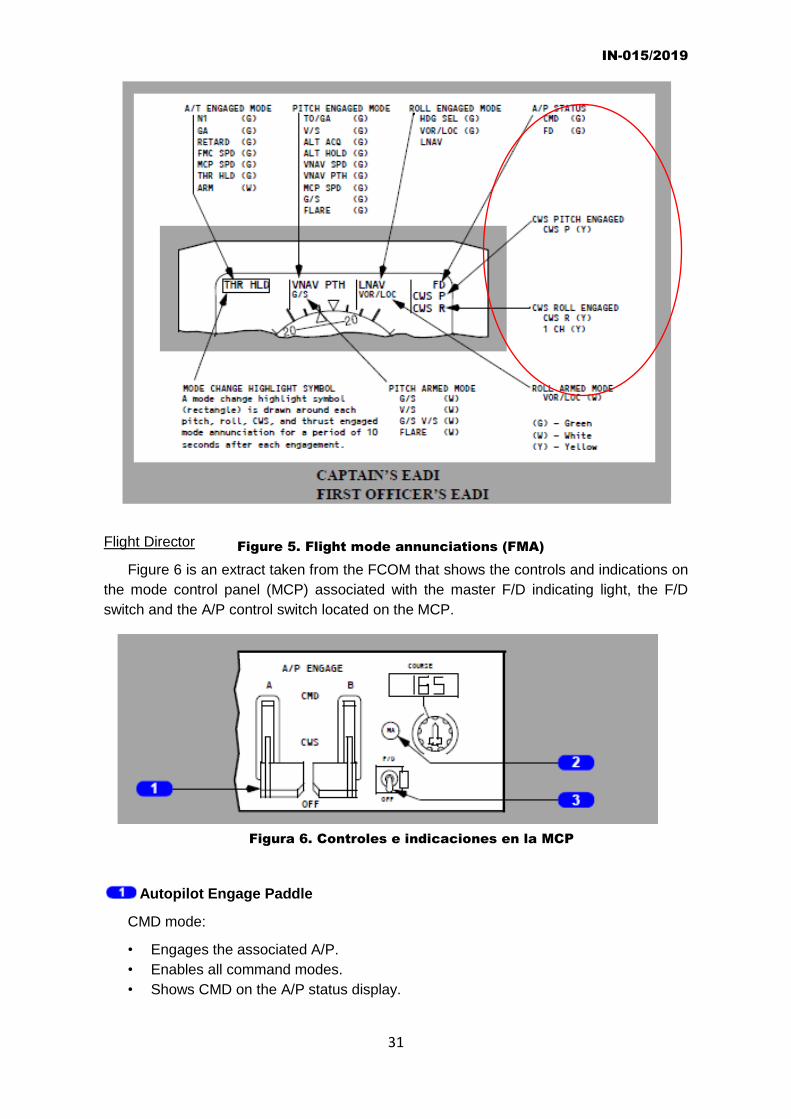
Figure 5, taken from the FCOM, shows the flight mode annunciations (FMA).
IN-015/2019
31
Flight Director
Figure 6 is an extract taken from the FCOM that shows the controls and indications on
the mode control panel (MCP) associated with the master F/D indicating light, the F/D
switch and the A/P control switch located on the MCP.
.
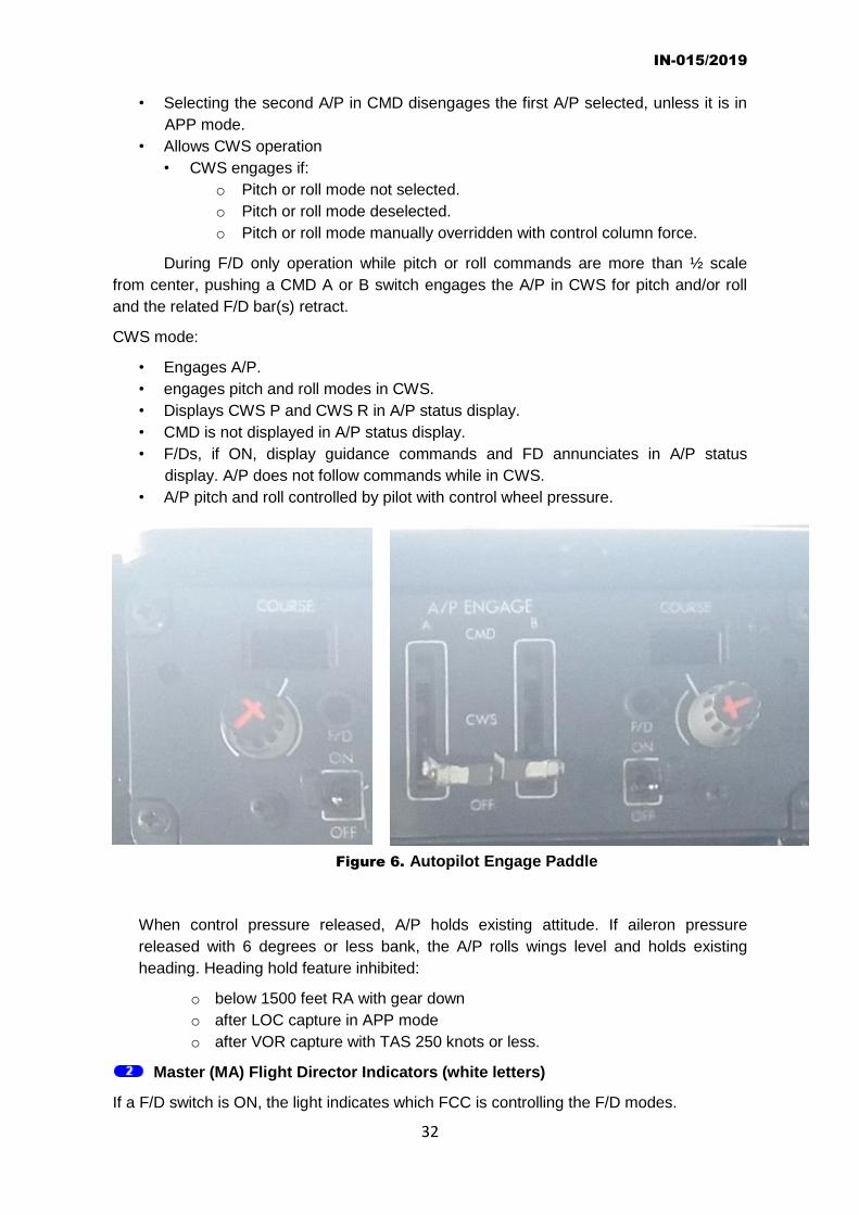
Autopilot Engage Paddle
CMD mode:
• Engages the associated A/P.
• Enables all command modes.
• Shows CMD on the A/P status display.
Figure 5. Flight mode annunciations (FMA)
Figura 6. Controles e indicaciones en la MCP
IN-015/2019
32
• Selecting the second A/P in CMD disengages the first A/P selected, unless it is in
APP mode.
• Allows CWS operation
• CWS engages if:
o Pitch or roll mode not selected.
o Pitch or roll mode deselected.
o Pitch or roll mode manually overridden with control column force.
During F/D only operation while pitch or roll commands are more than ½ scale
from center, pushing a CMD A or B switch engages the A/P in CWS for pitch and/or roll
and the related F/D bar(s) retract.
CWS mode:
• Engages A/P.
• engages pitch and roll modes in CWS.
• Displays CWS P and CWS R in A/P status display.
• CMD is not displayed in A/P status display.
• F/Ds, if ON, display guidance commands and FD annunciates in A/P status
display. A/P does not follow commands while in CWS.
• A/P pitch and roll controlled by pilot with control wheel pressure.
When control pressure released, A/P holds existing attitude. If aileron pressure
released with 6 degrees or less bank, the A/P rolls wings level and holds existing
heading. Heading hold feature inhibited:
o below 1500 feet RA with gear down
o after LOC capture in APP mode
o after VOR capture with TAS 250 knots or less.
Master (MA) Flight Director Indicators (white letters)
If a F/D switch is ON, the light indicates which FCC is controlling the F/D modes.
Figure 6. Autopilot Engage Paddle

IN-015/2019
33
• illuminated – related FCC is controlling F/D modes.
• extinguished – F/D modes are controlled from opposite FCC.
• both lights illuminated – each FCC is controlling modes for related F/D.
Flight Director (F/D) Switch
Left F/D switch activates the command bar on the Captain’s attitude indicator.
Right F/D switch activates the command bar on the First Officer’s attitude indicator.
In the ON position:
• Enables command bar display on related ADI.
• Command bars are displayed if command pitch and/or roll modes are engaged.
• FD shown on the A/P status display if the A/P is OFF or engaged in CWS.
• On ground, arms pitch and roll modes for engagement in TP/GA and HDG SEL
when TOGA switch is pushed.
• On ground, arms pitch and roll modes for engagement in TO/GA and wings level
when TOGA switch is pushed.
• In flight with A/P ON and F/Ds OFF, turning a F/D switch ON engages F/D in
currently selected A/P modes.
In the OFF position, the command bars retract from the related ADI.
D. SPEED TRIM FAIL and MACH TRIM FAIL indications
SPEED TRIM Failure (FAIL) Light
Speed Trim System
The speed trim system is designed to improve flight characteristics during
operations with a low weight, aft center of gravity and high thrust. It monitors inputs of
stabilizer position, thrust lever position, airspeed and vertical speed to trim the stabilizer. It
operates most frequently during takeoffs and go-arounds.
When illuminated, the amber SPEED TRIM FAIL light, located in the forward
overhead panel, indicates:
• Failure of the speed trim system
• Failure of a single FCC channel when MASTER CAUTION light recall is activated and
light extinguishes when Master Caution System is reset.
MACH TRIM Failure (FAIL) Light
The Mach trim system provides speed stability at higher Mach numbers. Mach trim
is automatically accomplished above Mach 0.615 by adjusting the elevators with respect
to the stabilizer as speed increases.
When illuminated, the amber MACH TRIM FAIL light, located in the forward
overhead panel, indicates:
• Failure of the Mach trim system
• Failure of a single FCC channel when MASTER CAUTION light recall is activated and
light extinguishes when Master Caution System is reset.
Figure 7, taken from the FCOM, shows the locations of these lights on said panel.

IN-015/2019
34
.
Figure 7. MACH/SPEED TRIM FAIL lights

ANNEX 2
COMPLETE FLIGHT PATH
Landing
Takeoff
First approach
Second approach

IN-015/2019
36
ANNEX 3
FLIGHT PARAMETERS