Embed Size (px)
Citation preview

REPORT
Materials Management Contingency Plan Redevelopment Project
Shoreham Facility
Minneapolis, Minnesota
Submitted to:
Soo Line Railway Company d/b/a Canadian Pacific Railway 120 South 6th Street Suite 700
Minneapolis, Minnesota 55402
Submitted by:
Golder Associates Inc.
200 Century Parkway, Suite C Mt. Laurel, New Jersey, USA 08054
+1 856 793-2005
023-6105
March 2019
March 2019
023-6105
i
Distribution List Soo Line Railway Company d.b.a Canadian Pacific Railway
Minnesota Pollution Control Agency
Ashland LLC
March 2019 023-6105
ii
Table of Contents
1.0 PURPOSE OF THE MMCP ............................................................................................................................. 1
2.0 BACKGROUND AND HISTORIC DATA ........................................................................................................ 1
3.0 SURROUNDING AREA CONSIDERATIONS ................................................................................................ 1
4.0 ANTICIPATED MATERIAL TYPES ................................................................................................................ 2
5.0 SAMPLING OF EXCAVATED MATERIALS .................................................................................................. 3
5.1 Soil Management with Pre-excavation Sampling................................................................................. 3
5.2 Soil Management without Pre-excavation Sampling ........................................................................... 4
6.0 IMPLEMENTATION ........................................................................................................................................ 5
7.0 MATERIALS MANANGEMENT DURING CONSTRUCTION ........................................................................ 5
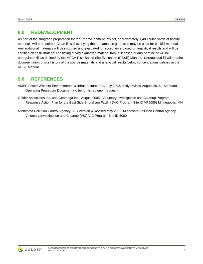
8.0 REDEVELOPMENT ........................................................................................................................................ 6
9.0 REFERENCES ................................................................................................................................................ 6
TABLES Table 1: Anticipated Material Types and Disposition
Table 2: Waste Characterization Testing Frequency for Excavated Materials
FIGURES
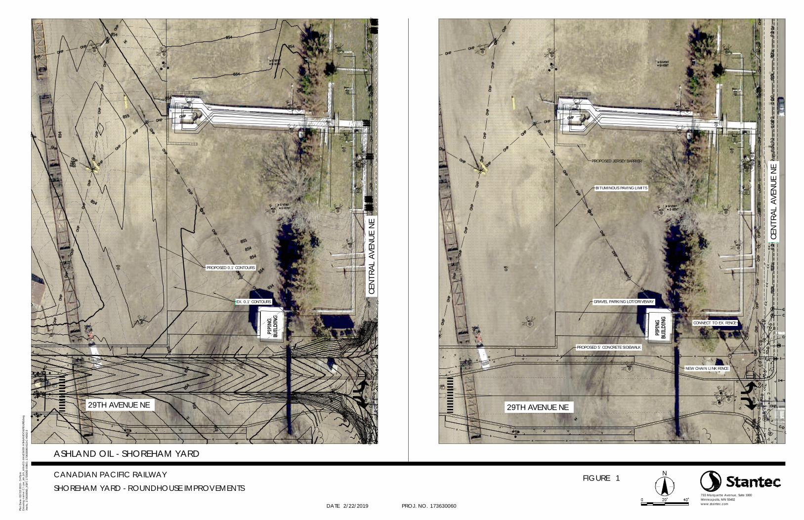
Figure 1: Site Layout
APPENDICES
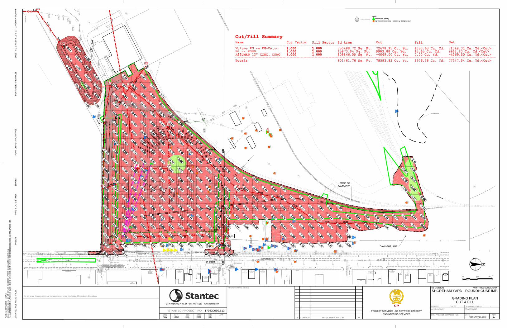
APPENDIX A Conceptual Grading Plan Cut & Fill Drawing

March 2019 023-6105
G:\PROJECTS\2002 PROJECTS\023-6105 CPR\REDEVELOPMENT PROJECT\MMCP\SENT TO MPCA\MMCP RPT.3.12.2019.DOCX 1
1.0 PURPOSE OF THE MMCP
Execution of the Redevelopment Project on the East Side of the Soo Line Shoreham Facility in Minneapolis,
Minnesota (Facility) requires the management of materials from several sources and locations in preparation for
planned redevelopment. Demolition of existing structures will produce construction debris that must be managed.
Soil excavation will be required to establish an engineered subgrade for a paved storage area and for a
stormwater retention pond. This Materials Management Contingency Plan (MMCP) provides guidance regarding
handling of materials that will be generated during demolition and subgrade preparation for the project, including
how the materials will be screened and segregated for hauling off-site for disposal or retention on-site for further
characterization and/or reuse. This MMCP identifies the data required (i.e., analytical sampling) to determine if
materials can be beneficially reused on site or require off-site disposal. The MMCP also addresses requirements
for stockpiling fill to be reused and the importation of clean backfill materials, including the approval process for
receiving such materials for use in the redevelopment.
2.0 BACKGROUND AND HISTORIC DATA
The Shoreham Facility encompasses an area of approximately 230 acres in the northern portion of Minneapolis
and has been used by Soo Line and its predecessors for railroad operations from the late 1880s through to the
present day. In addition, portions of the Facility have been leased by, or owned by, other commercial operators
since the early 1900s. The Redevelopment Project is located within the East Side Shoreham Facility in an area
known to have been contaminated by various commercial activities over time.
The East Side Shoreham Facility includes approximately 38 acres (see Figure 1) that has been used since the
1880s primarily as a rail yard by Soo Line Railroad and its predecessors. Multiple site investigations have shown
soil and groundwater impacts from petroleum related compounds and solvents and the East Side Shoreham
Facility is being remediated under the Minnesota Pollution Control Agency (MPCA) Voluntary Investigation and
Cleanup (VIC) program (Site 5080).
Response Action activities have been conducted from 2006 to date in accordance with the Response Action Plan
(RAP) for the Site dated August 31, 2005 (Golder and Geomega, 2005) approved by the MPCA on January 20,
2006. These activities have included the removal of approximately four feet of petroleum and Volatile Organic
Compound (VOC)-impacted soil in several areas, with an orange colored geotextile being placed at the bottom of
each excavation area to enable visual demarcation between placed clean fill and undisturbed soil. These
excavations were intended to address readily accessible soils and did not necessarily remove the full depth of
contaminated soil.
3.0 SURROUNDING AREA CONSIDERATIONS
The extent of the Redevelopment Project is shown in Figure 1 and is generally bounded to the east by Central
Avenue, and to the south by Saint Anthony’s Cemetery. A small tract of land along Central Avenue, identified as
the Former Ashland Lease Area (FALA), is not included within the Redevelopment Project area. Ashland Inc. (a
former tenant) retains responsibility for implementing the RAP in the FALA. Aside from providing an upgrade to
the power service, all construction activity will avoid this area so as not to impede the remediation activities of
Ashland or their subcontractors. There will be no soil disturbance in the FALA.

March 2019 023-6105
G:\PROJECTS\2002 PROJECTS\023-6105 CPR\REDEVELOPMENT PROJECT\MMCP\SENT TO MPCA\MMCP RPT.3.12.2019.DOCX 2
4.0 ANTICIPATED MATERIAL TYPES
It is anticipated that several types of materials will be encountered during demolition and excavation to the
designed subgrade elevation throughout the project area, including, but not limited to, the following:
Asphalt pavement and curbing;
Intact concrete;
Clean fill overlying demarcation geotextile within previously excavated areas;
Historic fill and contaminated soil
Miscellaneous debris from demolition of structures including, but not limited to, concrete, brick, rock, glass,
metal, plastic, wood, blocks, bars, pipe, and other building materials
Several regulated materials surveys have been completed on various structures to identify the nature and quantity
of asbestos containing materials (ACM), lead-based paint and any other regulated materials. Additional
regulated materials surveys may be performed, as necessary.
Table 1 provides the anticipated means of disposal for the identified material types.
Table 1: Anticipated Material Types and Disposition
Material Type Disposition Candidate for Direct Loading
Required Sampling to Designate Final Disposition
Asphalt Off-site disposal
Yes None
Concrete Off-site disposal
No Chip samples, as required by disposal facility
Concrete (Uncontaminated – per Beneficial Reuse (MN Administrative Rules, Part 7035.2861)
Reuse as backfill on site
No Characterization and/or sampling during the regulated materials surveys
Clean Fill Reuse as fill on site
N/A None
Historic Fill and contaminated soil
Off-site disposal
Potentially Pre-characterization or Sampling by CQA Officer following stockpiling
Miscellaneous Debris Off-site disposal
No Waste Characterization Sampling by CQA Officer following stockpiling
Demolition Debris Regulated Building Materials
Off-site disposal
Yes Sampling performed during the regulated materials surveys
Demolition Debris Non-regulated materials
Off-site disposal
Yes None

March 2019 023-6105
G:\PROJECTS\2002 PROJECTS\023-6105 CPR\REDEVELOPMENT PROJECT\MMCP\SENT TO MPCA\MMCP RPT.3.12.2019.DOCX 3
5.0 SAMPLING OF EXCAVATED MATERIALS
Waste characterization sampling of excavated materials will be performed to meet the sampling frequency
required by the disposal facility identified by the client. As a reference, Table 2 presents the frequency of testing
by Vonco Landfill in accordance with MPCA Rules, Chapter 7045. Per the Conceptual Grading Plan Cut & Fill
drawing prepared by Stantec dated February 26, 2018 (Appendix A), it is anticipated that approximately 79,000
cubic yards (cy) of excavated material will be generated during subgrade preparation for the Redevelopment
Project and the establishment of a retention pond, including approximately 6,700 cy of previously placed imported
clean fill (volume obtained from Sunde Land Surveying, LLC dated November 3, 2006).
Previously placed clean fill will be segregated and stockpiled for reuse. The remaining excavated materials may
either be direct loaded for off-site disposal based on pre-excavation sampling and field screening or may be
stockpiled and sampled post-excavation. Sampling frequency requirements are provided in Table 2. Waste
characterization samples will be analyzed for VOCs, Gasoline Range Organics (GRO), Diesel Range Organics
(DRO), Polychlorinated biphenyls (PCBs), Toxicity characteristic leaching procedure (TCLP) metals (or total
metals and evaluation by 20 times rule), flashpoint, paint filter test, and any other tests as required by the disposal
facility.
Table 2: Waste Characterization Testing Frequency for Excavated Materials
5.1 Soil Management with Pre-excavation Sampling
In order to reduce the volume of materials to be stockpiled, pre-excavation sampling may be undertaken, to
determine if direct loading of the excavated materials will be acceptable to the selected disposal facility. Pre-
excavation samples will be biased to the depths of greatest impact as indicated by field screening including visual
and olfactory means, and a photo-ionization detector (PID) or flame ionization detector (FID). The pre-
characterization samples will be collected at approximately the midpoint depth of proposed excavations.
Sampling will be conducted using test pits or shallow direct-push drilling methods. Sampling will follow the
procedures outlined in the Standard Operating Procedure Document (SOP) for the Facility (AMEC, 2015) as
applicable. Quality assurance procedures will be in accordance with the SOP including verification that
laboratories and testing equipment comply with standards, checking test equipment calibration data against
certified standards, and chain of custody procedures for analytical samples.
Upon completion of pre-excavation sampling, the proposed excavation area will be divided into sectors of similar
soils to assist in the management of the excavated soils. Sectors will be marked with paint or other suitable
identifiers. During the excavation of soils, an environmental technician will be onsite to perform additional
inspection of the excavated soils to determine their potential classification as clean soils for reuse onsite,
potentially contaminated soils for further assessment, or contaminated soils for transport and disposal off-site.
March 2019 023-6105
G:\PROJECTS\2002 PROJECTS\023-6105 CPR\REDEVELOPMENT PROJECT\MMCP\SENT TO MPCA\MMCP RPT.3.12.2019.DOCX 4
Inspection will include visual and olfactory assessment and field screening using an appropriately calibrated PID
or FID. Each instrument will be calibrated before the start of screening each day. The environmental technician
will be stationed upwind of all excavations being performed and will have the analytical data from any pre-
characterization sampling available. Soils will be field-screened as they are removed and prior to loading in the
haul truck. The frequency of screening will be based on visual/olfactory evidence and PID readings but shall
include at least one representative sample for every 10 cubic yards of excavated soils. The screening methods
and readings will be documented in the field as they are obtained. Soils not meeting disposal facility requirements
for direct loading will be stockpiled for additional testing.
5.2 Soil Management without Pre-excavation Sampling
Overall, the Redevelopment Project will consist of two main areas of excavation within the construction footprint.
Excavation activities in the southern portion for the proposed retention basin will cover an area of approximately
46,000 square feet (sf) with the excavation extending up to approximate depth of 11.5 feet. The remaining portion
of the construction footprint designated for the paved storage area will cover approximately 756,000 sf and have
an average depth of approximately 2.5 feet. The excavated soils from both areas will equate to the total
estimated 79,000 cy of soils to be excavated in the Redevelopment Project.
Clean fill soil overlying the demarcation geotextile within the previously excavated areas that does not contain
trash or debris, or show signs of staining, odor or PID detections will be stockpiled separately with the intent for
reuse as fill material within the limits of the construction site. Approximately 6,700 cy of clean soils are
anticipated.
Other excavated soils from outside the known clean fill area will be field screened using the methods described in
section 5.1 and will be stockpiled on site as follows:
Soils that show no evidence of trash or debris, or visual staining, but have a PID reading of <10ppm, will be
placed in a “Potentially Contaminated Soils” stockpile for further characterization testing prior to disposal.
Approximately 65,000 to 70,500 cy of Potentially Contaminated Soil is anticipated. This volume of Potentially
Contaminated Soil will be segregated into smaller stockpiles based on similar characteristics (e.g., color, texture,
etc).
Soils containing trash and debris, visual staining or PID readings >10ppm will be placed in a separate
“Contaminated Soils” stockpile for further characterization testing prior to disposal. Approximately 1,000 to 2,000
cy of contaminated soil is anticipated.
Excavation activities shall be observed by the environmental technician and any unexpected conditions, such as
the presence of free product or potentially hazardous materials will result in such materials being diverted to a
separate on-site stockpile for further characterization.
Construction debris not containing regulated materials may be direct loaded for off-site disposal or staged in a
separate stockpile area prior to disposal. Regulated materials shall be handled separately and in accordance with
all applicable requirements.
March 2019 023-6105
G:\PROJECTS\2002 PROJECTS\023-6105 CPR\REDEVELOPMENT PROJECT\MMCP\SENT TO MPCA\MMCP RPT.3.12.2019.DOCX 5
6.0 IMPLEMENTATION
Prior to excavation activities in the southeasterly corner of the Redevelopment Project, a new building to
accommodate the existing pump and treat (P&T) equipment will be constructed outside the limits of the proposed
paved storage area. The existing equipment will be relocated to the new building with appropriate piping
modifications to maintain discharge requirements. The P&T system and the associated wells shall be protected to
prevent damage or comprise to the operation of the remediation system. If any P&T components or wells are
damaged during construction or relocation, they shall be repaired in a timely manner.
During excavation of soils and other materials, it is anticipated that temporary stockpiles will be constructed in an
area north of the FALA (see Figure 1).
If pre-excavation sampling of soils is undertaken, sample identification numbers will be assigned consistent with
procedures used at the Site during prior investigations. The sample identification will indicate the general location,
depth, and date that the sample was collected. Samples will be transported to the designated analytical laboratory
for analysis. Completion of all laboratory testing is expected to require a period of approximately three weeks.
A licensed surveyor will be utilized to locate and determine the ground surface elevation at each pre-excavation
sample to accurately establish lateral and vertical locations of samples.
Upon completion of the pre-excavation sampling (if undertaken), figures will be developed using the analytical
data to delineate the limits of excavation which meet the requirements for direct hauling to off-site disposal as
approved by the disposal facility. If additional sampling or analyses are required for an excavation area, that area
will be identified as material to be stockpiled and protected on site pending analysis and will not be direct loaded
for disposal.
7.0 MATERIALS MANANGEMENT DURING CONSTRUCTION
All temporary stockpiles will be covered with polyethylene sheeting and sand bags when not in use. All stockpiles
will be covered before rain events and at the end of every work day to minimize the generation of contact water
and for dust control.
All stockpile areas will be constructed to be stable against collapse, prevent surface water run-on or runoff, and
meet the construction details outlined in an approved Erosion and Sediment Control Plan. Stockpile areas will
have perimeter and surface erosion control measures.
Excavated soil designated for reuse as backfill will be stockpiled in a suitable location to minimize handling and
facilitate efficient backfilling operations. A similar procedure will be used when determining stockpile locations for
imported soil material brought on-site for use as backfill. Imported soil will be segregated from impacted soils at
all times.
Impacted material designated for off-site disposal will be sent to disposal facilities that have been pre-selected by
Canadian Pacific to receive the designated materials and subject to pre-approval by the disposal facility.
Waste transporters will post appropriate placards on transport vehicles according to the requirements outlined in
applicable Department of Transportation (DOT) regulations. Waste shipment documentation, including Waste
Profiles and manifests or Bills of Lading, as applicable, will be prepared and provided to Canadian Pacific for
review and execution prior to transport.
March 2019 023-6105
G:\PROJECTS\2002 PROJECTS\023-6105 CPR\REDEVELOPMENT PROJECT\MMCP\SENT TO MPCA\MMCP RPT.3.12.2019.DOCX 6
8.0 REDEVELOPMENT
As part of the subgrade preparation for the Redevelopment Project, approximately 1,400 cubic yards of backfill
materials will be required. Clean fill soil overlying the demarcation geotextile may be used for backfill material.
Any additional materials will be imported and evaluated for acceptance based on analytical results and will be
certified clean fill material consisting of virgin quarried material from a licensed quarry or mine or will be
unregulated fill as defined by the MPCA Risk-Based Site Evaluation (RBSE) Manual. Unregulated fill will require
documentation of site history of the source materials and analytical results below concentrations defined in the
RBSE Manual.
9.0 REFERENCES
AMEC Foster Wheeler Environmental & Infrastructure, Inc., July 2002, lastly revised August 2015. Standard
Operating Procedure Document (to be furnished upon request)
Golder Associates Inc. and Geomega Inc., August 2005. Voluntary Investigation and Cleanup Program
Response Action Plan for the East Side Shoreham Facility (VIC Program Site ID VP5080) Minneapolis, MN
Minnesota Pollution Control Agency, VIC Version 4 Revised May 2002. Minnesota Pollution Control Agency,
Voluntary Investigation and Cleanup (VIC) VIC Program Site ID 5080

© 2019 Microsoft Corporation © 2019 DigitalGlobe ©CNES (2019) Distribution Airbus DS
ROUND HOUSE TO BE DEMOLISHED
STOCKPILES
0
FEET
120 240
1'' = 120'
LEGEND
REFERENCE(S)
NJ Authorization #24GA28029100
01
in
023-6105CONTROLDD001
FIGURE
10
2019-03-11
AM
MW
CBM
PSF
MATERIAL MANAGEMENT CONTINGENCY PLAN
SOO LINE SHOREHAM FACILITYMINNEAPOLIS, MINNESOTA
SITE LAYOUT TITLE
PROJECT NO. REV.
PROJECT
CLIENT
IF T
HIS
MEA
SUR
EMEN
T D
OES
NO
T M
ATC
H W
HAT
IS S
HO
WN
, TH
E SH
EET
SIZE
HAS
BEE
N M
OD
IFIE
D F
RO
M: A
NSI
D
CONSULTANT
PREPARED
DESIGNED
REVIEWED
APPROVED
YYYY-MM-DD
Path
: \\m
tlaur
el\c
add\
Proj
ects
\200
2\02
3-61
05
Soo
Line
Sho
reha
m Y
ard\
PRO
DU
CTI
ON
\DD
- R
ound
Hou
se D
emo
- Soi
l Con
tinge
ncy
Man
agem
ent P
lan\
| F
ile N
ame:
023
6105
DD
001.
dwg
| L
ast E
dite
d By
: am
oral
es D
ate:
201
9-03
-07
Tim
e:2:
04:2
2 PM
| P
rinte
d By
: AM
oral
es
Dat
e: 2
019-
03-1
1 T
ime:
3:20
:32
PM
PREVIOUSLY EXCAVATED AND BACKFILLED WITH CLEAN FILL(SEE REFERENCE 3)
1. AERIAL COURTESY © 2018 MICROSOFT CORPORATION © 2018 DIGITALGLOBE © CNES(2018) DISTRIBUTION AIRBUS DS BING.
2. LOCATION OF WELLS PROVIDED BY AMEC EARTH AND ENVIRONMENTAL, INC.3. EXCAVATION AREAS SURVEYED AND PROVIDED BY SUNDE LAND SURVEYING, LLC, DATED
NOVEMBER 3, 2006 (EXCAVATION PITS.DWG).4. EXCAVATION FOR ROUND HOUSE REDEVELOPMENT DIGITIZED FROM FIGURE TITLED
"SHOREHAM YARD - ROUNDHOUSE IMP. GRADING PLAN CUT & FILL," PREPARED BYSTANTEC, DATED FEBRUARY 26, 2019 (1730060-GRADINGEXHIBIT-CUT_FILL FIG 1.PDF).
MONITORING WELL (SEE REFERENCE 2)
EXCAVATION FOR ROUND HOUSE REDEVELOPMENT (SEE REFERENCE 4)
PROPOSED STORMWATERRETENTION POND
PROPOSED STORMWATERRETENTION POND
PROPOSED STORMWATERRETENTION POND
PROPOSED STORMWATERRETENTION POND
PROPOSED STORMWATERRETENTION POND
PROPOSED STORMWATERRETENTION POND
PROPOSED STORMWATERRETENTION POND
PROPOSED STORMWATERRETENTION POND
PROPOSED STORMWATERRETENTION POND
PROPOSED STORMWATERRETENTION POND
PROPOSED STORMWATERRETENTION POND
PROPOSED STORMWATERRETENTION POND
PROPOSED STORMWATERRETENTION POND
PROPOSED STORMWATERRETENTION POND
PROPOSED STORMWATERRETENTION POND
PROPOSED STORMWATERRETENTION POND
PROPOSED STORMWATERRETENTION POND
SHOREHAM FACILITYSHOREHAM FACILITYSHOREHAM FACILITYSHOREHAM FACILITYSHOREHAM FACILITYSHOREHAM FACILITYSHOREHAM FACILITYSHOREHAM FACILITYSHOREHAM FACILITYSHOREHAM FACILITYSHOREHAM FACILITYSHOREHAM FACILITYSHOREHAM FACILITYSHOREHAM FACILITYSHOREHAM FACILITYSHOREHAM FACILITYSHOREHAM FACILITY
CEN
TRAL
AVE
NU
EC
ENTR
AL A
VEN
UE
CEN
TRAL
AVE
NU
EC
ENTR
AL A
VEN
UE
CEN
TRAL
AVE
NU
EC
ENTR
AL A
VEN
UE
CEN
TRAL
AVE
NU
EC
ENTR
AL A
VEN
UE
CEN
TRAL
AVE
NU
EC
ENTR
AL A
VEN
UE
CEN
TRAL
AVE
NU
EC
ENTR
AL A
VEN
UE
CEN
TRAL
AVE
NU
EC
ENTR
AL A
VEN
UE
CEN
TRAL
AVE
NU
EC
ENTR
AL A
VEN
UE
CEN
TRAL
AVE
NU
E
SAINT ANTHONY'S CEMETERYSAINT ANTHONY'S CEMETERYSAINT ANTHONY'S CEMETERYSAINT ANTHONY'S CEMETERYSAINT ANTHONY'S CEMETERYSAINT ANTHONY'S CEMETERYSAINT ANTHONY'S CEMETERYSAINT ANTHONY'S CEMETERYSAINT ANTHONY'S CEMETERYSAINT ANTHONY'S CEMETERYSAINT ANTHONY'S CEMETERYSAINT ANTHONY'S CEMETERYSAINT ANTHONY'S CEMETERYSAINT ANTHONY'S CEMETERYSAINT ANTHONY'S CEMETERYSAINT ANTHONY'S CEMETERYSAINT ANTHONY'S CEMETERY
FORMER ASHLAND LEASE AREA
FORMER ASHLAND LEASE AREA

APPENDIX A
Conceptual Grading Plan Cut & Fill
Drawing
Plot
Da
te:0
2/21
/201
9-1
2:17
pmD
raw
ing
nam
e:C
:\pw
_stn
_bh_
infra
01\d
ms2
3400
\173
0060
-Gra
ding
Exhi
bit-C
ut_F
ill.dw
gXr
efs:,
1730
060-
XSN
O,1
7363
0060
-613
-C-H
D02
-3,1
7363
0060
_XSX
T,17
3006
0-XS
ST,1
7300
60-X
SSS,
3006
0_61
3_TT
LB,1
7300
60-X
SPL
N
PROFESSIONAL SEALS
YY/MM/DD BY
Do not scale this document. All measurements must be obtained from stated dimensions.
DRN CHK DES IDRENG APP ENGINEERING SERVICES DIR. PROJECT SERVICES - US:R REVISION DESCRIPTION
REVRPRESLPJW
US DIVISION
173630060.613
A
SHOREHAM YARD - ROUNDHOUSE IMP.
STANTEC PROJECT NO:
NRW
SHEE
TSI
ZE:A
NSI
B11
"x17
"(27
9.9m
mx
431.
8mm
)$F
ILE$
STAN
TEC
FILE
NAM
E:TI
ME
&D
ATE:
$PLT
DRV
S$PL
OT
DR
IVER
:$P
ENTB
LS$
PEN
TABL
E:$T
IME$
$DAT
E$$U
SER$
DWG BY: CHK BY:APPROVED BY: DRAWING NO:
PROJECT SERVICES - US NETWORK CAPACITY
WHITROW SUBDIVISION
2335 Highway 36 W, St. Paul, MN 55113 www.stantec.com
GS
DRAWING STATUS: -
DATE:FEBRUARY 26, 2019
GRADING PLAN
DAYLIGHT LINE
CUT & FILL
EDGE OFPAVEMENT
DATE PROJ. NO.
Plot
Da
te:0
2/22
/201
9-3
:47p
mD
raw
ing
nam
e:C
:\pw
_stn
_bh_
infra
01\d
ms2
3400
\ASH
LAN
DO
ILFIG
URE.
dwg
Xref
s:,17
3630
060_
XSXT
,173
0060
-XSN
O,1
7363
0060
-613
-C-H
D02
-3
733 Marquette Avenue, Suite 1000Minneapolis, MN 55402www.stantec.com
ASHLAND OIL - SHOREHAM YARD
CANADIAN PACIFIC RAILWAY
SHOREHAM YARD - ROUNDHOUSE IMPROVEMENTS
2/22/2019 173630060
FIGURE 1
GRAVEL PARKING LOT/DRIVEWAY
PROPOSED JERSEY BARRIER
BITUMINOUS PAVING LIMITS
29TH AVENUE NE29TH AVENUE NE
CEN
TRAL
AVEN
UE
NE
CEN
TRAL
AVEN
UE
NE
N
PROPOSED 5' CONCRETE SIDEWALK
CONNECT TO EX. FENCE
NEW CHAIN LINK FENCE
EX. 0.1' CONTOURS
PROPOSED 0.1' CONTOURS

golder.com


![Winter Contingency Plan 2019 - PDMA Contingency... · 2020. 12. 24. · [KHYBER PAKHTUNKHWA WINTER CONTINGENCY PLAN 2019-20] Winter Contingency Plan 5 | Page utilizing PAF strategic](https://img.pdfslide.net/doc/110x75/611400065caf3c03a80f7591/winter-contingency-plan-2019-pdma-contingency-2020-12-24-khyber-pakhtunkhwa.jpg)


![Template for BUSINESS CONTINGENCY · PDF fileTemplate for BUSINESS CONTINGENCY PLAN EFFECTIVE DATE: [effective_date] DISCLAIMER The materials presented herein are for general reference](https://img.pdfslide.net/doc/110x75/5a794ad17f8b9ae93a8cc0ec/template-for-business-contingency-for-business-contingency-plan-effective-date.jpg)