Embed Size (px)
Citation preview

This report must not be used to claim product certification, approval, or endorsement by NVLAP, NIST, or any agency of the federal government of the United States of America. This Report shall not be reproduced, except in full without written approval of the laboratory.
Sensoteq Ltd
Vibration Monitoring System
FCC 15.231:2017
Periodic Transmitter
Report # ELEM0040.1
NVLAP Lab Code: 200676-0
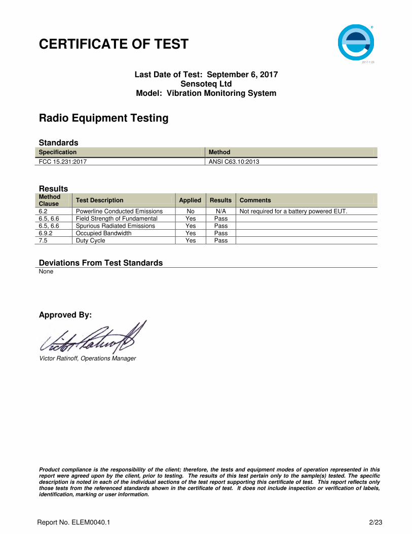
CERTIFICATE OF TEST
2017-1-25
Product compliance is the responsibility of the client; therefore, the tests and equipment modes of operation represented in this report were agreed upon by the client, prior to testing. The results of this test pertain only to the sample(s) tested. The specific description is noted in each of the individual sections of the test report supporting this certificate of test. This report reflects only those tests from the referenced standards shown in the certificate of test. It does not include inspection or verification of labels, identification, marking or user information.
Last Date of Test: September 6, 2017 Sensoteq Ltd
Model: Vibration Monitoring System
Radio Equipment Testing
Standards Specification Method
FCC 15.231:2017 ANSI C63.10:2013
Results Method Clause
Test Description Applied Results Comments
6.2 Powerline Conducted Emissions No N/A Not required for a battery powered EUT.
6.5, 6.6 Field Strength of Fundamental Yes Pass
6.5, 6.6 Spurious Radiated Emissions Yes Pass
6.9.2 Occupied Bandwidth Yes Pass
7.5 Duty Cycle Yes Pass
Deviations From Test Standards None
Approved By:
Victor Ratinoff, Operations Manager
Report No. ELEM0040.1 2/23

REVISION HISTORY
2017.1.25
Revision Number
Description Date Page Number
00 None
Report No. ELEM0040.1 3/23
ACCREDITATIONS AND AUTHORIZATIONS
2017.6.12
United States
FCC - Designated by the FCC as a Telecommunications Certification Body (TCB). Certification chambers, Open Area Test Sites, and conducted measurement facilities are listed with the FCC.
A2LA - Accredited by A2LA to ISO / IEC 17065 as a product certifier. This allows Element to certify transmitters to FCC and IC
specifications.
NVLAP - Each laboratory is accredited by NVLAP to ISO 17025
Canada
ISED - Recognized by Innovation, Science and Economic Development Canada as a Certification Body (CB). Certification chambers
and Open Area Test Sites are filed with ISED.
European Union
European Commission – Within Element, we have a EU Notified Body validated for the EMCD and RED Directives.
Australia/New Zealand
ACMA - Recognized by ACMA as a CAB for the acceptance of test data.
Korea
MSIP / RRA - Recognized by KCC’s RRA as a CAB for the acceptance of test data.
Japan
VCCI - Associate Member of the VCCI. Conducted and radiated measurement facilities are registered.
Taiwan
BSMI – Recognized by BSMI as a CAB for the acceptance of test data.
NCC - Recognized by NCC as a CAB for the acceptance of test data.
Singapore
IDA – Recognized by IDA as a CAB for the acceptance of test data.
Israel
MOC – Recognized by MOC as a CAB for the acceptance of test data.
Hong Kong
OFCA – Recognized by OFCA as a CAB for the acceptance of test data.
Vietnam
MIC – Recognized by MIC as a CAB for the acceptance of test data.
SCOPE For details on the Scopes of our Accreditations, please visit:
http://portlandcustomer.element.com/ts/scope/scope.htm
http://gsi.nist.gov/global/docs/cabs/designations.html
Report No. ELEM0040.1 4/23

MEASUREMENT UNCERTAINTY
TMU.2015.07.10
Measurement Uncertainty When a measurement is made, the result will be different from the true or theoretically correct value. The difference is the result of tolerances in the measurement system that cannot be completely eliminated. To the extent that technology allows us, it has been our aim to minimize this error. Measurement uncertainty is a statistical expression of measurement error qualified by a probability distribution. A measurement uncertainty estimation has been performed for each test per our internal quality document QM205.4.6. The estimation is used to compare the measured result with its "true" or theoretically correct value. The expanded measurement uncertainty (K=2) can be found included as part of the applicable test description page. Our measurement data meets or exceeds the measurement uncertainty requirements of the applicable specification; therefore, the test data can be compared directly to the specification limit to determine compliance. The calculations for estimating measurement uncertainty are based upon ETSI TR 100 028 (or CISPR 16-4-2 as applicable), and are available upon request. The following table represents the Measurement Uncertainty (MU) budgets for each of the tests that may be
contained in this report.
Test + MU - MU
Frequency Accuracy (Hz) 0.0007% -0.0007%
Amplitude Accuracy (dB) 1.2 dB -1.2 dB
Conducted Power (dB) 0.3 dB -0.3 dB
Radiated Power via Substitution (dB) 0.7 dB -0.7 dB
Temperature (degrees C) 0.7°C -0.7°C
Humidity (% RH) 2.5% RH -2.5% RH
Voltage (AC) 1.0% -1.0%
Voltage (DC) 0.7% -0.7%
Field Strength (dB) 5.2 dB -5.2 dB
AC Powerline Conducted Emissions (dB) 2.4 dB -2.4 dB
Report No. ELEM0040.1 5/23

FACILITIES
2017.7.25
California Labs OC01-13
41 Tesla Irvine, CA 92618 (949) 861-8918
Minnesota Labs MN01-08, MN10
9349 W Broadway Ave. Brooklyn Park, MN 55445
(612)-638-5136
New York Labs NY01-04
4939 Jordan Rd. Elbridge, NY 13060
(315) 554-8214
Oregon Labs EV01-12
22975 NW Evergreen Pkwy Hillsboro, OR 97124
(503) 844-4066
Texas Labs TX01-09
3801 E Plano Pkwy Plano, TX 75074 (469) 304-5255
Washington Labs NC01-05
19201 120th Ave NE Bothell, WA 98011
(425)984-6600
NVLAP
NVLAP Lab Code: 200676-0 NVLAP Lab Code: 200881-0 NVLAP Lab Code: 200761-0 NVLAP Lab Code: 200630-0 NVLAP Lab Code:201049-0 NVLAP Lab Code: 200629-0
Innovation, Science and Economic Development Canada
2834B-1, 2834B-3 2834E-1, 2834E-3 N/A 2834D-1, 2834D-2 2834G-1 2834F-1
BSMI
SL2-IN-E-1154R SL2-IN-E-1152R N/A SL2-IN-E-1017 SL2-IN-E-1158R SL2-IN-E-1153R
VCCI
A-0029 A-0109 N/A A-0108 A-0201 A-0110
Recognized Phase I CAB for ACMA, BSMI, IDA, KCC/RRA, MIC, MOC, NCC, OFCA
US0158 US0175 N/A US0017 US0191 US0157
Report No. ELEM0040.1 6/23

Test Setup Block Diagrams
2017.1.25
Antenna Port Conducted Measurements
Near Field Test Fixture Measurements
Spurious Radiated Emissions
EUT DC Block and
Attenuator Spectrum Analyzer
RF Adapter Coaxial Cable
3m Test Distance
Spectrum Analyzer
Measurement Antenna
Coaxial Cable
EUT
Flush Mounted Turn table, Non-reflective foam table to
support EUT
Fully anechoic shielded enclosure above 1 GHz.
Semi-anechoic below 1 GHz (No absorber on the floor).
Preamp and
Filters
EUT
Spectrum Analyzer
Coaxial Cable
Near Field
Probe
Report No. ELEM0040.1 7/23

PRODUCT DESCRIPTION
2017-1-25
Client and Equipment Under Test (EUT) Information Company Name: Sensoteq Ltd Address: Unit 18 Ormeau Business Park City, State, Zip: 8 Cromac Avenue, Belfast BT7 2JZ Northern Ireland Test Requested By: Alex Toohie of Element Materials Technology Warwick Ltd. Model: Vibration Monitoring System First Date of Test: September 6, 2017 Last Date of Test: September 6, 2017 Receipt Date of Samples: September 6, 2017 Equipment Design Stage: Production Equipment Condition: No Damage Purchase Authorization: Verified
Information Provided by the Party Requesting the Test Functional Description of the EUT:
Vibration Monitoring System containing a low power transmitter which operates at 433 MHz utilizing GFSK modulation.
Testing Objective:
To demonstrate compliance of the periodic radio to FCC 15.231(e) requirements.
Report No. ELEM0040.1 8/23

CONFIGURATIONS
2017-1-25
Configuration ELEM0040- 1 EUT
Description Manufacturer Model/Part Number Serial Number
Vibration Monitoring System (10 sec) Sensoteq Ltd ANTS1001 16BE04
Configuration ELEM0040- 2 EUT
Description Manufacturer Model/Part Number Serial Number
Vibration Monitoring System (100%) Sensoteq Ltd ANTS1001 16BE03
Report No. ELEM0040.1 9/23

MODIFICATIONS
2017-1-25
Equipment Modifications
Item Date Test Modification Note Disposition of EUT
1 9/6/2017 Field Strength of Fundamental
Tested as delivered to Test Station.
No EMI suppression devices were added or modified during this test.
EUT remained at Element following the test.
2 9/6/2017 Spurious Radiated Emissions
Tested as delivered to Test Station.
No EMI suppression devices were added or modified during this test.
EUT remained at Element following the test.
3 9/6/2017 Occupied Bandwidth
Tested as delivered to Test Station.
No EMI suppression devices were added or modified during this test.
EUT remained at Element following the test.
4 9/6/2017 Duty Cycle Tested as delivered to Test Station.
No EMI suppression devices were added or modified during this test.
Scheduled testing was completed.
Report No. ELEM0040.1 10/23

FIELD STRENGTH OF FUNDAMENTAL
PSA-ESCI 2017.06.01
description PSA-ESCI 2017.06.01
MODES OF OPERATION
Continuously Transmitting at 433 MHz
POWER SETTINGS INVESTIGATED
Battery
CONFIGURATIONS INVESTIGATED
ELEM0040 - 2
FREQUENCY RANGE INVESTIGATED
Start Frequency 432 MHz Stop Frequency 434 MHz
SAMPLE CALCULATIONS
Radiated Emissions: Field Strength = Measured Level + Antenna Factor + Cable Factor - Amplifier Gain + Distance Adjustment Factor + External Attenuation
TEST EQUIPMENT
ID Interval
OCH 12 mo
AXB 24 mo
AFJ 12 mo
TEST DESCRIPTION
Testing was performed using the mode(s) of operation and configuration(s) noted within the report. The individuals and/or the
organization requesting the test provided the modes, configurations and settings used to complete the evaluation. The actual test
parameters are specified in the test data, this includes items such as investigated frequency range (scanned) and test levels. The
testing methods and performance specifications, as well as the test site used for the evaluation are indicated in the test data. The
test data represents the configuration / operating mode/ model that produced the highest emission levels as compared to the
specification limit.
Description Last Cal.ModelManufacturer
Analyzer - Spectrum Analyzer Agilent N9010A 1/28/2017
Antenna - Biconilog EMCO 3142 11/6/2015
Cable Element 10kHz-1GHz RE Cables 8/1/2017
The antennas to be used with the EUT were tested. The EUT was configured for continuous modulated operation at its single transmit frequency. The field strength of the transmit frequency was maximized by rotating the EUT, adjusting the measurement antenna height and polarization, and manipulating the EUT in 2 orthogonal planes (per ANSI C63.10:2013).
To derive average emission measurements, a duty cycle correction factor was utilized:
Duty Cycle = On time/100 milliseconds (or the period, whichever is less)
Where “On time” = N1L1 +N2L2 +….
Where N1 is the number of type 1 pulses, L1 is length of type 1 pulses, N2 is the number of type 2 pulses, L2 is the length of type 2 pulses, etc.
Therefore, Duty Cycle = (N1L1 +N2L2 +…)/100mS or T, whichever is less. (Where T is the period of the pulse train.)
The measured values for the EUT’s pulse train are as follows:
Period = 98.43 mSecPulsewidth of Type 1 Pulse = 17.73 mSecNumber of Type 1 Pulses = 1
Duty Cycle = 20 log [((1)(17.73))/98.43] = -14.89 dB
The duty cycle correction factor of –14.89 dB was added to the peak readings to mathematically derive the average levels. Peak measurements were made with a resolution bandwidth of 100kHz and a video bandwidth of 300kHz.
Report No. ELEM0040.1 11/23

PSA-ESCI 2017.06.01
oats EmiR5 2017.07.11 PSA-ESCI 2017.06.01
Work Order: Date:
Project: Temperature:
Job Site: Humidity: Johnny Candelas.jpg
Serial Number: Tested by: Johnny Candelas
EUT: Vibration Monitoring System
Configuration: 2
Sensoteq Ltd
Attendees: Idir Boudaoud
Battery
Test Specifications Test Method
Run # 3 Test Distance (m) 3 Antenna Height(s) ResultsEN 55022 (Amds. A1:2000 A2:2003) Class B
Freq Amplitude Factor Antenna Height Azimuth
Duty Cycle
Correction
External
Attenuation
Polarity/
Transducer
Type Detector
Distance
Adjustment Adjusted Spec. Limit
Compared to
Spec.
(MHz) (dBuV) (dB) (meters) (degrees) Factor
(dB)
(dB) (dB) (dBuV/m) (dBuV/m) (dB)
Comments
433.000 63.2 23.4 1.3 180.0 -14.9 0.0 Vert AV 0.0 71.7 72.8 -1.1 EUT Horiz
432.998 63.1 23.4 1.3 351.0 -14.9 0.0 Vert AV 0.0 71.6 72.8 -1.2 EUT Vert
432.997 62.0 23.4 1.0 271.0 -14.9 0.0 Horz AV 0.0 70.5 72.8 -2.3 EUT Horiz
432.998 61.9 23.4 2.1 37.0 -14.9 0.0 Horz AV 0.0 70.4 72.8 -2.4 EUT Vert
433.000 63.2 23.4 1.3 180.0 0.0 Vert PK 0.0 86.6 92.8 -6.2 EUT Horiz
432.998 63.1 23.4 1.3 351.0 0.0 Vert PK 0.0 86.5 92.8 -6.3 EUT Vert
432.997 62.0 23.4 1.0 271.0 0.0 Horz PK 0.0 85.4 92.8 -7.4 EUT Vert
432.998 61.9 23.4 2.1 37.0 0.0 Horz PK 0.0 85.3 92.8 -7.5 EUT Horiz
FIELD STRENGTH OF FUNDAMENTAL
ELEM0040 09/06/17
None 22.9 °C
OC10 45.2% RH
16BE03 Barometric Pres.: 1017 mbar
Customer:
EUT Power:
Operating Mode:Continuously Transmitting at 433 MHz
Deviations:None
Comments:Power Setting -6, using -14.89dB DCCF
FCC 15.231:2017 ANSI C63.10:2013
1 to 4(m) Pass
0
10
20
30
40
50
60
70
80
90
100
432.0 432.2 432.4 432.6 432.8 433.0 433.2 433.4 433.6 433.8 434.0
dB
uV
/m
MHz
Report No. ELEM0040.1 12/23

SPURIOUS RADIATED EMISSIONS
PSA-ESCI 2017.06.01
description PSA-ESCI 2017.06.01
MODES OF OPERATION
Continuously Transmitting at 433 MHz
POWER SETTINGS INVESTIGATED
Battery
CONFIGURATIONS INVESTIGATED
ELEM0040 - 2
FREQUENCY RANGE INVESTIGATED
Start Frequency 30 MHz Stop Frequency 5000 MHz
SAMPLE CALCULATIONS
Radiated Emissions: Field Strength = Measured Level + Antenna Factor + Cable Factor - Amplifier Gain + Distance Adjustment Factor + External Attenuation
TEST EQUIPMENT
ID Interval
AOP 12 mo
OCJ 12 mo
AHB 24 mo
TKP 0 moAOZ 12 mo
OCH 12 mo
AXB 24 moAFJ 12 mo
Amplifier - Pre-Amplifier Miteq AMF-4D-010120-30-10P-1 7/13/2017
Antenna - Double Ridge EMCO 3115 3/21/2016
Cable Element 1-8GHz RE Cables 7/13/2017
Miteq AM-1402 8/1/2017
Attenuator Fairview Microwave SA18H-10 NCR
Antenna - Biconilog EMCO 3142 11/6/2015
Cable Element 10kHz-1GHz RE Cables 8/1/2017
Manufacturer
Analyzer - Spectrum Analyzer Agilent N9010A
Amplifier - Pre-Amplifier
Testing was performed using the mode(s) of operation and configuration(s) noted within the report. The individuals and/or the
organization requesting the test provided the modes, configurations and settings used to complete the evaluation. The actual test
parameters are specified in the test data, this includes items such as investigated frequency range (scanned) and test levels. The
testing methods and performance specifications, as well as the test site used for the evaluation are indicated in the test data. The
test data represents the configuration / operating mode/ model that produced the highest emission levels as compared to the
specification limit.
Description Last Cal.Model
1/28/2017
Report No. ELEM0040.1 13/23

TEST DESCRIPTION
The highest gain antenna of each type to be used with the EUT was tested. The EUT was configured for the required transmit frequency in each operational band and the modes as showed in the data sheets.
For each configuration, the spectrum was scanned throughout the specified range as part of the exploratory investigation of the emissions. These “pre-scans” are not included in the report. Final measurements on individual emissions were then made and included in this test report.
The individual emissions from the EUT were maximized by rotating the EUT on a turntable, adjusting the position of the EUT and EUT antenna in three orthogonal axis, and adjusting the measurement antenna height and polarization (per ANSI C63.10). A preamp and high pass filter (and notch filter) were used for this test in order to provide sufficient measurement sensitivity.
Measurements were made with the required detectors and annotated on the data for each individual point using the following annotation:
QP = Quasi-Peak DetectorPK = Peak DetectorAV = RMS Detector
To derive average emission measurements, a duty cycle correction factor was utilized:
Duty Cycle = On time/100 milliseconds (or the period, whichever is less)
Where “On time” = N1L1 +N2L2 +….
Where N1 is the number of type 1 pulses, L1 is length of type 1 pulses, N2 is the number of type 2 pulses, L2 is the length of type 2 pulses, etc.
Therefore, Duty Cycle = (N1L1 +N2L2 +…)/100mS or T, whichever is less. Where T is the period of the pulse train.
The measured values for the EUT’s pulse train are as follows:
Period = 98.43 mSecPulsewidth of Type 1 Pulse = 17.73 mSecNumber of Type 1 Pulses = 1
Duty Cycle = 20 log [((1)(17.73))/98.43] = -14.89 dB
The duty cycle correction factor of –14.89 dB was added to the peak readings to mathematically derive the average levels. Peak measurements were made with a resolution bandwidth of 100kHz and a video bandwidth of 300kHz for measurements at or below 1GHz. Above 1GHz, a resolution bandwidth of 1MHz and a video bandwidth of 3MHz was used.
Report No. ELEM0040.1 14/23

PSA-ESCI 2017.06.01
oats EmiR5 2017.07.11 PSA-ESCI 2017.06.01
Work Order: Date:
Project: Temperature:
Job Site: Humidity: Johnny Candelas.jpg
Serial Number: Tested by: Johnny Candelas
EUT: Vibration Monitoring System
Configuration: 2
Sensoteq Ltd
Attendees: None
Battery
Test Specifications Test Method
Run # 4 Test Distance (m) 3 Antenna Height(s) ResultsEN 55022 (Amds. A1:2000 A2:2003) Class B
Freq Amplitude Factor Antenna Height Azimuth
Duty Cycle
Correction
External
Attenuation
Polarity/
Transducer
Type Detector
Distance
Adjustment Adjusted Spec. Limit
Compared to
Spec.
(MHz) (dBuV) (dB) (meters) (degrees) Factor
(dB)
(dB) (dB) (dBuV/m) (dBuV/m) (dB)
Comments
3031.015 48.5 5.9 1.9 258.0 -14.9 0.0 Horz AV 0.0 39.5 52.8 -13.3 EUT Vert
3031.005 47.3 5.9 1.5 307.0 -14.9 0.0 Vert AV 0.0 38.3 52.8 -14.5 EUT Horiz
3030.945 46.2 5.9 2.0 158.0 -14.9 0.0 Horz AV 0.0 37.2 52.8 -15.6 EUT Horiz
3030.825 46.1 5.9 1.3 140.0 -14.9 0.0 Vert AV 0.0 37.1 52.8 -15.7 EUT Vert
3463.940 43.0 7.2 2.2 294.0 -14.9 0.0 Vert AV 0.0 35.3 52.8 -17.5 EUT Horiz
3031.015 48.5 5.9 1.9 258.0 0.0 Horz PK 0.0 54.4 72.8 -18.4 EUT Vert
3463.960 42.0 7.2 1.6 300.0 -14.9 0.0 Horz AV 0.0 34.3 52.8 -18.5 EUT Vert
3031.005 47.3 5.9 1.5 307.0 0.0 Vert PK 0.0 53.2 72.8 -19.6 EUT Horiz
3030.945 46.2 5.9 2.0 158.0 0.0 Horz PK 0.0 52.1 72.8 -20.7 EUT Horiz
3030.825 46.1 5.9 1.3 140.0 0.0 Vert PK 0.0 52.0 72.8 -20.8 EUT Vert
865.637 20.9 15.2 1.0 92.0 -14.9 10.0 Horz AV 0.0 31.2 52.8 -21.6 EUT Vert
1 to 4(m) Pass
FCC 15.231:2017 ANSI C63.10:2013
EUT Power:
Operating Mode:Continuously Transmitting at 433 MHz
Deviations:None
Comments:Power Setting -6, using -14.89dB DCCF
OC10 48.4% RH
16BE03 Barometric Pres.: 1017 mbar
Customer:
SPURIOUS RADIATED EMISSIONS
ELEM0040 09/06/17
None 23.8 °C
0
10
20
30
40
50
60
70
80
10 100 1000 10000
dB
uV
/m
MHz
Report No. ELEM0040.1 15/23

Freq Amplitude Factor Antenna Height Azimuth
Duty Cycle
Correction
External
Attenuation
Polarity/
Transducer
Type Detector
Distance
Adjustment Adjusted Spec. Limit
Compared to
Spec.
(MHz) (dBuV) (dB) (meters) (degrees) Factor
(dB)
(dB) (dB) (dBuV/m) (dBuV/m) (dB)
Comments
2164.980 43.1 2.5 2.5 307.0 -14.9 0.0 Horz AV 0.0 30.7 52.8 -22.1 EUT Vert
2164.955 43.1 2.5 1.0 168.0 -14.9 0.0 Vert AV 0.0 30.7 52.8 -22.1 EUT Horiz
866.057 20.4 15.1 1.0 347.0 -14.9 10.0 Vert AV 0.0 30.6 52.8 -22.2 EUT Horiz
3463.940 43.0 7.2 2.2 294.0 0.0 Vert PK 0.0 50.2 72.8 -22.6 EUT Horiz
3463.960 42.0 7.2 1.6 300.0 0.0 Horz PK 0.0 49.2 72.8 -23.6 EUT Vert
1299.060 44.3 -1.7 1.0 305.0 -14.9 0.0 Vert AV 0.0 27.7 52.8 -25.1 EUT Horiz
1732.000 41.3 0.7 1.3 326.0 -14.9 0.0 Vert AV 0.0 27.1 52.8 -25.7 EUT Horiz
1731.855 40.5 0.7 1.0 289.0 -14.9 0.0 Horz AV 0.0 26.3 52.8 -26.5 EUT Vert
866.273 20.9 15.2 1.0 92.0 10.0 Horz PK 0.0 46.1 72.8 -26.7 EUT Vert
1299.000 42.3 -1.7 1.4 269.0 -14.9 0.0 Horz AV 0.0 25.7 52.8 -27.1 EUT Vert
2164.980 43.1 2.5 2.5 307.0 0.0 Horz PK 0.0 45.6 72.8 -27.2 EUT Vert
2164.955 43.1 2.5 1.0 168.0 0.0 Vert PK 0.0 45.6 72.8 -27.2 EUT Horiz
865.962 20.4 15.1 1.0 347.0 10.0 Vert PK 0.0 45.5 72.8 -27.3 EUT Horiz
1299.060 44.3 -1.7 1.0 305.0 0.0 Vert PK 0.0 42.6 72.8 -30.2 EUT Horiz
1732.000 41.3 0.7 1.3 326.0 0.0 Vert PK 0.0 42.0 72.8 -30.8 EUT Horiz
1731.855 40.5 0.7 1.0 289.0 0.0 Horz PK 0.0 41.2 72.8 -31.6 EUT Vert
1299.000 42.3 -1.7 1.4 269.0 0.0 Horz PK 0.0 40.6 72.8 -32.2 EUT Vert
Report No. ELEM0040.1 16/23

EMC
TEST EQUIPMENT
ID
IPI
OCZ
AMV
AFA
TEST DESCRIPTION
OCCUPIED BANDWIDTH
Testing was performed using the mode(s) of operation and configuration(s) noted within the report. The individuals and/or the
organization requesting the test provided the modes, configurations and settings used to complete the evaluation. The actual test
parameters are specified in the test data, this includes items such as investigated frequency range (scanned) and test levels. The
testing methods and performance specifications, as well as the test site used for the evaluation are indicated in the test data.
Analyzer - Spectrum Analyzer Agilent E4440A 11/2/2016 11/2/2017
XMit 2017.02.08
Block - DC Fairview Microwave SD3379 1/11/2017 1/11/2018
Cable Fairview Microwave SCA1814-0101-120 NCR NCR
Probe - Near Field Set EMCO 7405 NCR NCR
Description Manufacturer Model Last Cal. Cal. Due
A near-field probe was placed near the transmitter. A low-loss coaxial cable was used to connect the near-field probe to the spectrum analyzer. The EUT was transmitting at its maximum data rate.
The 20 dB occupied bandwidth is required to be no wider than 0.25% of the center frequency for devices operating above 70 MHz and below 900 MHz.
Report No. ELEM0040.1 17/23

XMit 2017.02.08
XMit 2017.02.08
EUT: Vibration Monitoring System Work Order: ELEM0040
Serial Number: 16BE04 Date:
Customer: Sensoteq Ltd Temperature: 24.7 °C
Attendees: Idir Boudaoud Humidity: 47% RH
Project: None Barometric Pres.: 1015 mbar
Tested by: Johnny Candelas Power: Battery Job Site: OC13
TEST SPECIFICATIONS Test Method
COMMENTS
DEVIATIONS FROM TEST STANDARD
Signature
Value Limit
(kHz) (kHz) Result
Modulated Signal
433 MHz 28.74 1082.5 Pass
OCCUPIED BANDWIDTH
09/06/17
Configuration # 1
FCC 15.231:2017 ANSI C63.10:2013
None
Power Setting -6
Report No. ELEM0040.1 18/23

XMit 2017.02.08
XMit 2017.02.08
Value Limit
(kHz) (kHz) Result
28.74 1082.5 Pass
OCCUPIED BANDWIDTH
Modulated Signal, 433 MHz
Report No. ELEM0040.1 19/23

EMC
TEST EQUIPMENT
ID
IPI
OCZ
AMV
AFA
TEST DESCRIPTION
DUTY CYCLE
Testing was performed using the mode(s) of operation and configuration(s) noted within the report. The individuals and/or the
organization requesting the test provided the modes, configurations and settings used to complete the evaluation. The actual test
parameters are specified in the test data, this includes items such as investigated frequency range (scanned) and test levels. The
testing methods and performance specifications, as well as the test site used for the evaluation are indicated in the test data.
Analyzer - Spectrum Analyzer Agilent E4440A 11/2/2016 11/2/2017
XMit 2017.02.08
Block - DC Fairview Microwave SD3379 1/11/2017 1/11/2018
Cable Fairview Microwave SCA1814-0101-120 NCR NCR
Probe - Near Field Set EMCO 7405 NCR NCR
Description Manufacturer Model Last Cal. Cal. Due
A near-field probe was placed near the transmitter. A low-loss coaxial cable was used to connect the near-field probe to the spectrum analyzer. For software controlled or pre-programmed devices, the manufacturer shall declare the duty cycle class or classes for the equipment under test. For manually operated or event dependant devices, with or without software controlled functions, the manufacturer shall declare whether the device once triggered, follows a pre-programmed cycle, or whether the transmission is constant until the trigger is released or manually reset. The manufacturer shall also give a description of the application for the device and include a typical usage pattern. The typical usage pattern as declared by the manufacturer shall be used to determine the duty cycle and hence the duty class.
Where an acknowledgement is required, the additional transmitter on-time shall be included and declared by the manufacturer.
To derive average emission measurements, a duty cycle correction factor was utilized:
Duty Cycle = On time/100 milliseconds (or the period, whichever is less)
Where “On time” = N1L1 +N2L2 +….
Where N1 is the number of type 1 pulses, L1 is length of type 1 pulses, N2 is the number of type 2 pulses, L2 is the length of type 2 pulses, etc.
Therefore, Duty Cycle = (N1L1 +N2L2 +…)/100mS or T, whichever is less. (Where T is the period of the pulse train.)
The measured values for the EUT’s pulse train are as follows:
Period = 98.43 mSecPulsewidth of Type 1 Pulse = 17.73 mSecNumber of Type 1 Pulses = 1
Duty Cycle = 20 log [((1)(17.73))/98.43] = -14.89 dB
The duty cycle correction factor of -14.89 dB was added to the peak readings to mathematically derive the average levels. Peak measurements were made with a resolution bandwidth of 100kHz and a video bandwidth of 300kHz.
Report No. ELEM0040.1 20/23

XMit 2017.02.08
XMit 2017.02.08
EUT: Vibration Monitoring System Work Order: ELEM0040
Serial Number: 16BE04 Date:
Customer: Sensoteq Ltd Temperature: 24.7 °C
Attendees: Idir Boudaoud Humidity: 47% RH
Project: None Barometric Pres.: 1015 mbar
Tested by: Johnny Candelas Power: Battery Job Site: OC13
TEST SPECIFICATIONS Test Method
COMMENTS
DEVIATIONS FROM TEST STANDARD
Signature
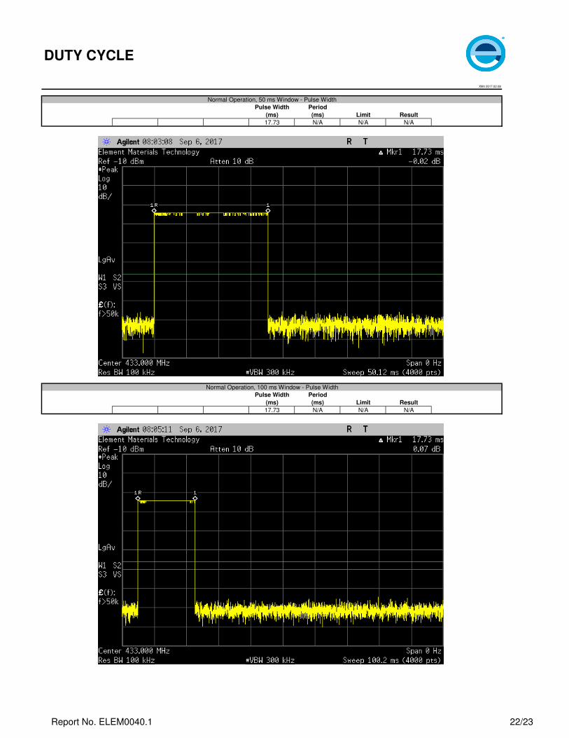
Pulse Width Period
(ms) (ms) Limit Result
Normal Operation
50 ms Window - Pulse Width 17.73 N/A N/A N/A
100 ms Window - Pulse Width 17.73 N/A N/A N/A
500 ms Window - Period N/A 98.43 N/A N/A
10 s Window N/A N/A N/A N/A
DUTY CYCLE
09/06/17
Configuration # 1
FCC 15.231:2017 ANSI C63.10:2013
None
Power Setting -6
Report No. ELEM0040.1 21/23
XMit 2017.02.08
XMit 2017.02.08
Pulse Width Period
(ms) (ms) Limit Result
17.73 N/A N/A N/A
Pulse Width Period
(ms) (ms) Limit Result
17.73 N/A N/A N/A
DUTY CYCLE
Normal Operation, 50 ms Window - Pulse Width
Normal Operation, 100 ms Window - Pulse Width
Report No. ELEM0040.1 22/23

XMit 2017.02.08
XMit 2017.02.08
Pulse Width Period
(ms) (ms) Limit Result
N/A 98.43 N/A N/A
Pulse Width Period
(ms) (ms) Limit Result
N/A N/A N/A N/A
DUTY CYCLE
Normal Operation, 500 ms Window - Period
Normal Operation, 10 s Window
Report No. ELEM0040.1 23/23