Embed Size (px)
Citation preview

Global United Technology Services Co., Ltd.
Report No.: GTS201706000291E04
The CE mark as shown below can be used, under the responsibility of the manufacturer, after completion of an EC Declaration of Conformity and compliance with all relevant EC Directives. The protection requirements with respect to electromagnetic compatibility contained in Directive 2014/53/EU are considered.
Robinson Lo
Laboratory Manager This results shown in this test report refer only to the sample(s) tested, this test report cannot be reproduced, except in full, without prior written permission of the company. The report would be invalid without specific stamp of test institute and the signatures of compiler and approver.
SPECTRUM REPORT (WIFI)
Applicant: SHENZHEN WLINK TECHNOLOGY CO., LIMITED
Address of Applicant: 319,YiBen Electronic Business Building, NO.1063 ChaGuang Road, XiLi, NanShan District, ShenZhen, China
Manufacturer: SHENZHEN WLINK TECHNOLOGY CO., LIMITED
Address of Manufacturer:
319,YiBen Electronic Business Building, NO.1063 ChaGuang Road, XiLi, NanShan District, ShenZhen, China
Equipment Under Test (EUT)
Product Name: Industrial Cellular Router
Model No.: WL-R220
Applicable standards: ETSI EN 300 328 V2.1.1 (2016-11)
Date of sample receipt: June 27, 2017
Date of Test: June 28-July 04, 2017
Date of report issue: July 05, 2017
Test Result : PASS *
* In the configuration tested, the EUT detailed in this report complied with the standards specified above.

Report No.: GTS201706000291E04
Global United Technology Services Co., Ltd. No. 301-309, 3/F., Jinyuan Business Building, No.2, Laodong Industrial Zone, Xixiang Road, Baoan District, Shenzhen, Guangdong, China 518102 Telephone: +86 (0) 755 2779 8480 Fax: +86 (0) 755 2779 8960 Page 2 of 73
2 Version
Version No. Date Description
00 July 05, 2017 Original
Prepared By:
Date: July 05, 2017
Project Engineer
Check By: Date: July 05, 2017
Reviewer

Report No.: GTS201706000291E04
Global United Technology Services Co., Ltd. No. 301-309, 3/F., Jinyuan Business Building, No.2, Laodong Industrial Zone, Xixiang Road, Baoan District, Shenzhen, Guangdong, China 518102 Telephone: +86 (0) 755 2779 8480 Fax: +86 (0) 755 2779 8960 Page 3 of 73
3 Contents Page
1 COVER PAGE ........................................................................................................................................... 1
2 VERSION .................................................................................................................................................. 2
3 CONTENTS .............................................................................................................................................. 3
4 TEST SUMMARY ..................................................................................................................................... 4
5 GENERAL INFORMATION ...................................................................................................................... 5
5.1 GENERAL DESCRIPTION OF EUT ......................................................................................................... 5 5.2 TEST MODE ........................................................................................................................................ 6 5.3 TEST FACILITY .................................................................................................................................... 7 5.4 TEST LOCATION ................................................................................................................................. 7 5.5 DESCRIPTION OF SUPPORT UNITS ....................................................................................................... 7 5.6 DEVIATION FROM STANDARDS ............................................................................................................. 7 5.7 ABNORMALITIES FROM STANDARD CONDITIONS ................................................................................... 7 5.8 OTHER INFORMATION REQUESTED BY THE CUSTOMER ......................................................................... 7
6 TEST INSTRUMENTS LIST ..................................................................................................................... 8
7 RADIO TECHNICAL SPECIFICATION IN ETSI EN 300 328 ................................................................ 10
7.1 TEST ENVIRONMENT AND MODE ........................................................................................................ 10 7.2 TRANSMITTER REQUIREMENT ............................................................................................................ 11
7.2.1 RF Output Power ....................................................................................................................... 11 7.2.2 Power Spectral Density ............................................................................................................. 21 7.2.3 Adaptivity ................................................................................................................................... 28 7.2.4 Occupied Channel Bandwidth ................................................................................................... 45 7.2.5 Transmitter unwanted emissions in the OOB domain ............................................................... 51 7.2.6 Transmitter unwanted emissions in the spurious domain ......................................................... 55
7.3 RECEIVER REQUIREMENT.................................................................................................................. 63 7.3.1 Spurious Emissions ................................................................................................................... 63 7.3.2 Receiver Blocking ...................................................................................................................... 70
8 TEST SETUP PHOTO ............................................................................................................................ 73
9 EUT CONSTRUCTIONAL DETAILS ..................................................................................................... 73

Report No.: GTS201706000291E04
Global United Technology Services Co., Ltd. No. 301-309, 3/F., Jinyuan Business Building, No.2, Laodong Industrial Zone, Xixiang Road, Baoan District, Shenzhen, Guangdong, China 518102 Telephone: +86 (0) 755 2779 8480 Fax: +86 (0) 755 2779 8960 Page 4 of 73
4 Test Summary Radio Spectrum Matter (RSM) Part of Tx
Test Test Requirement Test method Limit/Severity Uncertainty Result RF Output Power Clause 4.3.2.2 Clause 5.4.2.2 20dBm ±1.5dB PASS Power Spectral Density Clause 4.3.2.3 Clause 5.4.3.2 10dBm/MHz ±3dB PASS
Duty Cycle, Tx-sequence, Tx-gap Clause 4.3.2.4 Clause
5.4.2.2.1.3 Clause
4.3.2.4.3 ±5 % N/A
Medium Utilisation (MU) factor Clause 4.3.2.5 Clause
5.4.2.2.1.4 ≤ 10% ±5 % N/A
Adaptivity Clause 4.3.2.6 Clause 5.4.6.2
Clause 4.3.2.6.2.2 &
Clause 4.3.2.6.3.2 &
Clause 4.3.2.6.4.2
-- PASS
Occupied Channel Bandwidth Clause 4.3.2.7 Clause 5.4.7.2 Clause
4.3.2.7.3 ±5 % PASS
Transmitter unwanted emissions in the OOB domain
Clause 4.3.2.8 Clause 5.4.8.2 Clause 4.3.2.8.3 ±3dB PASS
Transmitter unwanted emissions in the spurious domain
Clause 4.3.2.9 Clause 5.4.9.2 Clause 4.3.2.9.3 ±6dB PASS
Radio Spectrum Matter (RSM) Part of Rx Receiver spurious emissions Clause 4.3.2.10 Clause 5.4.10.2 Clause
4.3.2.10.3 ±6dB PASS
Receiver Blocking Clause 4.3.2.11 Clause 5.4.11.2 Clause 4.3.2.11.4 -- PASS
Geo-location capability Clause 4.3.2.12 -- -- -- N/A
Remark: The EUT belongs to receiver category 1. Tx: In this whole report Tx (or tx) means Transmitter. Rx: In this whole report Rx (or rx) means Receiver. Temperature (Uncertainty): ±1°C Humidity(Uncertainty): ±5% Uncertainty: ± 3%(for DC and low frequency voltages)

Report No.: GTS201706000291E04
Global United Technology Services Co., Ltd. No. 301-309, 3/F., Jinyuan Business Building, No.2, Laodong Industrial Zone, Xixiang Road, Baoan District, Shenzhen, Guangdong, China 518102 Telephone: +86 (0) 755 2779 8480 Fax: +86 (0) 755 2779 8960 Page 5 of 73
5 General Information 5.1 General Description of EUT
Product Name: Industrial Cellular Router
Model No.: WL-R220
Operation Frequency: 2412MHz~2472MHz(802.11b/802.11g/802.11n(H20)) 2422MHz~2462MHz(802.11n(H40))
Channel numbers: 13 for 802.11b/802.11g/802.11n(HT20) 9 for 802.11n(HT40)
Channel separation: 5MHz
Modulation Technology: (IEEE 802.11b)
Direct Sequence Spread Spectrum(DSSS)
Modulation Technology: (IEEE 802.11g/802.11n)
Orthogonal Frequency Division Multiplexing(OFDM)
Antenna Type: Integral Antenna
Antenna gain: 1.0dBi (declare by Applicant) Power Supply: Adapter
Model No.: TS-A018-120015EJ Input: AC 100-240V, 50/60Hz, 0.5A Output: DC 12V, 1.5A
Report No.: GTS201706000291E04
Global United Technology Services Co., Ltd. No. 301-309, 3/F., Jinyuan Business Building, No.2, Laodong Industrial Zone, Xixiang Road, Baoan District, Shenzhen, Guangdong, China 518102 Telephone: +86 (0) 755 2779 8480 Fax: +86 (0) 755 2779 8960 Page 6 of 73
WIFI Operation Frequency each of channel
Channel Frequency Channel Frequency Channel Frequency Channel Frequency
1 2412MHz 5 2432MHz 9 2452MHz 13 2472MHz
2 2417MHz 6 2437MHz 10 2457MHz
3 2422MHz 7 2442MHz 11 2462MHz
4 2427MHz 8 2447MHz 12 2467MHz The EUT operation in above frequency list, and used test software to control the EUT for staying in continuous transmitting and receiving mode. So test frequency is below:
Test channel Frequency (MHz)
802.11b/802.11g/802.11n(HT20) 802.11n(HT40)
Lowest channel 2412MHz 2422MHz
Middle channel 2442MHz 2442MHz
Highest channel 2472MHz 2462MHz
5.2 Test mode Transmitting mode Keep the EUT in continuously transmitting mode. Receiving mode Keep the EUT in receiving mode.
We have verified the construction and function in typical operation. All the test modes were carried out with the EUT in transmitting operation, which was shown in this test report and defined as follows: Per-scan all kind of data rate in lowest channel, and found the follow list which it was worst case.
Mode 802.11b 802.11g 802.11n(HT20) 802.11n(HT40) Data rate 1Mbps 6Mbps 6.5Mbps 13Mbps

Report No.: GTS201706000291E04
Global United Technology Services Co., Ltd. No. 301-309, 3/F., Jinyuan Business Building, No.2, Laodong Industrial Zone, Xixiang Road, Baoan District, Shenzhen, Guangdong, China 518102 Telephone: +86 (0) 755 2779 8480 Fax: +86 (0) 755 2779 8960 Page 7 of 73
5.3 Test Facility The test facility is recognized, certified, or accredited by the following organizations: ● FCC —Registration No.: 600491 Global United Technology Services Co., Ltd., Shenzhen EMC Laboratory has been registered and fuly described in a report filed with the (FCC) Federal Communications Commission. The acceptance letter from the FCC is maintained in files. Registration 600491, June 22, 2016. ● Industry Canada (IC) —Registration No.: 9079A-2 The 3m Semi-anechoic chamber of Global United Technology Services Co., Ltd. Has been Registered by Certification and Engineering Bureau of Industry Canada for radio equipment testing with Registration No.: 9079A-2, August 15, 2016.
5.4 Test Location All tests were performed at: Global United Technology Services Co., Ltd. Address: No. 301-309, 3/F., Jinyuan Business Building, No.2, Laodong Industrial Zone, Xixiang Road, Baoan District, Shenzhen, Guangdong, China 518102 Tel: 0755-27798480 Fax: 0755-27798960
5.5 Description of Support Units The EUT has been tested as an independent unit.
5.6 Deviation from Standards None.
5.7 Abnormalities from Standard Conditions None.
5.8 Other Information Requested by the Customer None.

Report No.: GTS201706000291E04
Global United Technology Services Co., Ltd. No. 301-309, 3/F., Jinyuan Business Building, No.2, Laodong Industrial Zone, Xixiang Road, Baoan District, Shenzhen, Guangdong, China 518102 Telephone: +86 (0) 755 2779 8480 Fax: +86 (0) 755 2779 8960 Page 8 of 73
6 Test Instruments List Radiated Emission:
Item Test Equipment Manufacturer Model No. Inventory No.
Cal.Date (mm-dd-yy)
Cal.Due date (mm-dd-yy)
1 3m Semi- Anechoic Chamber ZhongYu Electron 9.0(L)*6.0(W)* 6.0(H) GTS250 July. 03 2015 July. 02 2020
2 Control Room ZhongYu Electron 6.2(L)*2.5(W)* 2.4(H) GTS251 N/A N/A 3 ESU EMI Test Receiver R&S ESU26 GTS203 June. 28 2017 June. 27 2018 4 BiConiLog Antenna SCHWARZBECK VULB9163 GTS214 June. 28 2017 June. 27 2018
5 Double-ridged horn antenna SCHWARZBECK 9120D GTS208 June. 28 2017 June. 27 2018
6 Horn Antenna ETS-LINDGREN 3160-09 GTS218 June. 28 2017 June. 27 2018 7 RF Amplifier HP 8347A GTS204 June. 28 2017 June. 27 2018 8 RF Amplifier HP 8349B GTS206 June. 28 2017 June. 27 2018
9 Broadband Preamplifier
SCHWARZBECK BBV9718 GTS535 June. 28 2017 June. 27 2018
10 PSA Series Spectrum Analyzer Agilent E4440A GTS536 June. 28 2017 June. 27 2018
11 Universal Radio Communication tester ROHDE&SCHWARZ CMU 200 GTS538 June. 28 2017 June. 27 2018
12 EMI Test Software AUDIX E3 N/A N/A N/A 13 Coaxial cable GTS N/A GTS210 N/A N/A 14 Coaxial Cable GTS N/A GTS211 N/A N/A 15 Thermo meter N/A N/A GTS256 June. 28 2017 June. 27 2018

Report No.: GTS201706000291E04
Global United Technology Services Co., Ltd. No. 301-309, 3/F., Jinyuan Business Building, No.2, Laodong Industrial Zone, Xixiang Road, Baoan District, Shenzhen, Guangdong, China 518102 Telephone: +86 (0) 755 2779 8480 Fax: +86 (0) 755 2779 8960 Page 9 of 73
Conducted:
Item Test Equipment Manufacturer Model No. Serial No. Cal.Date (mm-dd-yy)
Cal.Due date (mm-dd-yy)
1 Signal Analyzer Agilent N9010A MY48030494 June. 29 2016 June. 28 2017
2 vector Signal Generator Agilent E4438C MY49070163 June. 29 2016 June. 28 2017
3 splitter Mini-Circuits ZAP-50W NN256400424 June. 29 2016 June. 28 2017 4 Directional Coupler Agilent 87300C MY44300299 June. 29 2016 June. 28 2017
5 vector Signal Generator Agilent E4438C US44271917 June. 29 2016 June. 28 2017
6 X-series USB Peak and Average Power
Sensor Agilent U2021XA MY54080020 June. 29 2016 June. 28 2017
7 X-series USB Peak and Average Power
Sensor Agilent U2021XA MY54110001 June. 29 2016 June. 28 2017
8 X-series USB Peak and Average Power
Sensor Agilent U2021XA MY53480008 June. 29 2016 June. 28 2017
9 X-series USB Peak and Average Power
Sensor Agilent U2021XA MY54080019 June. 29 2016 June. 28 2017
10 4 Ch.Simultaneous Sampling 14 Bits 2
MS/s Agilent U2531A TW54063507 June. 29 2016 June. 28 2017
11 4 Ch.Simultaneous Sampling 14 Bits 2
MS/s Agilent U2531A TW54063513 June. 29 2016 June. 28 2017
12 splitter Mini PS3-7 4463 June. 29 2016 June. 28 2017

Report No.: GTS201706000291E04
Global United Technology Services Co., Ltd. No. 301-309, 3/F., Jinyuan Business Building, No.2, Laodong Industrial Zone, Xixiang Road, Baoan District, Shenzhen, Guangdong, China 518102 Telephone: +86 (0) 755 2779 8480 Fax: +86 (0) 755 2779 8960 Page 10 of 73
7 Radio Technical Specification in ETSI EN 300 328 7.1 Test Environment and Mode Test mode: Transmitting mode: Keep the EUT in transmitting mode with modulation. Receiving mode Keep the EUT in receiving mode.
Operating Environment:
Item Normal condition
Extreme condition NVHT NVLT
Temperature +25ºC +45ºC 0ºC
Humidity 20%-95% Atmospheric
Pressure: 1008 mbar
Setting Value
Modulation Other Adaptive Yes Antenna Gain 1 1.0dBi Nominal Channel Bandwidth 20MHz/40MHz DUT Frequency not configurable No Frequency Low 2412MHz/2422MHz Frequency Mid 2442MHz Frequency High 2472MHz/2462MHz

Report No.: GTS201706000291E04
Global United Technology Services Co., Ltd. No. 301-309, 3/F., Jinyuan Business Building, No.2, Laodong Industrial Zone, Xixiang Road, Baoan District, Shenzhen, Guangdong, China 518102 Telephone: +86 (0) 755 2779 8480 Fax: +86 (0) 755 2779 8960 Page 11 of 73
7.2 Transmitter Requirement 7.2.1 RF Output Power
Test Requirement: ETSI EN 300 328 clause 4.3.2.2 Test Method: ETSI EN 300 328 clause 5.4.2.2.1.2 Limit: 20dBm Test setup:
Test procedure: Step 1:
Use a fast power sensor suitable for 2,4 GHz and capable of 1 MS/s. Use the following settings: - Sample speed 1 MS/s or faster. - The samples must represent the power of the signal. - Measurement duration: For non-adaptive equipment: equal to the observation period defined in clauses 4.3.1.3.2 or 4.3.2.4.2. For adaptive equipment, the measurement duration shall be long enough to ensure a minimum number of bursts (at least 10) are captured. For adaptive equipment, to increase the measurement accuracy, a higher number of bursts may be used. Step 2: For conducted measurements on devices with one transmit chain: -Connect the power sensor to the transmit port, sample the transmit signal and store the raw data.Use these stored samples in all following steps. For conducted measurements on devices with multiple transmit chains: -Connect one power sensor to each transmit port for a synchronous measurement on all transmit ports. -Trigger the power sensors so that they start sampling at the same time. Make sure the time difference between the samples of all sensors is less than 500ns. -For each individual smpling point(time domain), sum the coincident power samples of all ports and store them. Use these summed samples in all following steps. Step 3: Find the start and stop times of each burst in the stored measurement samples. The start and stop times are defined as the points where the power is at least 30 dB below the highest value of the stored samples in step 2. In case of insufficient dynamic range,the value of 30dB may need to be

Report No.: GTS201706000291E04
Global United Technology Services Co., Ltd. No. 301-309, 3/F., Jinyuan Business Building, No.2, Laodong Industrial Zone, Xixiang Road, Baoan District, Shenzhen, Guangdong, China 518102 Telephone: +86 (0) 755 2779 8480 Fax: +86 (0) 755 2779 8960 Page 12 of 73
reduced appropriately. Step 4: Between the start and stop times of each individual burst calculate the RMS power over the burst using the formula below. Save these Pburst values, as well as the start and stop times for each burst.
With “k” being the total number of samples and “n” the actual sample number Step 5: The highest of all Pburst values (value "A" in dBm) will be used for maximum e.i.r.p. calculations. Step 6: Add the (stated) antenna assembly gain "G" in dBi of the individual antenna. If applicable, add the additional beamforming gain "Y" in dB. If more than one antenna assembly is intended for this power setting, the maximum overall antenna gain (G or G + Y) shall be used. The RF Output Power (P) shall be calculated using the formula below: P = A + G + Y Step 7: This value, which shall comply with the limit given in clause 4.3.1.2.3 or clause 4.3.2.2.3, shall be recorded in the test report.
Measurement Record: Uncertainty: ± 1.5dB Test Instruments: See section 6.0 Test mode: Transmitting mode

Report No.: GTS201706000291E04
Global United Technology Services Co., Ltd. No. 301-309, 3/F., Jinyuan Business Building, No.2, Laodong Industrial Zone, Xixiang Road, Baoan District, Shenzhen, Guangdong, China 518102 Telephone: +86 (0) 755 2779 8480 Fax: +86 (0) 755 2779 8960 Page 13 of 73
Measurement Data ANT 1
802.11b mode
Test conditions Channel Burst RMS power (dBm)
Antenna Gain(dBi)
Calculated Power (dBm)
Limit (dBm) Result
Normal Lowest 15.21 1.00 16.21
20 Pass
Middle 15.33 1.00 16.33 Highest 15.52 1.00 16.52
NVHT Lowest 15.14 1.00 16.14 Middle 15.23 1.00 16.23 Highest 15.42 1.00 16.42
NVLT Lowest 15.19 1.00 16.19 Middle 15.31 1.00 16.31 Highest 15.50 1.00 16.50
802.11g mode
Test conditions Channel Burst RMS power (dBm)
Antenna Gain(dBi)
Calculated Power (dBm)
Limit (dBm) Result
Normal Lowest 13.27 1.00 14.27
20 Pass
Middle 13.38 1.00 14.38 Highest 13.20 1.00 14.20
NVHT Lowest 13.20 1.00 14.20 Middle 13.28 1.00 14.28 Highest 13.10 1.00 14.10
NVLT Lowest 13.25 1.00 14.25 Middle 13.36 1.00 14.36 Highest 13.18 1.00 14.18

Report No.: GTS201706000291E04
Global United Technology Services Co., Ltd. No. 301-309, 3/F., Jinyuan Business Building, No.2, Laodong Industrial Zone, Xixiang Road, Baoan District, Shenzhen, Guangdong, China 518102 Telephone: +86 (0) 755 2779 8480 Fax: +86 (0) 755 2779 8960 Page 14 of 73
802.11n(HT20) mode
Test conditions Channel Burst RMS power (dBm)
Antenna Gain(dBi)
Calculated Power (dBm)
Limit (dBm) Result
Normal Lowest 12.86 1.00 13.86
20 Pass
Middle 12.98 1.00 13.98 Highest 12.55 1.00 13.55
NVHT Lowest 12.79 1.00 13.79 Middle 12.88 1.00 13.88 Highest 12.45 1.00 13.45
NVLT Lowest 12.84 1.00 13.84 Middle 12.96 1.00 13.96 Highest 12.53 1.00 13.53
802.11n(HT40) mode
Test conditions Channel Burst RMS power (dBm)
Antenna Gain(dBi)
Calculated Power (dBm)
Limit (dBm) Result
Normal Lowest 10.24 1.00 11.24
20 Pass
Middle 10.42 1.00 11.42 Highest 10.15 1.00 11.15
NVHT Lowest 10.17 1.00 11.17 Middle 10.32 1.00 11.32 Highest 10.05 1.00 11.05
NVLT Lowest 10.22 1.00 11.22 Middle 10.40 1.00 11.40 Highest 10.13 1.00 11.13
Remark:1>. Volt= Voltage, Temp= Temperature 2>. Duty cycle=100%, Antenna Gain=1.0dBi

Report No.: GTS201706000291E04
Global United Technology Services Co., Ltd. No. 301-309, 3/F., Jinyuan Business Building, No.2, Laodong Industrial Zone, Xixiang Road, Baoan District, Shenzhen, Guangdong, China 518102 Telephone: +86 (0) 755 2779 8480 Fax: +86 (0) 755 2779 8960 Page 15 of 73
ANT 2
802.11b mode
Test conditions Channel Burst RMS power (dBm)
Antenna Gain(dBi)
Calculated Power (dBm)
Limit (dBm) Result
Normal Lowest 15.05 1.00 16.05
20 Pass
Middle 15.21 1.00 16.21 Highest 15.44 1.00 16.44
NVHT Lowest 14.98 1.00 15.98 Middle 15.11 1.00 16.11 Highest 15.34 1.00 16.34
NVLT Lowest 15.03 1.00 16.03 Middle 15.19 1.00 16.19 Highest 15.42 1.00 16.42
802.11g mode
Test conditions Channel Burst RMS power (dBm)
Antenna Gain(dBi)
Calculated Power (dBm)
Limit (dBm) Result
Normal Lowest 13.07 1.00 14.07
20 Pass
Middle 13.16 1.00 14.16 Highest 13.30 1.00 14.30
NVHT Lowest 13.00 1.00 14.00 Middle 13.06 1.00 14.06 Highest 13.20 1.00 14.20
NVLT Lowest 13.05 1.00 14.05 Middle 13.14 1.00 14.14 Highest 13.28 1.00 14.28

Report No.: GTS201706000291E04
Global United Technology Services Co., Ltd. No. 301-309, 3/F., Jinyuan Business Building, No.2, Laodong Industrial Zone, Xixiang Road, Baoan District, Shenzhen, Guangdong, China 518102 Telephone: +86 (0) 755 2779 8480 Fax: +86 (0) 755 2779 8960 Page 16 of 73
802.11n(HT20) mode
Test conditions Channel Burst RMS power (dBm)
Antenna Gain(dBi)
Calculated Power (dBm)
Limit (dBm) Result
Normal Lowest 12.68 1.00 13.68
20 Pass
Middle 12.95 1.00 13.95 Highest 12.45 1.00 13.45
NVHT Lowest 12.61 1.00 13.61 Middle 12.85 1.00 13.85 Highest 12.35 1.00 13.35
NVLT Lowest 12.66 1.00 13.66 Middle 12.93 1.00 13.93 Highest 12.43 1.00 13.43
802.11n(HT40) mode
Test conditions Channel Burst RMS power (dBm)
Antenna Gain(dBi)
Calculated Power (dBm)
Limit (dBm) Result
Normal Lowest 10.35 1.00 11.35
20 Pass
Middle 10.64 1.00 11.64 Highest 10.20 1.00 11.20
NVHT Lowest 10.28 1.00 11.28 Middle 10.54 1.00 11.54 Highest 10.10 1.00 11.10
NVLT Lowest 10.33 1.00 11.33 Middle 10.62 1.00 11.62 Highest 10.18 1.00 11.18
Remark:1>. Volt= Voltage, Temp= Temperature 2>. Duty cycle=100%, Antenna Gain=1.0dBi

Report No.: GTS201706000291E04
Global United Technology Services Co., Ltd. No. 301-309, 3/F., Jinyuan Business Building, No.2, Laodong Industrial Zone, Xixiang Road, Baoan District, Shenzhen, Guangdong, China 518102 Telephone: +86 (0) 755 2779 8480 Fax: +86 (0) 755 2779 8960 Page 17 of 73
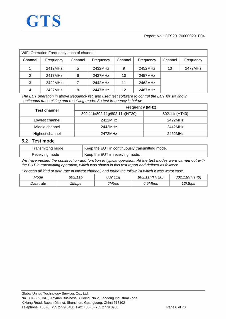
Test plots at normal condition are below: Test mode: 802.11b
Lowest Channel
Middle Channel
Highest Channel
Report No.: GTS201706000291E04
Global United Technology Services Co., Ltd. No. 301-309, 3/F., Jinyuan Business Building, No.2, Laodong Industrial Zone, Xixiang Road, Baoan District, Shenzhen, Guangdong, China 518102 Telephone: +86 (0) 755 2779 8480 Fax: +86 (0) 755 2779 8960 Page 18 of 73
Test mode: 802.11g
Lowest Channel
Middle Channel
Highest Channel

Report No.: GTS201706000291E04
Global United Technology Services Co., Ltd. No. 301-309, 3/F., Jinyuan Business Building, No.2, Laodong Industrial Zone, Xixiang Road, Baoan District, Shenzhen, Guangdong, China 518102 Telephone: +86 (0) 755 2779 8480 Fax: +86 (0) 755 2779 8960 Page 19 of 73
Test mode: 802.11n-HT20
Lowest Channel
Middle Channel
Highest Channel

Report No.: GTS201706000291E04
Global United Technology Services Co., Ltd. No. 301-309, 3/F., Jinyuan Business Building, No.2, Laodong Industrial Zone, Xixiang Road, Baoan District, Shenzhen, Guangdong, China 518102 Telephone: +86 (0) 755 2779 8480 Fax: +86 (0) 755 2779 8960 Page 20 of 73
Test mode: 802.11n-HT40
Lowest Channel
Middle Channel
Highest Channel

Report No.: GTS201706000291E04
Global United Technology Services Co., Ltd. No. 301-309, 3/F., Jinyuan Business Building, No.2, Laodong Industrial Zone, Xixiang Road, Baoan District, Shenzhen, Guangdong, China 518102 Telephone: +86 (0) 755 2779 8480 Fax: +86 (0) 755 2779 8960 Page 21 of 73
7.2.2 Power Spectral Density
Test Requirement: ETSI EN 300 328 clause 4.3.2.3 Test Method: ETSI EN 300 328 clause 5.4.3.2.1 Limit: 10dBm/MHz Test setup:
Test procedure: Step 1: Connect the UUT to the spectrum analyser and use the following settings:
Start Frequency: 2400 MHz Stop Frequency: 2483.5 MHz Resolution BW: 10 kHz Video BW: 30 kHz Sweep Points: > 8350 For spectrum analysers not supporting this number of sweep points, the frequency band may be segmented. Detector: RMS Trace Mode: Max Hold Sweep time: 10s; the sweep time may be increased further
until a value where the sweep time has no impact on the RMS value of the signal
For non-continuous signals, wait for the trace to stabilize. Save the (trace data) set to a file. Step 2: For conducted measurements on smart antenna systems using either operating mode 2 or 3 (see clause 5.3.2.2), repeat the measurement for each of the transmit ports. For each sampling point(frequency domain) , add up the coincident power values(in mW) for the different transmit chains and use this as the new data set. Step 3: Add up the values for power for all the samples in the file using the formula below.
With “k” being the total number of samples and “n” the actual sample
Number. Step 4: Normalize the individual values for power(in dBm) so that the sum is equal to the RF output Power (e.i.r.p.) measured in clause 5.4.2 and save the

Report No.: GTS201706000291E04
Global United Technology Services Co., Ltd. No. 301-309, 3/F., Jinyuan Business Building, No.2, Laodong Industrial Zone, Xixiang Road, Baoan District, Shenzhen, Guangdong, China 518102 Telephone: +86 (0) 755 2779 8480 Fax: +86 (0) 755 2779 8960 Page 22 of 73
corrected data. The following formulas can be used:
With”n” being the actual sample number Step 5: Starting from the first sample Psamplecorr(n) (lowest frequency), add up the power(in mW) of the following samples representing a 1 MHz segment and record the results for power and position (i.e. sample #1 to #100). This is the Power Spectral Density (e.i.r.p.) for the first 1 MHz segment which shall be recorded. Step 6: Shift the start point of the samples added up in step 5 by one sample and repeat the procedure in step 5 (i.e. sample #2 to #101). Step 7: Repeat step 6 until the end of the data set and record the Power Spectral Density values for each of the 1 MHz segments. From all the recorded results, the highest value is the maximum Power Spectral Density for the UUT. This value, which shall comply with the limit given in clause 4.3.2.3.3,shall be recorded in the test report.
Measurement Record: Uncertainty: ±3dB Test Instruments: See section 6.0 Test mode: Transmitting mode

Report No.: GTS201706000291E04
Global United Technology Services Co., Ltd. No. 301-309, 3/F., Jinyuan Business Building, No.2, Laodong Industrial Zone, Xixiang Road, Baoan District, Shenzhen, Guangdong, China 518102 Telephone: +86 (0) 755 2779 8480 Fax: +86 (0) 755 2779 8960 Page 23 of 73
Measurement Data Remark: Each antenna was tested, and the data of ANT1 is worst. So only the data of ANT1 is reported.
802.11b mode Channel Power Spectral Density (dBm/MHz) Limit (dBm/MHz) Result CH 1 8.65
10.00 Pass CH 7 8.76 CH 13 8.79
802.11g mode Channel Power Spectral Density (dBm/MHz) Limit (dBm/MHz) Result CH 1 3.10
10.00 Pass CH 7 4.75 CH 13 4.14
802.11n-HT20 mode Channel Power Spectral Density (dBm/MHz) Limit (dBm/MHz) Result CH 1 3.25
10.00 Pass CH 7 4.56 CH 13 4.05
802.11n-HT40 mode Channel Power Spectral Density (dBm/MHz) Limit (dBm/MHz) Result CH 3 -2.73
10.00 Pass CH 7 -0.58 CH 11 -0.94

Report No.: GTS201706000291E04
Global United Technology Services Co., Ltd. No. 301-309, 3/F., Jinyuan Business Building, No.2, Laodong Industrial Zone, Xixiang Road, Baoan District, Shenzhen, Guangdong, China 518102 Telephone: +86 (0) 755 2779 8480 Fax: +86 (0) 755 2779 8960 Page 24 of 73
Test plots are followed: 802.11b mode

Report No.: GTS201706000291E04
Global United Technology Services Co., Ltd. No. 301-309, 3/F., Jinyuan Business Building, No.2, Laodong Industrial Zone, Xixiang Road, Baoan District, Shenzhen, Guangdong, China 518102 Telephone: +86 (0) 755 2779 8480 Fax: +86 (0) 755 2779 8960 Page 25 of 73
802.11g mode

Report No.: GTS201706000291E04
Global United Technology Services Co., Ltd. No. 301-309, 3/F., Jinyuan Business Building, No.2, Laodong Industrial Zone, Xixiang Road, Baoan District, Shenzhen, Guangdong, China 518102 Telephone: +86 (0) 755 2779 8480 Fax: +86 (0) 755 2779 8960 Page 26 of 73
802.11n-HT20 mode

Report No.: GTS201706000291E04
Global United Technology Services Co., Ltd. No. 301-309, 3/F., Jinyuan Business Building, No.2, Laodong Industrial Zone, Xixiang Road, Baoan District, Shenzhen, Guangdong, China 518102 Telephone: +86 (0) 755 2779 8480 Fax: +86 (0) 755 2779 8960 Page 27 of 73
802.11n-HT40 mode

Report No.: GTS201706000291E04
Global United Technology Services Co., Ltd. No. 301-309, 3/F., Jinyuan Business Building, No.2, Laodong Industrial Zone, Xixiang Road, Baoan District, Shenzhen, Guangdong, China 518102 Telephone: +86 (0) 755 2779 8480 Fax: +86 (0) 755 2779 8960 Page 28 of 73
7.2.3 Adaptivity
Test Requirement: ETSI EN 300 328 clause 4.3.2.6 Test Method: ETSI EN 300 328 clause 5.3.7.2.1 Limit: Clause 4.3.2.6.2.2 & Clause 4.3.2.6.3.2 & Clause 4.3.2.6.4.2 Test setup:
Test procedure: 1. Adaptive Frequency Hopping equipment using DAA The different steps below define the procedure to verify the efficiency of the DAA based adaptive mechanisms for frequency hopping equipment. These mechanisms are described in clause 4.3.1.7. For systems using multiple receive chains only one chain (antenna port) need to be tested. All other receiver inputs shall be terminated. Step 1: The UUT may connect to a companion device during the test. The interference signal generator, the blocking signal generator, the spectrum analyser, the UUT and the companion device are connected using a set-up equivalent to the example given by figure 5, although the interference and blocking signal generators do not generate any signals at this point in time. The spectrum analyser is used to monitor the transmissions of the UUT in response to the interfering and the blocking signals. For the hopping frequency to be tested, adjust the received signal level (wanted signal from the companion device) at the UUT to the value defined in table 2 and table 3 (clause 4). Testing of Unidirectional equipment does not require a link to be established with a companion device. The analyzer shall be set as follows:
RBW: use next available RBW setting below the measured Occupied Channel Bandwidth
Filter type: Channel Filter VBW: ≥ RBW Detector Mode: RMS

Report No.: GTS201706000291E04
Global United Technology Services Co., Ltd. No. 301-309, 3/F., Jinyuan Business Building, No.2, Laodong Industrial Zone, Xixiang Road, Baoan District, Shenzhen, Guangdong, China 518102 Telephone: +86 (0) 755 2779 8480 Fax: +86 (0) 755 2779 8960 Page 29 of 73
Centre Frequency: Equal to the hopping frequency to be tested Span: 0Hz Sweep time: >Channel Occupancy Time of the UUT. If the
Channel Occupancy Time is non-contiguous (non-LBT based equipment), the sweep time shall be sufficient to cover the period over which the Channel Occupancy Time is spread out.
Trace Mode: Clear/Write Trigger Mode: Video
Step 2: Configure the UUT for normal transmissions with a sufficiently high payload to resulting in a minimum transmitter activity ratio(TxOn+TxOff)) of 0.3.Where this is not possible, the UUT shall be configured to the maximum payload possible. Using the procedure defined in clause 5.4.6.2.1.5, it shall be verified that, for equipment with a dwell time greater than the maximum allowable Channel Occupancy Time, the UUT complies with the maximum Channel Occupancy Time and minimum Idle Period defined in clauses 4.3.1.7.2.2 and 4.3.1.7.3.2. Step 3: Adding the interference signal An interference signal as defined in clause B.6 is injected centred on the hopping frequency being tested. The Power Spectral Density level(at the input of the UUT) of this interference signal shall be equal to the detection threshold defined in clauses 4.3.1.7.2.2 or 4.3.1.7.3.2. Step 4: Verification of reaction to the interference signal The spectrum analyser shall be used to monitor the transmissions of the UUT on the selected hopping frequency with the interfering signal injected. This may require the spectrum analyser sweep to be triggered by the start of the interfering signal. Using the procedure defined in clause 5.4.6.2.1.5, it shall be verified that:
i) The UUT shall stop transmissions on the hopping frequency being tested. The UUT is assumed to stop transmissions on this hopping frequency within a period equal to the maximum Channel Occupancy Time defined in clauses 4.3.1.7.2.2 or clause 4.3.1.7.3.2 As stated in clause 4.3.1.7.3.2, the Channel Occupancy Time for non-LBT based frequency hopping systems may be non-contiguous. ii) For LBT based frequency hopping equipment, apart from Short Control Signalling Transmissions (see iii) below), there shall be no subsequent transmissions on this hopping frequency, as long as the interference signal remains present. For non-LBT based frequency hopping equipment, apart from Short Control Signalling Transmissions (see iii) below), there shall be no subsequent transmissions on this hopping frequency for a (silent) period defined in clause 4.3.1.7.3.2 step 2. After that, the UUT may have normal transmissions again for the duration of a single Channel Occupancy Time period (which may be non-contiguous). Because the interference signal is still present, another silent period as defined in clause 4.3.1.7.3.2 step 2 needs to be included. This sequence is

Report No.: GTS201706000291E04
Global United Technology Services Co., Ltd. No. 301-309, 3/F., Jinyuan Business Building, No.2, Laodong Industrial Zone, Xixiang Road, Baoan District, Shenzhen, Guangdong, China 518102 Telephone: +86 (0) 755 2779 8480 Fax: +86 (0) 755 2779 8960 Page 30 of 73
repeated as long as the interfering signal is present. In case of overlapping channels, transmissions in adjacent channels may generate transmission bursts on the channel being investigated, however they will have a lower amplitude as on-channel transmissions. Care should be taken to only evaluate the on-channel transmissions. The Time Domain Power Option of the analyser may be used to measure the RMS power of the individual bursts to distinguish on-channel transmissions from transmissions on adjacent channels. In some cases, the RBW may need to be reduced. To verify that the UUT is not resuming normal transmissions as long as the interference signal is present,the monitoring time may need to be 60s or more. iii) The UUT may continue to have Short Control Signalling Transmissions on the hopping frequency being tested while the interference signal is present. These transmissions shall comply with the limits defined in clause 4.3.1.7.4.2. The verification of the Short Control Signalling transmissions may require the analyser settings to be changed (e.g. sweep time). iv) Alternatively, the equipment may switch to a non-adaptive mode.
Step 5: Adding the unwanted signal With the interfering signal present, a 100 % duty cycle CW signal is inserted as the unwanted signal. The frequency and the level are provided in table 2 of clause 4.3.1.7.2.2, step 6 or table 3 of clause 4.3.1.7.3.2,step 6. The spectrum analyser shall be used to monitor the transmissions of the UUT on the selected hopping frequency. This may require the spectrum analyser sweep to be triggered by the start of the unwanted signal. Using the procedure defined in clause 5.4.6.2.1.5, it shall be verified that:
i) The UUT shall not resume normal transmissions on the hopping frequecy being tested as long as both the interference and unwanted signals remain present
To verify that the UUT is not resuming normal transmissions as long as the interference and blocking signals are present, the monitoring time may need to be 60s or more. If transmissions are detected during this period, the settings of the analyser may need to be adjusted to allow an accurate assessment to verify the transmissions comply with the limits for Short Control Signalling Transmissions.
ii) The UUT may continue to have Short Control Signalling Transmissions on the hopping frequency being tested while the interference and unwanted signal are present.These transmissions shall comply with the limits defined in clause 4.3.1.7.4.2
The verification of the Short Control Signalling transmissions may require the analyser settings to be changed(e.g.sweep time).
Step 6: Removing the interference and unwanted signal On removal of the interference and unwanted signal,the UUT is allowed to re-include any channel previously marked as unavailable; however, for non-LBT based equipment, it shall be verified that this shall only be done after the period defined in clause 4.3.1.7.3.2 point 2. Step 7: The steps 2 to 6 shall be repeated for each of the hopping frequencies to be tested.

Report No.: GTS201706000291E04
Global United Technology Services Co., Ltd. No. 301-309, 3/F., Jinyuan Business Building, No.2, Laodong Industrial Zone, Xixiang Road, Baoan District, Shenzhen, Guangdong, China 518102 Telephone: +86 (0) 755 2779 8480 Fax: +86 (0) 755 2779 8960 Page 31 of 73
2. Non-LBT based adaptive equipment using modulations other than FHSS
The different steps below define the procedure to verify the efficiency of the non-LBT based DAA adaptive mechanism of equipment using wide band modulations other than FHSS. For systems using multiple receive chains only one chain (antenna port) need to be tested. All other receiver inputs shall be terminated. Step 1: The UUT shall connect to a companion device during the test. The interference signal generator, the uwanted signal generator, the spectrum analyser, the UUT and the companion device are connected using a set-up equivalent to the example given by figure 5 although the interference and unwanted signal generator do not generate any signals at this point in time. The spectrum analyser is used to monitor the transmissions of the UUT in response to the interfering and the unwanted signals. Adjust the received signal level (wanted signal from the companion device) at the UUT to the value defined in table table 9 (clause 4.3.2.6.2.2). Testing of Unidirectional equipment does not require a link to be established with a companion device. The analyzer shall be set as follows:
RBW: ≥ Occupied Channel Bandwidth (if the analyser does not support this setting, the highest available setting s hall be used)
VBW: 3 × RBW (if the analyser does not support this setting, the highest available setting shall be used)
Detector Mode: RMS Centre Frequency: Equal to the hopping frequency to be tested Span: 0Hz Sweep time: > Channel Occupancy Time of the UUT Trace Mode: Clear/Write Trigger Mode: Video
Step 2: Configure the UUT for normal transmissions with a sufficiently high payload resulting in a minimum transmitter activity ratio (TxOn+TxOff)) of 0.3 .Where this is not possible , the UUT shall be configured to the maximum payload possible. Using the procedure defined in clause 5.3.7.2.1.4, it shall be verified that the UUT complies with the maximum Channel Occupancy Time and minimum Idle Period defined in clause 4.3.2.6.2.2. Step 3: Adding the interference signal An interference signal as defined in clause B.6 is injected centred on the current operating channel of the UUT. The Power Spectral Density level(at the input of the UUT) of this interference signal shall be equal to the detection threshold defined in clauses 4.3.2.6.2.2 step 5). Step 4: Verification of reaction to the interference signal The spectrum analyser shall be used to monitor the transmissions of the UUT on the selected operating channel with the interfering signal
Report No.: GTS201706000291E04
Global United Technology Services Co., Ltd. No. 301-309, 3/F., Jinyuan Business Building, No.2, Laodong Industrial Zone, Xixiang Road, Baoan District, Shenzhen, Guangdong, China 518102 Telephone: +86 (0) 755 2779 8480 Fax: +86 (0) 755 2779 8960 Page 32 of 73
injected. This may require the spectrum analyser sweep to be triggered bythe start of the interfering signal. Using the procedure defined in clause 5.4.6.2.1.5, it shall be verified that:
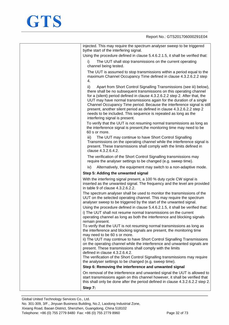
i) The UUT shall stop transmissions on the current operating channel being tested. The UUT is assumed to stop transmissions within a period equal to the maximum Channel Occupancy Time defined in clause 4.3.2.6.2.2 step 4. ii) Apart from Short Control Signalling Transmissions (see iii) below), there shall be no subsequent transmissions on this operating channel for a (silent) period defined in clause 4.3.2.6.2.2 step 2. After that, the UUT may have normal transmissions again for the duration of a single Channel Occupancy Time period. Because the interference signal is still present, another silent period as defined in clause 4.3.2.6.2.2 step 2 needs to be included. This sequence is repeated as long as the interfering signal is present. To verify that the UUT is not resuming normal transmissions as long as the interference signal is present,the monitoring time may need to be 60 s or more. iii) The UUT may continue to have Short Control Signalling Transmissions on the operating channel while the interference signal is present. These transmissions shall comply with the limits defined in clause 4.3.2.6.4.2. The verification of the Short Control Signalling transmissions may require the analyser settings to be changed (e.g. sweep time). iv) Alternatively, the equipment may switch to a non-adaptive mode.
Step 5: Adding the unwanted signal With the interfering signal present, a 100 % duty cycle CW signal is inserted as the unwanted signal. The frequency and the level are provided in table 9 of clause 4.3.2.6.2.2. The spectrum analyser shall be used to monitor the transmissions of the UUT on the selected operating channel. This may require the spectrum analyser sweep to be triggered by the start of the unwanted signal. Using the procedure defined in clause 5.4.6.2.1.5, it shall be verified that: i) The UUT shall not resume normal transmissions on the current operating channel as long as both the interference and blocking signals remain present. To verify that the UUT is not resuming normal transmissions as long as the interference and blocking signals are present, the monitoring time may need to be 60 s or more. ii) The UUT may continue to have Short Control Signalling Transmissions on the operating channel while the interference and unwanted signals are present. These transmissions shall comply with the limits defined in clause 4.3.2.6.4.2. The verification of the Short Control Signalling transmissions may require the analyser settings to be changed (e.g. sweep time). Step 6: Removing the interference and unwanted signal On removal of the interference and unwanted signal the UUT is allowed to start transmissions again on this channel however, it shall be verified that this shall only be done after the period defined in clause 4.3.2.6.2.2 step 2. Step 7:

Report No.: GTS201706000291E04
Global United Technology Services Co., Ltd. No. 301-309, 3/F., Jinyuan Business Building, No.2, Laodong Industrial Zone, Xixiang Road, Baoan District, Shenzhen, Guangdong, China 518102 Telephone: +86 (0) 755 2779 8480 Fax: +86 (0) 755 2779 8960 Page 33 of 73
The steps 2 to 6 shall be repeated for each of the frequencies to be tested. 3. LBT based adaptive equipment using modulations other than
FHSS Step 1 to step 7 below define the procedure to verify the efficiency of the LBT based adaptive mechanism of equipment using wide band modulations other than FHSS. This method can be applied on Load Based Equipment and Frame Based Equipment. Step 1: The UUT may connect to a companion device during the test. The interference signal generator, the unwanted signal generator, the spectrum analyser, the UUT and the companion device are connected using a set-up equivalent to the example given by figure 5 although the interference and unwanted signal generator do not generate any signals at this point in time. The spectrum analyser is used to monitor the transmissions of the UUT in response to the interfering and the unwanted signals. Adjust the received signal level (wanted signal from the companion device) at the UUT to the value defined in table 10 (clause 4.3.2.6.3.2.2) for Frame Based Equipment or in table 11 (clause 4.3.2.6.3.2.3) for Load Based Equipment. Testing of Unidirectional equipment does not require a link to be established with a companion device. The analyzer shall be set as follows:
RBW: ≥ Occupied Channel Bandwidth (if the analyser does not support this setting, the highest available setting shall be used)
VBW: 3 × RBW (if the analyser does not support this setting, the highest available setting shall be used)
Detector Mode: RMS Centre Frequency: Equal to the centre frequency of the operating
channel
Span: 0Hz Sweep time: > maximum Channel Occupancy Time Trace Mode: Clear Write Trigger Mode: Video
Step 2: Configure the UUT for normal transmissions with a sufficiently high payload resulting in a minimum transmitter activity ratio (TxOn / (TxOn + TxOff)) of 0,3. Where this is not possible, the UUT shall be configured to the maximum payload possible. For Frame Based Equipment, using the procedure defined in clause 5.4.6.2.1.5, it shall be verified that the UUT complies with the maximum Channel Occupancy Time and minimum Idle Period defined in clause 4.3.2.6.3.2.2 step 3). When measuring the Idle Period of the UUT, it shall not include the transmission time of the companion device. For Load Based equipment, using the procedure defined in clause 5.4.6.2.1.5, it shall be verified that the UUT complies with the maximum Channel Occupancy Time and minimum Idle Period defined in

Report No.: GTS201706000291E04
Global United Technology Services Co., Ltd. No. 301-309, 3/F., Jinyuan Business Building, No.2, Laodong Industrial Zone, Xixiang Road, Baoan District, Shenzhen, Guangdong, China 518102 Telephone: +86 (0) 755 2779 8480 Fax: +86 (0) 755 2779 8960 Page 34 of 73
clause 4.3.2.6.3.2.3, step 2 and step 3. When measuring the Idle Period of the UUT, it shall not include the transmission time of the companion device For the purpose of testing Load Based Equipment referred to in the first paragraph of clause 4.3.2.6.3.2.3 (IEEE 802.11™ [i.3] or IEEE 802.15.4™ [i.4] equipment), the limits to be applied for the minimum Idle Period and the maximum Channel Occupancy Time are the same as defined for other types of Load Based Equipment (see clause 4.3.2.6.3.2.3 step 2) and step 3). The Idle Period is considered to be equal to the CCA or Extended CCA time defined in clause 4.3.2.6.3.2.3 step 1) and step 2). Step 3: Adding the interference signal An interference signal as defined in clause B.7 is injected on the current operating channel of the UUT. The power spectral density level (at the input of the UUT) of this interference signal shall be equal to the detection threshold defined in clause 4.3.2.6.3.2.2 step 5) (frame based equipment) or clause 4.3.2.6.3.2.3 step 5) (load based equipment). Step 4: Verification of reaction to the interference signal The spectrum analyser shall be used to monitor the transmissions of the UUT on the selected operating channel with the interfering signal injected. This may require the spectrum analyser sweep to be triggered by the start of the interfering signal. Using the procedure defined in clause 5.4.6.2.1.5, it shall be verified that:
i) The UUT shall stop transmissions on the current operating channel. The UUT is assumed to stop transmissions within a period equal to the maximum Channel Occupancy Time defined in clause 4.3.2.6.3.2.2 (frame based equipment) or clause 4.3.2.6.3.2.3 (load based equipment). ii) Apart from Short Control Signalling Transmissions, there shall be no subsequent transmissions while the interfering signal is present.
To verify that the UUT is not resuming normal transmissions as long as the interference signal is present,the monitoring time may need to be 60 s or more.
iii) The UUT may continue to have Short Control Signalling Transmissions on the operating channel while the interfering signal is present. These transmissions shall comply with the limits defined in clause 4.3.2.6.4.2. The verification of the Short Control Signalling transmissions may require the analyser settings to be changed (e.g. sweep time). iv) Alternatively, the equipment may switch to a non-adaptive mode.
Step 5: Adding the unwanted signal With the interfering signal present, a 100 % duty cycle CW signal is inserted as the unwanted signal. The frequency and the level are provided in table 6 of clause 4.3.2.11.3. The spectrum analyser shall be used to monitor the transmissions of the UUT on the selected operating channel. This may require the spectrum analyser sweep to be triggered by the start of the unwanted signal. Using the procedure defined in clause 5.3.7.2.1.4, it shall be verified that:
i) The UUT shall not resume normal transmissions on the current operating channel as long as both the interference and unwanted

Report No.: GTS201706000291E04
Global United Technology Services Co., Ltd. No. 301-309, 3/F., Jinyuan Business Building, No.2, Laodong Industrial Zone, Xixiang Road, Baoan District, Shenzhen, Guangdong, China 518102 Telephone: +86 (0) 755 2779 8480 Fax: +86 (0) 755 2779 8960 Page 35 of 73
signals remain present. To verify that the UUT is not resuming normal transmissions as long as the interference and unwanted signals are present, the monitoring time may need to be 60 s or more. ii) The UUT may continue to have Short Control Signalling Transmissions on the operating channel while the interfering and unwanted signals are present. These transmissions shall comply with the limits defined in clause 4.3.2.6.4.2.
The verification of the Short Control Signalling transmissions may require the analyser settings to be changed (e.g. sweep time). Step 6: Removing the interference and unwanted signal On removal of the interference and unwanted signal the UUT is allowed to start transmissions again on this channel however this is not a requirement and therefore does not require testing. Step 7: The steps 2 to 6 shall be repeated for each of the frequencies to be tested. 4. Generic test procedure for measuring channel/frequency usage This is a generic test method to evaluate transmissions on the operating (hopping) frequency being investigated. This test is performed as part of the procedures described in clause 5.4.6.2.1.2 to clause 5.4.6.2.1.4. The test procedure shall be as follows: Step 1: The analyzer shall be set as follows:
Centre Frequency: Equal to the hopping frequency or centre frequency of the channel beinginvestigated
Frequency Span: 0Hz RBW: ~ 50 % of the Occupied Channel Bandwidth (if
the analyser does not support this setting, the highest available setting shall be used)
VBW: ≥ RBW (if the analyser does not support this setting, the highest available setting shall be used)
Detector Mode: RMS Sweep time: > the Channel Occupancy Time. It shall be
noted that if the Channel Occupancy Time is non-contiguous (for non-LBT based Frequency Hopping Systems), the sweep time shall be sufficient to cover the period over which the Channel Occupancy Time is spread out
Number of sweep points:
The time resolution has to be sufficient to meet the maximum measurement uncertainty of 5 % for the period to be measured. In most cases, the Idle Period is the shortest period to be measured and thereby defining the time resolution. If the Channel Occupancy Time is non-contiguous (non-LBT based Frequency Hopping Systems), there is no Idle Period to be measured and therefore the

Report No.: GTS201706000291E04
Global United Technology Services Co., Ltd. No. 301-309, 3/F., Jinyuan Business Building, No.2, Laodong Industrial Zone, Xixiang Road, Baoan District, Shenzhen, Guangdong, China 518102 Telephone: +86 (0) 755 2779 8480 Fax: +86 (0) 755 2779 8960 Page 36 of 73
time resolution can be increased (e.g. to 5 % of the dwell time) to cover the period over which the Channel Occupancy Time is spread out, without resulting in too high a number of sweep points for the analyzer. EXAMPLE 1: For a Channel Occupancy Time of 60 ms, the minimum Idle Period is 3 ms, hence the minimum time resolution should be < 150 µs. EXAMPLE 2: For a Channel Occupancy Time of 2 ms, the minimum Idle Period is 100 µs, hence the minimum time resolution should be < 5 µs. EXAMPLE 3: In case of a system using the non-contiguous Channel Occupancy Time approach (40 ms) and using 79 hopping frequencies with a dwell time of 3,75 ms, the total period over which the Channel Occupancy Time is spread out is 3,2 s. With a time resolution 0,1875 ms (5 % of the dwell time), the minimum number of sweep points is ~ 17 000. Trace mode: Clear / Write Trigger: Video
In case of Frequency Hopping Equipment, the data points resulting from transmissions on the hopping frequency being investigated are assumed to have much higher levels compared to data points resulting from transmissions on adjacent hopping frequencies. If a clear determination between these transmissions is not possible, the RBW in step 1 shall be further reduced. In addition, a channel filter may be used.
Step 2: Save the trace data to a file for further analysis by a computing device using an appropriate software application or program. Step 3: Indentify the data points related to the frequency being investigated by applying a threshold. Count the number of consecutive data points identified as resulting from a single transmission on the frequency being investigated and multiply this number by the time difference between two consecutive data points. Repeat this for all the transmissions within the measurement window. For measuring idle or silent periods, count the number of consecutive data points identified as resulting from a single transmitter off period on the frequency being investigated and multiply this number by the time difference between two consecutive data points.Repeat this for all the transmitter off periods within the measurement window.
Measurement Record: Uncertainty: N/A Test Instruments: See section 6.0 Test mode: Normal link mode Test Result: Pass
Report No.: GTS201706000291E04
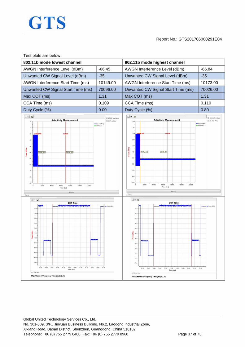
Global United Technology Services Co., Ltd. No. 301-309, 3/F., Jinyuan Business Building, No.2, Laodong Industrial Zone, Xixiang Road, Baoan District, Shenzhen, Guangdong, China 518102 Telephone: +86 (0) 755 2779 8480 Fax: +86 (0) 755 2779 8960 Page 37 of 73
Test plots are below: 802.11b mode lowest channel 802.11b mode highest channel AWGN Interference Level (dBm) -66.45 AWGN Interference Level (dBm) -66.84 Unwanted CW Signal Level (dBm) -35 Unwanted CW Signal Level (dBm) -35 AWGN Interference Start Time (ms) 10149.00 AWGN Interference Start Time (ms) 10173.00 Unwanted CW Signal Start Time (ms) 70096.00 Unwanted CW Signal Start Time (ms) 70026.00 Max COT (ms) 1.31 Max COT (ms) 1.31 CCA Time (ms) 0.109 CCA Time (ms) 0.110 Duty Cycle (%) 0.00 Duty Cycle (%) 0.80

Report No.: GTS201706000291E04
Global United Technology Services Co., Ltd. No. 301-309, 3/F., Jinyuan Business Building, No.2, Laodong Industrial Zone, Xixiang Road, Baoan District, Shenzhen, Guangdong, China 518102 Telephone: +86 (0) 755 2779 8480 Fax: +86 (0) 755 2779 8960 Page 38 of 73

Report No.: GTS201706000291E04
Global United Technology Services Co., Ltd. No. 301-309, 3/F., Jinyuan Business Building, No.2, Laodong Industrial Zone, Xixiang Road, Baoan District, Shenzhen, Guangdong, China 518102 Telephone: +86 (0) 755 2779 8480 Fax: +86 (0) 755 2779 8960 Page 39 of 73
802.11g mode lowest channel 802.11g mode highest channel AWGN Interference Level (dBm) -64.19 AWGN Interference Level (dBm) -64.36 Unwanted CW Signal Level (dBm) -35 Unwanted CW Signal Level (dBm) -35 AWGN Interference Start Time (ms) 10182.00 AWGN Interference Start Time (ms) 10192.00 Unwanted CW Signal Start Time (ms) 70034.00 Unwanted CW Signal Start Time (ms) 70045.00 Max COT (ms) 1.14 Max COT (ms) 2.50 CCA Time (ms) 0.128 CCA Time (ms) 0.128 Duty Cycle (%) 2.59 Duty Cycle (%) 2.00

Report No.: GTS201706000291E04
Global United Technology Services Co., Ltd. No. 301-309, 3/F., Jinyuan Business Building, No.2, Laodong Industrial Zone, Xixiang Road, Baoan District, Shenzhen, Guangdong, China 518102 Telephone: +86 (0) 755 2779 8480 Fax: +86 (0) 755 2779 8960 Page 40 of 73

Report No.: GTS201706000291E04
Global United Technology Services Co., Ltd. No. 301-309, 3/F., Jinyuan Business Building, No.2, Laodong Industrial Zone, Xixiang Road, Baoan District, Shenzhen, Guangdong, China 518102 Telephone: +86 (0) 755 2779 8480 Fax: +86 (0) 755 2779 8960 Page 41 of 73
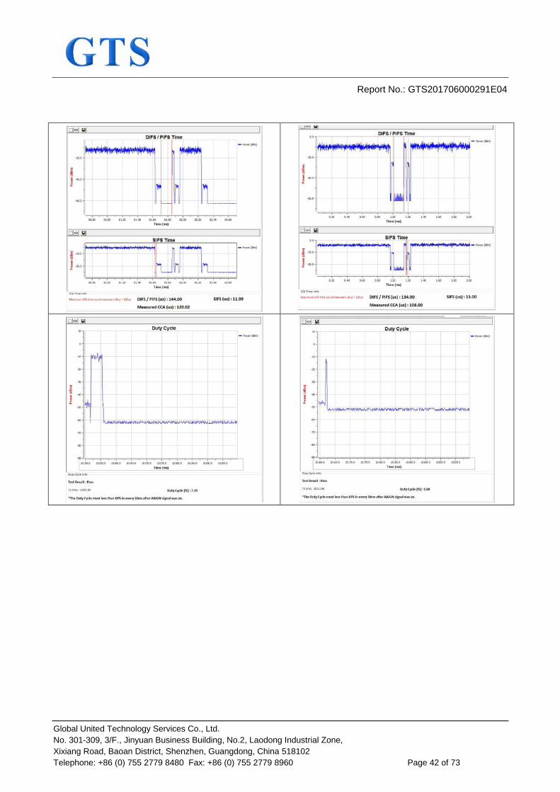
802.11n(HT20) mode lowest channel 802.11n(HT20) mode highest channel AWGN Interference Level (dBm) -64.15 AWGN Interference Level (dBm) -64.31 Unwanted CW Signal Level (dBm) -35 Unwanted CW Signal Level (dBm) -35 AWGN Interference Start Time (ms) 10073.00 AWGN Interference Start Time (ms) 10212.00 Unwanted CW Signal Start Time (ms) 80018.00 Unwanted CW Signal Start Time (ms) 70062.00 Max COT (ms) 2.50 Max COT (ms) 2.50 CCA Time (ms) 0.120 CCA Time (ms) 0.108 Duty Cycle (%) 7.39 Duty Cycle (%) 1.00
Report No.: GTS201706000291E04
Global United Technology Services Co., Ltd. No. 301-309, 3/F., Jinyuan Business Building, No.2, Laodong Industrial Zone, Xixiang Road, Baoan District, Shenzhen, Guangdong, China 518102 Telephone: +86 (0) 755 2779 8480 Fax: +86 (0) 755 2779 8960 Page 42 of 73

Report No.: GTS201706000291E04
Global United Technology Services Co., Ltd. No. 301-309, 3/F., Jinyuan Business Building, No.2, Laodong Industrial Zone, Xixiang Road, Baoan District, Shenzhen, Guangdong, China 518102 Telephone: +86 (0) 755 2779 8480 Fax: +86 (0) 755 2779 8960 Page 43 of 73
802.11n(HT40) mode lowest channel 802.11n(HT40) mode highest channel AWGN Interference Level (dBm) -63.11 AWGN Interference Level (dBm) -63.42 Unwanted CW Signal Level (dBm) -35 Unwanted CW Signal Level (dBm) -35 AWGN Interference Start Time (ms) 10223.00 AWGN Interference Start Time (ms) 10232.00 Unwanted CW Signal Start Time (ms) 70077.00 Unwanted CW Signal Start Time (ms) 70085.00 Max COT (ms) 1.82 Max COT (ms) 2.73 CCA Time (ms) 0.125 CCA Time (ms) 0.117 Duty Cycle (%) 5.59 Duty Cycle (%) 5.59

Report No.: GTS201706000291E04
Global United Technology Services Co., Ltd. No. 301-309, 3/F., Jinyuan Business Building, No.2, Laodong Industrial Zone, Xixiang Road, Baoan District, Shenzhen, Guangdong, China 518102 Telephone: +86 (0) 755 2779 8480 Fax: +86 (0) 755 2779 8960 Page 44 of 73
Note:
During the test, the signal observed on the channel being investigated is the Short Control Signalling
Transmissions.

Report No.: GTS201706000291E04
Global United Technology Services Co., Ltd. No. 301-309, 3/F., Jinyuan Business Building, No.2, Laodong Industrial Zone, Xixiang Road, Baoan District, Shenzhen, Guangdong, China 518102 Telephone: +86 (0) 755 2779 8480 Fax: +86 (0) 755 2779 8960 Page 45 of 73
7.2.4 Occupied Channel Bandwidth
Test Requirement: ETSI EN 300 328 clause 4.3.2.7 Limit: The Occupied Channel Bandwidth for each hopping frequency shall fall
completely within the band 2400MHz ~ 2483.5MHz. In addition, for non-adaptive equipment using wide band modulations other than FHSS and with e.i.r.p. greater than10 dBm, the occupied channel bandwidth shall be less than 20 MHz.
Test setup:
Test Precedure: Step 1: Connect the UUT to the spectrum analyser and use the following settings:
Centre Frequency: The centre frequency of the channel under test
Resolution BW: ~ 1 % of the span without going below 1 % Video BW: 3 × RBW Frequency Span 2 × Nominal Channel Bandwidth Detector Mode: RMS Trace mode: Sweep time:
Max Hold 1 s
Step 2: Wait for the trace to stabilize. Find the peak value of the trace and place the analyser marker on this peak. Step 3: Use the 99 % bandwidth function of the spectrum analyser to measure the Occupied Channel Bandwidth of the UUT. This value shall be recorded. Make sure that the power envelope is sufficiently above the noise floor of the analyser to avoid the noise signals left and right from the power envelope being taken into account by this measurement.
Test Instruments: See section 6.0 Test mode: Transmitting mode

Report No.: GTS201706000291E04
Global United Technology Services Co., Ltd. No. 301-309, 3/F., Jinyuan Business Building, No.2, Laodong Industrial Zone, Xixiang Road, Baoan District, Shenzhen, Guangdong, China 518102 Telephone: +86 (0) 755 2779 8480 Fax: +86 (0) 755 2779 8960 Page 46 of 73
Measurement Data: Remark: Each antenna was tested, and the data of ANT1 is worst. So only the data of ANT1 is reported.
802.11b
Test Channel
99% Bandwidth (MHz)
Declared Bandwidth
(MHz) FL/FH (MHz) Limit Result
Lowest 15.183 20 2404.42 2400MHz ~ 2483.5MHz
Pass Highest 15.177 20 2479.60 Pass
802.11g
Test Channel
99% Bandwidth (MHz)
Declared Bandwidth
(MHz) FL/FH (MHz) Limit Result
Lowest 16.493 20 2403.65 2400MHz ~ 2483.5MHz
Pass Highest 16.693 20 2480.32 Pass
802.11n(H20)
Test Channel
99% Bandwidth (MHz)
Declared Bandwidth
(MHz) FL/FH (MHz) Limit Result
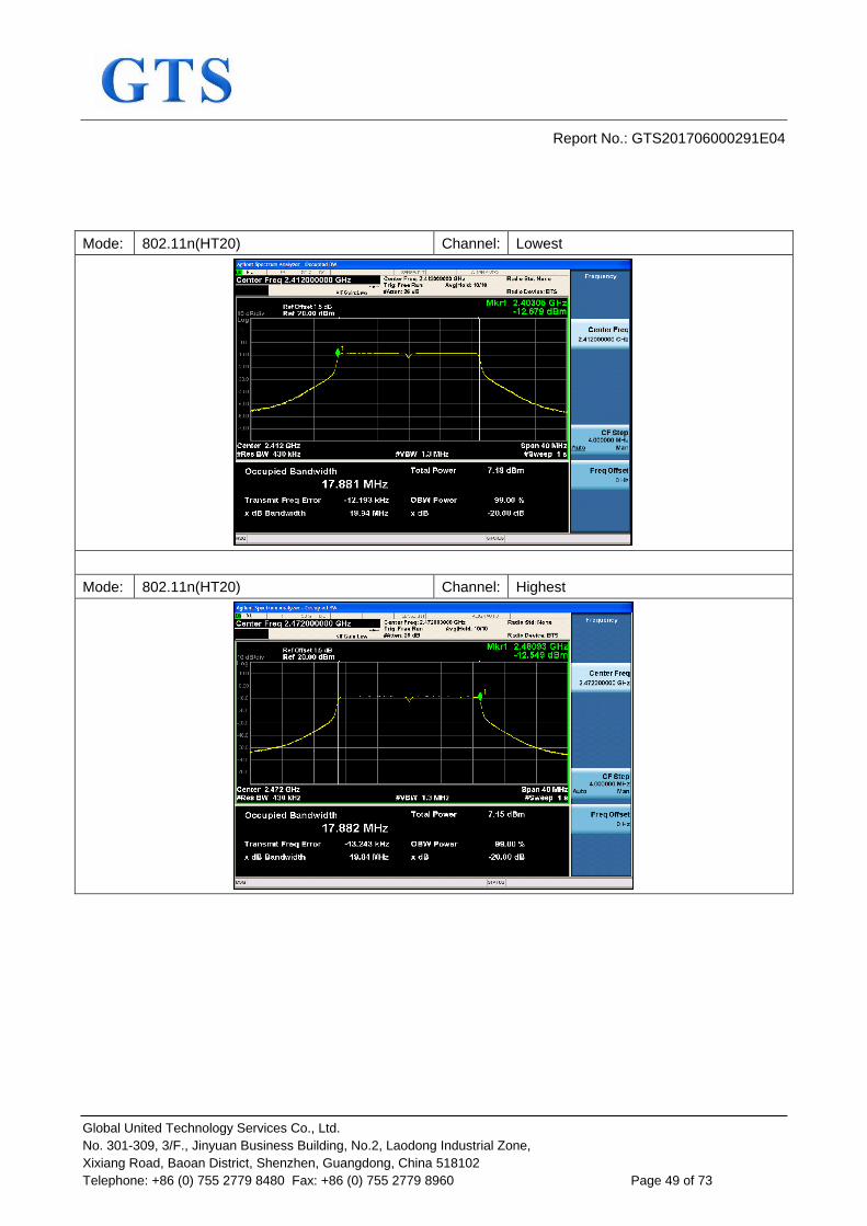
Lowest 17.881 20 2403.05 2400MHz ~ 2483.5MHz
Pass Highest 17.882 20 2480.93 Pass
802.11n(H40)
Test Channel
99% Bandwidth (MHz)
Declared Bandwidth
(MHz) FL/FH (MHz) Limit Result
Lowest 36.257 40 2403.90 2400MHz ~ 2483.5MHz
Pass Highest 36.234 40 2480.10 Pass
Test plots are followed:

Report No.: GTS201706000291E04
Global United Technology Services Co., Ltd. No. 301-309, 3/F., Jinyuan Business Building, No.2, Laodong Industrial Zone, Xixiang Road, Baoan District, Shenzhen, Guangdong, China 518102 Telephone: +86 (0) 755 2779 8480 Fax: +86 (0) 755 2779 8960 Page 47 of 73
Mode: 802.11b Channel: Lowest
Mode: 802.11b Channel: Highest

Report No.: GTS201706000291E04
Global United Technology Services Co., Ltd. No. 301-309, 3/F., Jinyuan Business Building, No.2, Laodong Industrial Zone, Xixiang Road, Baoan District, Shenzhen, Guangdong, China 518102 Telephone: +86 (0) 755 2779 8480 Fax: +86 (0) 755 2779 8960 Page 48 of 73
Mode: 802.11g Channel: Lowest
Mode: 802.11g Channel: Highest
Report No.: GTS201706000291E04
Global United Technology Services Co., Ltd. No. 301-309, 3/F., Jinyuan Business Building, No.2, Laodong Industrial Zone, Xixiang Road, Baoan District, Shenzhen, Guangdong, China 518102 Telephone: +86 (0) 755 2779 8480 Fax: +86 (0) 755 2779 8960 Page 49 of 73
Mode: 802.11n(HT20) Channel: Lowest
Mode: 802.11n(HT20) Channel: Highest

Report No.: GTS201706000291E04
Global United Technology Services Co., Ltd. No. 301-309, 3/F., Jinyuan Business Building, No.2, Laodong Industrial Zone, Xixiang Road, Baoan District, Shenzhen, Guangdong, China 518102 Telephone: +86 (0) 755 2779 8480 Fax: +86 (0) 755 2779 8960 Page 50 of 73
Mode: 802.11n(HT40) Channel: Lowest
Mode: 802.11n(HT40) Channel: Highest

Report No.: GTS201706000291E04
Global United Technology Services Co., Ltd. No. 301-309, 3/F., Jinyuan Business Building, No.2, Laodong Industrial Zone, Xixiang Road, Baoan District, Shenzhen, Guangdong, China 518102 Telephone: +86 (0) 755 2779 8480 Fax: +86 (0) 755 2779 8960 Page 51 of 73
7.2.5 Transmitter unwanted emissions in the OOB domain
Test Requirement: ETSI EN 300 328 clause 4.3.2.8 Test Method: ETSI EN 300 328 clause 5.4.8.2 Limit: The transmitter unwanted emissions in the out-of-band domain but
outside the allocated band, shall not exceed the values provided by the mask in figure 1 Within the band specified in table 1, the Out-of-band emissions are fulfilled by compliance with the Occupied Channel Bandwidth requirement in clause 4.3.1.8.
Test setup:
Test procedure: The applicable mask is defined by the measurement results from the tests performed under clause 5.4.7 (Occupied Channel Bandwidth). The Out-of-band emissions within the different horizontal segments of the mask provided in figures 1 and 3 shall be measured using the step 1 to step 6 below. This method assumes the spectrum analyser is equipped with the Time Domain Power option. Step 1: Connect the UUT to the spectrum analyser and use the following settings:
Centre Frequency: 2 484 MHz Span: 0Hz Resolution BW: 1 MHz Filter mode: Channel filter Video BW: 3 MHz Detector Mode: RMS Trace Mode: Max Hold Sweep Mode: Continuous Sweep Points: Sweep Time [s] / (1 μs) or 5 000 whichever is
greater
Report No.: GTS201706000291E04
Global United Technology Services Co., Ltd. No. 301-309, 3/F., Jinyuan Business Building, No.2, Laodong Industrial Zone, Xixiang Road, Baoan District, Shenzhen, Guangdong, China 518102 Telephone: +86 (0) 755 2779 8480 Fax: +86 (0) 755 2779 8960 Page 52 of 73
Trigger Mode: Video trigger NOTE 1: In case video triggering is not possible, an external trigger source may be used. Sweep Time: >120 % of the duration of the longest burst
detected during the measurement of the RF Output Power
Step 2: (segment 2 483,5 MHz to 2 483,5 MHz + BW) Adjust the trigger level to select the transmissions with the highest power level. For frequency hopping equipment operating in a normal hopping mode, the different hops will result in signal bursts with different power levels. In this case the burst with the highest power level shall be selected. Set a window (start and stop lines) to match with the start and end of the burst and in which the RMS power shall be measured using the Time Domain Power function. Select RMS power to be measured within the selected window and note the result which is the RMS power within this 1 MHz segment (2 483,5 MHz to 2 484,5 MHz). Compare this value with the applicable limit provided by the mask. Increase the centre frequency in steps of 1 MHz and repeat this measurement for every 1 MHz segment within the range 2 483,5 MHz to 2 483,5 MHz + BW. The centre frequency of the last 1 MHz segment shall be set to 2 483,5 MHz + BW - 0,5 MHz (which means this may partly overlap with the previous 1 MHz segment). Step 3: (segment 2 483,5 MHz + BW to 2 483,5 MHz + 2BW) Change the centre frequency of the analyser to 2 484 MHz + BW and perform the measurement for the first 1 MHz segment within range 2 483,5 MHz + BW to 2 483,5 MHz + 2BW. Increase the centre frequency in 1 MHz steps and repeat the measurements to cover this whole range. The centre frequency of the last 1 MHz segment shall be set to 2 483,5 MHz + 2 BW - 0,5 MHz. (which means this may partly overlap with the previous 1 MHz segment). Step 4: (segment 2 400 MHz - BW to 2 400 MHz) Change the centre frequency of the analyser to 2 399,5 MHz and perform the measurement for the first 1 MHz segment within range 2 400 MHz - BW to 2 400 MHz Reduce the centre frequency in 1 MHz steps and repeat the measurements to cover this whole range. The centre frequency of the last 1 MHz segment shall be set to 2 400 MHz - BW + 0,5 MHz (which means this may partly overlap with the previous 1 MHz segment). Step 5: (segment 2 400 MHz - 2BW to 2 400 MHz - BW) Change the centre frequency of the analyser to 2 399,5 MHz - BW and perform the measurement for the first 1 MHz segment within range 2 400 MHz - 2BW to 2 400 MHz - BW. Reduce the centre frequency in 1 MHz steps and repeat the measurements to cover this whole range. The centre frequency of the last 1 MHz segment shall be set to 2 400 MHz - 2BW + 0,5 MHz. (which means this may partly overlap with the previous 1 MHz segment). Step 6:

Report No.: GTS201706000291E04
Global United Technology Services Co., Ltd. No. 301-309, 3/F., Jinyuan Business Building, No.2, Laodong Industrial Zone, Xixiang Road, Baoan District, Shenzhen, Guangdong, China 518102 Telephone: +86 (0) 755 2779 8480 Fax: +86 (0) 755 2779 8960 Page 53 of 73
In case of conducted measurements on equipment with a single transmit chain, the declared antenna assembly gain "G" in dBi shall be added to the results for each of the 1 MHz segments and compared with the limits provided by the mask given in figures 1 or figure 3. If more than one antenna assembly is intended for this power setting, the antenna with the highest gain shall be considered. In case of conducted measurements on smart antenna systems (equipment with multiple transmit chains), the measurements need to be repeated for each of the active transmit chains. The declared antenna assembly gain "G" in dBi for a single antenna shall be added to these results. If more than one antenna assembly is intended for this power setting, the antenna with the highest gain shall be considered. Comparison with the applicable limits shall be done using any of the options given below: Option 1: the results for each of the transmit chains for the corresponding 1 MHz segments shall be added. The additional beamforming gain "Y" in dB shall be added as well and the resulting values compared with the limits provided by the mask given in figure 1 or figure 3. Option 2: the limits provided by the mask given in figure 1 or figure 3 shall be reduced by 10 x log10(Ach) and the additional beamforming gain "Y" in dB. The results for each of the transmit chains shall be individually compared with these reduced limits. NOTE: Ach refers to the number of active transmit chains. It shall be recorded whether the equipment complies with the mask provided in figure 1 or figure 3.
Measurement Record: Uncertainty: ± 1.5dB Test Instruments: See section 6.0 Test mode: Transmitting mode

Report No.: GTS201706000291E04
Global United Technology Services Co., Ltd. No. 301-309, 3/F., Jinyuan Business Building, No.2, Laodong Industrial Zone, Xixiang Road, Baoan District, Shenzhen, Guangdong, China 518102 Telephone: +86 (0) 755 2779 8480 Fax: +86 (0) 755 2779 8960 Page 54 of 73
Measurement Data: Test plots at normal condition are followed: Test Condition: Normal condition Mode: 802.11b Channel: Lowest Mode: 802.11b Channel: Highest
Mode: 802.11g Channel: Lowest Mode: 802.11g Channel: Highest
Mode: 802.11n(HT20) Channel: Lowest Mode: 802.11n(HT20) Channel: Highest
Mode: 802.11n(HT40) Channel: Lowest Mode: 802.11n(HT40) Channel: Highest

Report No.: GTS201706000291E04
Global United Technology Services Co., Ltd. No. 301-309, 3/F., Jinyuan Business Building, No.2, Laodong Industrial Zone, Xixiang Road, Baoan District, Shenzhen, Guangdong, China 518102 Telephone: +86 (0) 755 2779 8480 Fax: +86 (0) 755 2779 8960 Page 55 of 73
7.2.6 Transmitter unwanted emissions in the spurious domain
Test Requirement: ETSI EN 300 328 clause 4.3.2.9 Test Method: ETSI EN 300 328 clause 5.4.9.2 Limit:
Frequency Range Maximum power e.r.p. (≤ 1 GHz) e.i.r.p. (> 1 GHz)
Bandwidth
30 MHz to 47 MHz -36 dBm 100 kHz 47 MHz to 74 MHz -54 dBm 100 kHz
74 MHz to 87.5 MHz -36 dBm 100 kHz 87.5 MHz to 118 MHz -54 dBm 100 kHz 118 MHz to 174 MHz -36 dBm 100 kHz 174 MHz to 230 MHz -54 dBm 100 kHz 230 MHz to 470 MHz -36 dBm 100 kHz 470 MHz to 862 MHz -54 dBm 100 kHz
862 MHz to 1 GHz -36 dBm 100 kHz 1 GHz to 12.75 GHz -30 dBm 1 MHz
Test Frequency range: 30MHz to 12.75GHz Test setup: Below 1GHz
Above 1GHz

Report No.: GTS201706000291E04
Global United Technology Services Co., Ltd. No. 301-309, 3/F., Jinyuan Business Building, No.2, Laodong Industrial Zone, Xixiang Road, Baoan District, Shenzhen, Guangdong, China 518102 Telephone: +86 (0) 755 2779 8480 Fax: +86 (0) 755 2779 8960 Page 56 of 73
Test procedure: 1. Pre-scan
The test procedure below shall be used to identify potential unwanted emissions of the UUT. Step 1: The sensitivity of the measurement set-up should be such that the noise floor is at least 12 dB below the limits given in table 4 or table 12. Step 2: The emissions over the range 30 MHz to 1 000 MHz shall be identified. Spectrum analyser settings:
Resolution BW: 100 kHz Video BW Filter type:
300 kHz 3 dB (Gaussian)
Detector mode: Peak Trace Mode: Max Hold Sweep Points: ≥19 400
For spectrum analysers not supporting this high number of sweep points, the frequency band may need to be segmented. Sweep time: For non continuous transmissions (duty cycle
less than 100 %), the sweep time shall be sufficiently long, such that for each 100 kHz frequency step, the measurement time is greater than two transmissions of the UUT.on any channel For Frequency Hopping equipment operating in a normal operating (hopping not disabled) mode, the sweep time shall be further increased to capture multiple transmissions on the same hopping frequency in different hopping sequences.
The above sweep time setting may result in long measuring times in case of frequency hopping equipment. To avoid such long measuring times, an FFT analyser could be used.
Allow the trace to stabilize. Any emissions identified during the sweeps above and that fall within the 6 dB range below the applicable limit or above, shall be individually measured using the procedure in clause

Report No.: GTS201706000291E04
Global United Technology Services Co., Ltd. No. 301-309, 3/F., Jinyuan Business Building, No.2, Laodong Industrial Zone, Xixiang Road, Baoan District, Shenzhen, Guangdong, China 518102 Telephone: +86 (0) 755 2779 8480 Fax: +86 (0) 755 2779 8960 Page 57 of 73
5.4.9.2.1.3 and compared to the limits given in table 4 or table 12. Step 3: The emissions over the range 1 GHz to 12,75 GHz shall be identified. Spectrum analyser settings:
Resolution BW: 1 MHz Video BW Filter type:
3 MHz 3 dB (Gaussian)
Detector mode: Peak Trace Mode: Max Hold Sweep Points: ≥ 23 500 For spectrum analysers not supporting this high number of sweep points, the frequency band may need to be segmented. Sweep time: For non continuous transmissions (duty cycle
less than 100 %), the sweep time shall be sufficiently long, such that for each 1 MHz frequency step, the measurement time is greater than two transmissions of the UUT.on any channel For Frequency Hopping equipment operating in a normal operating (hopping not disabled) mode, the sweep time shall be further increased to capture multiple transmissions on the same hopping frequencies
The above sweep time setting may result in long measuring times in case of frequency hopping equipment. To avoid such long measuring times, an FFT analyser could be used.
Allow the trace to stabilize. Any emissions identified during the sweeps above that fall within the 6 dB range below the applicable limit or above, shall be individually measured using the procedure in clause 5.4.9.2.1.3 and compared to the limits given in table 4 or table 12. Frequency Hopping equipment may generate a block (or several blocks) of spurious emissions anywhere within the spurious domain. If this is the case, only the highest peak of each block of emissions shall be measured using the procedure in clause 5.4.9.2.1.3. Step 4: In case of conducted measurements on smart antenna systems (equipment with multiple transmit chains), the steps 2 and 3 need to be repeated for each of the active transmit chains (Ach).The limits used to identify emissions during this pre-scan need to be reduced by 10 × log10 (Ach) 2. Measurement of the emissions identified during the pre-scan The procedure in step 1 to step 4 below shall be used to accurately measure the individual unwanted emissions identified during the pre-scan measurements above. This method assumes the spectrum analyser has a Time Domain Power function. Step 1: The level of the emissions shall be measured using the following spectrum analyser settings:

Report No.: GTS201706000291E04
Global United Technology Services Co., Ltd. No. 301-309, 3/F., Jinyuan Business Building, No.2, Laodong Industrial Zone, Xixiang Road, Baoan District, Shenzhen, Guangdong, China 518102 Telephone: +86 (0) 755 2779 8480 Fax: +86 (0) 755 2779 8960 Page 58 of 73
Measurement Mode: Centre Frequency:
Time Domain Power Frequency of emission identified during the pre-scan
Resolution BW: 100 kHz (< 1 GHz) / 1 MHz (> 1 GHz) Video BW 300 kHz (< 1 GHz) / 3 MHz (> 1 GHz) Frequency Span: Zero Span Sweep mode: Single Sweep Sweep time: Sweep points:
> 120 % of the duration of the longest burst detected during the measurement of the RF Output Power Sweep time [μs] / (1 μs) with a maximum of 30 000
Trigger: Video (burst signals) or Manual (continuous signals)
Detector: RMS
Step 2: Set a window where the start and stop indicators match the start and end of the burst with the highest level and record the value of the power measured within this window.If the spurious emission to be measured is a continuous transmission, the measurement window shall be set to match the start and stop times of the sweep. Step 3: In case of conducted measurements on smart antenna systems (equipment with multiple transmit chains), step 2 needs to be repeated for each of the active transmit chains (Ach). Sum the measured power (within the observed window) for each of the active transmit chains. Step 4: The value defined in step 3 shall be compared to the limits defined in table 4 or table 12.
Measurement Record: Uncertainty: ± 6dB Test Instruments: See section 6.0 Test mode: Transmitting mode

Report No.: GTS201706000291E04
Global United Technology Services Co., Ltd. No. 301-309, 3/F., Jinyuan Business Building, No.2, Laodong Industrial Zone, Xixiang Road, Baoan District, Shenzhen, Guangdong, China 518102 Telephone: +86 (0) 755 2779 8480 Fax: +86 (0) 755 2779 8960 Page 59 of 73
Measurement Data Remark: Each antenna was tested, and the data of ANT1 is worst. So only the data of ANT1 is reported.
802.11b mode The lowest channel
Frequency (MHz) Spurious Emission
Limit (dBm) Test Result polarization Level(dBm)
96.68 Vertical -69.83 -54.00
Pass
497.02 V -66.28 -54.00 4824.00 V -42.07 -30.00 7236.00 V -44.71 -30.00 9648.00 V -41.26 -30.00 12060.00 V -42.39 -30.00
179.29 Horizontal -68.59 -54.00 681.16 H -64.17 -54.00
4824.00 H -44.36 -30.00 7236.00 H -44.84 -30.00 9648.00 H -41.69 -30.00 12060.00 H -43.65 -30.00
The highest channel
Frequency (MHz) Spurious Emission
Limit (dBm) Test Result polarization Level(dBm)
144.50 Vertical -71.27 -36.00
Pass
644.10 V -62.60 -54.00 4944.00 V -42.58 -30.00 7416.00 V -44.18 -30.00 9888.00 V -42.94 -30.00 12360.00 V -42.51 -30.00
256.75 Horizontal -68.65 -36.00 845.22 H -61.66 -54.00
4944.00 H -43.72 -30.00 7416.00 H -44.62 -30.00 9888.00 H -42.86 -30.00 12360.00 H -43.10 -30.00

Report No.: GTS201706000291E04
Global United Technology Services Co., Ltd. No. 301-309, 3/F., Jinyuan Business Building, No.2, Laodong Industrial Zone, Xixiang Road, Baoan District, Shenzhen, Guangdong, China 518102 Telephone: +86 (0) 755 2779 8480 Fax: +86 (0) 755 2779 8960 Page 60 of 73
802.11g mode
The lowest channel
Frequency (MHz) Spurious Emission
Limit (dBm) Test Result polarization Level(dBm)
102.37 Vertical -70.76 -54.00
Pass
414.67 V -67.49 -36.00 4824.00 V -51.55 -30.00 7236.00 V -44.94 -30.00 9648.00 V -41.69 -30.00 12060.00 V -43.97 -30.00
129.22 Horizontal -68.76 -36.00 739.11 H -68.09 -54.00
4824.00 H -50.59 -30.00 7236.00 H -44.38 -30.00 9648.00 H -42.03 -30.00 12060.00 H -44.69 -30.00
The highest channel
Frequency (MHz) Spurious Emission
Limit (dBm) Test Result polarization Level(dBm)
157.95 Vertical -69.90 -36.00
Pass
998.90 V -62.45 -36.00 4944.00 V -51.27 -30.00 7416.00 V -44.30 -30.00 9888.00 V -42.29 -30.00 12360.00 V -42.49 -30.00
127.09 Horizontal -69.15 -36.00 804.13 H -71.00 -54.00
4944.00 H -50.51 -30.00 7416.00 H -44.81 -30.00 9888.00 H -41.58 -30.00 12360.00 H -41.35 -30.00

Report No.: GTS201706000291E04
Global United Technology Services Co., Ltd. No. 301-309, 3/F., Jinyuan Business Building, No.2, Laodong Industrial Zone, Xixiang Road, Baoan District, Shenzhen, Guangdong, China 518102 Telephone: +86 (0) 755 2779 8480 Fax: +86 (0) 755 2779 8960 Page 61 of 73
802.11n(HT20) mode The lowest channel
Frequency (MHz) Spurious Emission
Limit (dBm) Test Result polarization Level(dBm)
198.38 Vertical -69.17 -54.00
Pass
812.47 V -63.65 -54.00 4824.00 V -51.95 -30.00 7236.00 V -44.52 -30.00 9648.00 V -42.79 -30.00 12060.00 V -42.80 -30.00
206.92 Horizontal -69.39 -54.00 753.01 H -61.65 -54.00
4824.00 H -51.90 -30.00 7236.00 H -45.45 -30.00 9648.00 H -42.91 -30.00 12060.00 H -44.29 -30.00
The highest channel
Frequency (MHz) Spurious Emission
Limit (dBm) Test Result polarization Level(dBm)
287.95 Vertical -68.54 -36.00
Pass
940.66 V -65.36 -36.00 4944.00 V -51.46 -30.00 7416.00 V -43.54 -30.00 9888.00 V -42.39 -30.00 12360.00 V -43.40 -30.00
146.95 Horizontal -71.37 -36.00 911.79 H -70.78 -36.00
4944.00 H -50.12 -30.00 7416.00 H -45.97 -30.00 9888.00 H -42.60 -30.00 12360.00 H -44.83 -30.00

Report No.: GTS201706000291E04
Global United Technology Services Co., Ltd. No. 301-309, 3/F., Jinyuan Business Building, No.2, Laodong Industrial Zone, Xixiang Road, Baoan District, Shenzhen, Guangdong, China 518102 Telephone: +86 (0) 755 2779 8480 Fax: +86 (0) 755 2779 8960 Page 62 of 73
802.11n(HT40) mode The lowest channel
Frequency (MHz) Spurious Emission
Limit (dBm) Test Result polarization Level(dBm)
118.96 Vertical -68.95 -36.00
Pass
518.84 V -59.81 -54.00 4824.00 V -51.74 -30.00 7236.00 V -44.79 -30.00 9648.00 V -42.21 -30.00 12110.00 V -44.43 -30.00
156.66 Horizontal -67.82 -36.00 737.55 H -62.85 -54.00
4824.00 H -51.44 -30.00 7236.00 H -44.94 -30.00 9648.00 H -41.66 -30.00 12110.00 H -44.26 -30.00
The highest channel
Frequency (MHz) Spurious Emission
Limit (dBm) Test Result polarization Level(dBm)
121.08 Vertical -68.65 -36.00
Pass
886.15 V -61.78 -36.00 4944.00 V -51.53 -30.00 7416.00 V -45.11 -30.00 9888.00 V -41.55 -30.00 12310.00 V -44.27 -30.00
197.57 Horizontal -66.35 -54.00 638.27 H -63.51 -54.00
4944.00 H -49.64 -30.00 7416.00 H -45.50 -30.00 9888.00 H -43.52 -30.00 12310.00 H -45.37 -30.00

Report No.: GTS201706000291E04
Global United Technology Services Co., Ltd. No. 301-309, 3/F., Jinyuan Business Building, No.2, Laodong Industrial Zone, Xixiang Road, Baoan District, Shenzhen, Guangdong, China 518102 Telephone: +86 (0) 755 2779 8480 Fax: +86 (0) 755 2779 8960 Page 63 of 73
7.3 Receiver Requirement 7.3.1 Spurious Emissions
Test Requirement: ETSI EN 300 328 clause 4.3.2.10 Test Method: ETSI EN 300 328 clause 5.4.10.2 Limit:
Frequency Maximum power e.r.p. (≤ 1 GHz) e.i.r.p. (> 1 GHz)
Measurement bandwidth
30MHz to 1000 MHz -57 dBm 100 kHz 1GHz to 12.75GHz -47 dBm 1 MHz
Test Frequency range: 30MHz to 12.75GHz Test setup: Below 1GHz
Above 1GHz

Report No.: GTS201706000291E04
Global United Technology Services Co., Ltd. No. 301-309, 3/F., Jinyuan Business Building, No.2, Laodong Industrial Zone, Xixiang Road, Baoan District, Shenzhen, Guangdong, China 518102 Telephone: +86 (0) 755 2779 8480 Fax: +86 (0) 755 2779 8960 Page 64 of 73
Test procedure: 1. Pre-scan
The procedure in step 1 to step 4 below shall be used to identify potential unwanted emissions of the UUT. Step 1: The sensitivity of the spectrum analyser should be such that the noise floor is at least 12 dB below the limits given in tables 5 or table13. Step 2: The emissions over the range 30 MHz to 1 000 MHz shall be identified. Spectrum analyser settings:
Resolution BW: 100 kHz Video BW Filter type:
300 kHz 3dB (Gaussian)
Detector mode: Peak Trace Mode: Max Hold Sweep Points: ≥ 19 400 Sweep time: Auto
Wait for the trace to stabilize. Any emissions identified during the sweeps above and that fall within the 6 dB range below the applicable limit or above, shall be individually measured using the procedure in clause 5.4.10.2.1.3 and compared to the limits given in table 5 or table 13. Step 3: The emissions over the range 1 GHz to 12,75 GHz shall be identified. Spectrum analyser settings:
Resolution BW: 1 MHz Video BW Filter type:
3 MHz 3 dB (Gaussian)
Detector mode: Peak Trace Mode: Max Hold Sweep Points: ≥ 23500; for spectrum analysers not
supporting this high number of sweep points,the frequency band may be segmented
Sweep time: Auto Wait for the trace to stabilize. Any emissions identified during the sweeps above that fall within the 6 dB range below, the applicable limit or above, shall be individually measured using the procedure in clause 5.4.10.2.1.3 and compared to the limits given in table 5 or table 13. Frequency Hopping equipment may generate a block (or several blocks) of spurious emissions anywhere within the spurious domain. If this is the case, only the highest peak of each block of emissions shall be measured using the procedure in clause 5.4.10.2.1.3. Step 4: In case of conducted measurements on smart antenna systems (equipment with multiple transmit chains), the steps 2 and 3 need to be repeated for each of the active transmit chains (Ach).The limits used to identifyemissions during this pre-scan need to be reduced with 10 × log10 (Ach)

Report No.: GTS201706000291E04
Global United Technology Services Co., Ltd. No. 301-309, 3/F., Jinyuan Business Building, No.2, Laodong Industrial Zone, Xixiang Road, Baoan District, Shenzhen, Guangdong, China 518102 Telephone: +86 (0) 755 2779 8480 Fax: +86 (0) 755 2779 8960 Page 65 of 73
2. Measurement of the emissions identified during the pre-scan The procedure in step 1 to step 4 below shall be used to accurately measure the individual unwanted emissions identified during the pre-scan measurements above. This method assumes the spectrum analyser has a Time Domain Power function. Step 1: The level of the emissions shall be measured using the following spectrum analyser settings: Measurement Mode: Time Domain Power
Centre Frequency: Frequency of the emission identified during the pre-scan
Resolution Bandwidth: 100 kHz (< 1 GHz) / 1 MHz (> 1 GHz)
Video Bandwidth: 300 kHz (< 1 GHz) / 3 MHz (> 1 GHz)
Frequency Span: Zero Span
Sweep mode: Single Sweep Sweep time: 30 ms
Sweep points: ≥ 30 000
Trigger: Video (for burst signals) or Manual (for continuous signals
Detector: RMS Step 2: Set a window where the start and stop indicators match the start and end of the burst with the highest level and record, the value of the power measured within this window. If the spurious emission to be measured is a continuous, transmission, the measurement window shall be set to the start and stop times of the sweep. Step 3: In case of conducted measurements on smart antenna systems (equipment with multiple receive chains), step 2 needs to be repeated for each of the active receive chains Ach.Sum the measured power (within the observed window) for each of the active receive chains. Step 4: The value defined in step 3 shall be compared to the limits defined in table 5 and table 13.
Measurement Record: Uncertainty: ± 6dB Test mode: Kept Rx in receiving mode Test Instruments: See section 6.0
Remark: Both ANT 1 and ANT 2 were tested, and found the case which ANT 1 was the worst case. Only show test data of the worse case on the test report.

Report No.: GTS201706000291E04
Global United Technology Services Co., Ltd. No. 301-309, 3/F., Jinyuan Business Building, No.2, Laodong Industrial Zone, Xixiang Road, Baoan District, Shenzhen, Guangdong, China 518102 Telephone: +86 (0) 755 2779 8480 Fax: +86 (0) 755 2779 8960 Page 66 of 73
Measurement Data:
802.11b mode The lowest channel
Frequency (MHz) Spurious Emission
Limit (dBm) Test Result polarization Level(dBm)
114.60 Vertical -71.28
2nW/ -57dBm below 1GHz,
20nW/ -47dBm above 1GHz.
Pass
802.32 V -65.25 4824.00 V -64.41 7236.00 V -57.61 9648.00 V -54.12 12060.00 V -53.60
227.74 Horizontal -71.01 520.04 H -64.15
4824.00 H -61.34 7236.00 H -58.01 9648.00 H -55.29 12060.00 H -53.81
The highest channel
Frequency (MHz) Spurious Emission
Limit (dBm) Test Result polarization Level(dBm)
96.44 Vertical -71.86
2nW/ -57dBm below 1GHz,
20nW/ -47dBm above 1GHz.
Pass
625.31 V -65.04 4944.00 V -62.65 7416.00 V -57.89 9888.00 V -54.15 12360.00 V -52.70
177.61 Horizontal -69.92 540.70 H -63.50
4944.00 H -61.98 7416.00 H -55.26 9888.00 H -52.22 12360.00 H -51.95

Report No.: GTS201706000291E04
Global United Technology Services Co., Ltd. No. 301-309, 3/F., Jinyuan Business Building, No.2, Laodong Industrial Zone, Xixiang Road, Baoan District, Shenzhen, Guangdong, China 518102 Telephone: +86 (0) 755 2779 8480 Fax: +86 (0) 755 2779 8960 Page 67 of 73
802.11g mode
The lowest channel
Frequency (MHz) Spurious Emission
Limit (dBm) Test Result polarization Level(dBm)
104.19 Vertical -70.31
2nW/ -57dBm below 1GHz,
20nW/ -47dBm above 1GHz.
Pass
658.07 V -66.28 4944.00 V -62.71 7416.00 V -57.81 9888.00 V -53.58 12360.00 V -52.94
120.92 Horizontal -69.93 591.23 H -66.08
4944.00 H -61.48 7416.00 H -55.25 9888.00 H -53.57 12360.00 H -52.35
The highest channel
Frequency (MHz) Spurious Emission
Limit (dBm) Test Result polarization Level(dBm)
141.47 Vertical -71.71
2nW/ -57dBm below 1GHz,
20nW/ -47dBm above 1GHz.
Pass
664.33 V -72.42 4944.00 V -62.03 7416.00 V -57.09 9888.00 V -53.15 12360.00 V -52.59
152.58 Horizontal -71.19 749.14 H -67.47
4944.00 H -61.29 7416.00 H -56.68 9888.00 H -54.11 12360.00 H -51.97
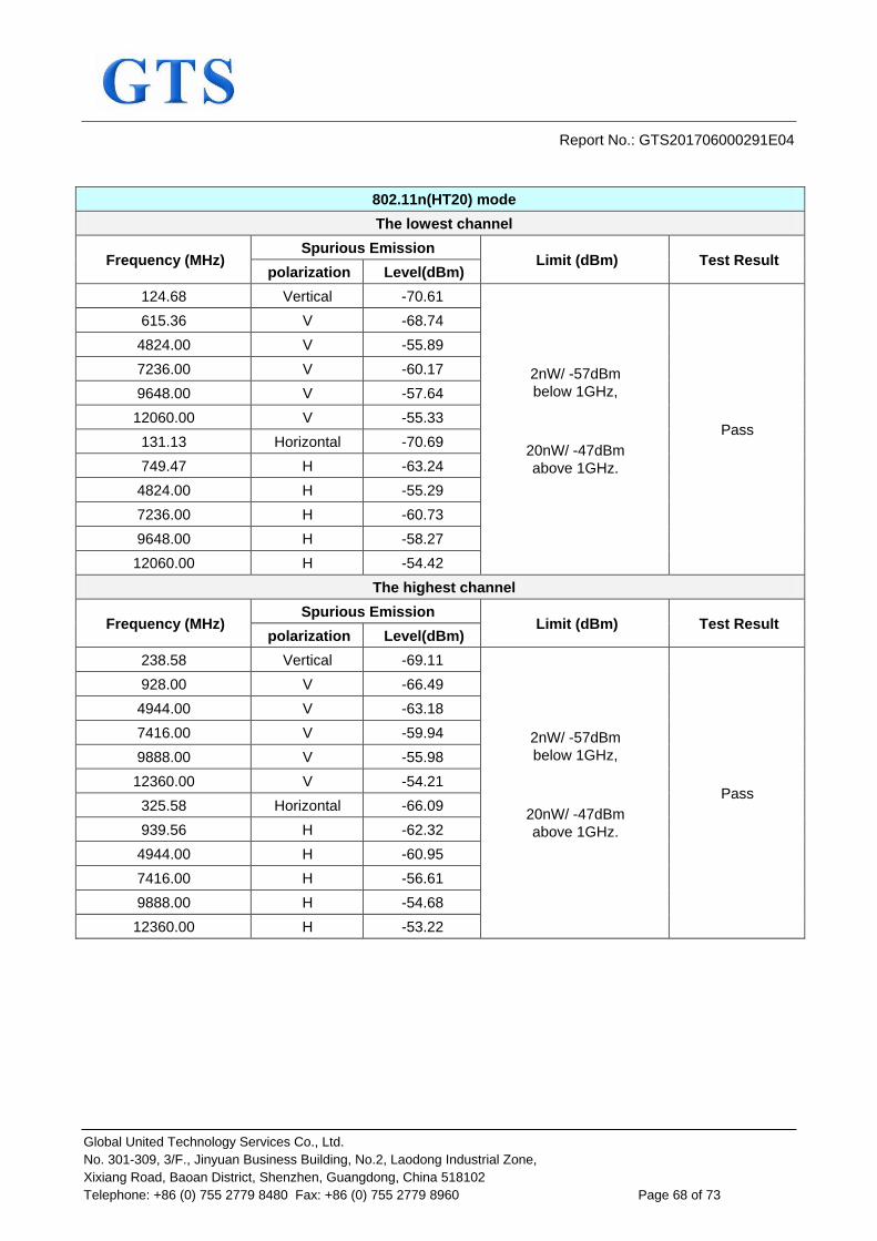
Report No.: GTS201706000291E04
Global United Technology Services Co., Ltd. No. 301-309, 3/F., Jinyuan Business Building, No.2, Laodong Industrial Zone, Xixiang Road, Baoan District, Shenzhen, Guangdong, China 518102 Telephone: +86 (0) 755 2779 8480 Fax: +86 (0) 755 2779 8960 Page 68 of 73
802.11n(HT20) mode The lowest channel
Frequency (MHz) Spurious Emission
Limit (dBm) Test Result polarization Level(dBm)
124.68 Vertical -70.61
2nW/ -57dBm below 1GHz,
20nW/ -47dBm above 1GHz.
Pass
615.36 V -68.74 4824.00 V -55.89 7236.00 V -60.17 9648.00 V -57.64 12060.00 V -55.33
131.13 Horizontal -70.69 749.47 H -63.24
4824.00 H -55.29 7236.00 H -60.73 9648.00 H -58.27 12060.00 H -54.42
The highest channel
Frequency (MHz) Spurious Emission
Limit (dBm) Test Result polarization Level(dBm)
238.58 Vertical -69.11
2nW/ -57dBm below 1GHz,
20nW/ -47dBm above 1GHz.
Pass
928.00 V -66.49 4944.00 V -63.18 7416.00 V -59.94 9888.00 V -55.98 12360.00 V -54.21
325.58 Horizontal -66.09 939.56 H -62.32
4944.00 H -60.95 7416.00 H -56.61 9888.00 H -54.68 12360.00 H -53.22

Report No.: GTS201706000291E04
Global United Technology Services Co., Ltd. No. 301-309, 3/F., Jinyuan Business Building, No.2, Laodong Industrial Zone, Xixiang Road, Baoan District, Shenzhen, Guangdong, China 518102 Telephone: +86 (0) 755 2779 8480 Fax: +86 (0) 755 2779 8960 Page 69 of 73
802.11n(HT40) mode The lowest channel
Frequency (MHz) Spurious Emission
Limit (dBm) Test Result polarization Level(dBm)
122.22 Vertical -68.00
2nW/ -57dBm below 1GHz,
20nW/ -47dBm above 1GHz.
Pass
798.08 V -71.79 4844.00 V -63.17 7266.00 V -56.44 9688.00 V -52.80 12110.00 V -52.99
172.38 Horizontal -67.04 902.96 H -71.09
4844.00 H -61.48 7266.00 H -57.32 9688.00 H -54.77 12110.00 H -52.53
The highest channel
Frequency (MHz) Spurious Emission
Limit (dBm) Test Result polarization Level(dBm)
313.70 Vertical -68.91
2nW/ -57dBm below 1GHz,
20nW/ -47dBm above 1GHz.
Pass
649.53 V -71.39 4924.00 V -62.65 7386.00 V -57.89 9848.00 V -54.15 12310.00 V -53.05
371.63 Horizontal -67.82 657.79 H -71.22
4924.00 H -61.65 7386.00 H -56.36 9848.00 H -54.14 12310.00 H -52.68

Report No.: GTS201706000291E04
Global United Technology Services Co., Ltd. No. 301-309, 3/F., Jinyuan Business Building, No.2, Laodong Industrial Zone, Xixiang Road, Baoan District, Shenzhen, Guangdong, China 518102 Telephone: +86 (0) 755 2779 8480 Fax: +86 (0) 755 2779 8960 Page 70 of 73
7.3.2 Receiver Blocking
Test Requirement: ETSI EN 300 328 clause 4.3.2.11 Test Method: ETSI EN 300 328 clause 5.4.11.2. Limit: While maintaining the minimum performance criteria as defined in clause
4.3.2.11.3, the blocking levels at specified frequency offsets shall be equal to or greater than the limits defined for the applicable receiver category provided in table 14, table 15 or table 16.

Report No.: GTS201706000291E04
Global United Technology Services Co., Ltd. No. 301-309, 3/F., Jinyuan Business Building, No.2, Laodong Industrial Zone, Xixiang Road, Baoan District, Shenzhen, Guangdong, China 518102 Telephone: +86 (0) 755 2779 8480 Fax: +86 (0) 755 2779 8960 Page 71 of 73
Test setup:
Test procedure: For systems using multiple receive chains only one chain (antenna port) need to be tested. All other receiver inputs shall be terminated. The procedure in step 1 to step 6 below shall be used to verify the receiver blocking requirement as described in clause 4.3.1.12 or clause 4.3.2.11. Table 6, table 7 and table 8 in clause 4.3.1.12.4 contain the applicable blocking frequencies and blocking levels for each of the receiver categories for testing Receiver Blocking on frequency hopping equipment. Table 14, table 15 and table 16 in clause 4.3.2.11.4 contain the applicable blocking frequencies and blocking levels for each of the receiver categories for testing Receiver Blocking on equipment using wide band modulations other than FHSS. Step 1: For non-frequency hopping equipment, the UUT shall be set to the lowest operating channel. Step 2: The blocking signal generator is set to the first frequency as defined in the appropriate table corresponding to the receiver category and type of equipment. Step 3: With the blocking signal generator switched off, a communication link is established between the UUT and the associated companion device using the test setup shown in figure 6. The attenuation of the variable attenuator shall be increased in 1 dB steps to a value at which the minimum performance criteria as specified in clause 4.3.1.12.3 or clause 4.3.2.11.3 is still met. The resulting level for the wanted signal at the input of the UUT is Pmin. This signal level (Pmin) is increased by the value provided in the table corresponding to the receiver category and type of equipment. Step 4: The blocking signal at the UUT is set to the level provided in the table corresponding to the receiver category and type of equipment. It shall be verified and recorded in the test report that the performance criteria as specified in clause 4.3.1.12.3 or clause 4.3.2.11.3 is met. Step 5: Repeat step 4 for each remaining combination of frequency and level for the blocking signal as provided in the table corresponding to the receiver category and type of equipment. Step 6: For non-frequency hopping equipment, repeat step 2 to step 5 with the UUT operating at the highest operating channel.

Report No.: GTS201706000291E04
Global United Technology Services Co., Ltd. No. 301-309, 3/F., Jinyuan Business Building, No.2, Laodong Industrial Zone, Xixiang Road, Baoan District, Shenzhen, Guangdong, China 518102 Telephone: +86 (0) 755 2779 8480 Fax: +86 (0) 755 2779 8960 Page 72 of 73
Measurement Record: Uncertainty: N/A Test Instruments: See section 6.0 Test mode: Normal link mode
Measurement Data:
Test Channel Pmin(dBm) PER(%) Limit of
PER(%)
Wanted signal mean power companion (Pmin+6dB)
Blocking signal
frequency (MHz)
Blocking signal Power (dBm)
Type of blocking
signal Result
Lowest Channel -85.90 9.25
10
-79.90 2300.00 -47
CW Pass
-79.90 2330.00 -47 -79.90 2360.00 -47 -79.90 2380.00 -57
Highest Channel -86.40 9.41
-80.40 2503.50 -57 -80.40 2523.50 -47 -80.40 2553.50 -47 -80.40 2583.50 -47 -80.40 2613.50 -47 -80.40 2643.50 -47 -80.40 2673.50 -47
Note: During the blocking test.The value of PER was no changed.Maybe the value of PER has a slight floating,but no bigger than 10%.
Remark: According to ETSI EN 300328 V2.1.1 clause 5.4.11.1. Only the lowest data rate of 802.11b mode
was tested and recorded.

Report No.: GTS201706000291E04
Global United Technology Services Co., Ltd. No. 301-309, 3/F., Jinyuan Business Building, No.2, Laodong Industrial Zone, Xixiang Road, Baoan District, Shenzhen, Guangdong, China 518102 Telephone: +86 (0) 755 2779 8480 Fax: +86 (0) 755 2779 8960 Page 73 of 73
8 Test setup photo
9 EUT Constructional Details Reference to the test report No. : GTS201706000291E01
------end------