Embed Size (px)
Citation preview
AUTOMATIC GENERATION CONTROL RESPONSE TESTS PERFORMED FOR
WESTERN AREA POWER ADMINISTRATION'S UPPER COLORADOILOWER MISSOURI
CONTROL AREA
June 1994
U.S. DEPARTMENT OF THE INTERIOR Bureau of Reclamation
Denver Office Research and Laboratory Services Division
Electric Power Branch
...................................... ........................ j.:sw.:.:.:.:.:.:.:.:.:.:.:I ................................................... 3. RECIPIENT'S CATALOG NO.
.............................. I 5. REPORT DATE
Automatic Generation Control Response Tests Performed for Western Area Power Administration's Upper ColoradolLower Missouri Control Area
7 AUTHOR(S)
S.C. St i t t and R.L. Riney
9. PERFORMING ORGANIZATION NAME AND ADDRESS
Bureau of Reclamation Denver Office Denver CO 80225
12. SPONSORING AGENCY NAME AND ADDRESS
1 Same
J u n e 1994 6. PERFORMING ORGANIZATION CODE
1 10. WORK UNIT NO
11. CONTRACT OR GRANT NO.
13. TYPE OF REPORT AND PERIOD COVERED
14. SPONSORING AGENCY CODE I DlBR 15. SUPPLEMENTARY NOTES
Microfiche and hard copy available at the Denver Office, Denver, Colorado
16. ABSTRACT
A summary of the work performed by Reclamation's Electric Power Branch to test t h ~ automatic generation control response of powerplants within the Western Area Uppel ColoradoLower Missouri combined control area i s given.
17. KEY WORDS AND DOCUMENT ANALYSIS
a. DESCRIPTORS-- automatic generation control/
b. IDENTIFIERS- Glen Canyon Powerplant/ Yellowtail Powerplant
CO WRR:
Available from the National Technical Informat~on Servlce, Operations D~vis~on, 5285 Pan Royal Road, Springfield, Virginia 22161
SRIM: i 19. SECURITY CLASS I 21. NO. OF PAGES
UNCLASSIFIED
1 20. SECURITY CLASS 1 22. PRICE
AUTOMATIC GENERATION CONTROL RESPONSE TESTS PERFORMED FOR
WESTERN AREA POWER ADMINISTRATION'S UPPER COLORADOILOWER MISSOURI
CONTROL AREA
by
S.C. stm and R.L. Riney
Electric Power Branch Research and Laboratory Services Division
Denver Office Denver, Colorado
June 1994
UNITED STATES DEPARTMENT OF M E INTERIOR * BUREAU OF RECLAMATION

ACKNOWLEDGMENTS
Assistance in completion of the testing at each of the four controlcenters is greatly appreciated. Larry Askamit and Tim Paddenprovided assistance at the North Platte River Projects Office inCasper, Wyoming. Walt Kaltmaier provided assistance at theColorado River Storage Projects Control Center in Page, Arizona.Larry Meyer assisted in performing tests at Western's LovelandArea Office. Dave Balkenbush provided test assistance atWestern's Montrose Area Office. Ted Miller from Loveland andKen Green from Montrose provided assistance in scheduling thetests. In addition, Dean Athow from the Montrose Area Officeperformed several model studies of the power flow on thetransmission system. Jim Schurz from Montrose and DavidAmbrose from Loveland provided direction in developing andexecuting the test program.
u.s. Department of the InteriorMission Statement
As the Nation's principal conservation agency, the Department of theInterior has responsibility for most of our nationally-owned publiclands and natural resources. This includes fostering sound use of ourland and water resources; protecting our fish, wildlife, and biologicaldiversity; preserving the environmental and cultural values of ournational parks and historical places; and providing for the enjoymentof life through outdoor recreation. The Department assesses ourenergy and mineral resources and works to ensure that theirdevelopment is in the best interests of all our people by encouragingstewardship and citizen participation in their care. The Departmentalso has a major responsibility for American Indian reservationcommunities and for people who live in island territories under U.S.administration.
The information contained in this report regarding commercialproducts or firms may not be used for advertising or promotionalpurposes and is not to be construed as an endorsement by theBureau of Reclamation of any product or firni.
11
CONTENTSPage
Introduction 0 . 0 . . . . . . . . . . . . . . . . 0 0 0 0 0 0 0 0 0 . 0 0 . 0 . 0 . . 0 . . . . . 0 . . . . 0 . . 0 0 1
Conclusions. . . . . . . . . . . . . . . . . . . . . . 0 . 000. . 00. . . . . 0. . . . 0. . . . . . . . . . . . . . 1Conclusion 1 0. . . . . . . . . . . . . . . . . . . 1Conclusion 2
""""'"0 . . . . 0 . 0 0 . 0 . 0 0 . . . . . 0 . . . . 0 0 0 0 0 . 0 . 0 . 0 . . . 0 0 . . 2
Conclusion 3"""""""""""""'"
0 . 0 0 0 . . 0 . 0 . 0 0 0 0 . . 0 . 0 . . . . 0 . . . 0 2Conclusion 4
""'". . . . . 0 . . . . . . . . . . . . . . . . 0 . 0 0 0 . . . 0 0 0 . . . . . . . 0 . . 0 0 . . 3
Observations 0 . . . . . . . . . . . . . . . . . . 0 . . . 0 . . . . . . . . 0 . . . 0 . . . . . . . . 0 . . . 0 . . . 0 4Short-term recommendations. . . . . . . . . . 0 . . . . . . . . . . . . . . . . 0 . . 0 0 0 . 0 . 0 5Long-term recommendations. . . . . . . . 0 . . . 0 0 . . 0 0 . . . . . . . . . 0 . 0 . . . 0 . . 0 . 0 . . . 5Work summary. . . . . . . . . . . . . . . . . . . . 0 0 0 . 0 . . 00 0 . . 0 0 0 0 . 0 . 0 . 0 0 0 . . 0 6
FIGURES
Figure
1 Proposed interlace between AGC and powerplant controllers. . . . . . . . . . 0 . . . . . . 0 . . . . 6
APPENDIXESAppendix
AB
AGC Response Test Results. . . 0 0 0 0. . 0 0 0 . . . 0 . . . . . . . . 0 . . . . . . . . 9Initial Model and Simulation 0 . . . 0 . . 0 . . 0 . . 0 . 0 . . . . . . . . . . . 0 . 0 0 . 0 . . . . . . . 35
111

INTRODUCTION
In October 1993, Reclamation's Electric Power Branch in the Research and LaboratoryServices Division received a request from Western (Western Area Power Administration) totest the AGC (automatic generation control) response within the WACM (Western AreaUpper Colorado/Lower Missouri) combined control area. Attempts at control ofthe combinedarea revealed differences in generation response rates between Glen Canyon and Yellowtailpowerplants. Performance related concerns existed regarding the data transfer delaysbetween the associated control centers at Montrose, Colorado; Loveland, Colorado; Page,Arizona; and Casper, Wyoming. Therefore, Western requested that the Electric PowerBranch review the generation response capability of the powerplants in the combined controlarea.
A proposal for the work was drafted and presented at a meeting between Reclamation andWestern personnel on September 7, 1993. After some revision, this proposal was accepted.During the September meeting, a schedule for testing at each of the four control centers wasprepared. After the meeting, a test procedure was written and sent to each of the controlcenters for review. The testing was initiated in October and completed during the week ofNovember 29, 1993.
This report documents the results from the testing and presents conclusions based on the testresults. Observations made while executing tests at the control centers are also included.A simple model of the system was constructed. Conclusions are made based on laboratorymodel tests. Recommendations are made to improve AGC control of the combined controlarea. A short-term modification is suggested to make the AGC more functional; however, along-term direction must be pursued to provide AGC regulation from multiple powerplantsin WACM while maintaining Reclamation release schedules and constraints.
CONCLUSIONS
The following conclusions, which relate to the control response of Reclamation powerplantswithin the combined WACM control area, have been made after reviewing the test results:
Conclusion 1
Variations in the response of Reclamation powerplants do not significantlycontribute to WACM regulation problems. Some variation occurs in generation responseamong the Reclamation powerplants. The mechanical governors at Glen Canyon have aslower on-line response than the electromechanical governors at Yellowtail. However, theunit and plant controllers at Glen Canyon are able to overcome this slow response to providea plant response that is comparable to the Yellowtail response.
During tests to determine powerplant response to a fixed level of ACE (area control error),Glen Canyon was found to respond at a rate of 4.0 percent/minute (0.32 megawatts persecond with 3 units or 486 megawatts on AGC). Yellowtail responded at a rate of 4.6 percentper minute (0.19 megawatts per second with 4 units or 248 megawatts on AGC). Theseresponse rates were measured from the time the ACE pulse began to the time it was reset.Glen Canyon will normally respond faster in megawatts per minute because it normally hasa larger capacity on AGC than Yellowtail.
Some of the plants could be "tuned" to improve their performance. However, at best theseimprovements will result in no more than a lO-percent increase in response rate. This levelof improvement in plant generation response will have little effect on the combined areaAGC.
The area AGC must be able to contend with nonlinear generation response. No amount oftuning can overcome the nonlinear response of plants and units. Nonlinear response impliesthat the units respond at a different rate in the raise direction than in the lower direction.Speed level motors, mechanical governors, and turbine efficiency characteristics all contributeto the nonlinear response of the units. Nonlinear and varying response of plant unitscontribute to a nonlinear plant generation response.
Reclamation has been working to improve this response by developing digital governors andimproving unit controllers. Digital governors will minimize the nonlinear effects of speedlevel motors and the turbine by using adaptive control techniques. Improved unit controllerswill minimize nonlinear characteristics of mechanical governors. However, the AGC mustnot depend on linear powerplant generation control characteristics.
Conclusion 2
Data transfer delays between the control center computers are not significant anddo not contribute to WACM regulation problems. Control or data transfer delaysaverage 3 seconds between the control centers. In other words, a control change takes about3 seconds to get from Montrose to Page. Additionally, this change takes another 2 to 4seconds to affect the governor speed level motor. The data transfer delay from Montrose toLoveland averages about 3 seconds, and the delay from Loveland to Casper also averagesabout 3 seconds. Delay for execution of control at the unit governor is again about 2 to 4seconds for Casper. Therefore, the total delay from Montrose to affect governor speed levelmotors at Yellowtail averages 9 seconds. The same delay from Montrose to Glen Canyonaverages 6 seconds. Delays of up to 10 seconds do not adversely affect the control responsebecause the total control response time to a megawatt step change for the powerplants isnormally 1.5 to 2 minutes.
The delay in tieline monitoring was measured during manual generation decreases at GlenCanyon and YellowtaiL Delays for the WALM (Western Area Lower Missouri) tielinemeasurements to reach the Montrose data base last about 4 to 8 seconds. The delays for theWAUC (Western Area Upper Colorado) tieline measurements to reach the Montrose database last about 2 to 4 seconds. Again, these data transfer delays do not adversely affect thecontrol response.
Conclusion 3
Use of the present ACE signal does not provide an accurate method of allocatingdesired regulation among multiple powerplants. The Montrose control center has theability to send a portion of the ACE to Loveland and the remaining portion to Page.Normally, this factor is set so half the ACE is sent to Loveland and half is sent to Page.Tests showed that powerplant response rate is related somewhat to the level of ACE.However, the ACE is an error signal that dictates a particular resource should raise or lower.The ACE does not indicate how much the resource should raise or lower. Therefore,regulation requirements are difficult to distribute among a group of resources with any
2
accuracy. Changes in plant response affect the allocation of regulation between multipleplants using this method of control because of the following: number of units on AGC,variations in plant response rates in the up and down directions, and variations of responseamong different units in a plant.
A setpoint scheme provides more accuracy and the ability to allocate generation amongresources. The setpoint scheme implies that closed loop control of generation is performedat the level necessary to deal with response dynamics. For example, a generator is controlledto a generation setpoint by a unit controller. This controller operates the unit governor tomaintain the generation setpoint in such a way as to overcome the governor's nonlinearresponse. The powerplant controller allocates generation setpoints to the various units tomaintain unit rate limits, avoid rough zones, and improve total efficiency. However, thepowerplant controller does affect or control unit dynamics because the generation setpointis passed to the unit controller. The unit controller is responsible for unit responsecharacteristics. Control at the power system level should work much the same way.Powerplant setpoints from the AGC should dictate the resource requirements from thoseplants while the corresponding powerplant controllers should then control the powerplantresponse characteristics. The setpoint scheme would dictate the exact generation level atwhich a particular resource should operate. This resource may be a single powerplant or agroup of powerplants. Resources which encounter limits would not be used and AGCregulation would be shifted to other nonlimited resources.
The setpoint control scheme would also give the powerplant controller the responsibility forcorrecting the generation drift observed in the powerplant control response. When zero ACEis sent to a plant (no control), the powerplant governors continue to complete their responsetoward their last dictated speed level setting. This generation movement occurs until thegovernor response is complete or ACE drives the plant in the opposite direction. Thisreaction implies that the AGC must be adjusted to provide stable powerplant responsecharacteristics. If the setpoint control method was implemented, the powerplant controllerswould each take responsibility for their response characteristics.
Conclusion 4
Additional regulation from Reclamation powerplants could be obtained ifavoidance of rough zones was automatically coordinated between ReclamationControl Centers and Western Dispatch Centers. During the Montrose tests, an operatorat Casper eventually became alarmed that the Yellowtail generators were being driven backand forth across their rough zones. He executed a standard procedure to prevent rough zoneoperation by taking one of the units off control. This procedure tends to avoid constantmovement across the rough zone, but decreases the regulation available from Yellowtail.
The Casper plant control software automatically allocates plant generation requirements tothe Yellowtail units to avoid running them in the rough zone, but when AGC regulationplaces units near these zones, the units are forced to move back and forth across them. Ifthe AGC could avoid running the Yellowtail plant at this level, and allocate the generationin the down direction to other powerplants when Yellowtail is close to the rough zones, thenthe operator at Casper would not have to reduce regulation by taking units off control. Infact, more units would probably be made available for AGC if this type of control wasimplemented. Therefore, additional regulation would be available and less control activitywould be forced on a single powerplant.
3

The control centers have implemented rough zone avoidance and rate limit control forallocation of ACE among their own resources. However, coordination is required whenallocating generation to powerplants across the total WACM control area. Future referencesto rough zone avoidance and rate limit control refer to the need for this coordination whenallocating generation requirements to powerplants within the total WACM control area.
OBSERVATIONS
As a result ofthe testing, the following observations are offered in connection with improvingthe control of the combined control area:
1. There is a desire to use the WALM generation to meet WALM loads over an extendedtime frame. This desire has been interpreted by the dispatcher to mean that the WALMtieline schedule should be maintained all of the time. At present, no method of achieving thisgoal while providing AGC regulation has been automatically provided. Therefore, thedispatcher at Loveland manually controls the ACE received from Montrose and the "Delta,"which is the difference between scheduled ties and actual ties.
Maintaining the ACE and the "Delta" over the same short time frame is impossible. Thereason for maintaining ACE is to service changing internal area loads that cannot bepredicted. Control criteria, which force ACE to cross zero every 10 minutes, have beendetermined by NERC (North American Electric Reliability Council). If the "Delta" ismaintained and required to stay close to zero in the same time frame as ACE (once every 10minutes), then no deviation from the schedule is allowed. If these criteria are followed, thenno regulation or ACE control can be performed. Therefore, the time frame for maintaining"Delta" must be determined. For example, it may only be necessary for the integral of "Delta"to cross zero or return to the schedule once every month. This criterion would allow ACEregulation over the short time frame while maintaining the "Delta" only over a longer timeframe.
Coordination of these two objectives must be provided. At the present time, the dispatcherprovides this coordination manually. No amount of tuning of the present system will allowcombined AGC regulation to take place while maintaining the WALM Schedule. Amathematical model was constructed to observe this behavior in the laboratory. The resultsof this model test are shown in appendix B. The WALM "Delta" will naturally drift whenregulation for the combined control area occurs with WALM powerplants because plantsrespond differently in the up and down directions.
If the objective to use WALM generation to maintain WALM loads is strictly maintainedwithout allowing any AGC regulation, then WALM is essentially operating as a separatecontrol area that does not provide any combined AGC regulation. This operation implies thatthe consolidation makes AGC regulation of the WACM control area fall to the WADC portionof the system and makes any benefits from the consolidation harder to achieve.
Another consideration when the two areas are combined is the load flow between the areas.The load flow studies showed that little generation from Glen Canyon can service WALMloads, and likewise, little generation from Yellowtail can service WADC loads. During a test,Yellowtail was manually unloaded by 100 megawatts and Glen Canyon was used to replacethis generation loss. Ofthe 100-megawatt generation increase supplied by Glen Canyon, only15 megawatts were found to flow from WADC to WALM. Therefore, when a generation
4
increase in the WAUC portion of the WACM control area is used to service a load increasein the WALM portion, the power does not normally flow over WACM transmission lines.Power requirements between WAUC and WALM normally flow on transmission pathsexternal to the WACM system.
2. Rate limits on Reclamation generation are normally maintained manually. Rate limitsand actual rates are not telemetered from Reclamation to Western. When ACE is used forcontrol, the AGC assumes that Reclamation maintains the plants at a rate limit. Thedispatchers manually observe the limits, but no automatic rate limit is imposed. If multipleplants can be used for regulation, then ideally, the AGC should not drive individualpowerplants beyond rate limits.
New SCADA (supervisory control and data acquisition) systems are being procured for bothMontrose and Loveland. These new systems will provide improved methods to allocateregulation to multiple powerplants while maintaining rate limits.
SHORT-TERM RECOMMENDATIONS
A simple change could be implemented to maintain the WALM Delta (the difference betweenthe WALM actual ties and the WALM schedule for the ties) over a longer term whileproviding some regulation. This change should be made at Montrose and would distributeACE between Montrose and Page to provide regulation in the short term and slowly movethe WALM Delta toward zero over a longer term. Several algorithms could be used toaccomplish the objective. Proposed algorithms should be modeled in the laboratory todetermine viability before implementation proceeds.
In addition, the ACE portion sent to Page should be set to maximize regulation from bothGlen Canyon and Yellowtail. Neither plant should bear more regulation burden than theother. The standard setting of 0.5 (half the ACE sent to Page) normally requires moreregulation burden from Yellowtail and less from Glen Canyon when the capacity of the plantsis taken into account. A setting of 0.7 (70 percent of the ACE sent to Page) would generallydistribute the burden equally.
LONG-TERM RECOMMENDATIONS
The long-term recommendations will require additional effort; however, both Reclamation andWestern will benefit from these improvements. Therefore, some method of performing thework with involvement from both agencies must be pursued.
1. Use setpoints to control the various powerplants (or group of power plants) rather than theACE signal. This modification is already planned for the Montrose to Page datalink. Noticethat setpoints may be used for a single plant or a group of plants. Therefore, plants in theWALM Area may be controlled from Loveland as a group if desired.
2. Reclamation should continue to pursue improvements in powerplant response byperforming alignments and setting criteria for alignment of unit control software. Theapplication of digital governors should also be pursued to minimize nonlinear response fromReclamation powerplants.
5
Request
estControl Center
Responsible for
ModeControl andScheduling
'......of the set ofResources
trOlLimits .Determine ResourceughZone) energy schedule
mentalCost-.Control Resource to
achieve request at
Limits leastcost.CalculateResource
al Rate incremental cost. Calculate Resource
rgy Target rate of change.Calculate Resource
Energy energy usage
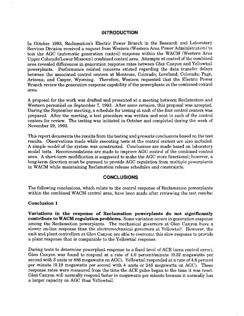
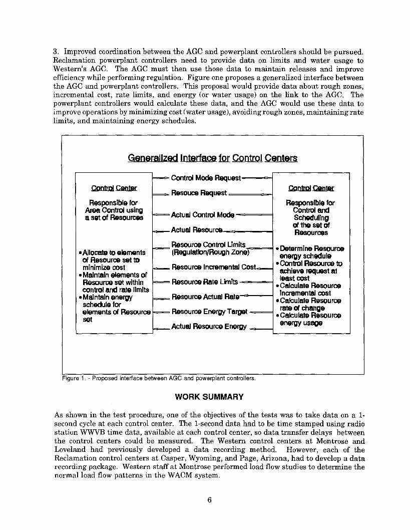
3. Improved coordination between the AGC and powerplant controllers should be pursued.Reclamation powerplant controllers need to provide data on limits and water usage toWestern's AGC. The AGC must then use those data to maintain releases and improveefficiency while performing regulation. Figure one proposes a generalized interface betweenthe AGC and powerplant controllers. This proposal would provide data about rough zones,incremental cost, rate limits, and energy (or water usage) on the link to the AGC. Thepowerplant controllers would calculate these data, and the AGC would use these data toimprove operations by minimizing cost (water usage), avoiding rough zones, maintaining ratelimits, and maintaining energy schedules.
~ Interface for Control Centers
Control CenterResouce Requ
Resource Actu
Control Mode
Responsible forArea Control usinga set of Resources Actual Control
. Alloca1:8 to elementsof Resource set tominimize cost.Maintain elements ofResource set withincontrol and rate limits.Maintain energyschedule forelements of Resourceset
Actual Resour
Resource Con(Regulation/Ro
Resource Inere
Resource Rate
Resource Ene
Actual Resource
Figure 1. - Proposed interface between AGC and powerplant controllers.
WORK SUMMARY
As shown in the test procedure, one of the objectives of the tests was to take data on a 1-second cycle at each control center. The I-second data had to be time stamped using radiostation WWVB time data, available at each control center, so data transfer delays betweenthe control centers could be measured. The Western control centers at Montrose andLoveland had previously developed a data recording method. However, each of theReclamation control centers at Casper, Wyoming, and Page, Arizona, had to develop a datarecording package. Western staff at Montrose performed load flow studies to determine thenormal load flow patterns in the WACM system.
6
The primary purpose for the testing was to determine the response of the Reclamationgenerators and powerplants. Speed level motor run times and on-line governor timeconstants were measured for each available unit. Data from these tests are given under theheading Governor Response in appendix A. The generation step response of each unit isgiven under the heading Unit Control Response. Powerplant step response data are givenunder the heading Plant Control Response. An individual generation setpoint receivedfrom Loveland controls Seminoe and Kortes powerplants. Alcova and Fremont Canyon alsohave an individual generation setpoint. Step response tests were performed for both of thesesetpoint controllers at the Casper Control Center. Step response tests for Yellowtail wereperformed from Casper and Loveland. Step response tests for Glen Canyon were performedat Page.
Response of the AGC was tested by performing two types of tests. First, an ACE pulse wasused to determine the powerplant controlled response. An ACE pulse was sent to Lovelandto observe the Yellowtail response, and an ACE pulse was sent to Page to observe the GlenCanyon response. Second, response of the AGC was tested by introducing a step change inthe WACM tieline schedules at Montrose. These AGC step tests were performed with GlenCanyon and Yellowtail powerplants on AGC.
The primary focus is the powerplant response data given in appendix A. In summary, thepowerplant response from both Yellowtail and Glen Canyon is adequate. The Yellowtail andGlen Canyon step responses were completed within 2 minutes in all cases. The totalresponse to a normal ACE (10 megawatts) pulse was about 4 to 6 percent/minute for bothplants. Under assist conditions (3D-megawatt ACE), Glen Canyon was found to respond at7 to 8 percent/minute.
Mter the testing was completed, a simple model of the system was constructed using alaboratory simulation. The simulation was built to study the drift in the WALM internalscheduled tielines during normal AGC regulation. Descriptions of the model developed andthe laboratory responses are given in appendix B.
LJRRARY
[J~~p28~J8UfiQ\..o,-" f:,,~k.!iT~
~tiO!l~
7

APPENDIX A
AGC Response Test Results
9

AGC TEST DATA
12/10/93S. Stitt
The following test data are divided into five major sections: Governor Response, UnitControl Response, Plant Control Response, Plant Response to ACE, and PlantResponse to a Tieline Schedule Change. Simple explanations of the data taken withsome analysis are given prior to each section.
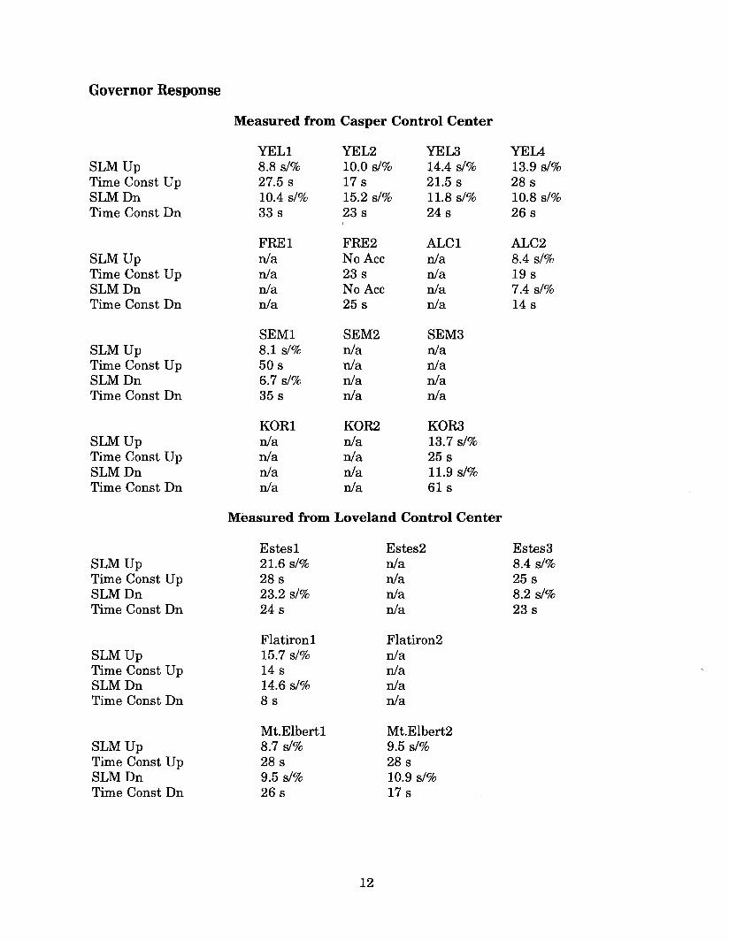
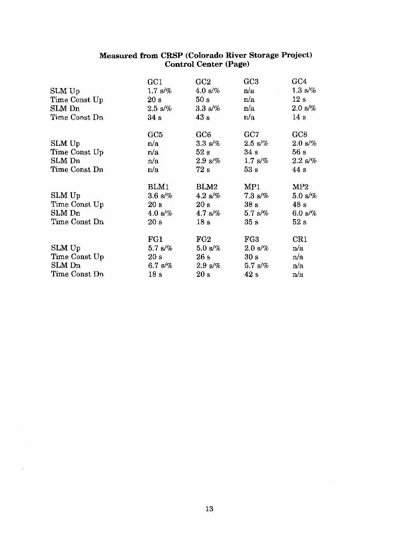
Governor Response
These tests measured speed level motor run time and the governor time constants for eachunit tested. The speed level run times up and down are given in seconds per percent.Normally, 5 percent is considered full travel for the speed level motor, and a 10-second-per-percent travel time is recommended. This time provides good resolution while maintainingresponse time at a reasonable level.
The Upper Colorado speed level motors run much faster than recommended. These fastmotors make controller adjustment more difficult. Project personnel will investigate andcorrect this problem when governor annual maintenance occurs.
The governor time constants were measured by manually stepping the speed level motor upand down from the control board. Therefore, these time constants cannot be considered atrue measurement but are a good approximation. The governors at Glen Canyon are slowerbecause they have no dashpot bypass. However, the generation controls function adequatelywith these slower governors.
Definitions
SLM Up(Dn) -Run time ofthe speed level motor in the raise (up) or lower (down) direction.
Time Const Up(Dn) - Time for generation to move 63 percent (one time constant) of travelin the up or down direction when a step change to the speed level is made manually from thecontrol board.
11
Governor Response
Measured from Casper Control Center
YELl YEL2 YEL3 YEIASLM Up 8.8 s/% 10.0 s/% 14.4 s/% 13.9 s/%Time Const Up 27.5 s 17 s 21.5 s 28 sSLM Dn 10.4 s/% 15.2 s/% 11.8 s/% 10.8 s/%Time Const Dn 33 s 23 s 24 s 26 s
FRE1 FRE2 ALC1 ALC2SLM Up nla No Acc nla 8.4 s/%Time Const Up nla 23 s nla 19 sSLM Dn nla No Acc nla 7.4 s/%Time Const Dn nla 25 s nla 14 s
SEMI SEM2 SEM3SLM Up 8.1 s/% nla nlaTime Const Up 50 s nla nlaSLM Dn 6.7 s/% nla nlaTime Const Dn 35 s nla nla
KOR1 KOR2 KOR3SLM Up nla nla 13.7 s/%Time Const Up nla nla 25 sSLM Dn nla nla 11.9 s/%Time Const Dn nla nla 61 s
Measured from Loveland Control Center
Estes1 Estes2 Estes3SLM Up 21.6 s/% nla 8.4 s/%Time Const Up 28 s nla 25 sSLM Dn 23.2 s/% nla 8.2 s/%Time Const Dn 24 s nla 23 s
Flatiron 1 Flatiron2SLM Up 15.7 s/% nlaTime Const Up 14 s nlaSLM Dn 14.6 s/% nlaTime Const Dn 8 s nla
Mt.Elbert1 Mt.Elbert2SLM Up 8.7 s/% 9.5 s/%Time Const Up 28 s 28 sSLM Dn 9.5 s/% 10.9 s/%Time Const Dn 26 s 17 s
12
Measured from CRSP (Colorado River Storage Project)Control Center (Page)
GC1 GC2 GC3 GC4SLM Up 1.7 s/% 4.0 s/% n/a 1.3 s/%Time Const Up 20 s 50 s n/a 12 sSLM Dn 2.5 s/% 3.3 s/% n/a 2.0 s/%Time Const Dn 34 s 43 s n/a 14 s
GC5 GC6 GC7 GC8SLM Up n/a 3.3 s/% 2.5 s/% 2.0 s/%Time Const Up n/a 52 s 34 s 56 sSLM Dn n/a 2.9 s/% 1.7 s/% 2.2 s/%Time Const Dn nla 72 s 53 s 44 s
BLM1 BLM2 MP1 MP2SLM Up 3.6 s/% 4.2 s/% 7.3 s/% 5.0 s/%Time Const Up 20 s 20 s 38 s 48 sSLM Dn 4.0 s/% 4.7 s/% 5.7 s/% 6.0 s/%Time Const Dn 20 s 18 s 35 s 52 s
FG1 FG2 FG3 CR1SLM Up 5.7 s/% 5.0 s/% 2.0 s/% n/aTime Const Up 20 s 26 s 30 s n/aSLM Dn 6.7 s/% 2.9 s/% 5.7 s/% n/aTime Const Dn 18 s 20 s 42 s n/a
13
Unit Control Response
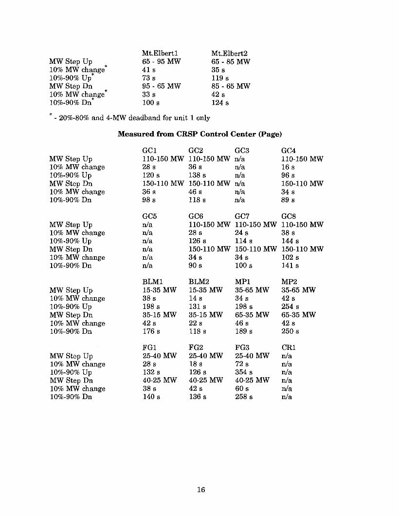
These tests measured the response of the individual units while under setpoint control. Astep change in the generation setpoint was made in the raise and lower directions. Responseto the step change was measured. Two criteria were measured. The first was the time toreach 10 percent of the expected change, and the second was the time to travel from 10percent to 90 percent of the expected change. The response data for some of the unitsindicate some adjustment is necessary. For example, the Morrow Point units and FlamingGorge unit 3 have a slow response. Some coordination in operation of the governor dash potbypasses may be necessary. The controllers at Glen Canyon have an unusually large amountof variation in their responses. In addition, the Mt. Elbert controllers had a large deadband.These problems are not critical, but should be reviewed when annual governor maintenanceis performed.
Definitions
MW Step Up(Dn) -The step change in generation up (raise) or down (lower) sent to the unitcontroller.
10% MW change - The time required to reach 10 percent of the expected generation stepchange.
10%-90% Up(Dn) - The time required for the unit to move from 10 percent to 90 percent ofthe expected response.
14
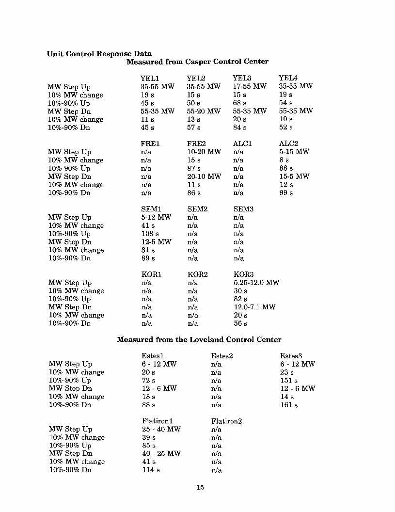
Unit Control Response DataMeasured from Casper Control Center
YELl YEL2 YEL3 YEL4MW Step Up 35-55 MW 35-55 MW 17-55 MW 35-55 MW10% MW change 198 158 158 19810%-90% Up 458 508 688 548MW Step Dn 55-35 MW 55-20 MW 55-35 MW 55-35 MW10% MW change 118 138 208 10810%-90% Dn 458 578 848 528
FRE1 FRE2 ALC1 ALC2MW Step Up n/a 10-20 MW n/a 5-15 MW10% MW change n/a 158 n/a 8810%-90% Up n/a 878 n/a 888MW Step Dn n/a 20-10 MW n/a 15-5 MW10% MW change n/a 118 n/a 12810%-90% Dn n/a 868 n/a 998
SEMI SEM2 SEM3MW Step Up 5-12 MW n/a n/a10% MW change 418 n/a n/a10%-90% Up 1088 n/a n/aMW Step Dn 12-5 MW n/a n/a10% MW change 318 n/a n/a10%-90% Dn 898 n/a n/a
KOR1 KOR2 KOR3MW Step Up n/a n/a 5.25-12.0 MW10% MW change n/a n/a 30810%-90% Up n/a n/a 828MW Step Dn n/a n/a 12.0-7.1 MW10% MW change n/a n/a 20810%-90% Dn n/a n/a 568
Measured from the Loveland Control Center
E8te81 E8te82 E8te83MW Step Up 6 - 12 MW n/a 6 - 12 MW10% MW change 208 n/a 23810%-90% Up 728 n/a 1518MW Step Dn 12 - 6 MW n/a 12 - 6 MW10% MW change 188 n/a 14810%-90% Dn 888 n/a 161 8
Flatiron 1 Flatiron2MW Step Up 25 - 40 MW n/a10% MW change 398 n/a10%-90% Up 858 n/aMW Step Dn 40 - 25 MW n/a10% MW change 418 n/a10%-90% Dn 1148 n/a
15
GC1 GC2 GC3 GC4MW Step Up 110-150 MW 110-150 MW nJa 110-150 MW10% MW change 288 368 nJa 16810%-90% Up 1208 1388 nJa 968MW Step Dn 150-110 MW 150-110 MW nJa 150-110 MW10% MW change 368 468 nJa 34810%-90% Dn 988 1188 nJa 898
GC5 GC6 GC7 GC8MW Step Up nJa 110-150 MW 110-150 MW 110-150 MW10% MW change nJa 288 248 38810%-90% Up nJa 1268 1148 1448MW Step Dn nJa 150-110 MW 150-110 MW 150-110 MW10% MW change nJa 348 348 102810%-90% Dn nJa 908 1008 1418
BLM1 BLM2 MP1 MP2MW Step Up 15-35 MW 15-35 MW 35-65 MW 35-65 MW10% MW change 388 148 348 42810%-90% Up 1988 1318 1988 2548MW Step Dn 35-15 MW 35-15 MW 65-35 MW 65-35 MW10% MW change 428 228 468 42810%-90% Dn 1768 1188 1898 2508
FG1 FG2 FG3 CR1MW Step Up 25-40 MW 25-40 MW 25-40 MW nJa10% MW change 288 188 728 nJa10%-90% Up 1328 1268 3548 nJaMW Step Dn 40-25 MW 40-25 MW 40-25 MW nJa10% MW change 388 428 608 nJa10%-90% Dn 1408 1368 2588 nJa
MW Step Up*10% MW change
*10%-90% UpMW Step Dn
*10% MW change*10%-90% Dn
Mt.Elbert165 - 95 MW41873895 - 65 MW3381008
Mt.Elbert265 - 85 MW358119885 - 65 MW4281248
* - 20%-80% and 4-MW deadband for unit 1 only
Measured from CRSP Control Center (Page)
16
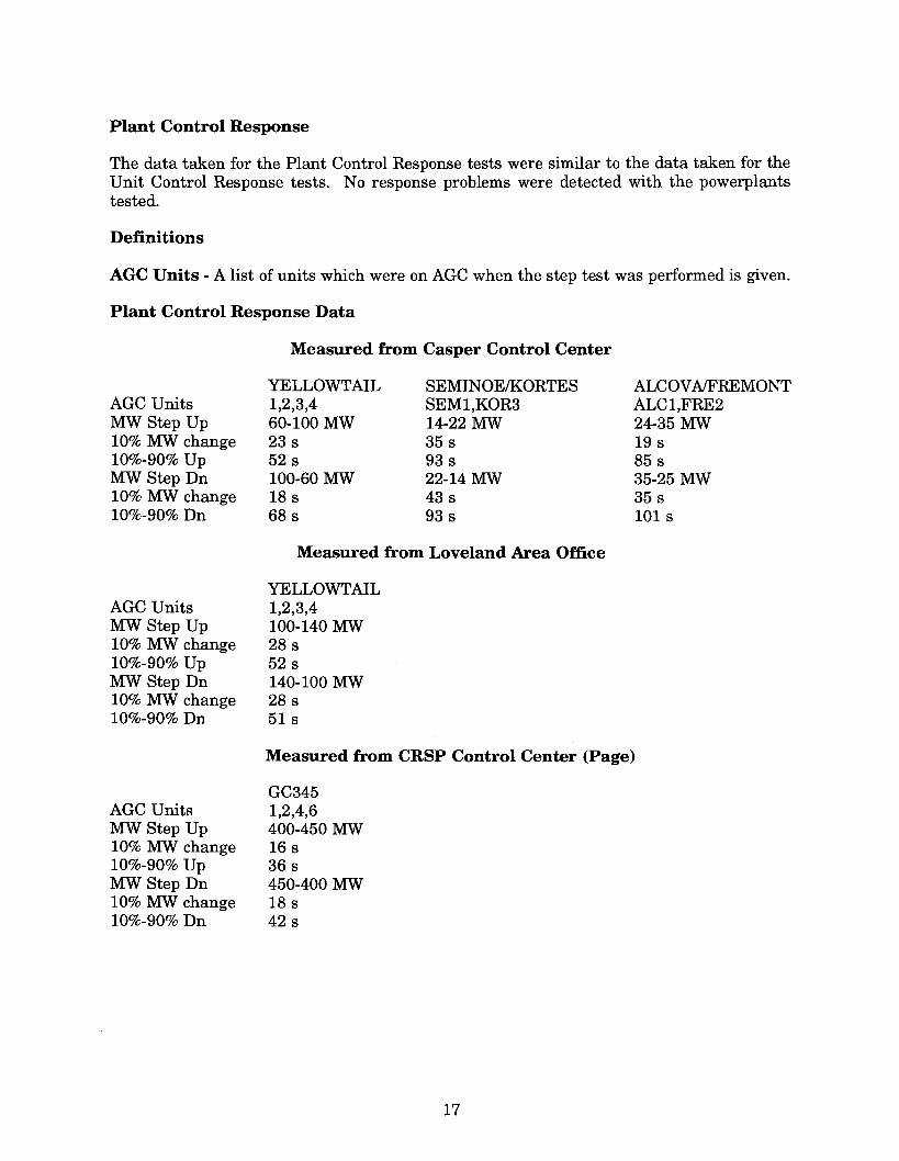
Plant Control Response
The data taken for the Plant Control Response tests were similar to the data taken for theUnit Control Response tests. No response problems were detected with the powerplantstested.
Definitions
AGC Units - A list of units which were on AGC when the step test was performed is given.
Plant Control Response Data
AGC UnitsMW Step Up10% MW change10%-90% UpMW Step Dn10% MW change10%-90% Dn
AGC UnitsMW Step Up10% MW change10%-90% UpMW Step Dn10% MW change10%-90% Dn
AGC UnitsMW Step Up10% MW change10%-90% UpMW Step Dn10% MW change10%-90% Dn
Measured from Casper Control Center
YELLOWTAIL1,2,3,460-100 MW23 s52 s100-60 MW18 s68 s
SEMINOEIKORTESSEM1,KOR314-22 MW35 s93 s22-14 MW43 s93 s
Measured from Loveland Area Office
YELLOWTAIL1,2,3,4100-140 MW28 s52 s140-100 MW28 s51 s
ALCOVA/FREMONTALC1,FRE224-35 MW19 s85 s35-25 MW35 s101 s
Measured from CRSP Control Center (Page)
GC3451,2,4,6400-450 MW16 s36 s450-400 MW18s42 s
17

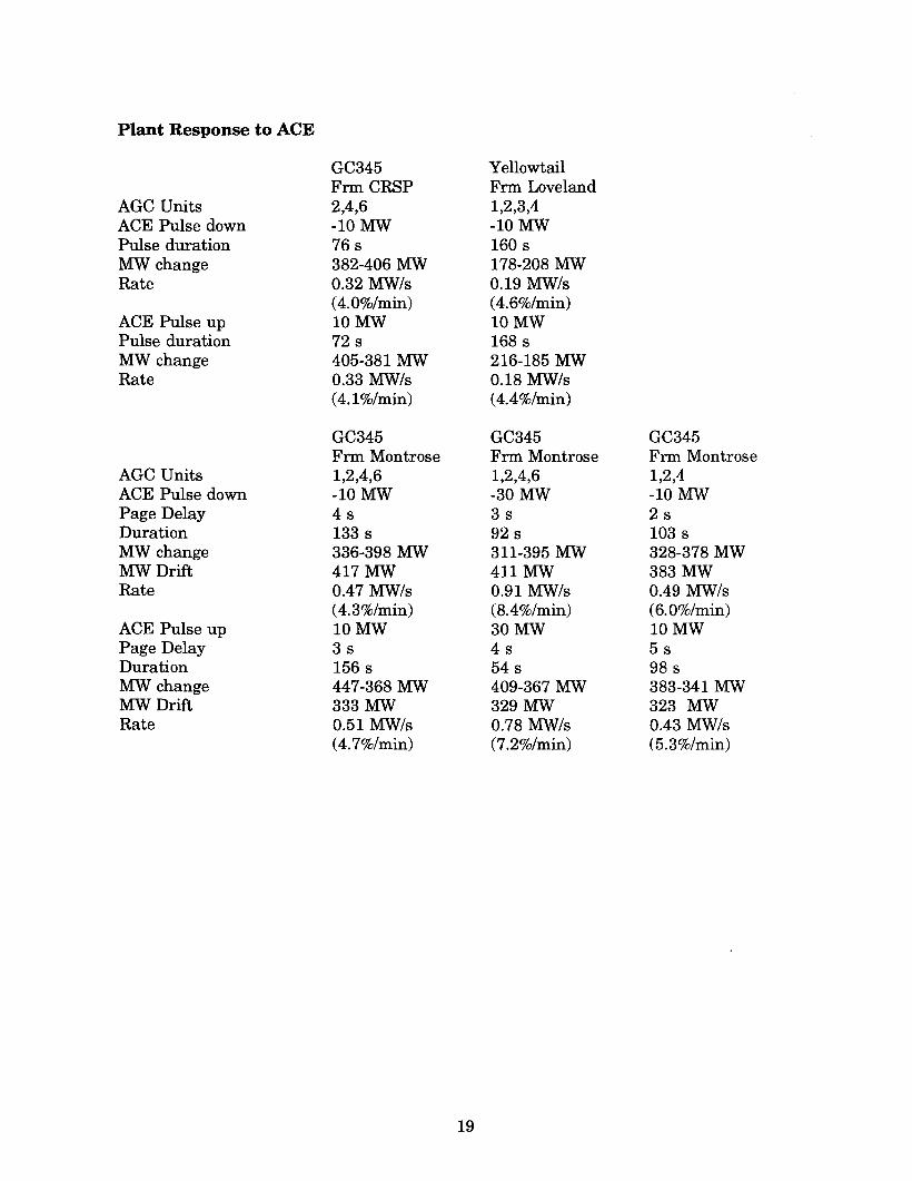
Plant Response to ACE
During this series of tests, an ACE pulse was delivered to each of the powerplants tested tomove generation up and down. No problems with plant response were detected. Thepowerplant response was increased when the pulse amplitude was increased beyond themegawatt assist level. The pulse allowed for convenient measurement of the data transferdelay between the control centers.
Definitions
ACE Pulse down(up) - The level or amplitude of the ACE pulse
Pulse duration - The amount of time the pulse was applied
MW change - The total plant generation change from pulse start to pulse end
Rate - Calculation of the rate the plant moved in megawatts per second
Page Delay -The data transfer delay in seconds between the time the pulse was sent fromthe Montrose control center data base until it reached the Page control center data base
MW Drift - The amount the powerplant continued to drift after the pulse was reset
18
Plant Response to ACE
GC345 YellowtailFnn CRSP Fnn Loveland
AGC Units 2,4,6 1,2,3,4ACE Pulse down -10 MW -10 MWPulse duration 76 s 160 sMW change 382-406 MW 178-208 MWRate 0.32 MW/s 0.19 MW/s
(4.O%/min) (4.6%/min)ACE Pulse up 10MW 10MWPulse duration 72 s 168 sMW change 405-381 MW 216-185 MWRate 0.33 MW/s 0.18 MW/s
(4.1%/min) (4.4%/min)
GC345 GC345 GC345Fnn Montrose Fnn Montrose Fnn Montrose
AGC Units 1,2,4,6 1,2,4,6 1,2,4ACE Pulse down -10 MW -30 MW -10 MWPage Delay 4s 3 s 2sDuration 133 s 92 s 103 sMW change 336-398 MW 311-395 MW 328-378 MWMW Drift 417 MW 411 MW 383 MWRate 0.47 MW/s 0.91 MW/s 0.49 MW/s
(4.3%/min) (8.4%/min) (6.0%/min)ACE Pulse up 10MW 30MW 10MWPage Delay 3 s 4s 5sDuration 156 s 54 s 98 sMW change 447-368 MW 409-367 MW 383-341 MWMW Drift 333 MW 329 MW 323 MWRate 0.51 MW/s 0.78 MW/s 0.43 MW/s
(4.7%/min) (7.2%/min) (5.3%/min)
19

AGC UnitsACE Pulse downPage DelayDurationMW changeMW DriftRate
GC345Frm Montrose1,2-10 MW3 s188 s321-391 MW403 MW0.37 MW/s(6.8%/min)10MW4s141 s403-362 MW341 MW0.29 MW Is(5.4%/min)
ACE Pulse upPage DelayDurationMW changeMW DriftRate
YellowtailFrm Montrose1,2,3,4-10 MWn/a*237 s134-184 MW193 MW0.21 MW/s(5.1%/min)10MWn/a*320 s193-115 MW96MW0.24 MW/s(5.8%/min)
*The data taken at Casper did not allow data transfer delay to be measured during this test.Casper data transfer delay was measured during the tieline schedule change tests. Thisdelay is about 6 seconds from the Montrose data base to the Casper data base.
20
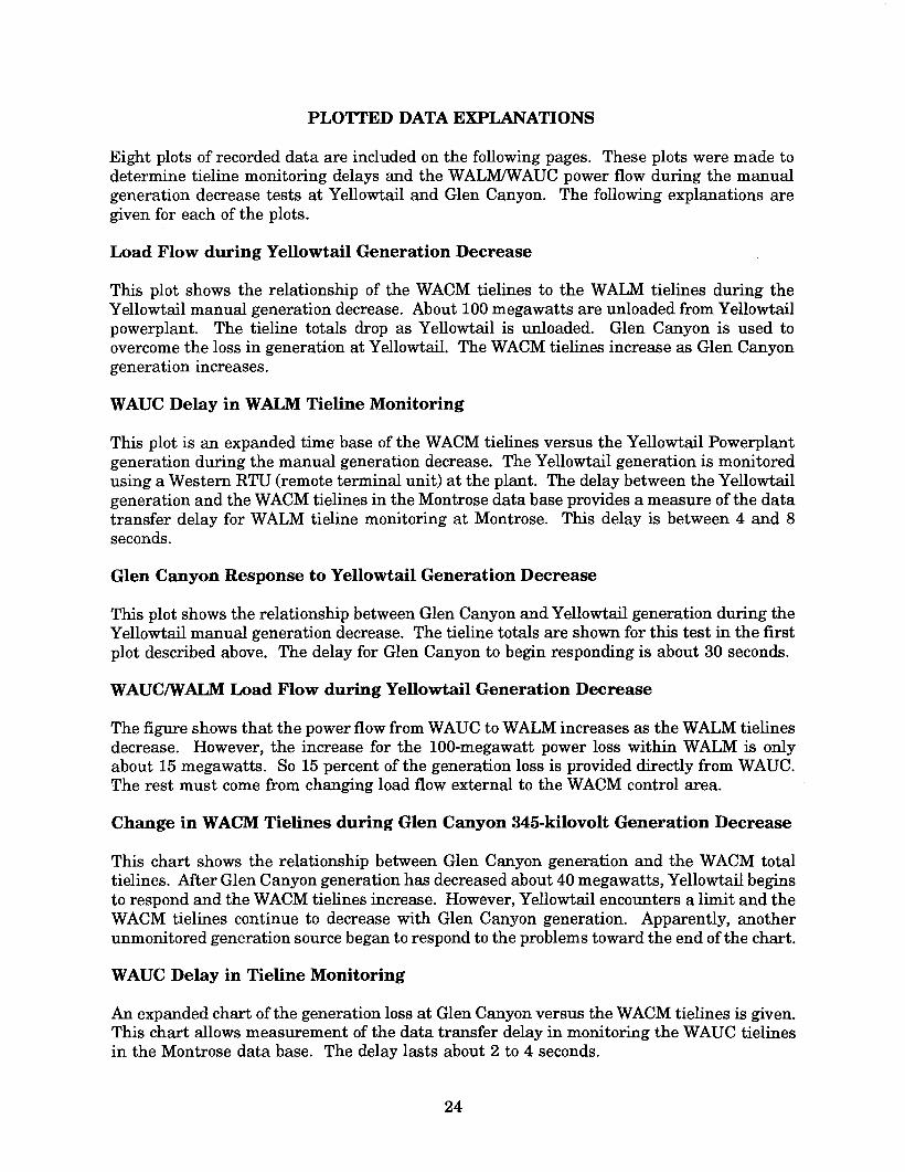
Plant Response to a Tieline Schedule Change
During this series of tests, a change was made to the tieline schedule for the WACM controlarea. The control area response to a step change in the schedule was measured. Thecriterion used was the time for the ACE to cross zero. This test was performed with only theGlen Canyon (345-kilovolt bus) on AGC, with only Yellowtail on AGC, and with both plantson AGC. With both powerplants on control, various configurations of units on control andACE multiplier value were also tested.
Definitions
ACE to Page -The multiplier used to determine what percent ofthe ACE is sent to the Pagecontrol center. With a setting of 0.5, half the ACE is sent to Page and half is sent toLoveland.
MW Tie Offset -The value of the step change, which was normally entered by changing theoffset to a false value and then returning it to O.
ACE Zero Crossing - The time in seconds for the ACE to cross zero.
Glen Response -The change in generation that occurred at Glen Canyon.
Yell Response - The change in generation that occurred at YellowtaiL
21

Plant Response to Tieline Schedule Change
AGC UnitsACE to PageMW Tie OffsetACE Zero CrossingMW Tie OffsetACE Zero Crossing
Frm MontroseGC345 1,2,4,61.00 to -100 MW128 s-100 MW to 0120 s
Frm MontroseGC3451,21.00 to -50 MW104 s-50 MW to 084 s
Frm MontroseAGC Units Yell 1,2,3,4ACE to Page 0.0MW Tie Offset 0 to -70 MWACE Zero Crossing 98 s*MW Tie Offset 0 to -50 MWACE Zero Crossing 103 s**
*Oscillatory with 35-MW ACE overshoot**Oscillatory with -51-MW ACE overshoot
Note: The Loveland settings for Regulation Gain (from 1.1 to 1.0) and Assist Gain (from 1.25to 1.0) were moved before the second series oftests was performed. This movement correctedthe oscillation.
AGC UnitsFrm MontroseGC345 1,2,4,6Yell 1,2,3,40.5-10 to 50 MW86 s502-461 MW (66%)176-155 MW (34%)50 MW to 090 s463-490 MW (63%)151-167 MW (37%)
ACE to PageMW Tie OffsetACE Zero CrossingGlen ResponseYell ResponseMW Tie OffsetACE Zero CrossingGlen ResponseYell Response
AGC UnitsFrm MontroseGC345 1,2Yell 1,2,3,40.50 to -50 MW109 s468-497 MW (56%)168-191 MW (44%)-50 MW to 0125 s497-464 MW (55%)190-163 MW (45%)
ACE to PageMW Tie OffsetACE Zero CrossingGlen ResponseYell ResponseMW Tie OffsetACE Zero CrossingGlen ResponseYell Response
Frm MontroseYell 1,2,3,40.00 to -50 MW104 s (Casper Delay=6 s)-50 to 20 MW114s
Frm MontroseGC345 1,2,4,6Yell 1,2,3,40.20 to -50 MW103 s495-515 MW (33%)161-202 MW (67%)-50 MW to 098 s515-484 MW (41%)205-160 MW (59%)
22
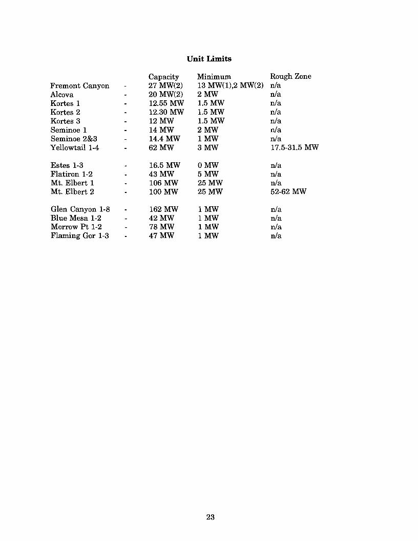
Unit Limits
Capacity Minimum Rough ZoneFremont Canyon 27 MW(2) 13 MW(1),2 MW(2) n/aAlcova 20 MW(2) 2MW n/aKortes 1 12.55 MW 1.5 MW n/aKortes 2 12.30 MW 1.5 MW n/aKortes 3 12MW 1.5 MW n/aSeminoe 1 14MW 2MW n/aSeminoe 2&3 14.4 MW 1MW n/aYellowtail 1-4 62MW 3MW 17.5-31.5 MW
Estes 1-3 16.5 MW OMW n/aFlatiron 1-2 43MW 5MW n/aMt. Elbert 1 106 MW 25MW n/aMt. Elbert 2 100 MW 25MW 52-62 MW
Glen Canyon 1-8 162 MW 1MW n/aBlue Mesa 1-2 42MW 1MW n/aMorrow Pt 1-2 78MW 1MW n/aFlaming Gor 1-3 47MW 1MW n/a
23
PLOTIED DATA EXPLANATIONS
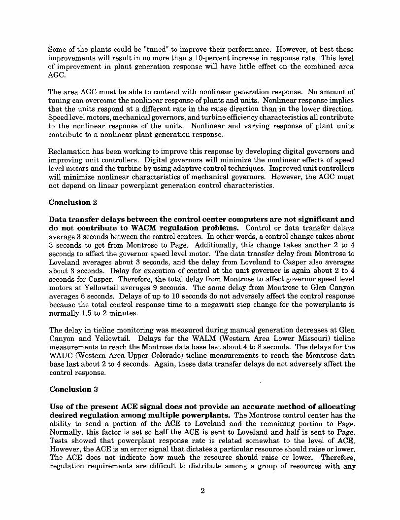
Eight plots of recorded data are included on the following pages. These plots were made todetermine tieline monitoring delays and the WALM/W AVC power flow during the manualgeneration decrease tests at Yellowtail and Glen Canyon. The following explanations aregiven for each of the plots.
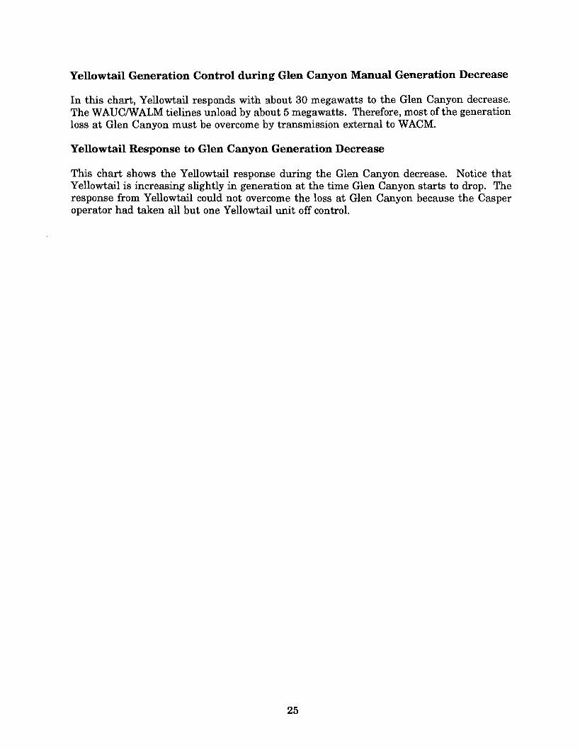
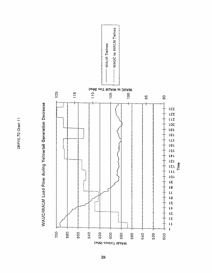
Load Flow during Yellowtail Generation Decrease
This plot shows the relationship of the WACM tielines to the WALM tielines during theYellowtail manual generation decrease. About 100 megawatts are unloaded from Yellowtailpowerplant. The tieline totals drop as Yellowtail is unloaded. Glen Canyon is used toovercome the loss in generation at Yellowtail. The WACM tielines increase as Glen Canyongeneration increases.
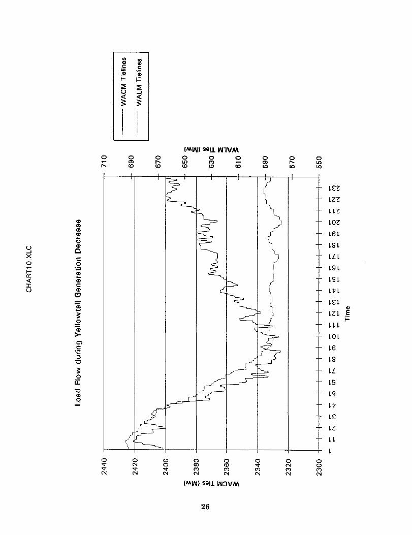
WAUC Delay in WALM Tieline Monitoring
This plot is an expanded time base of the WACM tielines versus the Yellowtail Powerplantgeneration during the manual generation decrease. The Yellowtail generation is monitoredusing a Western RTU (remote terminal unit) at the plant. The delay between the Yellowtailgeneration and the WACM tielines in the Montrose data base provides a measure ofthe datatransfer delay for WALM tieline monitoring at Montrose. This delay is between 4 and 8seconds.
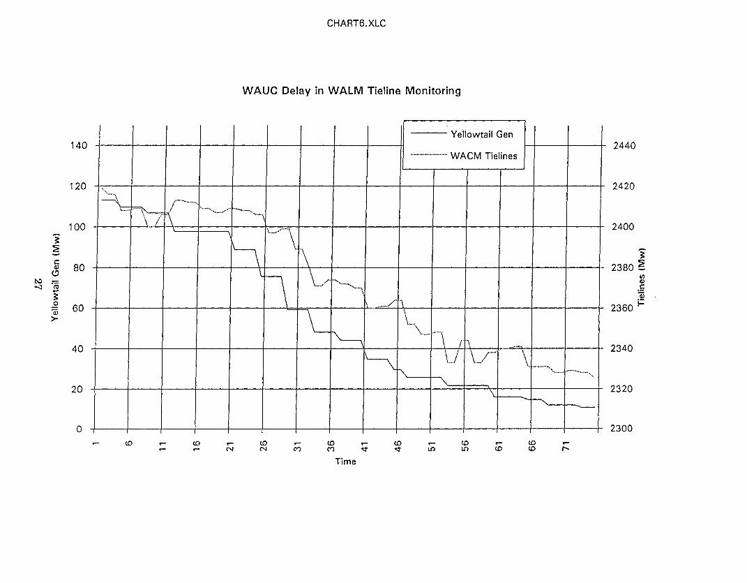
Glen Canyon Response to Yellowtail Generation Decrease
This plot shows the relationship between Glen Canyon and Yellowtail generation during theYellowtail manual generation decrease. The tieline totals are shown for this test in the firstplot described above. The delay for Glen Canyon to begin responding is about 30 seconds.
WAUC/w ALM Load Flow during Yellowtail Generation Decrease
The figure shows that the power flow from WAVC to WALM increases as the WALM tielinesdecrease. However, the increase for the 100-megawatt power loss within WALM is onlyabout 15 megawatts. So 15 percent of the generation loss is provided directly from WAVC.The rest must come from changing load flow external to the WACM control area.
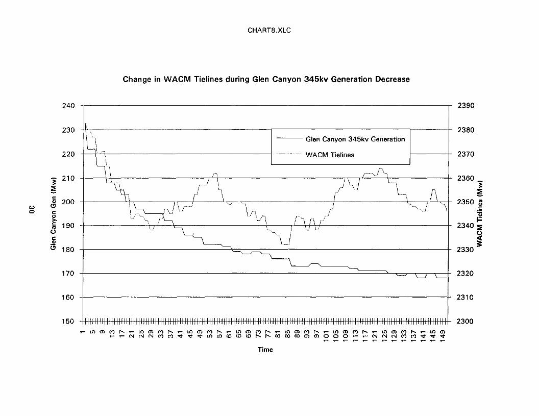
Change in WACM Tielines during Glen Canyon 345-kilovolt Generation Decrease
This chart shows the relationship between Glen Canyon generation and the WACM totaltielines. Mter Glen Canyon generation has decreased about 40 megawatts, Yellowtail beginsto respond and the WACM tielines increase. However, Yellowtail encounters a limit and theWACM tielines continue to decrease with Glen Canyon generation. Apparently, anotherunmonitored generation source began to respond to the problems toward the end ofthe chart.
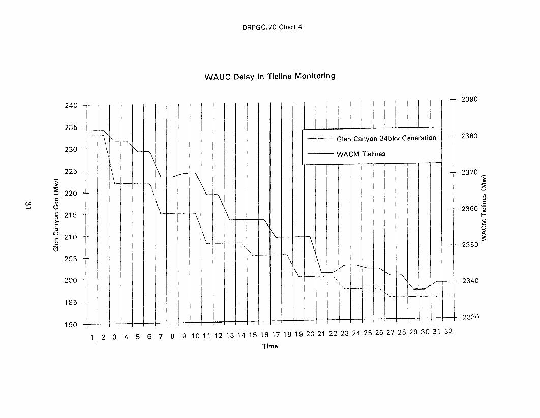
WAUC Delay in Tieline Monitoring
An expanded chart of the generation loss at Glen Canyon versus the WACM tielines is given.This chart allows measurement of the data transfer delay in monitoring the WAVC tielinesin the Montrose data base. The delay lasts about 2 to 4 seconds.
24
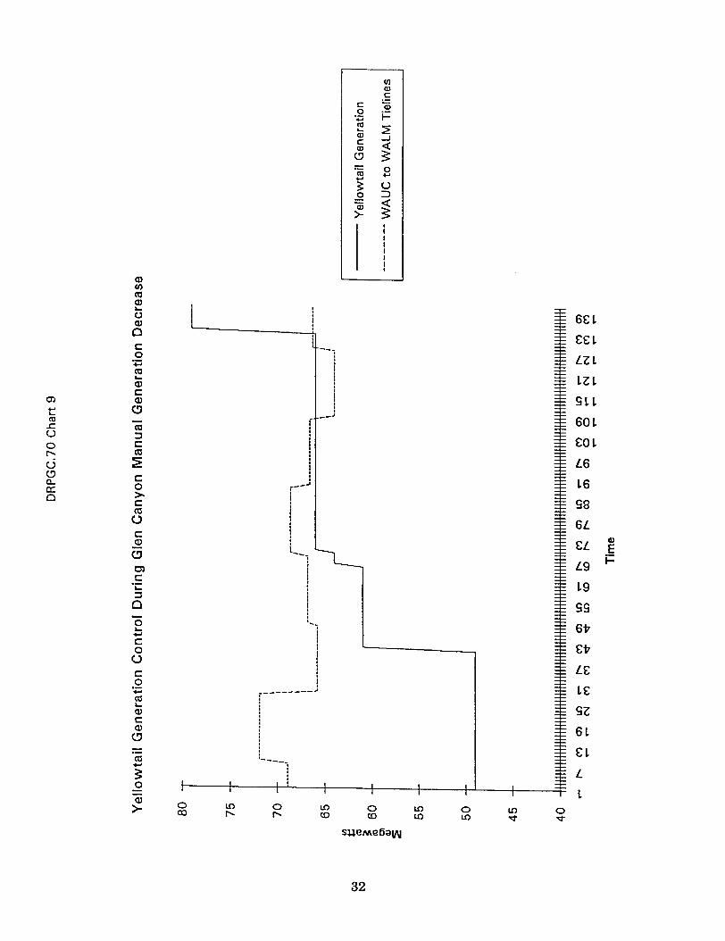
Yellowtail Generation Control during Glen Canyon Manual Generation Decrease
In this chart, Yellowtail responds with about 30 megawatts to the Glen Canyon decrease.The WADC/WALM tielines unload by about 5 megawatts. Therefore, most of the generationloss at Glen Canyon must be overcome by transmission external to WACM.
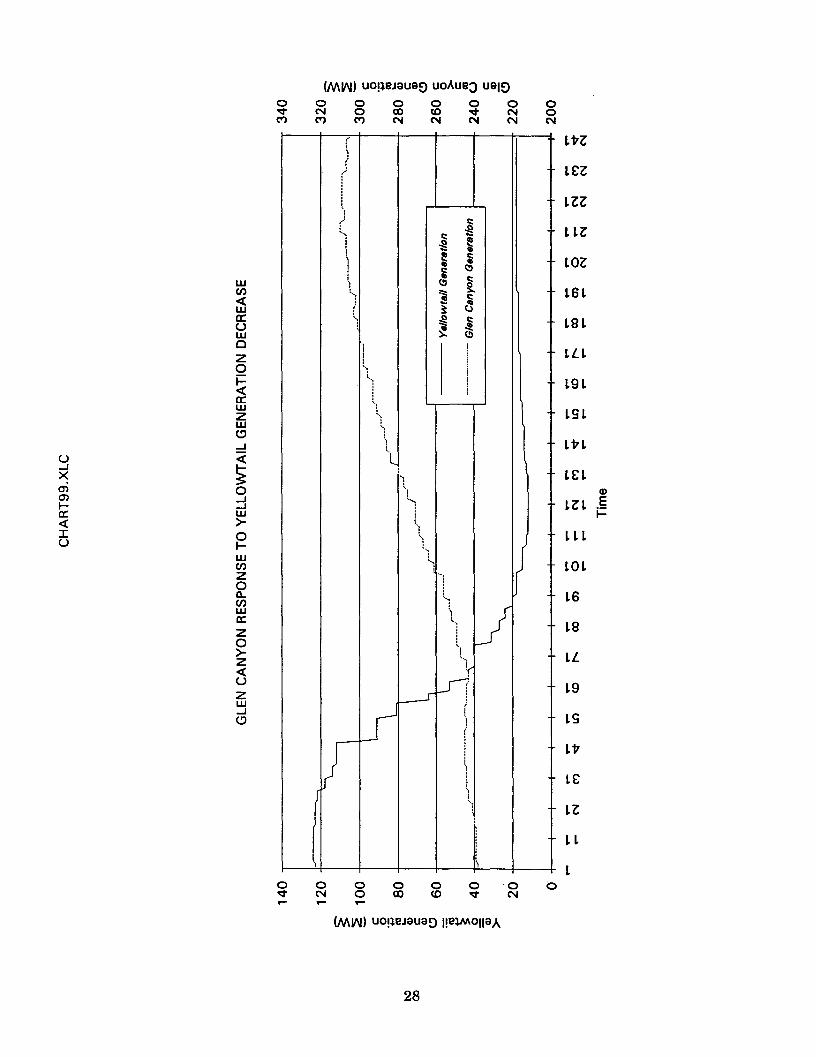
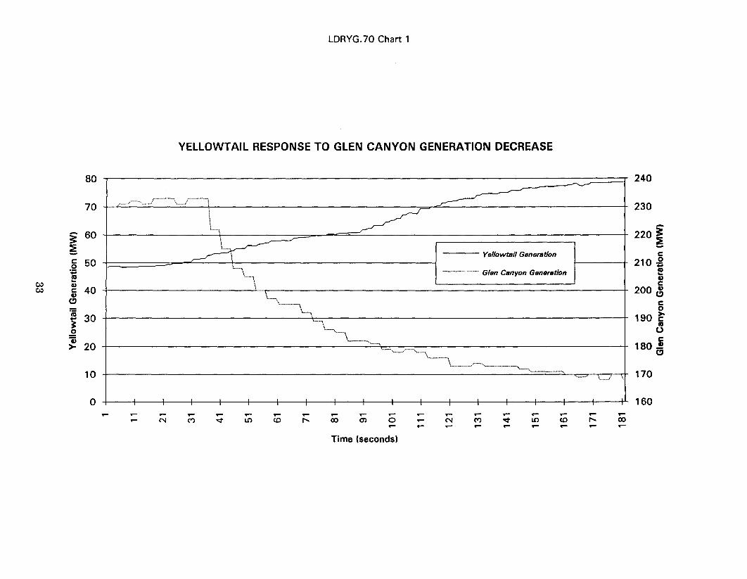
Yellowtail Response to Glen Canyon Generation Decrease
This chart shows the Yellowtail response during the Glen Canyon decrease. Notice thatYellowtail is increasing slightly in generation at the time Glen Canyon starts to drop. Theresponse from Yellowtail could not overcome the loss at Glen Canyon because the Casperoperator had taken all but one Yellowtail unit off control.
25
(MIN) S9!J. W1VM0 0 0 0 0 0 0 0 0.... en I' It) M .... en I' It)I' <0 <0 <0 <0 CO 1.0 1.0 1.0
r)L£Z;
'! LZZ",
'1 LLZ'-.Q)
.-' LOZ(I)./as ,;
L6 LQ)(a..
CJl La Lu
Q)
...J 0 ~jLLL>< c: ;
0 0L9L.... +:iI- asc: a.. L9 L« Q)
(::r: c:LvLu Q)
0.- L£ Las ~CD....
LZL E~/' i=.2 LLLQ)
> LOLC)
L6c:.~~La
'C~LL
0L9u:
'C L9as0
Lv..J
L£
LZ
L L,
L0 0 0 0 0 0 0 0~N 0 ex> <0 ~N 0
~~-=t M M M M MN N N N N N N N
(MIN) sa!J. II\I~VM
26
II)CD.=CDi=~u
~
II)CD
.=CDi=~...J
~
100
~~c
80Q,)
'"~'ro-..:r+-'~0
604j>-
40
Yellowtail Gen
"".'.'.''''''''''''.'' WACM Tielines
"".'\~/..............
\- ~'"",,,,,.......,,,..,,,. '''-....,\.-...
\.../ "\-....\
\.-.,....,....\\
\ \.\
\. \
1 \ /. .,....,." """'''''....-.,
\
\ F'\..........'
L'"
\...~\,.........\ r, ... ,..,...
\.../ \./""\
~""\.
""""-'" ~'-'''''''''-''"'\.
\--......
-
CHART6.XLC
WAUC Delay in WALM Tieline Monitoring
140
120
20
0CD CD
U)....CD
CDCD
CDN
CD ....C'1 <;t
Time
CD<;t
CD ....,.....
....C'1
....U)
....
........N
2440
2420
2400
~2380 ~
CI1Q,)
.£:4j
2360 i=
2340
2320
2300
,
~(
rr) c::l" c:: .~t .g ;'j e iIII t!)
i c::, t!)~~'1 .!~Ir~'j ,5! c::
~~: t!)
i
;,
,",
II '!!
~'.
'":)'OJ
""' :i'll.
~'.
~','1
-1
':
lJ')
'1't...
~Ls1(
J ")
I
V']
'1.
:,
\
u-'xenenI-a::«IU
0~M
(MV>.I) UO!~eJ9U9D uoAueJ U91D
0 000 0 0('oj 0 CO CO ~ ('ojM M ('oj N N ('oj
wCJ)«wa:uwCZ0t=«a:wZwCJ-'
~0-'-'w>-0I-wrnz0Il.CJ)Wa::z0>-z«uzw-'CJ
0~....
0N....
00....
0co
0co
0~
0('oj
(MV>.I) UO!~eJ9U9D l!eVAOn9A
28
00N
Lvl
L£l
Lll
LLl
Lal
L6 L
La L
LLL
L9 L
L9 L
Lv L
L£LQ)
Ll L .5I-
LLL
LaL
L6
La
LL
L9
L9
Lv
L£
Ll
LL
L0
U)OJC-OJ
i=
~U) -IQ) <{c~-Q)
t= 0...
~U-I :::><{ <{
(MII\I) sa!l. II\ITvM o~ ~m/M0 L!) 0 L!) 0N ..- 0 0 L!) 0..- en 0)
Q)en
-----'l£ZroQ)
lZZ~()Q)
-l lLZ0... c:
lOZ.... 0co+J
l6l.cu ro
~lSl0 OJ...... c:w OJ
lL l>- (!)
19lQ...a: .-0 ro
lS l+oJ
L::
l Vl0Q)
l£l>-~C)
lZ l Ec: j::~"1 III:J
"'0lOL::
r ---l
l60u.
lS"'0
lLro0
...J19~lS...J
c:::(LvS ---
---L__,l£-()lZ~c:::(
IISl
0 0 0 0 0 0 0 0 0 0 00 co <D ~N 0 co <D ~N 0...... <0 <D <D <D <D L!) L!) L!) L!) L!)
(MIJ\I) sau!la!!. IJ\ITvM
29
240
230
220
- 210
~~c:
CI) 200c."
e,:,0 c:
0>-c: 190It!
uc:CI)a 180
170
160
150
CHART8.XLC
Change in WACM Tielines during Glen Canyon 345kv Generation Decrease
.;/.\
Ir-'.'.I
ir'!
,
\i\'-.::7'.'.' '...~
i\ f"'.I \ ...j
\.I ,\\ ,1."" i
"'\ I\ 1
\../.
/111111111111111111111111111111111
Glen Canyon 345kv Generation
WACM Tielines
/, /1""'\,\
;'~'!'" I
rj \'\...iri
ji
r!.,./
r--\ ri rj- \.1 U
,
\i f1\ , I \i. .L l.
I.." j "...,
<""""' 1 \
~~mM~~~mM~~~mM~~~mM~~~mM~~~mM~~~mM~~~~~~NNNMM~~~~~~~~~~oooooommOOO~~NNNMM~~~
Time'1""'8.--.--.--...........--.--.................-.....
2390
2380
2370
2360j~-
2350 ~.5"iii=
2340 ~0<
2330;:
2320
2310
2300
235
230
225 -'"i
~220 -c~(1)
..... (.!)
c 215 -0>-c(\Ju 210c -(1)
a205 -
200 -
195 -
190
240 ,... I
-~\"-~
\ ~I\
\ ~-I ' '"
...\
\\... ,. .-.\
\
DRPGC.70 Chart 4
WAUC Delay in Tieline Monitoring
I
\
~I\\
\... ' ...~
'"
\\
I I
1 2 3 4 5 6 7 8 9 10 11 12 13 14 15 16 17 18 19 20 21 22 23 24 25 26 27 28 29 30 31 32
I ""'.'.'.""""""." Glen Canyon 345kv Generation
WACM Tielines
\.,'\\ ,... ...\
\, ~ -I-. r-~\.. --: '- ~
" v-~"""".' '.'.'." '.""'"
"""'-L..-/
Time
"' ,u...
'-''''''''
,
"
, ...,..
-r- 2390
- 2380
-~ 2370~~
-
LI)(1)
c2360 ~
i=~uex:;:
2350
2340
2330
Q)U)
<0Q)
~()Q)
CIc:0
+::<0~Q)
c:0) Q).... C)'-co.L:. <0U~0 c:
"<0
U :2:<.:J c:a.. 0a:0 >-
c:<0
t)
c:Q)
C)
enc:
0;:
~CI
0~....c:0
t)
c:0
o~<0~Q)
c:Q)C)
0-<0....
~0
Q)0
>- ex)
<IIQ)c
c Q)0
i=.~CO~'-Q)
...JC «Q)
<.:J 3.- 0co ........3: u.2 ::JQ)
~>-IIIIIII.
6£l
££l--- ,
LZl',
! lZlI::
9 III,I-_J
60lf
£Ol
! L6II:
l6.r--.JII
98!
I
6L
£LII),El__.i=I
L9I:i
19I
!I
99~.
6t-.! £t
! L£! l£---------'
f 9Z
i
6l
£l'----1
L
ll!') 0 l!') 0 l!') 0 l!') 0" " <0 <0 l!') l!') <o;t <o;t
su.eMe6al/ll
32
80
70
i 60:E-c:: 500
"~10C/.:) ...Q)C/.:) c:: 40Q)
e""jij
30i.2"i)
20>
10
0....
I' 160, , ,
.... .... .... .... .... .... .... .... .... .... .... .... .... ....
.... C'I C") '<t Ln (() ..... 00 0') 0 .... C'I C") '<t Ln <0 ..... 00.... .... .... .... .... .... .... .-
Time (seconds)
LDRYG.70 Chart 1
YELLOWTAIL RESPONSE TO GLEN CANYON GENERATION DECREASE
..n..."""""''''''''/'''''''''''''\"I
nO"
\i-un\
---~\...U\
"U"\\
UU\
,\ \
\ ,
~
~
~Yellowtail Generation
""''''''''''''''''''''''''Glen Canyon Generation
"'U\.....
\ , ,"---", ..-un.".
""'"n,
"
\"""""""""""""""""'''''''-''''-''......."""""'''-'''''''' "...n"
""'\ / -..'''\
240
230
220 i~c::
210 ~«J...I)c::
200 ~c::0
190 ~«J0c::
1 80 .!!e"
170


APPENDIX B
Initial Model and Simulation
35

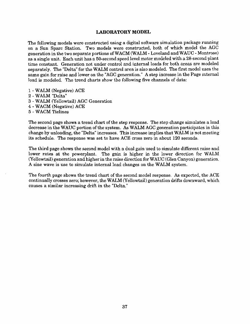
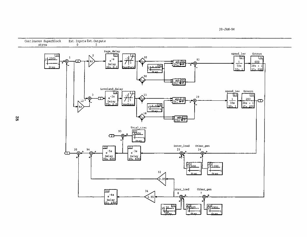
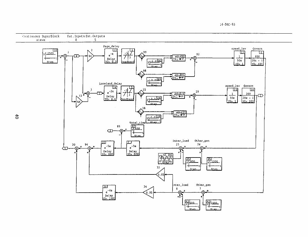
LABORATORY MODEL
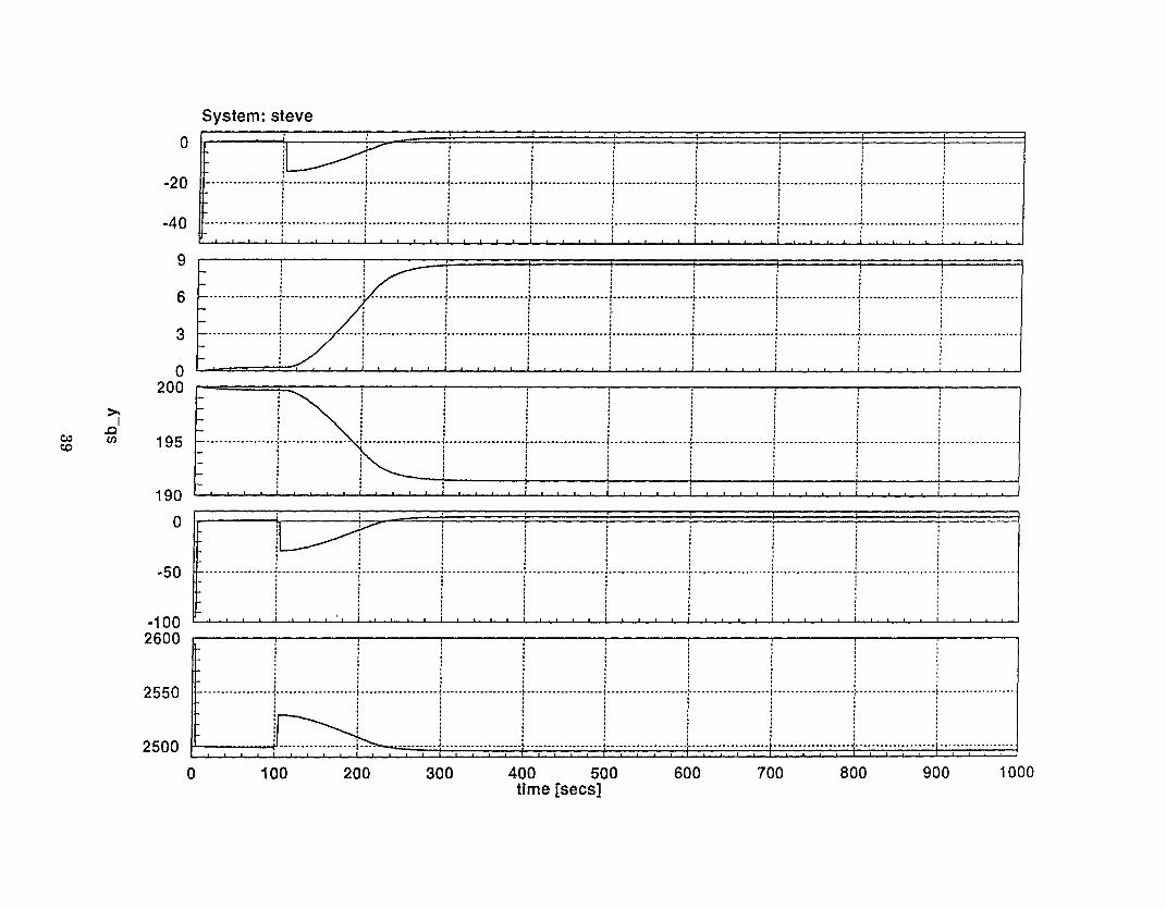
The following models were constructed using a digital software simulation package runningon a Sun Sparc Station. Two models were constructed, both of which model the AGCgeneration in the two separate portions ofW ACM (WALM -Loveland and WAVC -Montrose)as a single unit. Each unit has a 50-second speed level motor modeled with a 28-second planttime constant. Generation not under control and internal loads for both areas are modeledseparately. The "Delta" for the WALM control area is also modeled. The fIrst model uses thesame gain for raise and lower on the "AGC generation." A step increase in the Page internalload is modeled. The trend charts show the following fIve channels of data:
1 -WALM (Negative) ACE2 -WALM "Delta"3 -WALM (Yellowtail) AGC Generation4 -WACM (Negative) ACE5 -WACM Tielines
The second page shows a trend chart of the step response. The step change simulates a loaddecrease in the WAVC portion of the system. As WALM AGC generation participates in thischange by unloading, the "Delta" increases. This increase implies that WALM is not meetingits schedule. The response was set to have ACE cross zero in about 120 seconds.
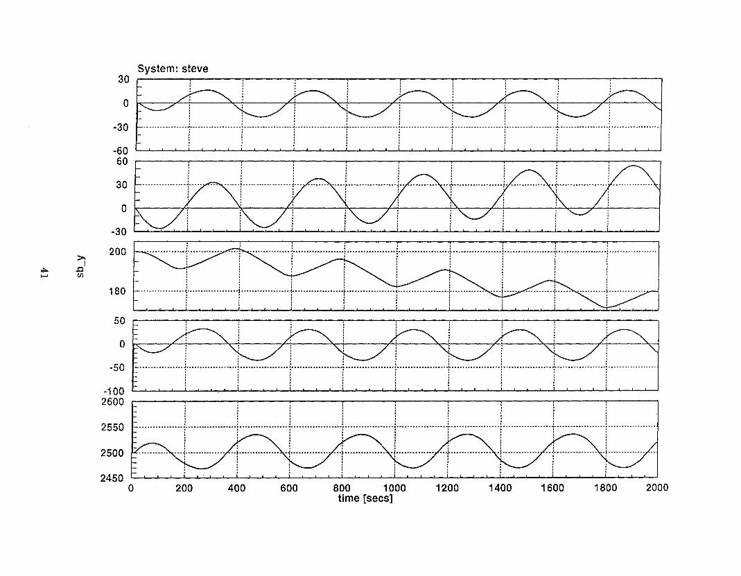
The third page shows the second model with a dual gain used to simulate different raise andlower rates at the powerplant. The gain is higher in the lower direction for WALM(Yellowtail) generation and higher in the raise direction for WAVC (Glen Canyon) generation.A sine wave is use to simulate internal load changes on the WALM system.
The fourth page shows the trend chart of the second model response. As expected, the ACEcontinually crosses zero; however, the WALM (Yellowtail) generation drifts downward, whichcauses a similar increasing drift in the "Delta."
37
20-JAN-94
Continuous SuperBlocksteve
Ext. Inputs Ext. Outputs0 5
C/.:)00
Loveland_delay
'l'oLal_Lies
34
0.95
92
+ ~
29
+
Inter_load23
~ +
+
Other_gen
24~ +
+
32
Othecgen7
~ +
speed_lev7
Govern
speed_lev
200
28s + 1
YO= 200
0
-20
-40
9
6
3
0200
>j.c
C/:) C/) 195c.o
190
0
-50
-1002600
2550
2500
0
System: steve,
I I,
I , I,
II'
I I I , II I I
,I I I ,
II I t t I I I I ,I . I I I . I I ,: : : : : : : : :~ t ~ ~ i ~ i : i .....I I I I I I t I II . I I I t I , II I I I I I I I ,I . I I , I I , ,I I I I I I . I II I
It' I I I ,I I I I , I I I ,I I I I I I I I I-"':-"""""""""""""".-"" t ~ -~ ~ -~ : ~ ~ -"'", t I I I , I , ,I I I I . I I I I
, ,I I I I ,
I I ,I I I I I I I
;:,' .
:"I I I I , I II I I I I I II I I I I I tI I I I I I I
I"."'." ~ ..""""'."".""
~ i t : ~ ~.."".""."""."""'"''''
~~~~~~~~~~~~~~~~~
:
.::,
C~~~~~~~~~""."i ~ I~.
II! !.. : ~ ~.."""..""..".'''...'' ~ : ~ ~ :.. -".""..I I I I I I I .I I . I I I I II I I I I I . II I t I I I I .. I I I I I . .I I I . I I I I
,,.,,..,,'.. 'r""""
' "
I I I . I I . II I I I . I I II I I I . I I II I I I I I I .I I I I I I I II I I t I I I II . I I I I I .I I I I I I I II I I I I I I tt I I I t I I II I . I I I I II I . I I I I .
..~ ~ ..~ """.."..""".." ~ ~ ~ ~ ~.-"""".""."""
.I I I I I I .I I I I I I .I I I I I I II I I I I I It I I . I . ,
! i ! ! ! ! :
. I I I I t I .I I I I I I I II I I I I I I
,I
I I I I I I I I II I I I I I I I II I I I I I I I II I I I I I I I II I I I I I I . II I I I I I . I I. I I I I I I . ,I I I I I I I . ,
.. "".""""""""" "".""""" ~... """"."" "."""""" , ""."""""".."",,,,,,,, """"""""."""""""'''.'''..'.''-
"I I I I I I I I
,
I . I I I I I I II I I I I I I I II I I I
,I I I
,
I I I I I I I I I. I I I I I I I ,. I I I I I I , .I I I I I I I I .I I I I I I I I
,
I I I I I I I I I
I I I I I I I I,
I I I I I I I I II
,I I I I I I I
I I I I I I I I,
,I I I I I I .
,I I , I I , . , ,
1 ! ! i i ! i ! j""""""""""""..."i t "i t.."".."."" ".."1..""""'''''''''''''''".".""1"""""..".""""""."..t ! t".""""".".".."...,.
! ~ ; i j i ! i ~I I I I
,I I I t: : : : : : : : :
J ,J ""..".""""""..""""
' ' ",,"..."""."'''''.''.
100 200 400 500time [sees]
800 1000600 700 900300
14-DEC-93
Continuous SuperBlocksteve
~0
Ext. Inputs Ext ,Outputs0 5
92
+ T.
Loveland_delay
29
+
Other_gen24
T. +
+
34
0.95
speed_lev7
Govern
Govern
0
-30
-6060
30
0
-30
200>;
>!:>- .of-'
(J)
180
50
0
-50
-1002600
2550
2500
24500
30System: steve
I I I . ,I I I I
,
I I I I II . I I I I . . II I I t I I I I II I I I I
,I I I, . I I I I It.
I . I I I I I I ,
.- ~ ~ 4 ""."~."""""""""."""."""'''''''''''''''-''''''.'''''''''' .~ ...............................I . . I I , , I II I I I I I I I II I I I I , I t II I I I t I I
, ,I I I I I I , I
,I I I I I I I I I. , I I I I I I I
..1 ........,,,.
, ,, ,, ,, ,, ,, ,, ,1 ,1......., ,, ,, ,, ,, ,,
, ,, ,, ,, ,, ,, ,, ,
"I"""""""""""."""""".
. ,, ,. ,
-..+ u!..
, ,, ,, ,, ,, ,, ,, ,
' i.., .,
I I I : I : :I I I I I I ,~ ~...",,,,,,,,,,,,,,,,,,,,,,,,,,,,,,,~ "-: ~ ~ ~.--...-.---..-.-.---I I f I , , I ,I I t I , ,I I I I I I
I I I I I I I II
,I I I I I
,
. I I'I I"
i : : ! ,,! : ::, : ::,'I : ,: :
I I'I
I, "'"~ ... -.. -I,
'''''''' ""~ ~ "'"'' ...,..
i"" "''''''''''''.t I ': : : : I :
: -"''' ::,:.-.''--..------
I I , . I II , I I , IIt'
, I I
,1-................
I I I . .I I I I II I I . II I I I II I I I I I I I II I I . I I
, I II
,I I ,
I I I It I
,I I
,I I I
~ t ~ 1.""""..".""""""."""".".."""""".".."" t t..........--.....-......--... I I I I I I I .I I I I I I . I fI I I I I f I , II I I I I I I I II I I I . . I I II I . . I , I I II I
,I I I I I I
200 400 1400 20001600 1800600 800 1000time [sees]
1200


Mission
The mission of the Bureau of Reclamation is to manage, develop, and protect water and related resources in an environmentally and economically sound manner in the interest of the American Public.