Embed Size (px)
Citation preview

Report of Internship in Guo-Lab (CIOMP)
丛聪 Cong CONG

1. A brief introduction of the lab

My topic: Femtosecond Laser Induced Periodic Surface Structure. (LIPSS)
Purpose: Change capability of different material.
Gold aluminum, blue titanium and gold platinum produced by using laser
Black metal produced by using laser
Hydrophobic material rendered by using lasers

a) A new discover: diffraction induce peculiar LIPSS (can be published)
b) A software based on Matlab: Ripples-Recognizer
c) A integrated controller program based on Labview
My work there
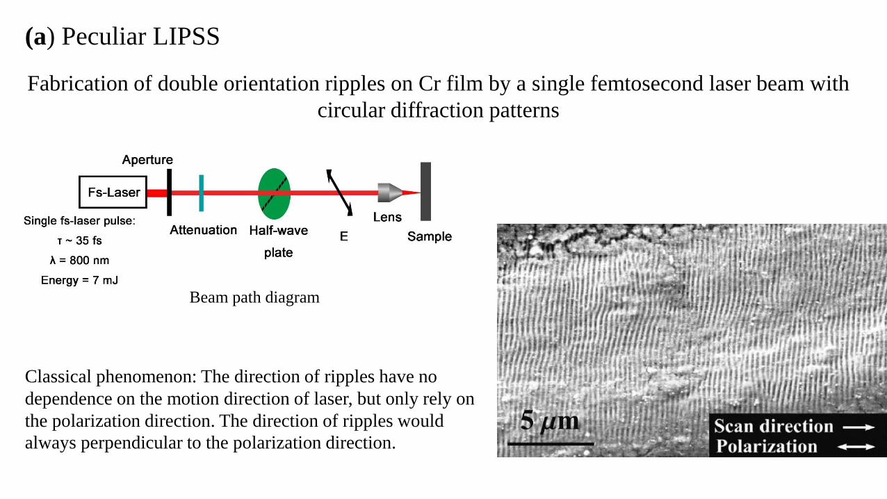
(a) Peculiar LIPSS
Beam path diagram
Classical phenomenon: The direction of ripples have no
dependence on the motion direction of laser, but only rely on
the polarization direction. The direction of ripples would
always perpendicular to the polarization direction.
Fabrication of double orientation ripples on Cr film by a single femtosecond laser beam with
circular diffraction patterns

SE
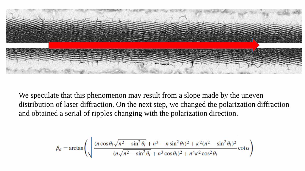
We speculate that this phenomenon may result from a slope made by the uneven
distribution of laser diffraction. On the next step, we changed the polarization diffraction
and obtained a serial of ripples changing with the polarization direction.
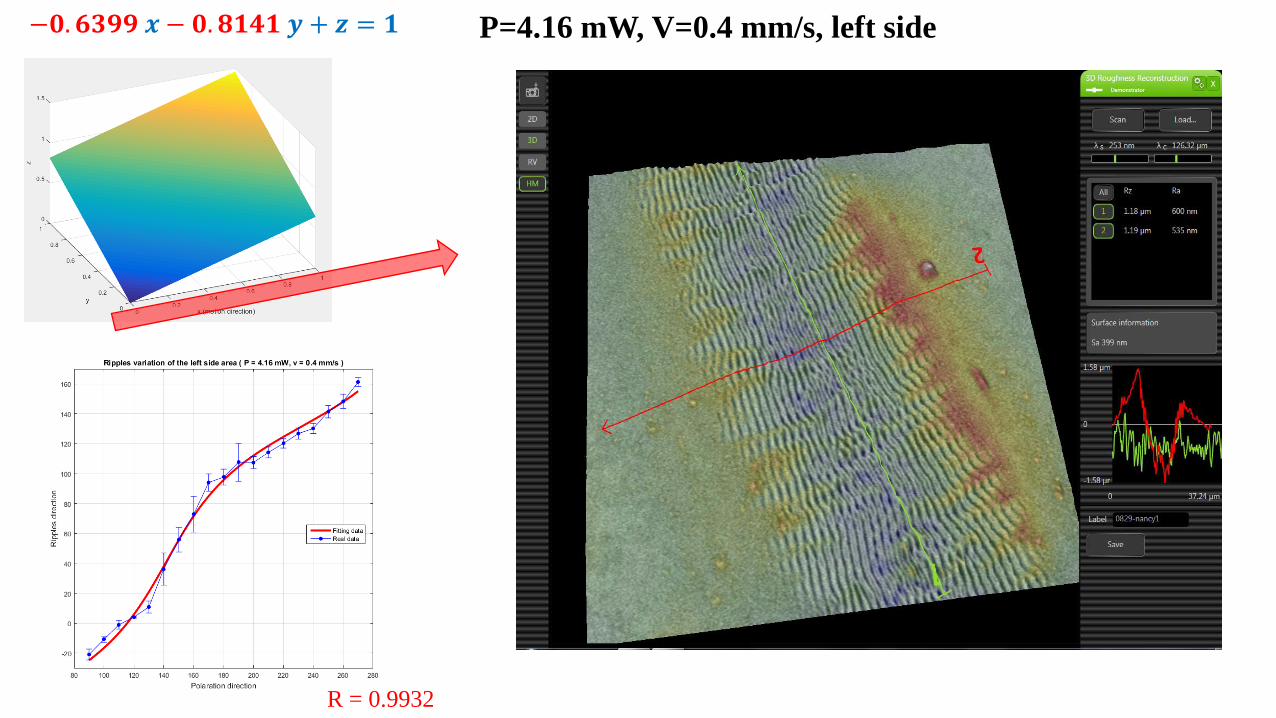
−𝟎. 𝟔𝟑𝟗𝟗 𝒙 − 𝟎. 𝟖𝟏𝟒𝟏 𝒚 + 𝒛 = 𝟏 P=4.16 mW, V=0.4 mm/s, left side
R = 0.9932

(b) Ripples Recognizer

Let me introduce the setting one by one.
The main principle of this software is to use 2-dimensional fast Fourier transformation to obtain information from the
pictures. There are many other filter methods added, making the result more accurate and defensible.
As for analyses this following picture.
The interval range can be estimated from 3 pixels to 20 pixels and the angle of
the ripples can be easily described from 30 degree to 90 degree. By these
information, we can accurately acquire the average information.
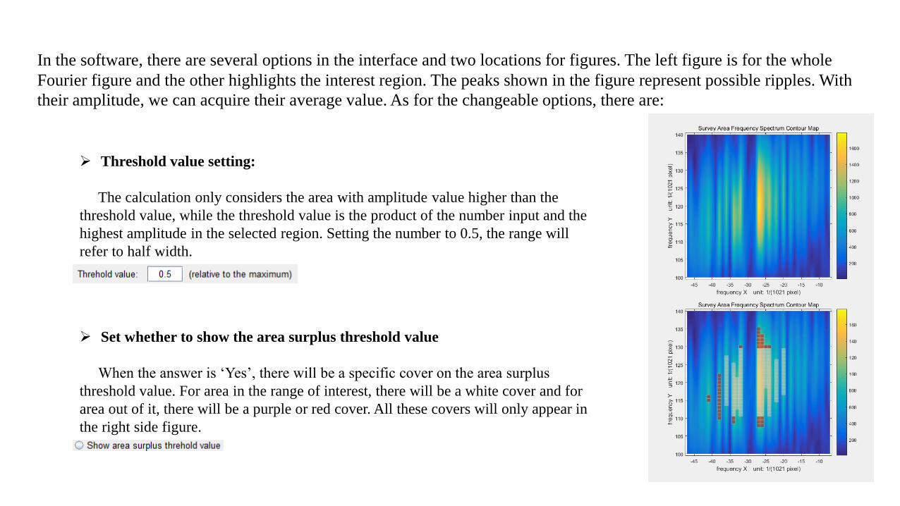
In the software, there are several options in the interface and two locations for figures. The left figure is for the whole
Fourier figure and the other highlights the interest region. The peaks shown in the figure represent possible ripples. With
their amplitude, we can acquire their average value. As for the changeable options, there are:
Set whether to show the area surplus threshold value
When the answer is ‘Yes’, there will be a specific cover on the area surplus
threshold value. For area in the range of interest, there will be a white cover and for
area out of it, there will be a purple or red cover. All these covers will only appear in
the right side figure.
Threshold value setting:
The calculation only considers the area with amplitude value higher than the
threshold value, while the threshold value is the product of the number input and the
highest amplitude in the selected region. Setting the number to 0.5, the range will
refer to half width.

Base frequency elimination setting on coordinate axis:
There are usually some base frequency on the coordinate axis, this setting can help to eliminate them and use the value around
them to have it smoothing.
Set whether to show the sublines:
To make it convenient for users to use, we give this option to users to choose whether to show the sublines or not. The sublines
emphasizes the area selected by the choose of angles and intervals.
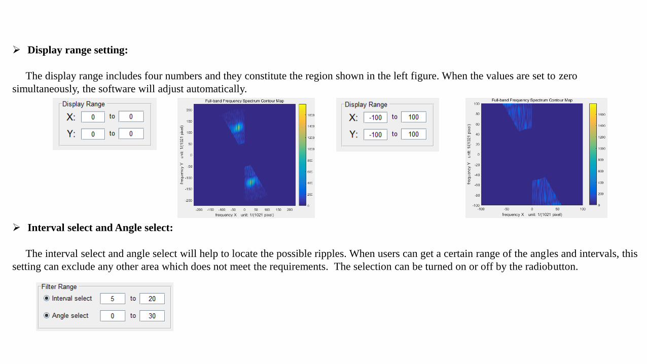
Display range setting:
The display range includes four numbers and they constitute the region shown in the left figure. When the values are set to zero
simultaneously, the software will adjust automatically.
Interval select and Angle select:
The interval select and angle select will help to locate the possible ripples. When users can get a certain range of the angles and intervals, this
setting can exclude any other area which does not meet the requirements. The selection can be turned on or off by the radiobutton.

Interval select and angle select:
These are some instances about how the selections work.

Peak range setting:
The peak range setting will help to locate a region. By adjusting the numbers, the range will be changed and only the values in the range can
be used to calculate the final result.

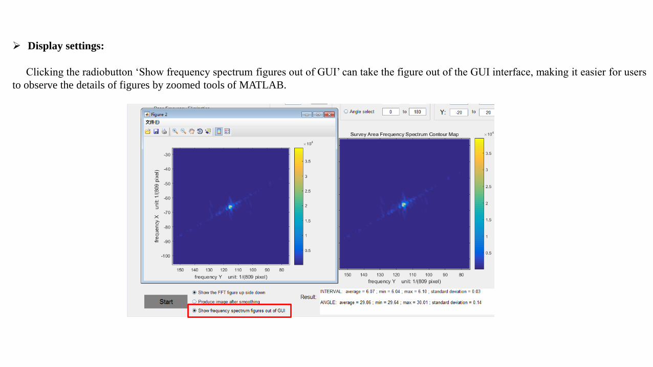
Display settings:
Clicking the radiobutton ‘Show the FFT figure upside down’ can change the direction of coordinate axes, which can set the direction of the
peak point equal to the direction of the ripples. This way adjusting the angle selection will become quite convenient and visual.
Display settings:
Clicking the radiobutton ‘Show frequency spectrum figures out of GUI’ can take the figure out of the GUI interface, making it easier for users
to observe the details of figures by zoomed tools of MATLAB.

Smoothing settings:
Clicking the radiobutton ‘Produce image after smoothing’ can provide a new picture based on the angle selection and interval selection, which
can be used to remove noise. In an image with more than one directions, users can choose a certain direction and eliminate the others.
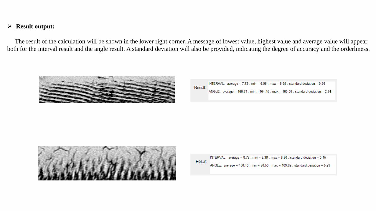
Result output:
The result of the calculation will be shown in the lower right corner. A message of lowest value, highest value and average value will appear
both for the interval result and the angle result. A standard deviation will also be provided, indicating the degree of accuracy and the orderliness.

This software can help users to find information in pictures more easily and to deal with FFT image more intuitively.


(c) Motion controller


This software can help to synchronize several equipment and help to organize them
to work together. And can read a special program to let the laser fabrication system
run automatically.