Embed Size (px)
Citation preview
8/3/2019 Report on Ccna
http://slidepdf.com/reader/full/report-on-ccna 1/59
NETWORK
In information technology, a network is a series of points or nodes interconnected bycommunication paths. Networks can interconnect with other networks and contain
subnetworks.
Requirements for creating a network:-
1. What is Network Cable?
Cable is the medium through which information usually moves from one network device
to another. There are several types of cable which are commonly used with LANs. Insome cases, a network will utilize only one type of cable, other networks will use a
variety of cable types. The type of cable chosen for a network is related to the network's
topology, protocol, and size. Understanding the characteristics of different types of cableand how they relate to other aspects of a network is necessary for the development of a
successful network.
The following sections discuss the types of cables used in networks and other related
topics.
• Unshielded Twisted Pair (UTP) Cable• Shielded Twisted Pair (STP) Cable
• Coaxial Cable
• Fiber Optic Cable
• Cable Installation Guides
• Wireless LANs
Unshielded Twisted Pair (UTP) Cable
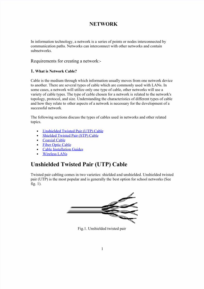
Twisted pair cabling comes in two varieties: shielded and unshielded. Unshielded twisted pair (UTP) is the most popular and is generally the best option for school networks (See
fig. 1).
Fig.1. Unshielded twisted pair
1
8/3/2019 Report on Ccna
http://slidepdf.com/reader/full/report-on-ccna 2/59
The quality of UTP may vary from telephone-grade wire to extremely high-speed cable.
The cable has four pairs of wires inside the jacket. Each pair is twisted with a differentnumber of twists per inch to help eliminate interference from adjacent pairs and other
electrical devices. The tighter the twisting, the higher the supported transmission rate and
the greater the cost per foot.
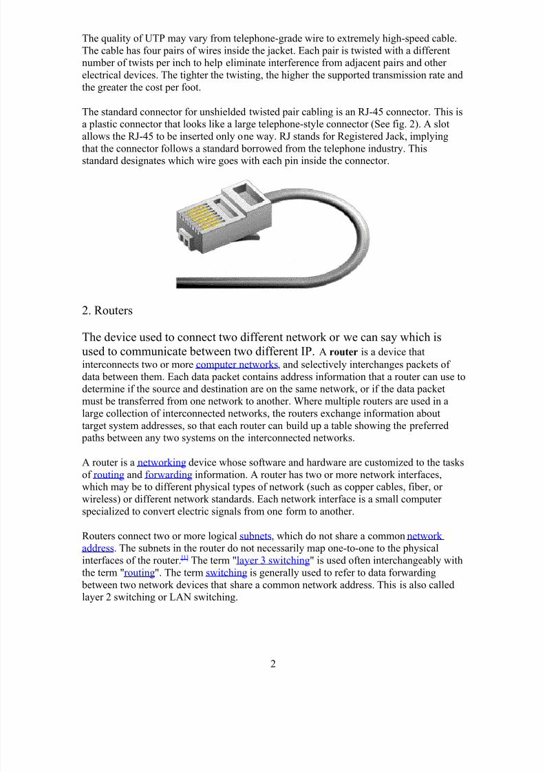
The standard connector for unshielded twisted pair cabling is an RJ-45 connector. This isa plastic connector that looks like a large telephone-style connector (See fig. 2). A slot
allows the RJ-45 to be inserted only one way. RJ stands for Registered Jack, implyingthat the connector follows a standard borrowed from the telephone industry. Thisstandard designates which wire goes with each pin inside the connector.
2. Routers
The device used to connect two different network or we can say which is
used to communicate between two different IP. A router is a device that
interconnects two or more computer networks, and selectively interchanges packets of
data between them. Each data packet contains address information that a router can use todetermine if the source and destination are on the same network, or if the data packet
must be transferred from one network to another. Where multiple routers are used in alarge collection of interconnected networks, the routers exchange information about
target system addresses, so that each router can build up a table showing the preferred paths between any two systems on the interconnected networks.
A router is a networking device whose software and hardware are customized to the tasks
of routing and forwarding information. A router has two or more network interfaces,which may be to different physical types of network (such as copper cables, fiber, or
wireless) or different network standards. Each network interface is a small computer
specialized to convert electric signals from one form to another.
Routers connect two or more logical subnets, which do not share a common network address. The subnets in the router do not necessarily map one-to-one to the physical
interfaces of the router.[1] The term "layer 3 switching" is used often interchangeably with
the term "routing". The term switching is generally used to refer to data forwarding
between two network devices that share a common network address. This is also calledlayer 2 switching or LAN switching.
2
8/3/2019 Report on Ccna
http://slidepdf.com/reader/full/report-on-ccna 3/59
IP address: it is a unique identification no. that is used identify a particular
computers
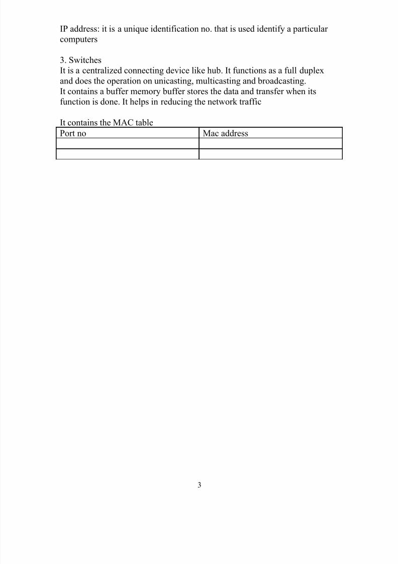
3. Switches
It is a centralized connecting device like hub. It functions as a full duplex
and does the operation on unicasting, multicasting and broadcasting.
It contains a buffer memory buffer stores the data and transfer when its
function is done. It helps in reducing the network traffic
It contains the MAC table
Port no Mac address
3
8/3/2019 Report on Ccna
http://slidepdf.com/reader/full/report-on-ccna 4/59
Network Topologies
Topology - Physical and logical network
layoutPhysical – actual layout of the computer cables
and other network devices
Logical – the way in which the network appearsto the devices that use it.
Common topologies:Bus, ring, star, mesh and wireless
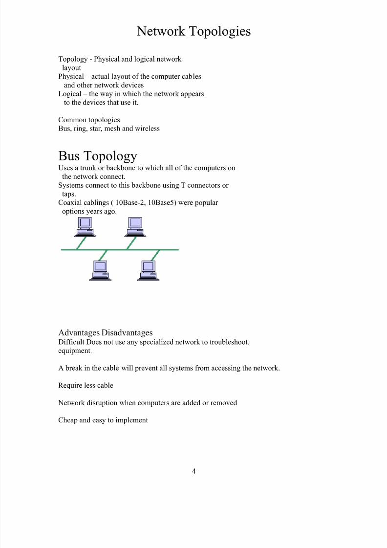
Bus TopologyUses a trunk or backbone to which all of the computers on
the network connect.
Systems connect to this backbone using T connectors or
taps.Coaxial cablings ( 10Base-2, 10Base5) were popular
options years ago.
Advantages DisadvantagesDifficult Does not use any specialized network to troubleshoot.equipment.
A break in the cable will prevent all systems from accessing the network.
Require less cable
Network disruption when computers are added or removed
Cheap and easy to implement
4
8/3/2019 Report on Ccna
http://slidepdf.com/reader/full/report-on-ccna 5/59
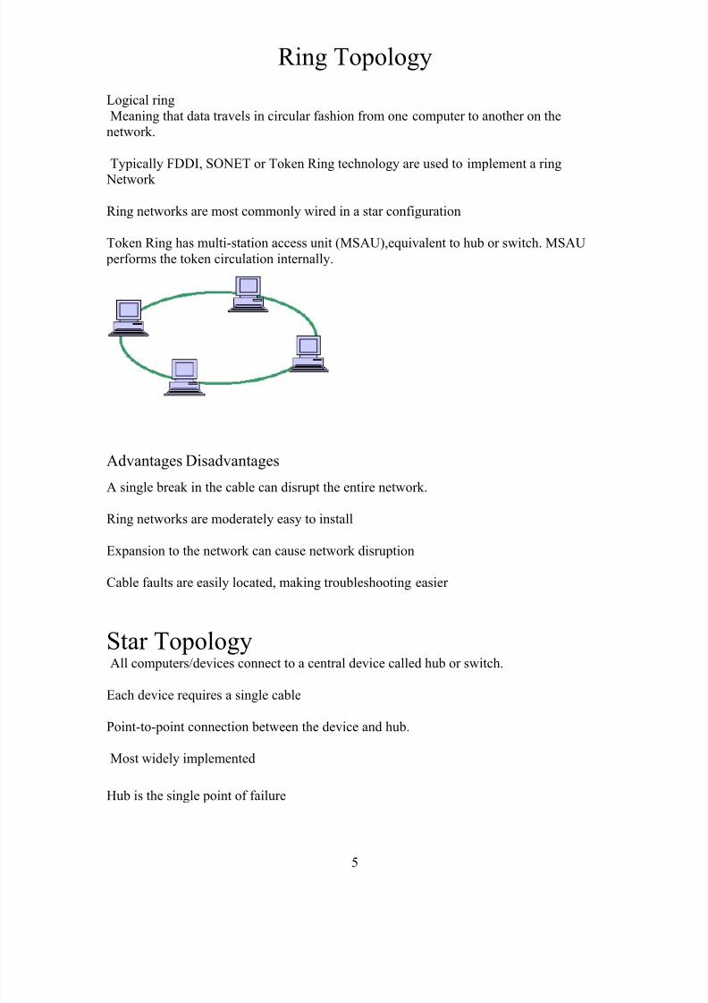
Ring Topology
Logical ring
Meaning that data travels in circular fashion from one computer to another on thenetwork.
Typically FDDI, SONET or Token Ring technology are used to implement a ring
Network
Ring networks are most commonly wired in a star configuration
Token Ring has multi-station access unit (MSAU),equivalent to hub or switch. MSAU
performs the token circulation internally.
Advantages Disadvantages
A single break in the cable can disrupt the entire network.
Ring networks are moderately easy to install
Expansion to the network can cause network disruption
Cable faults are easily located, making troubleshooting easier
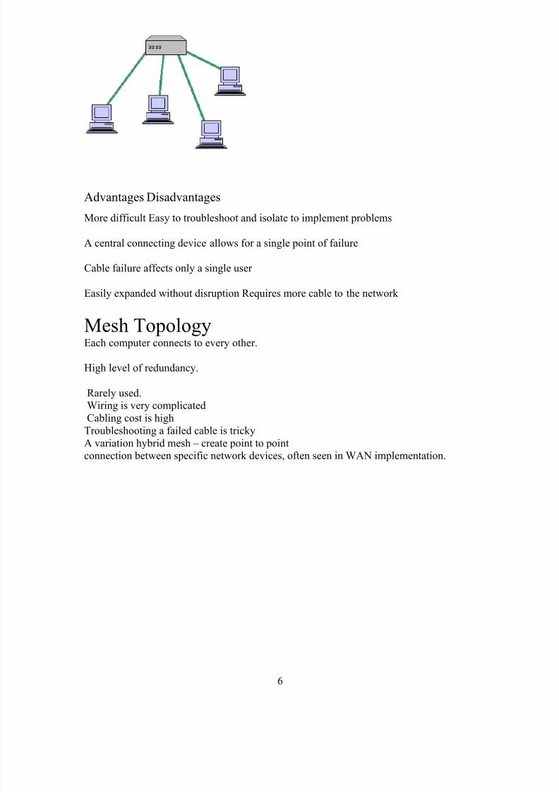
Star TopologyAll computers/devices connect to a central device called hub or switch.
Each device requires a single cable
Point-to-point connection between the device and hub.
Most widely implemented
Hub is the single point of failure
5
8/3/2019 Report on Ccna
http://slidepdf.com/reader/full/report-on-ccna 6/59
Advantages Disadvantages
More difficult Easy to troubleshoot and isolate to implement problems
A central connecting device allows for a single point of failure
Cable failure affects only a single user
Easily expanded without disruption Requires more cable to the network
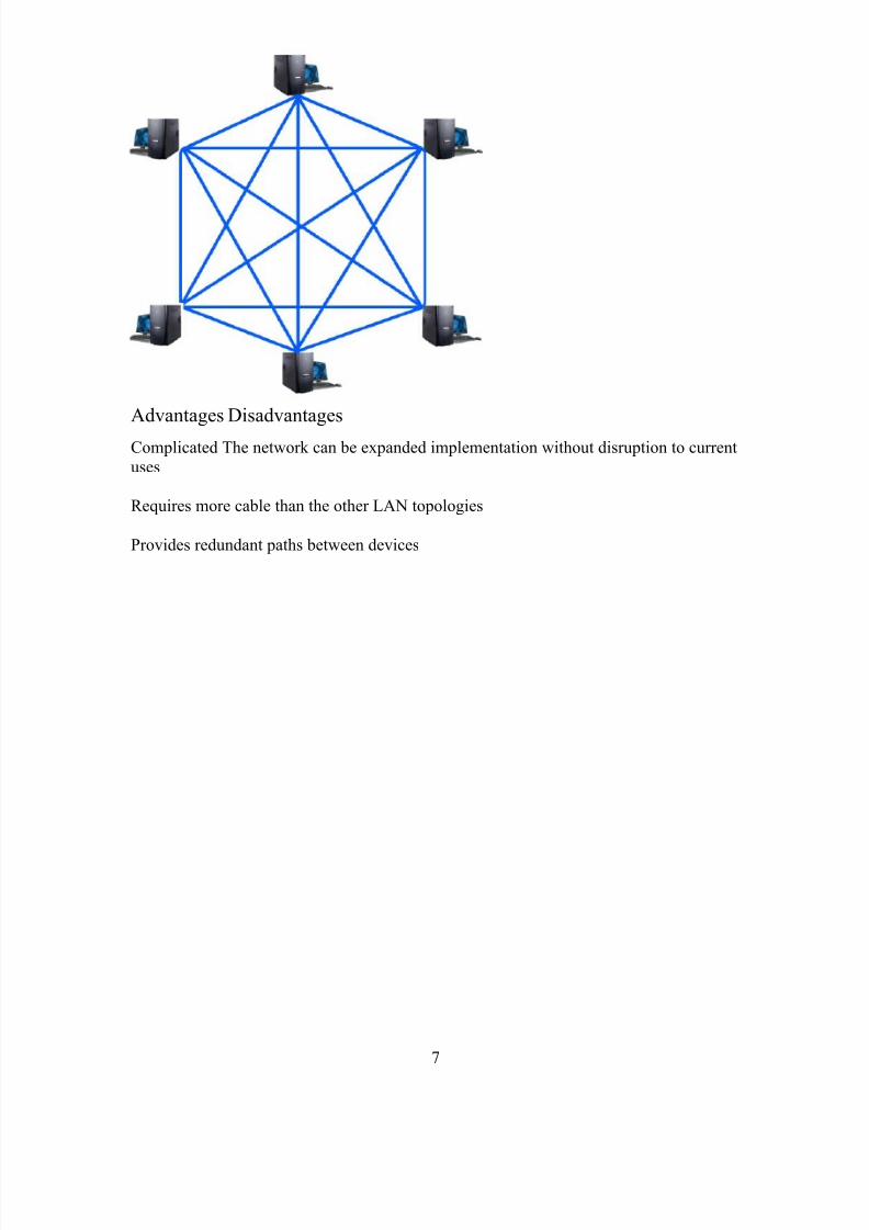
Mesh TopologyEach computer connects to every other.
High level of redundancy.
Rarely used.Wiring is very complicated
Cabling cost is highTroubleshooting a failed cable is tricky
A variation hybrid mesh – create point to pointconnection between specific network devices, often seen in WAN implementation.
6
8/3/2019 Report on Ccna
http://slidepdf.com/reader/full/report-on-ccna 7/59
Advantages Disadvantages
Complicated The network can be expanded implementation without disruption to current
uses
Requires more cable than the other LAN topologies
Provides redundant paths between devices
7
8/3/2019 Report on Ccna
http://slidepdf.com/reader/full/report-on-ccna 8/59
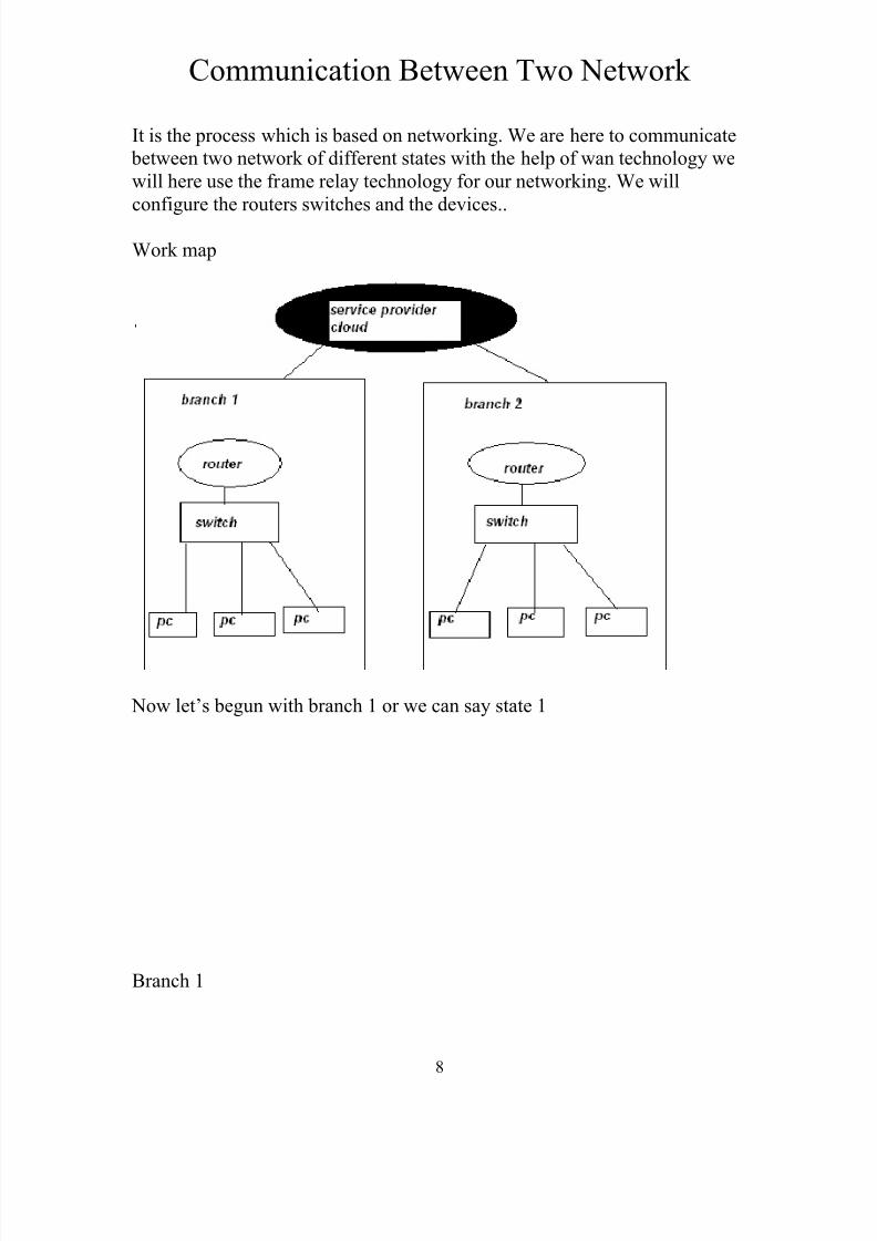
Communication Between Two Network
It is the process which is based on networking. We are here to communicate
between two network of different states with the help of wan technology we
will here use the frame relay technology for our networking. We will
configure the routers switches and the devices..
Work map
Now let’s begun with branch 1 or we can say state 1
Branch 1
8
8/3/2019 Report on Ccna
http://slidepdf.com/reader/full/report-on-ccna 9/59
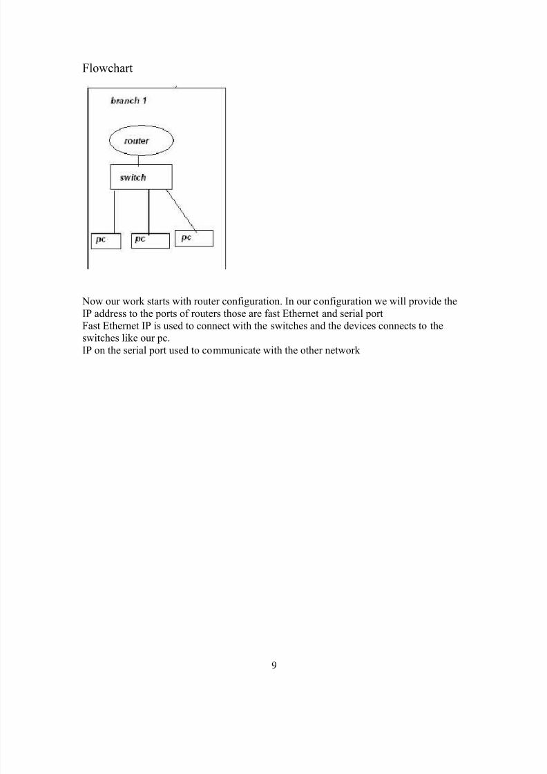
Flowchart
Now our work starts with router configuration. In our configuration we will provide the
IP address to the ports of routers those are fast Ethernet and serial port
Fast Ethernet IP is used to connect with the switches and the devices connects to theswitches like our pc.
IP on the serial port used to communicate with the other network
9
8/3/2019 Report on Ccna
http://slidepdf.com/reader/full/report-on-ccna 10/59
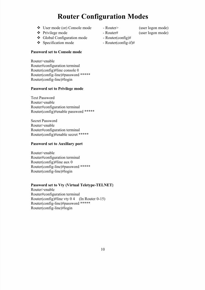
Router Configuration Modes
User mode (or) Console mode - Router> (user logon mode)
Privilege mode - Router# (user logon mode)
Global Configuration mode - Router(config)#
Specification mode - Router(config-if)#
Password set to Console mode
Router>enable
Router#configuration terminalRouter(config)#line console 0
Router(config-line)#password *****
Router(config-line)#login
Password set to Privilege mode
Text Password
Router>enableRouter#configuration terminalRouter(config)#enable password *****
Secret Password
Router>enableRouter#configuration terminal
Router(config)#enable secret *****
Password set to Auxiliary port
Router>enableRouter#configuration terminal
Router(config)#line aux 0
Router(config-line)#password *****
Router(config-line)#login
Password set to Vty (Virtual Teletype-TELNET)
Router>enable
Router#configuration terminal
Router(config)#line vty 0 4 (In Router 0-15)
Router(config-line)#password *****Router(config-line)#login
10
8/3/2019 Report on Ccna
http://slidepdf.com/reader/full/report-on-ccna 11/59
Configure IP address to LAN port
Router>enable
Router#configuration terminalRouter(config)#interface Fastethernet 0/0
Router(config-if)#ip address ***.***.***.***. ***.***.***.***
Router(config-if)#no shutdown
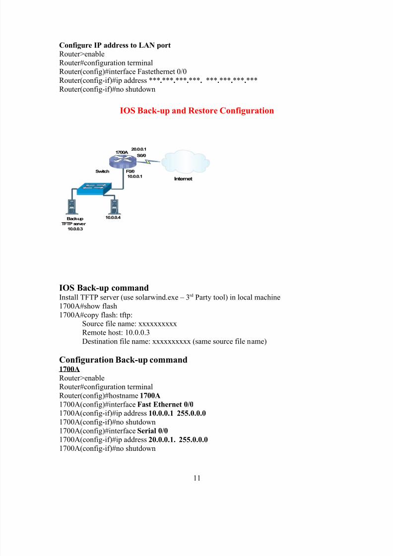
IOS Back-up and Restore Configuration
Internet
S0/0
F0/0Switch
Back-up
TFTP server
10.0.0.3
10.0.0.4
20.0.0.11700A
10.0.0.1
IOS Back-up commandInstall TFTP server (use solarwind.exe – 3rd Party tool) in local machine
1700A#show flash
1700A#copy flash: tftp:Source file name: xxxxxxxxxx
Remote host: 10.0.0.3
Destination file name: xxxxxxxxxx (same source file name)
Configuration Back-up command1700A
Router>enable
Router#configuration terminalRouter(config)#hostname 1700A
1700A(config)#interface Fast Ethernet 0/0
1700A(config-if)#ip address 10.0.0.1 255.0.0.0
1700A(config-if)#no shutdown
1700A(config)#interface Serial 0/0
1700A(config-if)#ip address 20.0.0.1. 255.0.0.0
1700A(config-if)#no shutdown
11
8/3/2019 Report on Ccna
http://slidepdf.com/reader/full/report-on-ccna 12/59
1700A(config-if)#exit
1700A(config)#router rip1700A(config-router)#network 10.0.0.0
1700A(config-router)#network 20.0.0.0
1700A(config-router)#control Z1700A#show ip route
1700A#show ip interface brief
1700A#copy running configuration startup configuration
1700A#copy startup configuration tftp:10.0.0.3
File name: AAAAt
Erase Starting configuration command1700A#erase startup configuration
Restore IOS configuration commaneIf we are already erase the starting configuration. So router doesn’t boot from
flash rom because of to change the RX Boot mode.Router>en
Router#config t
Router(config)#config-register 0X2101Router(config)#exit
Router#reload
Few second to reload…………
Router(config)#interface F0/0
Router(config-if)#ip address 10.0.0.1 255.0.0.0
Router(config-if)#no shutdownRouter(config-if)#^Z
Router#ping 10.0.0.3
Router#copy tftp: flash:
Host: 10.0.0.3
Source file name: xxxxxxxxxxSame name to transfer: xxxxxxxxxx
erase :yes
Configuration restores commandRouter#copy tftp: startup configuration
Source address: 10.0.0.3
Source file name: AAAA
Change Normal mode commandRouter(config)#config-register 0X2102Router#reload
12
8/3/2019 Report on Ccna
http://slidepdf.com/reader/full/report-on-ccna 13/59
Password Recovery Configuration
Router>enRouter#config t
Router(config)#line console 0
Router(config-line)#password 123
Router(config-line)#login
Password recovery steps
Switch off our Router then on
Press Control+Break Rommon 1 >confreg 0X2142 (to by pass the NVRAM)
Rommon 2 >reset
Would u like to default configuration ? NoRouter#show running configuration
Router#show startup configuration
To see a PasswordRouter#show ver Router#config t
Router(config)#config-register 0X2102
Router(config)#exitRouter#reload
13
8/3/2019 Report on Ccna
http://slidepdf.com/reader/full/report-on-ccna 14/59
DHCP (dynamic host configuration protocol)
It is a service that is used to provide the automatic IP address to the computer
The Dynamic Host Configuration Protocol (DHCP) is a computer networking protocolused by hosts ( DHCP clients) to retrieve IP address assignments and other configurationinformation.
DHCP uses a client-server architecture. The client sends a broadcast request for
configuration information. The DHCP server receives the request and responds with
configuration information from its configuration database.
In the absence of DHCP, all hosts on a network must be manually configuredindividually - a time-consuming and often error-prone undertaking.
DHCP is popular with ISP's because it allows a host to obtain a temporary IP address.
Way to implement it
Router(config)#ip dhcp pool 10.0.0.0/8
Router(dhcp-config)#network 10.0.0.0 255.0.0.0
Router(dhcp-config)#default-router 10.0.0.1
Router(dhcp-config)#^Z
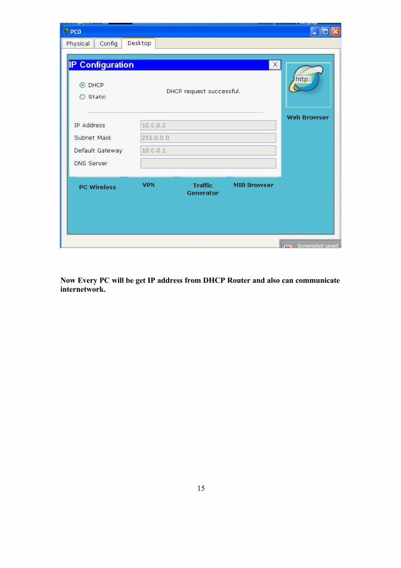
Go to all computers and set TCP/IP configuration as obtain IP automatically (DHCP)
As We are displaying in virtual is in this image.
14
8/3/2019 Report on Ccna
http://slidepdf.com/reader/full/report-on-ccna 15/59
Now Every PC will be get IP address from DHCP Router and also can communicate
internetwork.
15
8/3/2019 Report on Ccna
http://slidepdf.com/reader/full/report-on-ccna 16/59
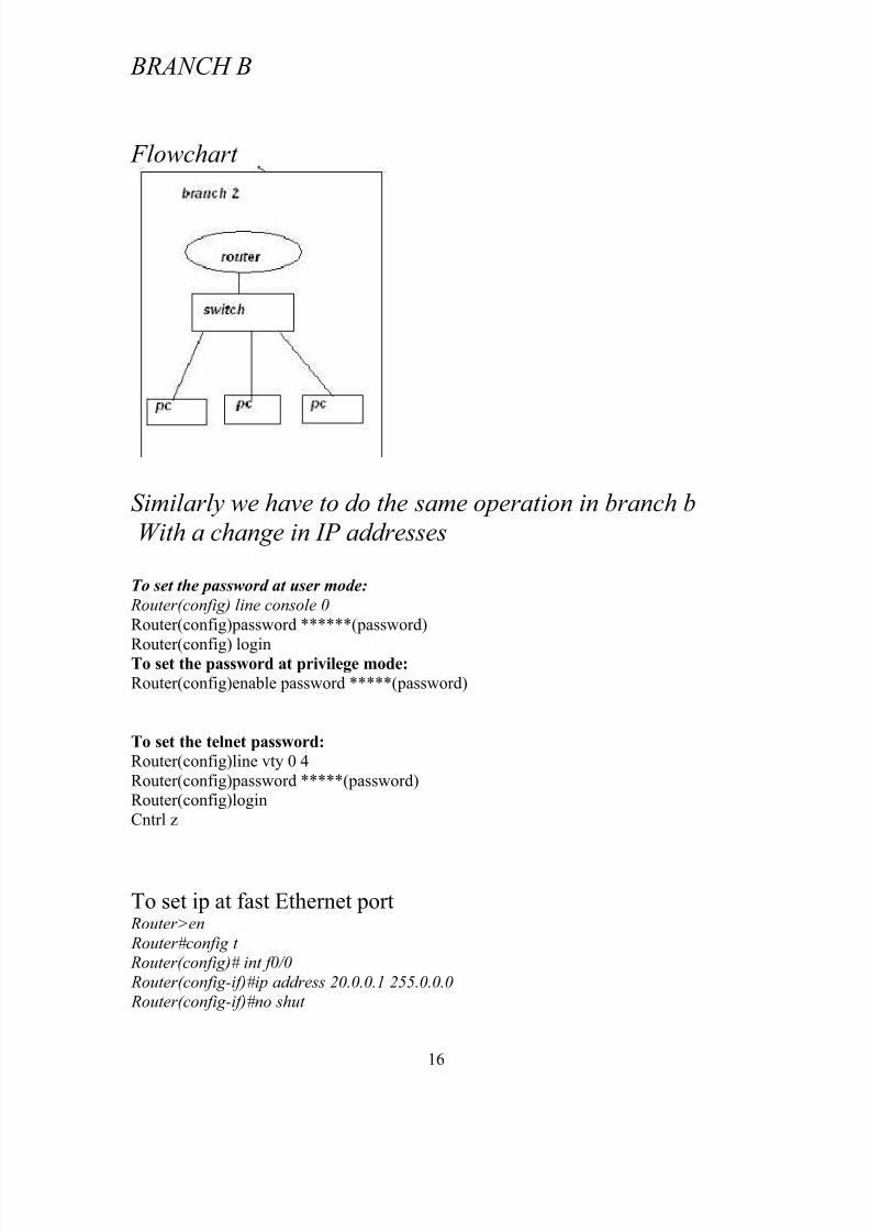
BRANCH B
Flowchart
Similarly we have to do the same operation in branch b
With a change in IP addresses
To set the password at user mode:
Router(config) line console 0
Router(config)password ******(password)
Router(config) loginTo set the password at privilege mode:
Router(config)enable password *****(password)
To set the telnet password:
Router(config)line vty 0 4
Router(config)password *****(password)Router(config)login
Cntrl z
To set ip at fast Ethernet port Router>en
Router#config t Router(config)# int f0/0
Router(config-if)#ip address 20.0.0.1 255.0.0.0
Router(config-if)#no shut
16
8/3/2019 Report on Ccna
http://slidepdf.com/reader/full/report-on-ccna 17/59
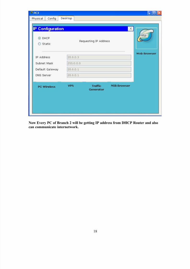
DHCP (dynamic host configuration protocol)It is a service that is used to provide the automatic IP address to the computer
The Dynamic Host Configuration Protocol (DHCP) is a computer networking protocol
used by hosts ( DHCP clients) to retrieve IP address assignments and other configurationinformation.
DHCP uses a client-server architecture. The client sends a broadcast request for
configuration information. The DHCP server receives the request and responds with
configuration information from its configuration database.
In the absence of DHCP, all hosts on a network must be manually configuredindividually - a time-consuming and often error-prone undertaking.
DHCP is popular with ISP's because it allows a host to obtain a temporary IP address.
Way to implement it
Router(config)#ip dhcp pool 20.0.0.0/8
Router(dhcp-config)#network 20.0.0.0 255.0.0.0
Router(dhcp-config)#default-router 10.0.0.1
17
8/3/2019 Report on Ccna
http://slidepdf.com/reader/full/report-on-ccna 18/59
Now Every PC of Branch 2 will be getting IP address from DHCP Router and also
can communicate internetwork.
18
8/3/2019 Report on Ccna
http://slidepdf.com/reader/full/report-on-ccna 19/59
WAN Technology
A WAN is a data communications network that covers a relatively broad geographic area
and that often uses transmission facilities provided by common carriers, such as
telephone companies. WAN technologies generally function at the lower three layers of the OSI reference model: the physical layer, the data link layer, and the network layer.
Figure 3-1 illustrates the relationship between the common WAN technologies and theOSI model.
Figure 3-1 WAN Technologies Operate at the Lowest Levels of the OSI Model
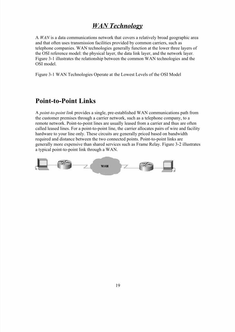
Point-to-Point Links
A point-to-point link provides a single, pre-established WAN communications path from
the customer premises through a carrier network, such as a telephone company, to aremote network. Point-to-point lines are usually leased from a carrier and thus are oftencalled leased lines. For a point-to-point line, the carrier allocates pairs of wire and facility
hardware to your line only. These circuits are generally priced based on bandwidth
required and distance between the two connected points. Point-to-point links aregenerally more expensive than shared services such as Frame Relay. Figure 3-2 illustrates
a typical point-to-point link through a WAN.
19
8/3/2019 Report on Ccna
http://slidepdf.com/reader/full/report-on-ccna 20/59
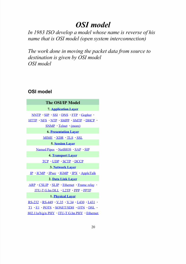
OSI model In 1983 ISO develop a model whose name is reverse of hisname that is OSI model (open system interconnection)
The work done in moving the packet data from source to
destination is given by OSI model OSI model
OSI model
The OSI/IP Model
7. Application Layer
NNTP · SIP · SSI · DNS · FTP · Gopher ·
HTTP · NFS · NTP · SMPP · SMTP · DHCP ·
SNMP · Telnet · (more)
6. Presentation Layer
MIME · XDR · TLS · SSL5. Session Layer
Named Pipes · NetBIOS · SAP · SIP
4. Transport Layer
TCP · UDP · SCTP · DCCP
3. Network Layer
IP · ICMP · IPsec · IGMP · IPX · AppleTalk
2. Data Link Layer
ARP · CSLIP · SLIP · Ethernet · Frame relay ·
ITU-T G.hn DLL · L2TP · PPP · PPTP
1. Physical Layer
RS-232 · RS-449 · V.35 · V.34 · I.430 · I.431 ·
T1 · E1 · POTS · SONET/SDH · OTN · DSL ·
802.11a/b/g/n PHY · ITU-T G.hn PHY · Ethernet
20
8/3/2019 Report on Ccna
http://slidepdf.com/reader/full/report-on-ccna 21/59
· USB · Bluetooth
This box: view • talk • edit
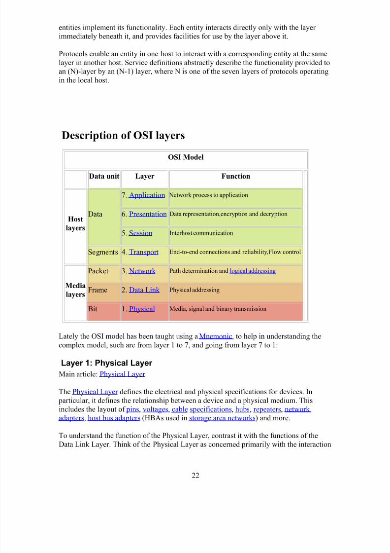
The Open Systems Interconnection model (OSI model) is a product of the OpenSystems Interconnection effort at the International Organization for Standardization. It is
a way of sub-dividing a communications system into smaller parts called layers. A layer
is a collection of conceptually similar functions that provide services to the layer above it
and receives services from the layer below it. On each layer an instance provides servicesto the instances at the layer above and requests service from the layer below.
For example, a layer that provides error-free communications, across a network providesthe path needed by applications above it, while it calls the next lower layer to send and
receive packets that make up the contents of the path. Conceptually two instances at one
layer are connected by a horizontal protocol connection on that layer.
History
In 1978, work on a layered model of network architecture was started and the
International Organization for Standardization (ISO) began to develop its OSI framework
architecture. OSI has two major components: an abstract model of networking, called the
Basic Reference Model or seven-layer model, and a set of specific protocols.
Note: The standard documents that describe the OSI model can be freely downloaded
from the ITU-T as the X.200-series of recommendations.[1] A number of the protocol
specifications are also available as part of the ITU-T X series. The equivalent ISO and
ISO/IEC standards for the OSI model are available from ISO, but only some of them atno charge.[2]
The concept of a 7 layer model was provided by the work of Charles Bachman, then of
Honeywell. Various aspects of OSI design evolved from experiences with theARPANET, the fledgling Internet, NPLNET, EIN, CYCLADES network and the work in
IFIP WG6.1. The new design was documented in ISO 7498 and its various addenda. In
this model, a networking system is divided into layers. Within each layer, one or more
21
8/3/2019 Report on Ccna
http://slidepdf.com/reader/full/report-on-ccna 22/59
entities implement its functionality. Each entity interacts directly only with the layer
immediately beneath it, and provides facilities for use by the layer above it.
Protocols enable an entity in one host to interact with a corresponding entity at the same
layer in another host. Service definitions abstractly describe the functionality provided to
an (N)-layer by an (N-1) layer, where N is one of the seven layers of protocols operating
in the local host.
Description of OSI layers
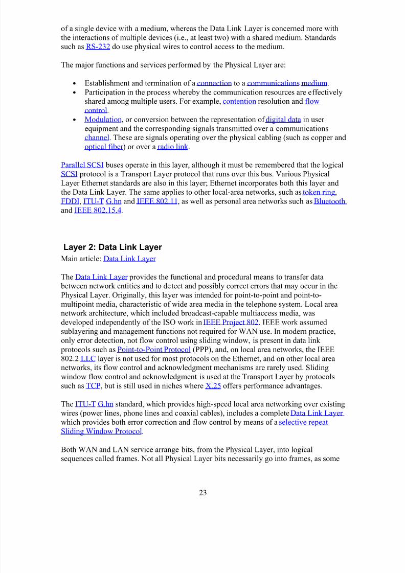
OSI Model
Data unit Layer Function
Host
layers
Data
7. Application Network process to application
6. Presentation Data representation,encryption and decryption
5. Session Interhost communication
Segments 4. Transport End-to-end connections and reliability,Flow control
Media
layers
Packet 3. Network Path determination and logical addressing
Frame 2. Data Link Physical addressing
Bit 1. Physical Media, signal and binary transmission
Lately the OSI model has been taught using a Mnemonic, to help in understanding the
complex model, such are from layer 1 to 7, and going from layer 7 to 1:
Layer 1: Physical Layer
Main article: Physical Layer
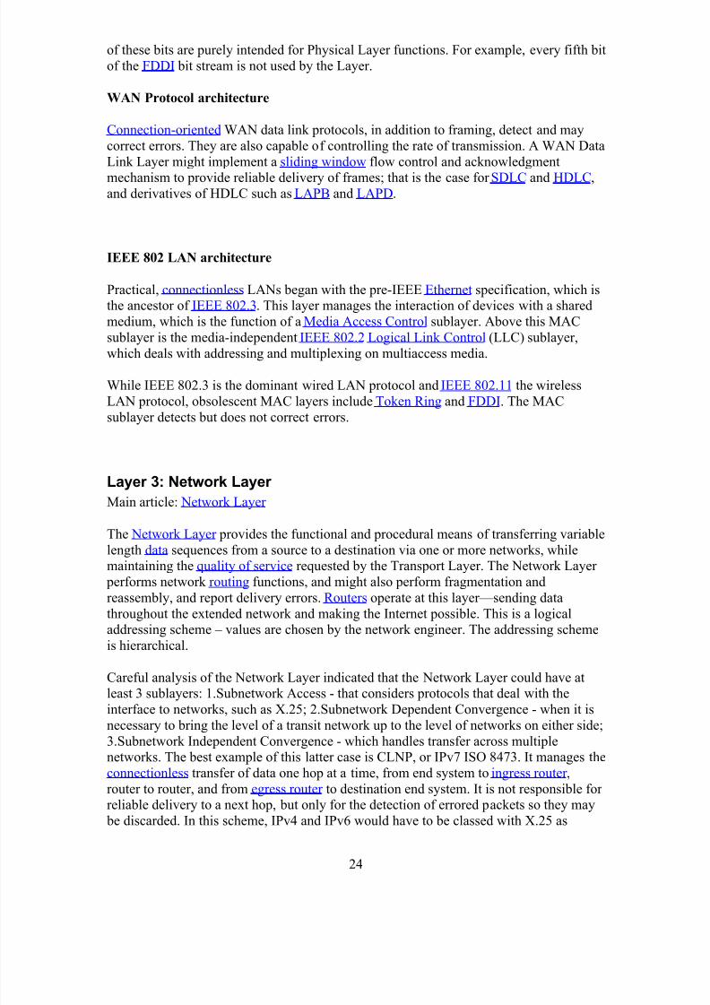
The Physical Layer defines the electrical and physical specifications for devices. In
particular, it defines the relationship between a device and a physical medium. This
includes the layout of pins, voltages, cable specifications, hubs, repeaters, network adapters, host bus adapters (HBAs used in storage area networks) and more.
To understand the function of the Physical Layer, contrast it with the functions of the
Data Link Layer. Think of the Physical Layer as concerned primarily with the interaction
22
8/3/2019 Report on Ccna
http://slidepdf.com/reader/full/report-on-ccna 23/59
of a single device with a medium, whereas the Data Link Layer is concerned more with
the interactions of multiple devices (i.e., at least two) with a shared medium. Standardssuch as RS-232 do use physical wires to control access to the medium.
The major functions and services performed by the Physical Layer are:
• Establishment and termination of a connection to a communications medium.
• Participation in the process whereby the communication resources are effectively
shared among multiple users. For example, contention resolution and flowcontrol.
• Modulation, or conversion between the representation of digital data in user
equipment and the corresponding signals transmitted over a communicationschannel. These are signals operating over the physical cabling (such as copper and
optical fiber ) or over a radio link .
Parallel SCSI buses operate in this layer, although it must be remembered that the logicalSCSI protocol is a Transport Layer protocol that runs over this bus. Various Physical
Layer Ethernet standards are also in this layer; Ethernet incorporates both this layer and
the Data Link Layer. The same applies to other local-area networks, such as token ring,
FDDI, ITU-T G.hn and IEEE 802.11, as well as personal area networks such as Bluetooth and IEEE 802.15.4.
Layer 2: Data Link Layer
Main article: Data Link Layer
The Data Link Layer provides the functional and procedural means to transfer data between network entities and to detect and possibly correct errors that may occur in the
Physical Layer. Originally, this layer was intended for point-to-point and point-to-
multipoint media, characteristic of wide area media in the telephone system. Local areanetwork architecture, which included broadcast-capable multiaccess media, was
developed independently of the ISO work in IEEE Project 802. IEEE work assumed
sublayering and management functions not required for WAN use. In modern practice,only error detection, not flow control using sliding window, is present in data link
protocols such as Point-to-Point Protocol (PPP), and, on local area networks, the IEEE
802.2 LLC layer is not used for most protocols on the Ethernet, and on other local areanetworks, its flow control and acknowledgment mechanisms are rarely used. Sliding
window flow control and acknowledgment is used at the Transport Layer by protocols
such as TCP, but is still used in niches where X.25 offers performance advantages.
The ITU-T G.hn standard, which provides high-speed local area networking over existingwires (power lines, phone lines and coaxial cables), includes a complete Data Link Layer
which provides both error correction and flow control by means of a selective repeat
Sliding Window Protocol.
Both WAN and LAN service arrange bits, from the Physical Layer, into logicalsequences called frames. Not all Physical Layer bits necessarily go into frames, as some
23
8/3/2019 Report on Ccna
http://slidepdf.com/reader/full/report-on-ccna 24/59
of these bits are purely intended for Physical Layer functions. For example, every fifth bit
of the FDDI bit stream is not used by the Layer.
WAN Protocol architecture
Connection-oriented WAN data link protocols, in addition to framing, detect and may
correct errors. They are also capable of controlling the rate of transmission. A WAN Data
Link Layer might implement a sliding window flow control and acknowledgment
mechanism to provide reliable delivery of frames; that is the case for SDLC and HDLC,and derivatives of HDLC such as LAPB and LAPD.
IEEE 802 LAN architecture
Practical, connectionless LANs began with the pre-IEEE Ethernet specification, which isthe ancestor of IEEE 802.3. This layer manages the interaction of devices with a shared
medium, which is the function of a Media Access Control sublayer. Above this MAC
sublayer is the media-independent IEEE 802.2 Logical Link Control (LLC) sublayer,
which deals with addressing and multiplexing on multiaccess media.
While IEEE 802.3 is the dominant wired LAN protocol and IEEE 802.11 the wireless
LAN protocol, obsolescent MAC layers include Token Ring and FDDI. The MAC
sublayer detects but does not correct errors.
Layer 3: Network Layer
Main article: Network Layer
The Network Layer provides the functional and procedural means of transferring variable
length data sequences from a source to a destination via one or more networks, whilemaintaining the quality of service requested by the Transport Layer. The Network Layer
performs network routing functions, and might also perform fragmentation and
reassembly, and report delivery errors. Routers operate at this layer—sending data
throughout the extended network and making the Internet possible. This is a logicaladdressing scheme – values are chosen by the network engineer. The addressing scheme
is hierarchical.
Careful analysis of the Network Layer indicated that the Network Layer could have atleast 3 sublayers: 1.Subnetwork Access - that considers protocols that deal with the
interface to networks, such as X.25; 2.Subnetwork Dependent Convergence - when it isnecessary to bring the level of a transit network up to the level of networks on either side;
3.Subnetwork Independent Convergence - which handles transfer across multiplenetworks. The best example of this latter case is CLNP, or IPv7 ISO 8473. It manages the
connectionless transfer of data one hop at a time, from end system to ingress router ,
router to router, and from egress router to destination end system. It is not responsible for reliable delivery to a next hop, but only for the detection of errored packets so they may
be discarded. In this scheme, IPv4 and IPv6 would have to be classed with X.25 as
24
8/3/2019 Report on Ccna
http://slidepdf.com/reader/full/report-on-ccna 25/59
Subnet Access protocols because they carry interface addresses rather than node
addresses.
A number of layer management protocols, a function defined in the Management Annex,
ISO 7498/4, belong to the Network Layer. These include routing protocols, multicast
group management, Network Layer information and error, and Network Layer address
assignment. It is the function of the payload that makes these belong to the Network Layer, not the protocol that carries them.
Layer 4: Transport Layer
Main article: Transport Layer
The Transport Layer provides transparent transfer of data between end users, providingreliable data transfer services to the upper layers. The Transport Layer controls the
reliability of a given link through flow control, segmentation/desegmentation, and error
control. Some protocols are state and connection oriented. This means that the TransportLayer can keep track of the segments and retransmit those that fail.
Although not developed under the OSI Reference Model and not strictly conforming to
the OSI definition of the Transport Layer, typical examples of Layer 4 are the
Transmission Control Protocol (TCP) and User Datagram Protocol (UDP).
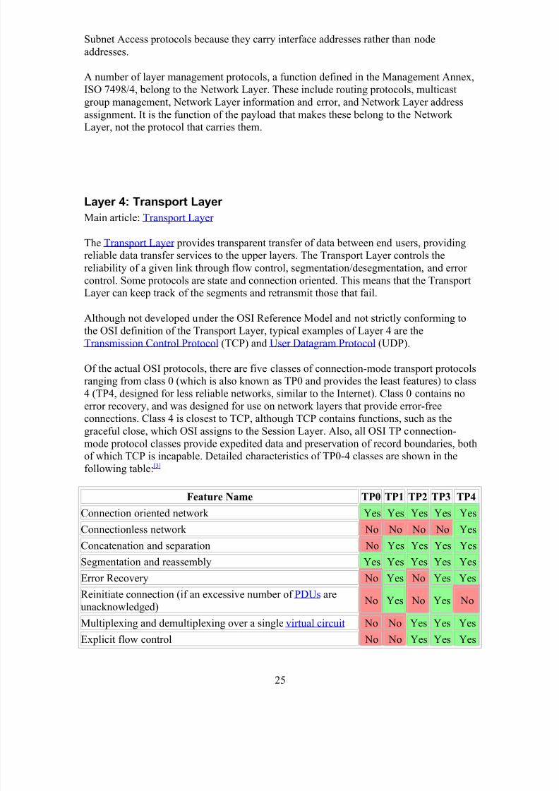
Of the actual OSI protocols, there are five classes of connection-mode transport protocolsranging from class 0 (which is also known as TP0 and provides the least features) to class
4 (TP4, designed for less reliable networks, similar to the Internet). Class 0 contains no
error recovery, and was designed for use on network layers that provide error-free
connections. Class 4 is closest to TCP, although TCP contains functions, such as thegraceful close, which OSI assigns to the Session Layer. Also, all OSI TP connection-
mode protocol classes provide expedited data and preservation of record boundaries, bothof which TCP is incapable. Detailed characteristics of TP0-4 classes are shown in the
following table:[3]
Feature Name TP0 TP1 TP2 TP3 TP4
Connection oriented network Yes Yes Yes Yes Yes
Connectionless network No No No No Yes
Concatenation and separation No Yes Yes Yes Yes
Segmentation and reassembly Yes Yes Yes Yes Yes
Error Recovery No Yes No Yes Yes
Reinitiate connection (if an excessive number of PDUs are
unacknowledged) No Yes No Yes No
Multiplexing and demultiplexing over a single virtual circuit No No Yes Yes Yes
Explicit flow control No No Yes Yes Yes
25
8/3/2019 Report on Ccna
http://slidepdf.com/reader/full/report-on-ccna 26/59
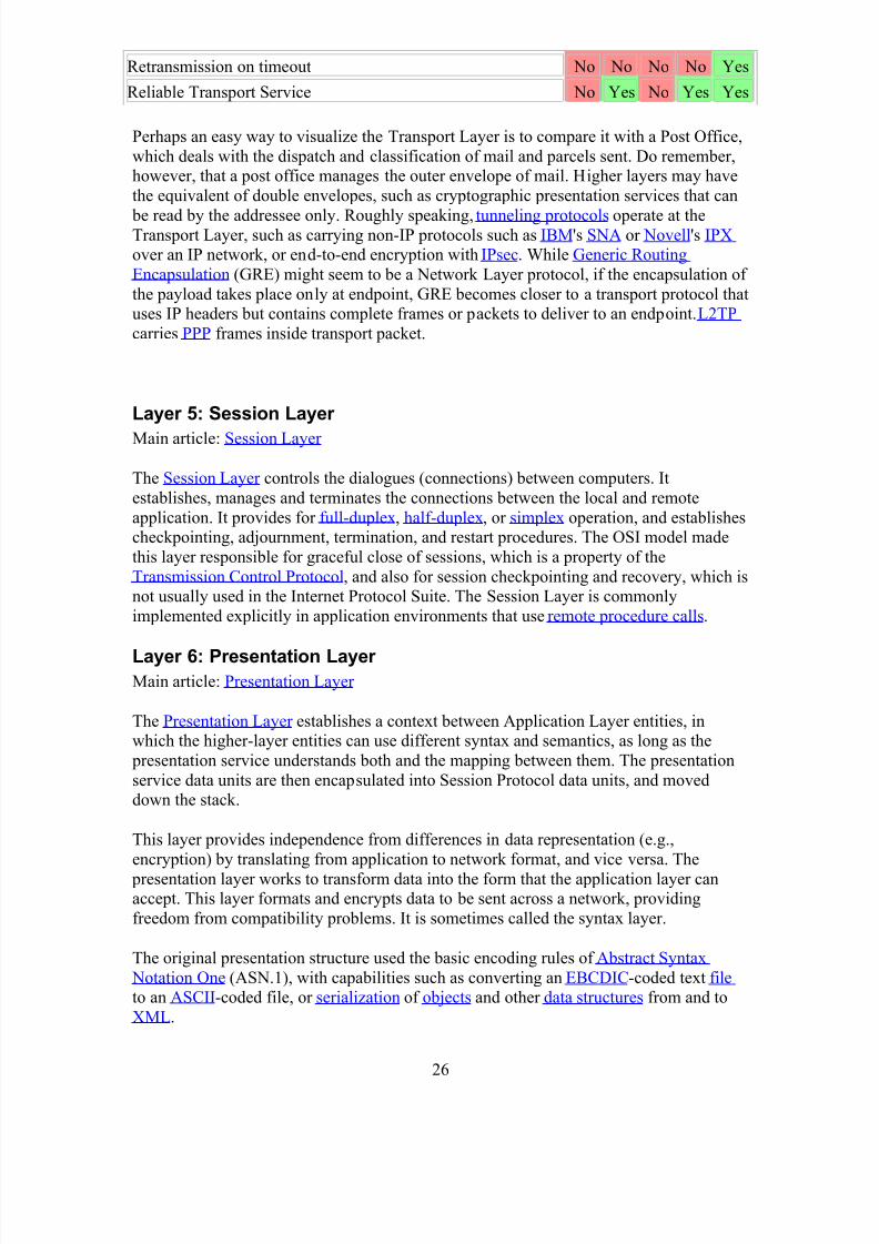
Retransmission on timeout No No No No Yes
Reliable Transport Service No Yes No Yes Yes
Perhaps an easy way to visualize the Transport Layer is to compare it with a Post Office,
which deals with the dispatch and classification of mail and parcels sent. Do remember,however, that a post office manages the outer envelope of mail. Higher layers may have
the equivalent of double envelopes, such as cryptographic presentation services that can
be read by the addressee only. Roughly speaking, tunneling protocols operate at theTransport Layer, such as carrying non-IP protocols such as IBM's SNA or Novell's IPXover an IP network, or end-to-end encryption with IPsec. While Generic Routing
Encapsulation (GRE) might seem to be a Network Layer protocol, if the encapsulation of
the payload takes place only at endpoint, GRE becomes closer to a transport protocol thatuses IP headers but contains complete frames or packets to deliver to an endpoint. L2TP
carries PPP frames inside transport packet.
Layer 5: Session Layer
Main article: Session Layer
The Session Layer controls the dialogues (connections) between computers. It
establishes, manages and terminates the connections between the local and remote
application. It provides for full-duplex, half-duplex, or simplex operation, and establishescheckpointing, adjournment, termination, and restart procedures. The OSI model made
this layer responsible for graceful close of sessions, which is a property of the
Transmission Control Protocol, and also for session checkpointing and recovery, which isnot usually used in the Internet Protocol Suite. The Session Layer is commonly
implemented explicitly in application environments that use remote procedure calls.
Layer 6: Presentation Layer Main article: Presentation Layer
The Presentation Layer establishes a context between Application Layer entities, inwhich the higher-layer entities can use different syntax and semantics, as long as the
presentation service understands both and the mapping between them. The presentation
service data units are then encapsulated into Session Protocol data units, and moveddown the stack.
This layer provides independence from differences in data representation (e.g.,
encryption) by translating from application to network format, and vice versa. The
presentation layer works to transform data into the form that the application layer canaccept. This layer formats and encrypts data to be sent across a network, providing
freedom from compatibility problems. It is sometimes called the syntax layer.
The original presentation structure used the basic encoding rules of Abstract Syntax
Notation One (ASN.1), with capabilities such as converting an EBCDIC-coded text fileto an ASCII-coded file, or serialization of objects and other data structures from and to
XML.
26
8/3/2019 Report on Ccna
http://slidepdf.com/reader/full/report-on-ccna 27/59
Layer 7: application layer
This layer supports application and end-user processes. Communication partners are identified,quality of service is identified, user authentication and privacy are considered, and anyconstraints on data syntax are identified. Everything at this layer is application-specific. This layer provides application services for file transfers, e-mail, and other network software services. Telnetand FTP are applications that exist entirely in the application level. Tiered applicationarchitectures are part of this layer.
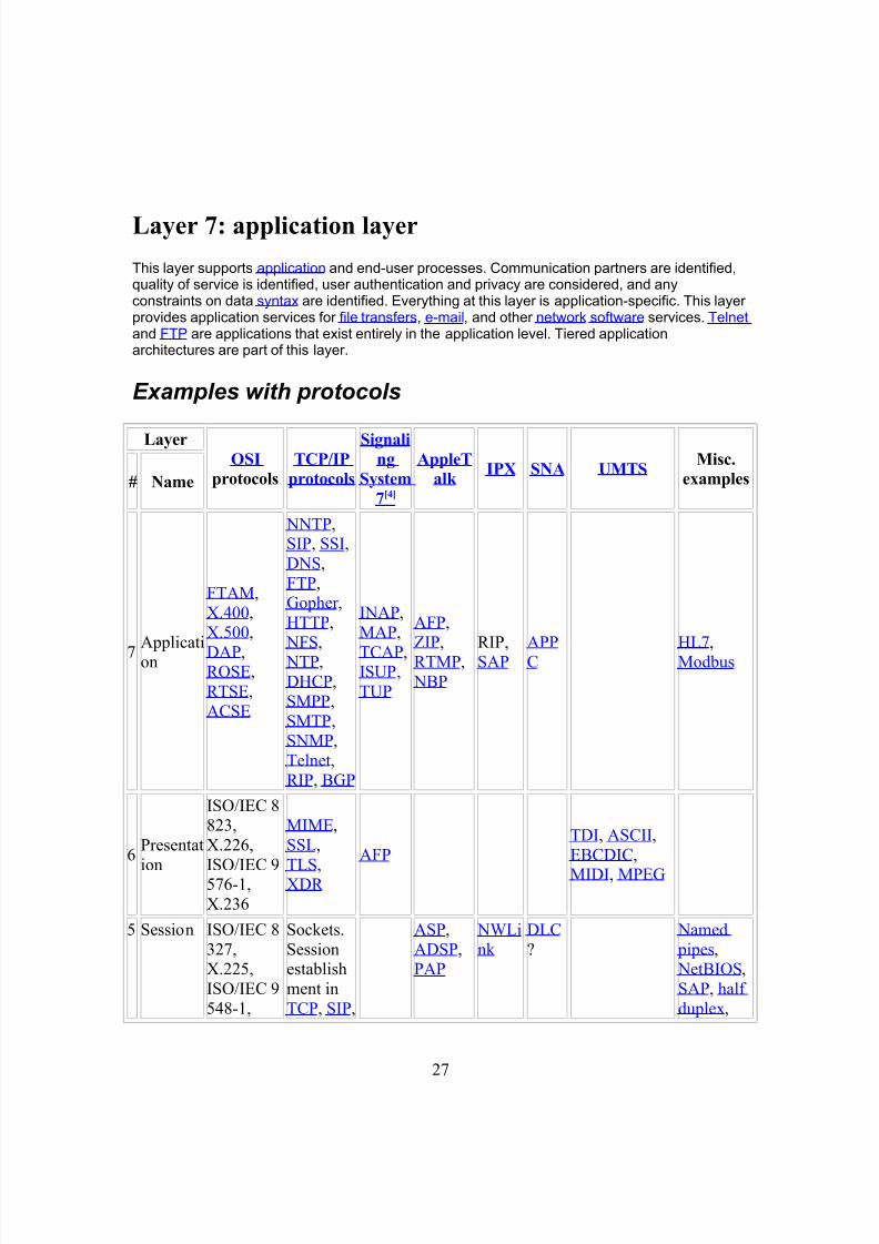
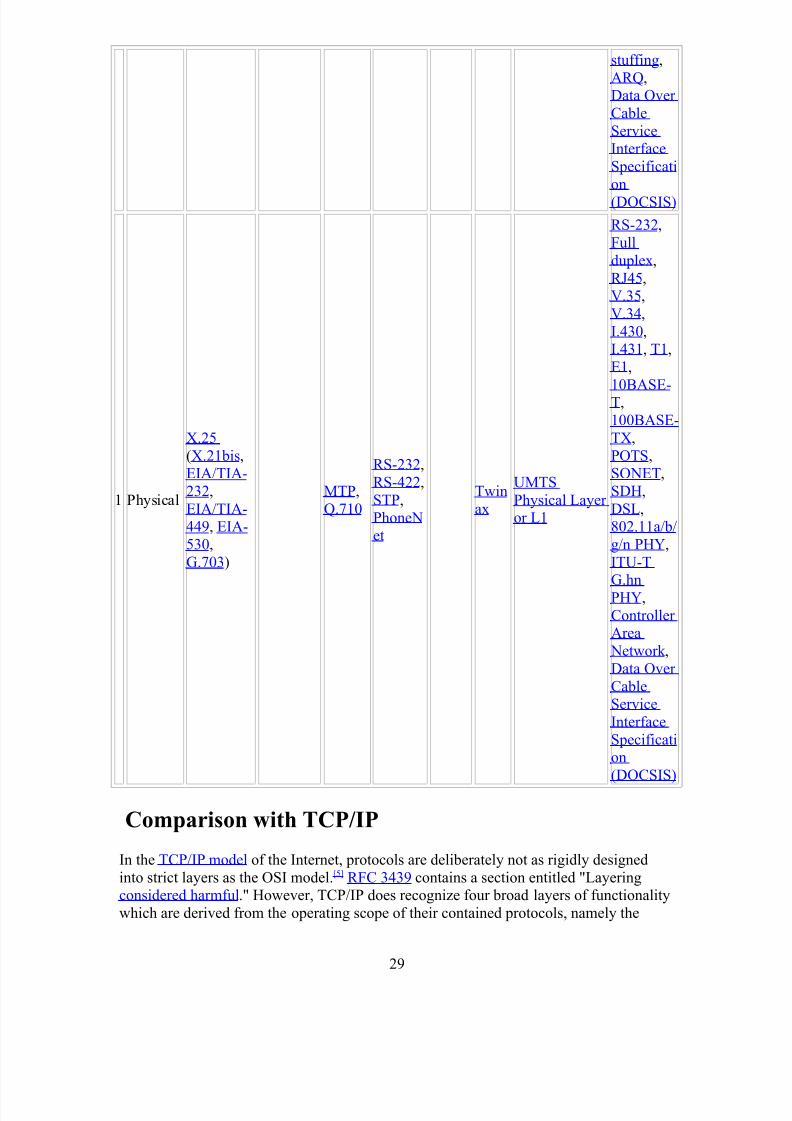
Examples with protocols
LayerOSI
protocols
TCP/IP
protocols
Signaling
System
7[4]
AppleT
alk IPX SNA UMTS
Misc.
examples# Name
7Application
FTAM,X.400,
X.500,
DAP,ROSE,
RTSE,
ACSE
NNTP,SIP, SSI,
DNS,
FTP,Gopher ,
HTTP,
NFS, NTP,
DHCP,
SMPP,
SMTP,SNMP,
Telnet,
RIP, BGP
INAP,
MAP,
TCAP,ISUP,
TUP
AFP,
ZIP,RTMP,
NBP
RIP,SAP
APPC
HL7, Modbus
6Presentat
ion
ISO/IEC 8823,
X.226,
ISO/IEC 9576-1,
X.236
MIME,
SSL,
TLS,XDR
AFP
TDI, ASCII,
EBCDIC,
MIDI, MPEG
5 Session ISO/IEC 8
327,X.225,
ISO/IEC 9
548-1,
Sockets.
Sessionestablish
ment in
TCP, SIP,
ASP,
ADSP,PAP
NWLi
nk
DLC
?
Named
pipes, NetBIOS,
SAP, half
duplex,
27
8/3/2019 Report on Ccna
http://slidepdf.com/reader/full/report-on-ccna 28/59
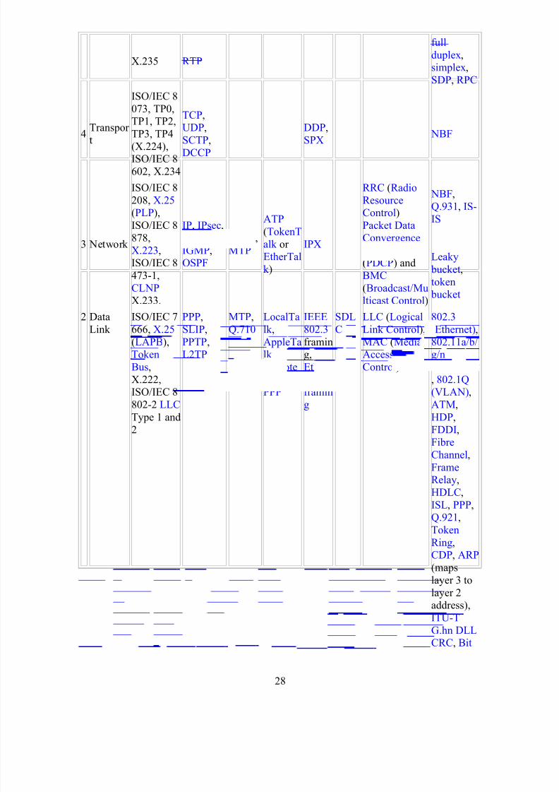
X.235 RTP
full
duplex,simplex,
SDP, RPC
4
Transpor
t
ISO/IEC 8
073, TP0,TP1, TP2,
TP3, TP4(X.224),ISO/IEC 8
602, X.234
TCP,UDP,
SCTP,DCCP
DDP,
SPX NBF
3 Network
ISO/IEC 8
208, X.25 (PLP),
ISO/IEC 8
878,
X.223,ISO/IEC 8
473-1,CLNP X.233.
IP, IPsec,
ICMP,
IGMP,OSPF
SCCP,
MTP
ATP
(TokenT
alk or EtherTal
k )
IPX
RRC (Radio
ResourceControl)
Packet Data
Convergence
Protocol (PDCP) and
BMC (Broadcast/Multicast Control)
NBF,
Q.931, IS-
IS
Leaky
bucket,
token bucket
2 Data
Link
ISO/IEC 7
666, X.25
(LAPB),Token
Bus,
X.222,ISO/IEC 8
802-2 LLC
Type 1 and2
PPP,
SLIP,
PPTP,L2TP
MTP,
Q.710
LocalTa
lk ,
AppleTalk
Remote
Access,PPP
IEEE
802.3
framing,
Ethern
et IIframin
g
SDL
C
LLC (Logical
Link Control),
MAC (MediaAccess
Control)
802.3
(Ethernet),
802.11a/b/g/n
MAC/LLC
, 802.1Q(VLAN),
ATM,
HDP, FDDI, Fibre
Channel,
FrameRelay,
HDLC,
ISL, PPP, Q.921,
Token
Ring,
CDP, ARP (maps
layer 3 to
layer 2address),
ITU-T
G.hn DLLCRC, Bit
28
8/3/2019 Report on Ccna
http://slidepdf.com/reader/full/report-on-ccna 29/59
stuffing,
ARQ,Data Over
Cable
ServiceInterface
Specificati
on
(DOCSIS)
1 Physical
X.25
(X.21bis,EIA/TIA-
232,
EIA/TIA-449, EIA-
530,
G.703)
MTP,
Q.710
RS-232,
RS-422,
STP,PhoneN
et
Twin
ax
UMTS
Physical Layer or L1
RS-232,
Full
duplex,
RJ45,V.35,
V.34,
I.430, I.431, T1,
E1,
10BASE-T,
100BASE-
TX,
POTS,SONET,
SDH,
DSL,802.11a/b/
g/n PHY,
ITU-TG.hn
PHY,
Controller Area
Network ,
Data Over
CableService
Interface
Specification
(DOCSIS)
Comparison with TCP/IP
In the TCP/IP model of the Internet, protocols are deliberately not as rigidly designed
into strict layers as the OSI model.[5] RFC 3439 contains a section entitled "Layeringconsidered harmful." However, TCP/IP does recognize four broad layers of functionality
which are derived from the operating scope of their contained protocols, namely the
29
8/3/2019 Report on Ccna
http://slidepdf.com/reader/full/report-on-ccna 30/59
scope of the software application, the end-to-end transport connection, the
internetworking range, and lastly the scope of the direct links to other nodes on the localnetwork.
Even though the concept is different from the OSI model, these layers are nevertheless
often compared with the OSI layering scheme in the following way: The Internet
Application Layer includes the OSI Application Layer, Presentation Layer, and most of the Session Layer. Its end-to-end Transport Layer includes the graceful close function of
the OSI Session Layer as well as the OSI Transport Layer. The internetworking layer (Internet Layer ) is a subset of the OSI Network Layer (see above), while the Link Layer includes the OSI Data Link and Physical Layers, as well as parts of OSI's Network Layer.
These comparisons are based on the original seven-layer protocol model as defined in
ISO 7498, rather than refinements in such things as the internal organization of the Network Layer document.
The presumably strict peer layering of the OSI model as it is usually described does not
present contradictions in TCP/IP, as it is permissible that protocol usage does not follow
the hierarchy implied in a layered model. Such examples exist in some routing protocols(e.g., OSPF), or in the description of tunneling protocols, which provide a Link Layer for
an application, although the tunnel host protocol may well be a Transport or even anApplication Layer protocol in its own right.
Wan devices:
Routers
A router is a network communication device that is used to connect two or more logicallyand physically different networks. A router can be used to connect a LAN to LAN, LAN
to WAN and LAN to internet. A router acts as a post office where sorting and
distribution of the posts (packets in case of routers) is done. A router works on the basisof an IP address. Every router has built-in operating system known as IOS. A router
works on the network layer of the OS model and it routes the data towards the optimal
path. Router uses the header information of the packets and forwarding table to definethe best shortest possible path of the data.
ISDN Adaptors
ISDN (Integrated Services Digital Network) is a data communication method and it is
used over the regular telephone lines. To use the ISDN lines, you need to install add-on
adapters known as ISDN terminal adapters. ISDN Terminal Adapter works like a digitalmodem i.e. it converts the signals from digital to analog and vice versa. ISDN Terminal
adapter is plugged into the serial port of the system. Some ISDN adapters have the
feature of switching between digital and analog modes.
30
8/3/2019 Report on Ccna
http://slidepdf.com/reader/full/report-on-ccna 31/59
CSU/DSU
CSU/DSU stands for channel service unit and data service unit. CSU is used to connect aterminal to a digital line. DSU is used to perform the protective and diagnostic functions
of the telecommunication line. CSU/DSU is a network device of the size of an external
modem. The Channel service unit receives and transmits the signals from the wide area
network line. CSU/DSU are two separate devices and they are sometimes used inconjunction with the T1 LAN cards.
Bridges
A bridge is a network communication device that is used to connect two segments of a
LAN that uses the same protocol. Bridge is like a router but it doesn’t analyze the data before sending. A bridge operates at the data link layer of the OSI model and it can be
used to connect the physically different networks and the networks that use the different
protocols such as Ethernet and Token Ring.
Modems
A modem is communication device that performs two different functions such asmodulation and demodulation i.e. it converts the digital data into analog and analog into
digital. The faster types of the modems are used by the internet such as DSL modem,
cable modem and optical modems. The features like BPS, auto answer, datacompression, voice/data, fax capability and flash memory distinguish one modem from
the other.
Brouter
Network bridge and router combined together to form a device known as brouter.
Now we are ready to understand and work on WAN technology with the help of frame-relay technology
Now we are going to communicate between two branches.
Now we are going to connecting both braches by using Frame relay Technology.
31
8/3/2019 Report on Ccna
http://slidepdf.com/reader/full/report-on-ccna 32/59
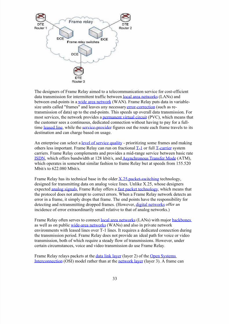
Frame Relay
It is a standardized wide area networking technology that specifies the physical and
logical link layers of digital telecommunications channels using a packet switching methodology. Originally designed for transport across Integrated Services Digital
Network (ISDN) infrastructure, it may be used today in the context of many other
network interfaces. Network providers commonly implement Frame Relay for voice
(VoFR ) and data as an encapsulation technique, used between local area networks (LANs) over a wide area network (WAN). Each end-user gets a private line (or leased
line) to a frame-relay node. The frame-relay network handles the transmission over a
frequently-changing path transparent to all end-users.
With the advent of MPLS, VPN and dedicated broadband services such as cable modem
and DSL, the end may loom for the Frame Relay protocol and encapsulation. [citation needed ]
However many rural areas remain lacking DSL and cable modem services. In such cases
the least expensive type of "always-on" connection remains a 64-kbit/s frame-relay line.Thus a retail chain, for instance, may use Frame Relay for connecting rural stores into
their corporate WAN.
32
8/3/2019 Report on Ccna
http://slidepdf.com/reader/full/report-on-ccna 33/59
The designers of Frame Relay aimed to a telecommunication service for cost-efficient
data transmission for intermittent traffic between local area networks (LANs) and between end-points in a wide area network (WAN). Frame Relay puts data in variable-
size units called "frames" and leaves any necessary error-correction (such as re-
transmission of data) up to the end-points. This speeds up overall data transmission. For most services, the network provides a permanent virtual circuit (PVC), which means that
the customer sees a continuous, dedicated connection without having to pay for a full-
time leased line, while the service-provider figures out the route each frame travels to itsdestination and can charge based on usage.
An enterprise can select a level of service quality - prioritizing some frames and making
others less important. Frame Relay can run on fractional T-1 or full T-carrier system
carriers. Frame Relay complements and provides a mid-range service between basic rateISDN, which offers bandwidth at 128 kbit/s, and Asynchronous Transfer Mode (ATM),
which operates in somewhat similar fashion to frame Relay but at speeds from 155.520
Mbit/s to 622.080 Mbit/s.
Frame Relay has its technical base in the older X.25 packet-switching technology,designed for transmitting data on analog voice lines. Unlike X.25, whose designers
expected analog signals, Frame Relay offers a fast packet technology, which means that
the protocol does not attempt to correct errors. When a Frame Relay network detects anerror in a frame, it simply drops that frame. The end points have the responsibility for
detecting and retransmitting dropped frames. (However, digital networks offer an
incidence of error extraordinarily small relative to that of analog networks.)
Frame Relay often serves to connect local area networks (LANs) with major backbones
as well as on public wide-area networks (WANs) and also in private network environments with leased lines over T-1 lines. It requires a dedicated connection during
the transmission period. Frame Relay does not provide an ideal path for voice or video
transmission, both of which require a steady flow of transmissions. However, under certain circumstances, voice and video transmission do use Frame Relay.
Frame Relay relays packets at the data link layer (layer 2) of the Open Systems
Interconnection (OSI) model rather than at the network layer (layer 3). A frame can
33
8/3/2019 Report on Ccna
http://slidepdf.com/reader/full/report-on-ccna 34/59
incorporate packets from different protocols such as Ethernet and X.25. It varies in size
up to a thousand bytes or more.
Frame Relay originated as an extension of Integrated Services Digital Network (ISDN).
Its designers aimed to enable a packet-switched network to transport the circuit-switched
technology. The technology has become a stand-alone and cost-effective means of
creating a WAN.
Frame Relay switches create virtual circuits to connect remote LANs to a WAN. TheFrame Relay network exists between a LAN border device, usually a router, and the
carrier switch. The technology used by the carrier to transport the data between the
switches is variable and changes between carrier (i.e. Frame Relay does not rely directlyon the transportation mechanism to function).
The sophistication of the technology requires a thorough understanding of the terms used
to describe how Frame Relay works. Without a firm understanding of Frame Relay, it isdifficult to troubleshoot its performance.
Frame Relay has become one of the most extensively-used WAN protocols. Its cheapness
(compared to leased lines) provided one reason for its popularity. The extreme simplicityof configuring user equipment in a Frame Relay network offers another reason for FrameRelay's popularity.
Frame-relay frame structure essentially mirrors almost exactly that defined for LAP-D.
Traffic analysis can distinguish Frame Relay format from LAP-D by its lack of a control
field.
Each Frame Relay Protocol data unit (PDU) consists of the following fields:
1. Flag Field. The flag is used to perform high-level data link synchronization
which indicates the beginning and end of the frame with the unique pattern01111110. To ensure that the 01111110 pattern does not appear somewhere inside
the frame, bit stuffing and destuffing procedures are used.2. Address Field. Each address field may occupy either octet 2 to 3, octet 2 to 4, or
octet 2 to 5, depending on the range of the address in use. A two-octet address
field comprises the EA=ADDRESS FIELD EXTENSION BITS and theC/R=COMMAND/RESPONSE BIT.
1. DLCI-Data Link Connection Identifier Bits. The DLCI serves to identify
the virtual connection so that the receiving end knows which informationconnection a frame belongs to. Note that this DLCI has only local
significance. A single physical channel can multiplex several different
virtual connections.2. FECN, BECN, DE bits. These bits report congestion:
FECN=Forward Explicit Congestion Notification bit
BECN=Backward Explicit Congestion Notification bit
DE=Discard Eligibility bit3. Information Field. A system parameter defines the maximum number of data
bytes that a host can pack into a frame. Hosts may negotiate the actual maximum
frame length at call set-up time. The standard specifies the maximum information
34
8/3/2019 Report on Ccna
http://slidepdf.com/reader/full/report-on-ccna 35/59
field size (supportable by any network) as at least 262 octets. Since end-to-end
protocols typically operate on the basis of larger information units, Frame Relayrecommends that the network support the maximum value of at least 1600 octets
in order to avoid the need for segmentation and reassembling by end-users.
4. Frame Check Sequence (FCS) Field. Since one cannot completely ignore the biterror-rate of the medium, each switching node needs to implement error detection
to avoid wasting bandwidth due to the transmission of err ed frames. The error
detection mechanism used in Frame Relay uses the cyclic redundancy check
(CRC) as its basis.
The Frame Relay network uses a simplified protocol at each switching node. It achieves
simplicity by omitting link-by-link flow-control. As a result, the offered load has largely
determined the performance of Frame Relay networks. When offered load is high, due tothe bursts in some services, temporary overload at some Frame Relay nodes causes a
collapse in network throughput. Therefore, frame-relay networks require some effective
mechanisms to control the congestion.
Congestion control in frame-relay networks includes the following elements:
1. Admission Control. This provides the principal mechanism used in Frame Relayto ensure the guarantee of resource requirement once accepted. It also serves
generally to achieve high network performance. The network decides whether to
accept a new connection request, based on the relation of the requested trafficdescriptor and the network's residual capacity. The traffic descriptor consists of a
set of parameters communicated to the switching nodes at call set-up time or at
service-subscription time, and which characterizes the connection's statistical properties. The traffic descriptor consists of three elements:
2. Committed Information Rate (CIR). The average rate (in bit/s) at which the
network guarantees to transfer information units over a measurement interval T.
This T interval is defined as: T = Bc/CIR.
3. Committed Burst Size (BC). The maximum number of information unitstransmittable during the interval T.
4. Excess Burst Size (BE). The maximum number of uncommitted information units(in bits) that the network will attempt to carry during the interval.
Once the network has established a connection, the edge node of the Frame Relay
network must monitor the connection's traffic flow to ensure that the actual usage of
network resources does not exceed this specification. Frame Relay defines somerestrictions on the user's information rate. It allows the network to enforce the end user's
information rate and discard information when the subscribed access rate is exceeded.
Explicit congestion notification is proposed as the congestion avoidance policy. It tries tokeep the network operating at its desired equilibrium point so that a certain Quality of Service (QoS) for the network can be met. To do so, special congestion control bits have
been incorporated into the address field of the Frame Relay: FECN and BECN. The basic
idea is to avoid data accumulation inside the network. FECN means Forward ExplicitCongestion Notification. The FECN bit can be set to 1 to indicate that congestion was
experienced in the direction of the frame transmission, so it informs the destination that
congestion has occurred. BECN means Backwards Explicit Congestion Notification. The
35
8/3/2019 Report on Ccna
http://slidepdf.com/reader/full/report-on-ccna 36/59
BECN bit can be set to 1 to indicate that congestion was experienced in the network in
the direction opposite of the frame transmission, so it informs the sender that congestionhas occurred.
DLCI number- data link connection identifier It is a set of numbers that is used to identify a set of particular
connection on WAN. It is used to identify the lines of connection
There is a change in putting the IP at the serial port while using
frame relay
See the commands
Router(config)#int s2/0 Router(config-if)#no shut
Router(config-if)#encapsulation frame-relay
Router(config)#int s2/0.1 point
upRouter(config-subif)#ip address 30.0.0.2 255.0.0.0
Router(config-subif)#frame-relay int
Router(config-subif)#frame-relay interface-dlci 102
Router(config-subif)#^Z
Virtual circuit
n telecommunications and computer networks, a virtual circuit (VC), synonymous with
virtual connection and virtual channel, is a connection oriented communication servicethat is delivered by means of packet mode communication. After a connection or virtual
circuit is established between two nodes or application processes, a bit stream or byte
stream may be delivered between the nodes; a virtual circuit protocol allows higher level protocols to avoid dealing with the division of data into segments, packets, or frames.
Virtual circuit communication resembles circuit switching, since both are connection
oriented, meaning that in both cases data is delivered in correct order, and signalling
overhead is required during a connection establishment phase. However, circuit switching provides constant bit rate and latency, while these may vary in a virtual circuit service
because of reasons such as:
• varying packet queue lengths in the network nodes,
• varying bit rate generated by the application,
• varying load from other users sharing the same network resources by means of
statistical multiplexing, etc.
36
8/3/2019 Report on Ccna
http://slidepdf.com/reader/full/report-on-ccna 37/59
Many virtual circuit protocols, but not all, provide reliable communication service, by
means of data retransmissions because of error detection and automatic repeat request (ARQ).
Permanent and switched virtual circuits in ATM, frame
relay
Switched virtual circuits (SVCs) are generally set up on a per-call basis and aredisconnected when the call is terminated; however, a permanent virtual circuit (PVC)
can be established as an option to provide a dedicated circuit link between two facilities.
PVC configuration is usually preconfigured by the service provider. Unlike SVCs, PVCare usually very seldom broken/disconnected.
A switched virtual circuit (SVC) is a virtual circuit that is dynamically established on
demand and is torn down when transmission is complete, for example after a phone callor a file download. SVCs are used in situations where data transmission is sporadic
and/or not always between the same data terminal equipment (DTE) endpoints.
A permanent virtual circuit (PVC) is a virtual circuit established for repeated/continuoususe between the same DTE. In a PVC, the long-term association is identical to the datatransfer phase of a virtual call. Permanent virtual circuits eliminate the need for repeated
call set-up and clearing.
Frame relay is typically used to provide PVCs. ATM provides both switched virtual
connections and permanent virtual connections, as they are called in ATMterminology
Device used in frame relay
CSU/DSU
A CSU/DSU (Channel Service Unit/Data Service Unit) is a digital-interface device used
to connect a Data Terminal Equipment device or DTE, such as a router , to a digital circuit
(for example a T1 or T3 line).
A CSU/DSU operates at the physical layer (layer 1) of the OSI model. CSU/DSUs arealso made as separate physical products; CSUs and DSUs. The DSU or both functions
may be included as part of an interface card inserted into a DTE. If the CSU/DSU is
external, the DTE interface is usually compatible with the V.xx or RS-232C or similar
serial interface.
Digital lines require both a channel service unit (CSU) and a data service unit (DSU):
• connection to a DTE device and provides timing to each end.
WIC (Wan Interface Card)
37
8/3/2019 Report on Ccna
http://slidepdf.com/reader/full/report-on-ccna 38/59
The WIC (WAN Interface Card) may contain an integrated CSU/DSU that can be
inserted into a router slot. An example of a WIC is the 1-port 56/64-kbit/s DSU/CSUWIC (WIC-1DSU-56K4) from Cisco.
Well our network is ready to communicate between each other…we have some
application which we can implement on our networks.
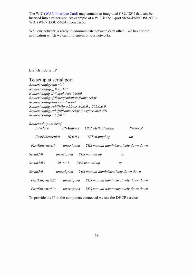
Branch 1 Serial IP
To set ip at serial port Router(config)#int s2/0
Router(config-if)#no shut
Router(config-if)#clock rate 64000 Router(config-if)#encapsulation frame-relay
Router(config)#int s2/0.1 point
Router(config-subif)#ip address 30.0.0.1 255.0.0.0
Router(config-subif)#frame-relay interface-dlci 201 Router(config-subif)#^Z
Router#sh ip int brief Interface IP-Address OK? Method Status Protocol
FastEthernet0/0 10.0.0.1 YES manual up up
FastEthernet1/0 unassigned YES manual administratively down down
Serial2/0 unassigned YES manual up up
Serial2/0.1 30.0.0.1 YES manual up up
Serial3/0 unassigned YES manual administratively down down
FastEthernet4/0 unassigned YES manual administratively down down
FastEthernet5/0 unassigned YES manual administratively down down
To provide the IP to the computers connected we use the DHCP service
38
8/3/2019 Report on Ccna
http://slidepdf.com/reader/full/report-on-ccna 39/59
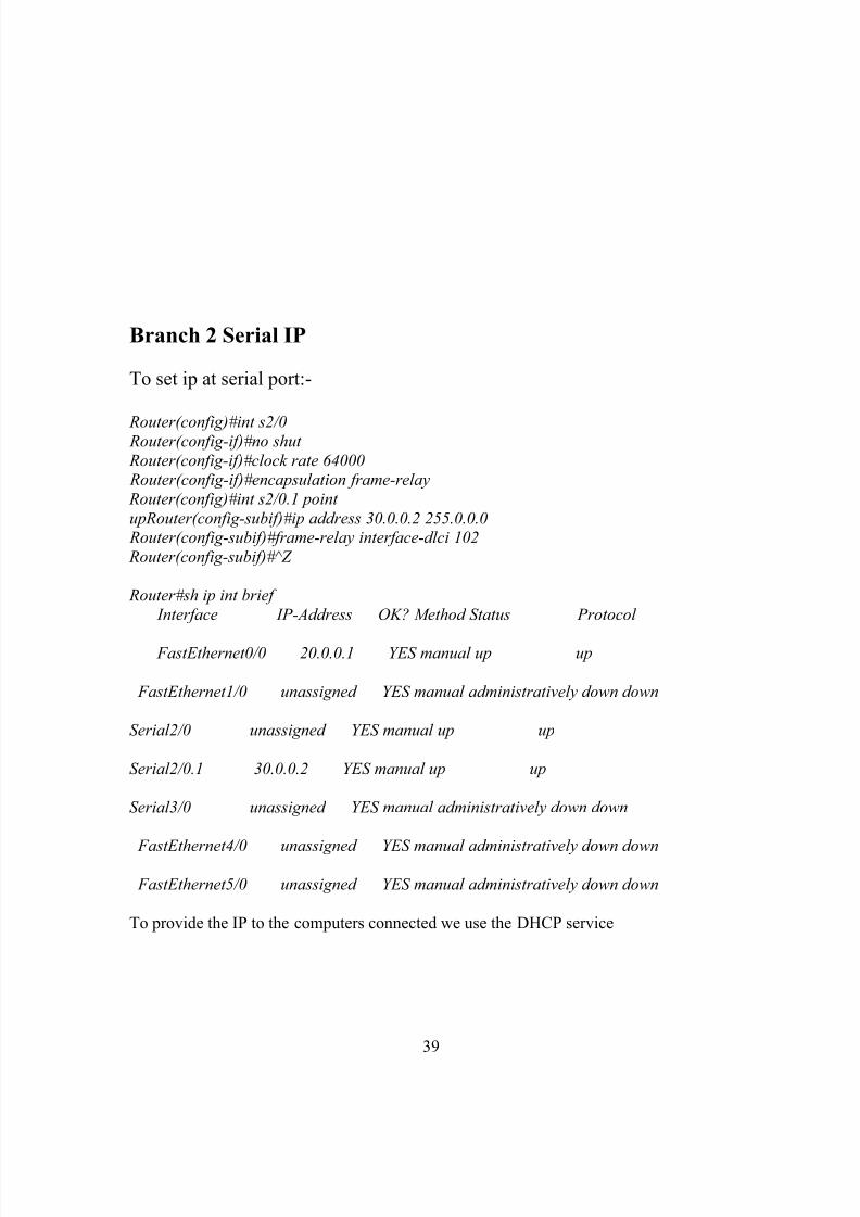
Branch 2 Serial IP
To set ip at serial port:-
Router(config)#int s2/0 Router(config-if)#no shut
Router(config-if)#clock rate 64000 Router(config-if)#encapsulation frame-relay
Router(config)#int s2/0.1 point
upRouter(config-subif)#ip address 30.0.0.2 255.0.0.0 Router(config-subif)#frame-relay interface-dlci 102
Router(config-subif)#^Z
Router#sh ip int brief
Interface IP-Address OK? Method Status Protocol
FastEthernet0/0 20.0.0.1 YES manual up up
FastEthernet1/0 unassigned YES manual administratively down down
Serial2/0 unassigned YES manual up up
Serial2/0.1 30.0.0.2 YES manual up up
Serial3/0 unassigned YES manual administratively down down
FastEthernet4/0 unassigned YES manual administratively down down
FastEthernet5/0 unassigned YES manual administratively down down
To provide the IP to the computers connected we use the DHCP service
39
8/3/2019 Report on Ccna
http://slidepdf.com/reader/full/report-on-ccna 40/59
Routing
What is Routing ?
o The term “routing” is used for taking a packet from one device and sending it
through the network to another device on a different network.o Routers don’t really care about hosts—they only care about networks and the best
path to each network.
Routers route traffic to all the networks in your internetwork. To be able to route packets,
a router must know, at a minimum, the following:
Destination address
Neighbor routers from which it can learn about remote networks
Possible routes to all remote networks
The best route to each remote network How to maintain and verify routing information
Routing Example :
40
8/3/2019 Report on Ccna
http://slidepdf.com/reader/full/report-on-ccna 41/59
192.168.10.2
Internet
192.168.20.2
192.168.10.1
F0/0
192.168.20.1
F0/0
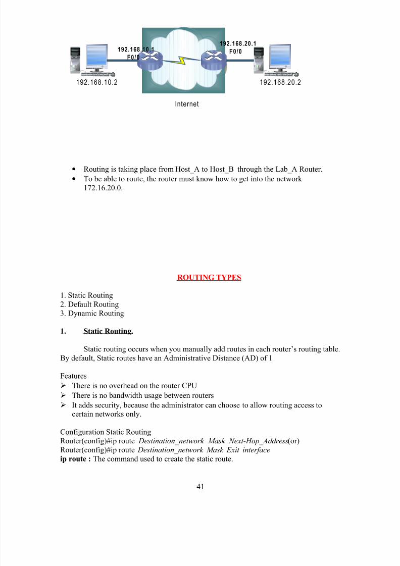
• Routing is taking place from Host_A to Host_B through the Lab_A Router.
• To be able to route, the router must know how to get into the network
172.16.20.0.
ROUTING TYPES
1. Static Routing2. Default Routing
3. Dynamic Routing
1. Static Routing.
Static routing occurs when you manually add routes in each router’s routing table.
By default, Static routes have an Administrative Distance (AD) of 1
Features
There is no overhead on the router CPU
There is no bandwidth usage between routers It adds security, because the administrator can choose to allow routing access to
certain networks only.
Configuration Static RoutingRouter(config)#ip route Destination_network Mask Next-Hop_Address(or)
Router(config)#ip route Destination_network Mask Exit interface
ip route : The command used to create the static route.
41
8/3/2019 Report on Ccna
http://slidepdf.com/reader/full/report-on-ccna 42/59
destination_network : The network you’re placing in the routing table.
mask : The subnet mask being used on the network.
next-hop_address : The address of the next-hop router
Exitinterface : You can use it in place of the next-hop address
administrative_distance : By default, static routes have an administrative distance of 1
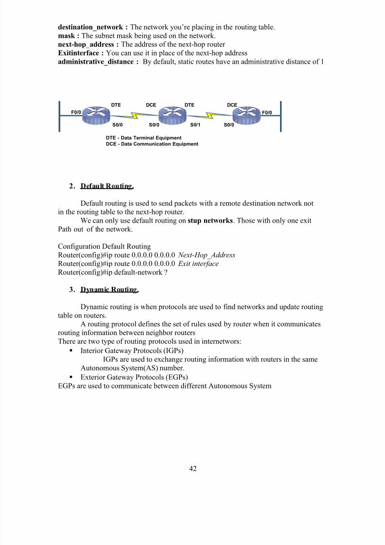
F0/0 F0/0
S0/0 S0/0 S0/1 S0/0
DTE DCE DTE DCE
DTE - Data Terminal Equipment
DCE - Data Communication Equipment
2. Default Routing.
Default routing is used to send packets with a remote destination network notin the routing table to the next-hop router.
We can only use default routing on stup networks. Those with only one exit
Path out of the network.
Configuration Default Routing
Router(config)#ip route 0.0.0.0 0.0.0.0 Next-Hop_Address
Router(config)#ip route 0.0.0.0 0.0.0.0 Exit interface
Router(config)#ip default-network ?
3. Dynamic Routing.
Dynamic routing is when protocols are used to find networks and update routing
table on routers.A routing protocol defines the set of rules used by router when it communicates
routing information between neighbor routers
There are two type of routing protocols used in internetwors:
Interior Gateway Protocols (IGPs)
IGPs are used to exchange routing information with routers in the same
Autonomous System(AS) number.
Exterior Gateway Protocols (EGPs)
EGPs are used to communicate between different Autonomous System
42
8/3/2019 Report on Ccna
http://slidepdf.com/reader/full/report-on-ccna 43/59
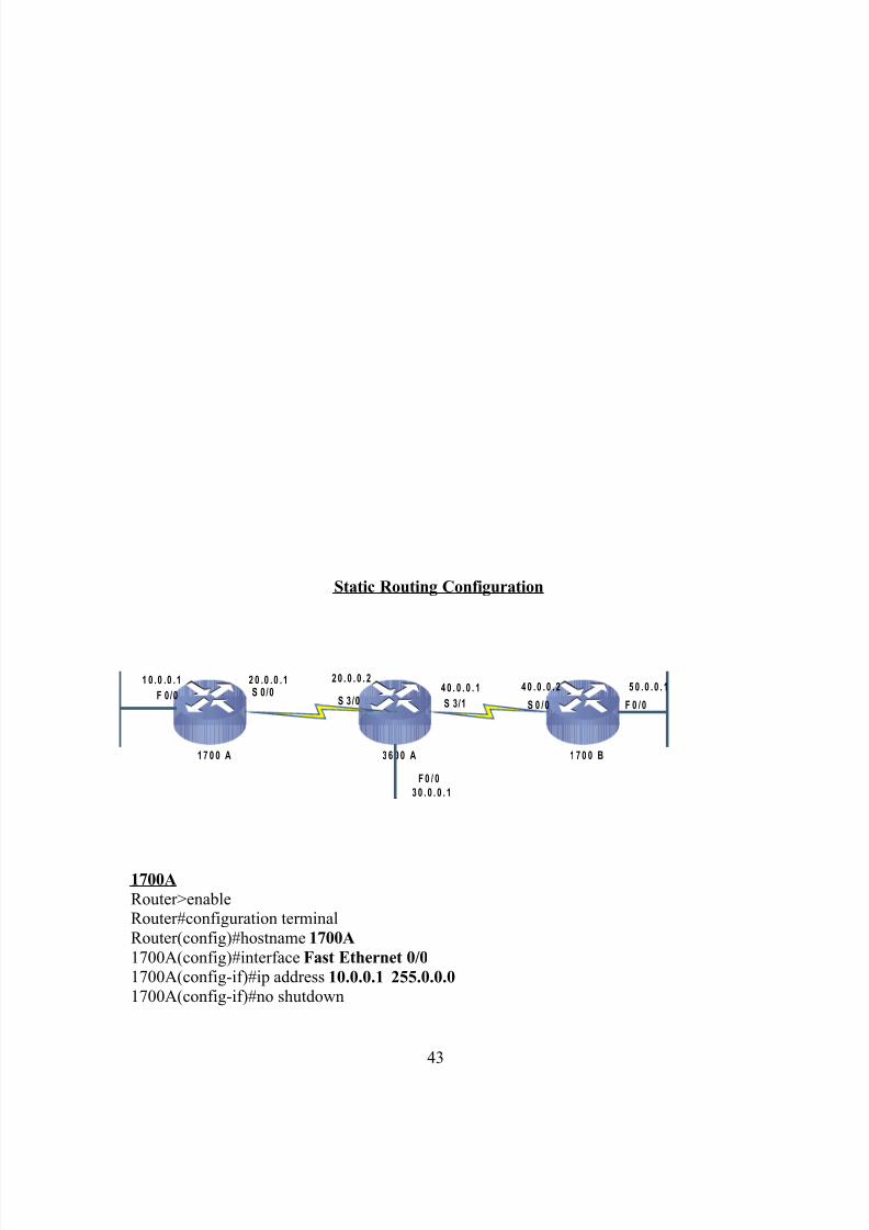
Static Routing Configuration
1 7 0 0 A 3 6 0 0 A 1 7 0 0 B
F 0 /0 S 0 /0S 3 /0 S 3/1 S 0 / 0 F 0 / 0
1 0 .0 .0 . 1 2 0 .0 . 0 . 1 2 0 . 0 . 0 . 24 0 . 0 . 0 . 1 4 0 . 0 . 0 . 2 5 0 . 0 . 0 . 1
F 0 / 0
3 0 . 0 . 0 . 1
1700A
Router>enableRouter#configuration terminal
Router(config)#hostname 1700A
1700A(config)#interface Fast Ethernet 0/0
1700A(config-if)#ip address 10.0.0.1 255.0.0.0
1700A(config-if)#no shutdown
43
8/3/2019 Report on Ccna
http://slidepdf.com/reader/full/report-on-ccna 44/59
1700A(config)#interface Serial 0/0
1700A(config-if)#ip address 20.0.0.1. 255.0.0.0
1700A(config-if)#no shutdown
1700A(config-if)#control Z
1700A#show ip route1700A#show ip interface brief
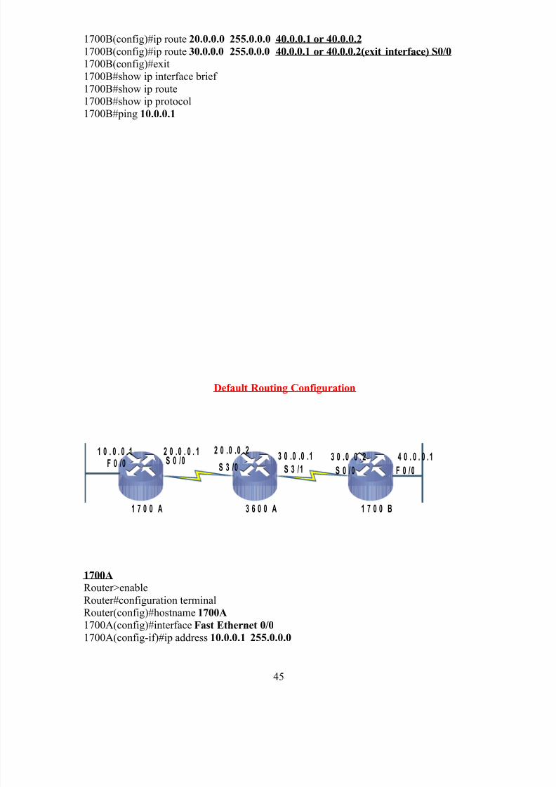
1700A(config)#ip route 30.0.0.0 255.0.0.0 20.0.0.2 or S0/0 exit interface
1700A(config)#ip route 40.0.0.0 255.0.0.0 20.0.0.2 or S0/0 (exit interface)
1700A(config)#ip route 50.0.0.0 255.0.0.0 20.0.0.2 or S0/0 (exit interface)1700A(config)#exit
1700A#show ip interface brief
1700A# show ip protocol
3600A
Router>enableRouter#configuration terminal
Router(config)#hostname 3600A
3600A(config)#interface S3/0
3600A(config-if)#ip address 20.0.0.2 255.0.0.0
3600A(config-if)#no shutdown3600A#show controllers S3/0 (to see a DCE end or DTE end)
3600A(config-if)#clock rate 64000
3600A(config)#interface Serial 3/1
3600A(config-if)#ip address 30.0.0.1. 255.0.0.0
3600A(config-if)#no shutdown3600A(config-if)#clock rate 64000
3600A(config-if)#control Z
3600A#show ip route3600A#show ip interface brief
3600A(config)#ip route 10.0.0.0 255.0.0.0 20.0.0.1 or 20.0.0.2
3600A(config)#ip route 50.0.0.0 255.0.0.0 40.0.0.2 or 40.0.0.13600A(config)#exit3600A#show ip interface brief
3600A# show ip protocol
1700B
Router>enable
Router#configuration terminalRouter(config)#hostname 1700B
1700B(config)#interface Fast Ethernet 0/0
1700B(config-if)#ip address 40.0.0.1 255.0.0.0
1700B(config-if)#no shutdown1700B(config)#interface Serial 0/0
1700B(config-if)#ip address 30.0.0.2 255.0.0.0
1700B(config-if)#no shutdown1700B(config-if)#control Z
1700B#show ip route
1700B#show ip interface brief 1700B(config)#ip route 10.0.0.0 255.0.0.0 40.0.0.1 or 40.0.0.2
44
8/3/2019 Report on Ccna
http://slidepdf.com/reader/full/report-on-ccna 45/59
1700B(config)#ip route 20.0.0.0 255.0.0.0 40.0.0.1 or 40.0.0.2
1700B(config)#ip route 30.0.0.0 255.0.0.0 40.0.0.1 or 40.0.0.2(exit interface) S0/0
1700B(config)#exit
1700B#show ip interface brief
1700B#show ip route1700B#show ip protocol
1700B#ping 10.0.0.1
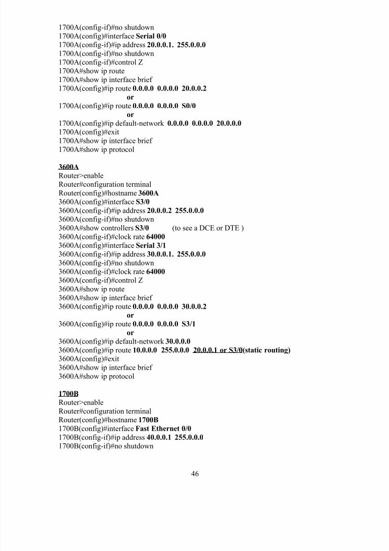
Default Routing Configuration
1 7 0 0 A 3 6 0 0 A 1 7 0 0 B
F 0 /0 S 0 /0S 3 /0 S 3 /1 S 0 / 0 F 0 / 0
1 0 . 0 . 0 . 1 2 0 . 0 . 0 . 1 2 0 .0 .0 .23 0 . 0 . 0 .2 4 0 . 0 . 0 . 13 0 .0 .0 .1
1700A
Router>enable
Router#configuration terminalRouter(config)#hostname 1700A
1700A(config)#interface Fast Ethernet 0/0
1700A(config-if)#ip address 10.0.0.1 255.0.0.0
45
8/3/2019 Report on Ccna
http://slidepdf.com/reader/full/report-on-ccna 46/59
1700A(config-if)#no shutdown
1700A(config)#interface Serial 0/0
1700A(config-if)#ip address 20.0.0.1. 255.0.0.0
1700A(config-if)#no shutdown
1700A(config-if)#control Z1700A#show ip route
1700A#show ip interface brief
1700A(config)#ip route 0.0.0.0 0.0.0.0 20.0.0.2
or1700A(config)#ip route 0.0.0.0 0.0.0.0 S0/0
or
1700A(config)#ip default-network 0.0.0.0 0.0.0.0 20.0.0.0
1700A(config)#exit
1700A#show ip interface brief
1700A#show ip protocol
3600A
Router>enableRouter#configuration terminal
Router(config)#hostname 3600A3600A(config)#interface S3/0
3600A(config-if)#ip address 20.0.0.2 255.0.0.0
3600A(config-if)#no shutdown
3600A#show controllers S3/0 (to see a DCE or DTE )
3600A(config-if)#clock rate 64000
3600A(config)#interface Serial 3/1
3600A(config-if)#ip address 30.0.0.1. 255.0.0.0
3600A(config-if)#no shutdown3600A(config-if)#clock rate 64000
3600A(config-if)#control Z
3600A#show ip route3600A#show ip interface brief 3600A(config)#ip route 0.0.0.0 0.0.0.0 30.0.0.2
or
3600A(config)#ip route 0.0.0.0 0.0.0.0 S3/1
or
3600A(config)#ip default-network 30.0.0.0
3600A(config)#ip route 10.0.0.0 255.0.0.0 20.0.0.1 or S3/0(static routing)
3600A(config)#exit
3600A#show ip interface brief
3600A#show ip protocol
1700B
Router>enable
Router#configuration terminalRouter(config)#hostname 1700B
1700B(config)#interface Fast Ethernet 0/0
1700B(config-if)#ip address 40.0.0.1 255.0.0.0
1700B(config-if)#no shutdown
46
8/3/2019 Report on Ccna
http://slidepdf.com/reader/full/report-on-ccna 47/59
1700B(config)#interface Serial 0/0
1700B(config-if)#ip address 30.0.0.2 255.0.0.0
1700B(config-if)#no shutdown
1700B(config-if)#control Z
1700B#show ip route1700B#show ip interface brief
1700B(config)#ip route 0.0.0.0 0.0.0.0 30.0.0.1
or
1700B(config)#ip route 0.0.0.0 0.0.0.0 S0/0or
1700B(config)#ip default-network 30.0.0.0
1700B(config)#exit1700B#show ip interface brief
1700B#show ip route
1700B#show ip protocol1700B#ping 10.0.0.1
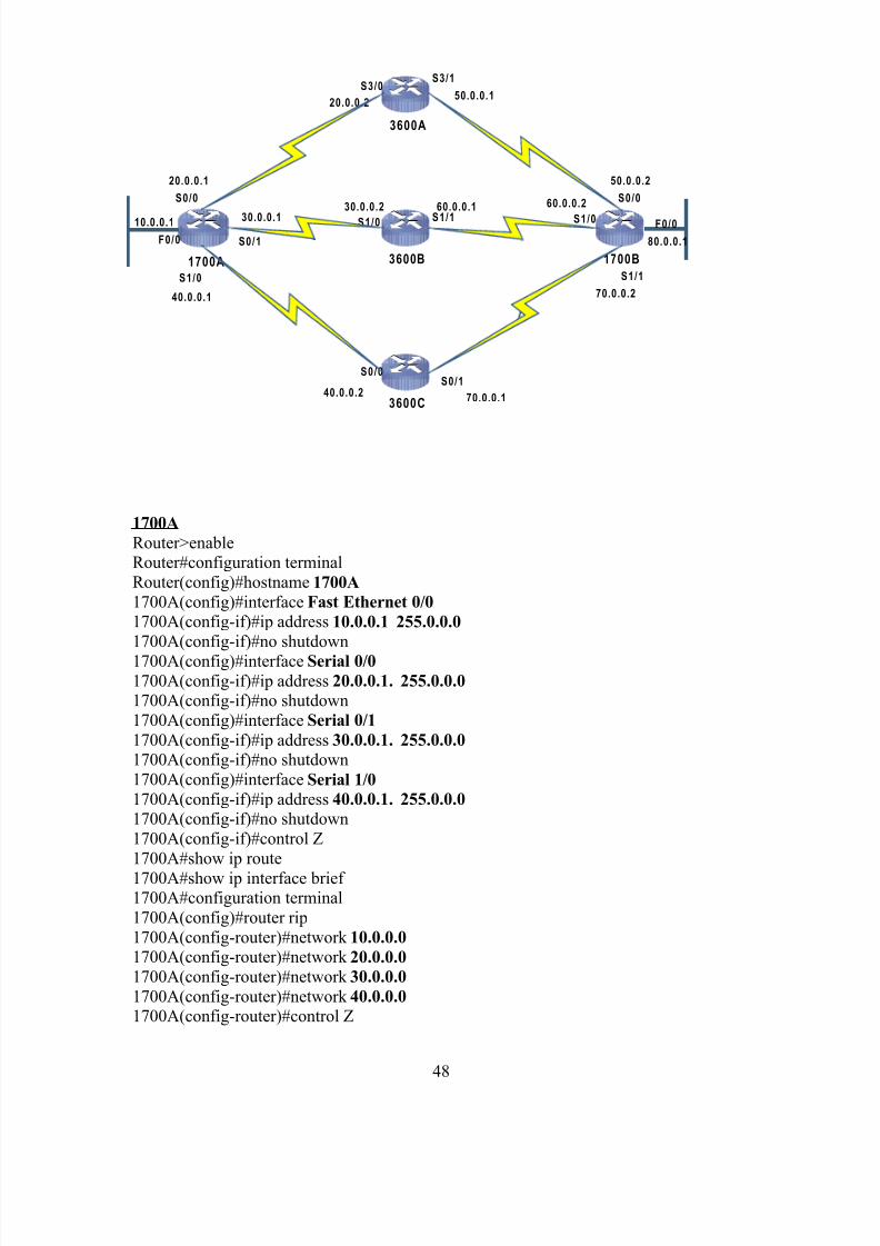
RIP (Routing Information Protocol) Configuration
47
8/3/2019 Report on Ccna
http://slidepdf.com/reader/full/report-on-ccna 48/59
1700A 3600B 1700B
3600A
3600C
S0/0
20.0.0.1
S1/0
40.0.0.1
F0/0
F0/0
S0/0S0/1
40.0.0.270.0.0.1
S0/0
S1/0
60.0.0.2
S1/1
60.0.0.1
S1/0
30.0.0.2
S0/1
30.0.0.1
S3/0
20.0.0.2
S3/1
50.0.0.1
50.0.0.2
S1/1
70.0.0.2
10.0.0.1
80.0.0.1
1700A
Router>enableRouter#configuration terminal
Router(config)#hostname 1700A
1700A(config)#interface Fast Ethernet 0/0
1700A(config-if)#ip address 10.0.0.1 255.0.0.0
1700A(config-if)#no shutdown
1700A(config)#interface Serial 0/0
1700A(config-if)#ip address 20.0.0.1. 255.0.0.0
1700A(config-if)#no shutdown
1700A(config)#interface Serial 0/1
1700A(config-if)#ip address 30.0.0.1. 255.0.0.0
1700A(config-if)#no shutdown
1700A(config)#interface Serial 1/0
1700A(config-if)#ip address 40.0.0.1. 255.0.0.0
1700A(config-if)#no shutdown
1700A(config-if)#control Z
1700A#show ip route
1700A#show ip interface brief 1700A#configuration terminal
1700A(config)#router rip
1700A(config-router)#network 10.0.0.0
1700A(config-router)#network 20.0.0.0
1700A(config-router)#network 30.0.0.0
1700A(config-router)#network 40.0.0.0
1700A(config-router)#control Z
48
8/3/2019 Report on Ccna
http://slidepdf.com/reader/full/report-on-ccna 49/59
1700A#show ip route
1700A#show ip interface brief 1700A#show ip protocol
3600A
Router>enable
Router#configuration terminal
Router(config)#hostname 3600A
3600A(config)#interface S3/03600A(config-if)#ip address 20.0.0.2 255.0.0.0
3600A(config-if)#no shutdown
3600A(config-if)#clock rate 64000
3600A(config)#interface Serial 3/1
3600A(config-if)#ip address 50.0.0.1. 255.0.0.0
3600A(config-if)#no shutdown3600A(config-if)#clock rate 64000
3600A(config-if)#exit
3600A(config)#router rip3600A(config-router)#network 20.0.0.0
3600A(config-router)#network 50.0.0.03600A(config-router)#control Z
3600A#show ip route3600A#show ip interface brief
3600A# show ip protocol
3600B
Router>enable
Router#configuration terminalRouter(config)#hostname 3600B
3600B(config)#interface S1/0
3600B(config-if)#ip address 30.0.0.2 255.0.0.03600B(config-if)#no shutdown3600B(config-if)#clock rate 64000
3600B(config)#interface Serial 1/1
3600B(config-if)#ip address 60.0.0.1. 255.0.0.0
3600B(config-if)#no shutdown
3600B(config-if)#clock rate 64000
3600B(config-if)#exit3600B(config)#router rip
3600B(config-router)#network 30.0.0.0
3600B(config-router)#network 60.0.0.0
3600A(config-router)#control Z3600B#show ip route
3600B#show ip interface brief
3600B# show ip protocol
3600C
Router>enableRouter#configuration terminal
49
8/3/2019 Report on Ccna
http://slidepdf.com/reader/full/report-on-ccna 50/59
Router(config)#hostname 3600C
3600C(config)#interface S0/0
3600C(config-if)#ip address 40.0.0.2 255.0.0.0
3600C(config-if)#no shutdown
3600C(config-if)#clock rate 64000
3600C(config)#interface Serial 0/1
3600C(config-if)#ip address 70.0.0.1. 255.0.0.0
3600C(config-if)#no shutdown
3600C(config-if)#clock rate 640003600C(config-if)#exit
3600C(config)#router rip
3600C(config-router)#network 40.0.0.0
3600C(config-router)#network 70.0.0.0
3600C(config-router)#control Z
3600C#show ip route3600C#show ip interface brief
1700B
Router>enableRouter#configuration terminal
Router(config)#hostname 1700B
1700B(config)#interface Fast Ethernet 0/0
1700B(config-if)#ip address 80.0.0.1 255.0.0.0
1700B(config-if)#no shutdown1700B(config)#interface Serial 0/0
1700B(config-if)#ip address 50.0.0.2 255.0.0.0
1700B(config-if)#no shutdown1700B(config)#interface Serial 1/0
1700B(config-if)#ip address 60.0.0.2 255.0.0.0
1700B(config-if)#no shutdown1700B(config)#interface Serial 1/1
1700B(config-if)#ip address 70.0.0.2 255.0.0.0
1700B(config-if)#no shutdown
1700B(config-if)#control Z1700B#show ip route
1700B#show ip interface brief
1700B#show ip protocol1700B#configuration terminal
1700B(config)#router rip
1700B(config-router)#network 50.0.0.0
1700B(config-router)#network 60.0.0.01700B(config-router)#network 70.0.0.0
1700B(config-router)#network 80.0.0.0
1700B(config-router)#control Z1700B#show ip interface brief
1700B#show ip protocol
50
8/3/2019 Report on Ccna
http://slidepdf.com/reader/full/report-on-ccna 51/59
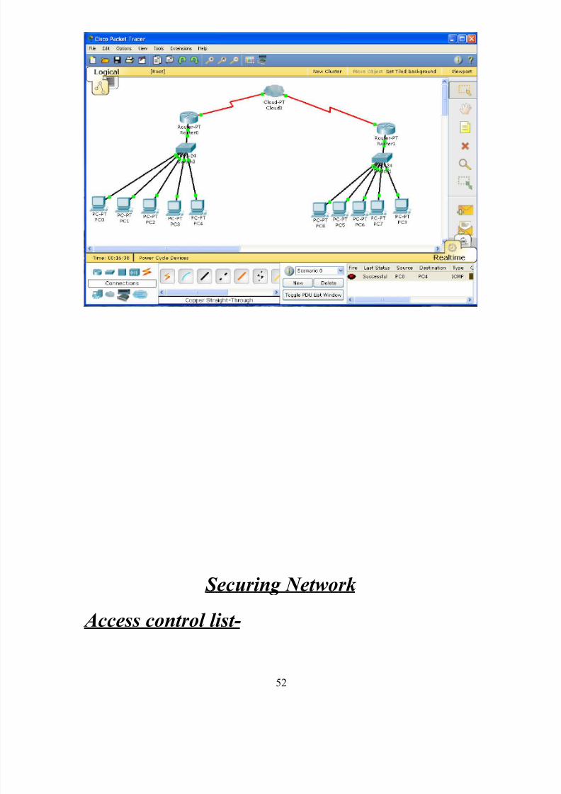
Now first see what is the real network on which
we are working
51
8/3/2019 Report on Ccna
http://slidepdf.com/reader/full/report-on-ccna 52/59
Securing Network
Access control list-
52
8/3/2019 Report on Ccna
http://slidepdf.com/reader/full/report-on-ccna 53/59
It is the set of the commands by which we can filter a network, group together or leave
any interference. An access control list (ACL), with respect to a computer file system,
is a list of permissions attached to an object. An ACL specifies which users or system
processes are granted access to objects, as well as what operations are allowed on given
objects. Each entry in a typical ACL specifies a subject and an operation. For instance, if a file has an ACL that contains (Alice, delete), this would give Alice permission to
delete the file.
Types of access list
a) Standard access list: It is generally used when we want 1 pc of
branch 1 stops communication with all other pc of branch 2 networks.
Numbered Standard Access Control Lists
Numbers between 1 and 99, or any number between 1300 and 1999 can be used in aStandard ACL. The number used in this range doesn't affect how the ACL is processed or
which ACL is more important to the router. A standard ACL is concerned with only onefactor, the source IP address of the packet. The destination is not considered. The number takes the place of a name you might give to a specific rule. The number in no way
corresponds to a list of pre-defined ACL's
Access List Rules
Regardless of the type of access list you create, standard or extended, you must followcertain rules. For instance, you must create and apply access lists sequentially. Also, as
stated earlier, access lists end with an implicit deny.
Router A(config)#access-list 1 deny 172.16.5.2 0.0.0.0
Router A(config)#access-list 1 deny 172.16.5.3 0.0.0.0
Router A(config)#access-list 1 permit any
The previous example is a standard IP access list that denies the hosts 172.16.5.2 and
172.16.5.3, while allowing all other traffic. The list is applied sequentially from the top
down as the router checks the packets arriving at the interface where this access list isapplied, in order to check if the packets match the permit and deny statements.
In the process of applying access lists, the router first checks an arriving packet to
determine if it matches the deny 172.16.5.2 0.0.0.0 statement. If it does, the router
discards the packet. If it does not, the router applies the second statement, deny172.16.5.3 0.0.0.0. If the packet matches the second statement, the router discards the
packet. Once again, if the packet does not meet the rules of the first two lines, the router
applies the final permit any statement, and the packet is forwarded through the interface.
If you wish to remove an access-list, you use the no access-list (list #) command. For example, to remove the above list, you enter global configuration mode and type the no
53
8/3/2019 Report on Ccna
http://slidepdf.com/reader/full/report-on-ccna 54/59
access-list command. The information below shows the correct procedure for typing this
command.
Configuration of Named and Standard Access Control
Lists
Creating Numbered Standard Access Control Lists
From Global Configuration mode, type in:
access-list [access-list-number] [deny/permit] [source-ip-address] [
wildcard mask]
interface [interface-number]
ip access-group [number of list] in/out
As done in our network
b) Extended access list:Extended Access Control is a mechanism
specified to allow only authorized Inspection system (system used to
read e-passport) to read sensitive biometric data such as fingerprints
from ePassports. EAC is mentioned in ICAO Doc 9303 but the description
there is not very clear.
There are several different implementation of the mechanism, that must be implemented
along with the Basic Access Control which is mandatory in the EU. The European
Commission in its decision No 2909 from the 28 June 2006 described what technology
will be used to protect fingerprints in the Member States e-passports. The deadline for themember states to start fingerprint enabled e-passport issuing was set to be 28 June 2009.
The specification selected for the EU e-passports was prepared by the German Federal
Office for Information Security (BSI) in their technical report TR 3110[1]
. Several other countries implement their own EAC.
r1(config)#access-list 101 deny ip host 10.0.0.2 20.0.0.2 0.0.0.0
r1(config)#access-list 101 permit ip any any
r1(config)#int f0/0
r1(config-if)#ip access-group 101 in
r1(config-if)#^Z
here we have done that the pc (0) of branch 1 will not communicate with the pc (0) of
branch 2 but they both will communicate with all other pc’s of the network
54
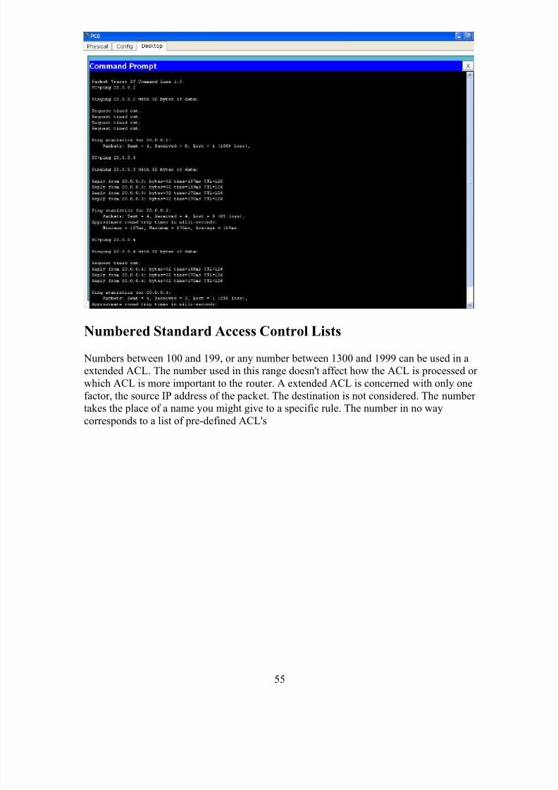
8/3/2019 Report on Ccna
http://slidepdf.com/reader/full/report-on-ccna 55/59
Numbered Standard Access Control Lists
Numbers between 100 and 199, or any number between 1300 and 1999 can be used in aextended ACL. The number used in this range doesn't affect how the ACL is processed or
which ACL is more important to the router. A extended ACL is concerned with only one
factor, the source IP address of the packet. The destination is not considered. The number takes the place of a name you might give to a specific rule. The number in no way
corresponds to a list of pre-defined ACL's
55
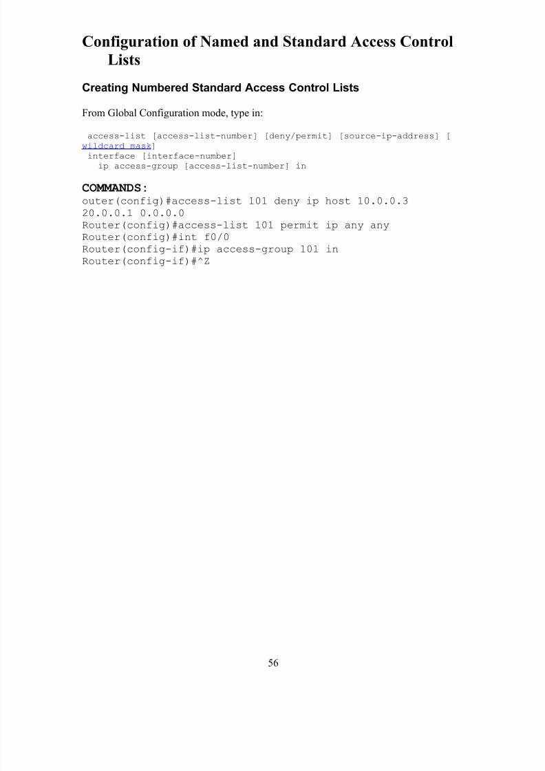
8/3/2019 Report on Ccna
http://slidepdf.com/reader/full/report-on-ccna 56/59
Configuration of Named and Standard Access Control
Lists
Creating Numbered Standard Access Control Lists
From Global Configuration mode, type in:
access-list [access-list-number] [deny/permit] [source-ip-address] [wildcard mask]
interface [interface-number]
ip access-group [access-list-number] in
COMMANDS:
outer(config)#access-list 101 deny ip host 10.0.0.3
20.0.0.1 0.0.0.0
Router(config)#access-list 101 permit ip any any
Router(config)#int f0/0
Router(config-if)#ip access-group 101 in
Router(config-if)#^Z
56
8/3/2019 Report on Ccna
http://slidepdf.com/reader/full/report-on-ccna 57/59
Remotely Working On Cisco Router
Telnet:
TELNET (TELe-NETwork) is a network protocol used on the Internet or local area
networks to provide a bidirectional interactive text-oriented communications facility via a
virtual terminal connection. User data is interspersed in-band with TELNET controlinformation in an 8-bit byte oriented data connection over the Transmission Control
Protocol (TCP).
Telnet was developed in 1969 beginning with RFC 15, extended in RFC 854, and
standardized as Internet Engineering Task Force (IETF) Internet Standard STD 8, one of the first Internet standards.
Historically, telnet provided access to a command-line interface (usually, of an operating
system) on a remote host. Most network equipment and operating systems with a TCP/IPstack support a Telnet service for remote configuration (including systems based on
Windows NT). Because of security issues with Telnet, its use for this purpose has wanedin favor of SSH.
The term telnet may also refer to the software that implements the client part of the protocol. Telnet client applications are available for virtually all computer platforms.
Telnet is also used as a verb. To telnet means to establish a connection with the Telnet
protocol, either with command line client or with a programmatic interface. For example,a common directive might be: "To change your password, telnet to the server, login and
run the passwd command ." Most often, a user will be telnetting to a Unix-like server
system or a network device such as a router and obtain a login prompt to a command line
text interface or a character-based full-screen manager.
Security
When Telnet was initially developed in 1969, most users of networked computers were in
the computer departments of academic institutions, or at large private and government
research facilities. In this environment, security was not nearly as much of a concern as it became after the bandwidth explosion of the 1990s. The rise in the number of people with
access to the Internet, and by extension, the number of people attempting to crack other
people's servers made encrypted alternatives much more of a necessity.
Experts in computer security, such as SANS Institute, recommend that the use of Telnet
for remote logins should be discontinued under all normal circumstances, for thefollowing reasons:
• Telnet, by default, does not encrypt any data sent over the connection (including
passwords), and so it is often practical to eavesdrop on the communications anduse the password later for malicious purposes; anybody who has access to a
router , switch, hub or gateway located on the network between the two hosts
where Telnet is being used can intercept the packets passing by and obtain login
57
8/3/2019 Report on Ccna
http://slidepdf.com/reader/full/report-on-ccna 58/59
and password information (and whatever else is typed) with any of several
common utilities like tcpdump and Wireshark .
• Most implementations of Telnet have no authentication that would ensure
communication is carried out between the two desired hosts and not intercepted in
the middle.
• Commonly used Telnet daemons have several vulnerabilities discovered over the
years.
These security-related shortcomings have seen the usage of the Telnet protocol droprapidly, especially on the public Internet, in favor of the Secure Shell (SSH) protocol,first released in 1995. SSH provides much of the functionality of telnet, with the addition
of strong encryption to prevent sensitive data such as passwords from being intercepted,
and public key authentication, to ensure that the remote computer is actually who itclaims to be. As has happened with other early Internet protocols, extensions to the
Telnet protocol provide Transport Layer Security (TLS) security and Simple
Authentication and Security Layer (SASL) authentication that address the above issues.
However, most Telnet implementations do not support these extensions; and there has been relatively little interest in implementing these as SSH is adequate for most purposes.
The main advantage of TLS-Telnet would be the ability to use certificate-authority signed
server certificates to authenticate a server host to a client that does not yet have the server key stored. In SSH, there is a weakness in that the user must trust the first session to a
host when it has not yet acquired the server key.
Current status
As of the mid-2000s, the Telnet protocol itself has been mostly superseded for remotelogin. Telnet is popular in various application areas:
• Enterprise networks to access host applications, e.g., on IBM Mainframes.
• Administration of network elements, e.g., in commissioning, integration and
maintenance of core network elements in mobile communication networks, andmany industrial control systems.
• MUD games played over the Internet, as well as talkers, MUSHes, MUCKs,
MOOes, and the resurgent BBS community.
• Internet game clubs, like the Internet Chess Club, the Free Internet Chess Server
and the Internet Go server .
• Embedded systems.
• Mobile data collection applications where telnet runs over secure networks
• Collaboration of multiple users where the capability of session transfer, swap,
sharing, and recovery of disconnected sessions is needed.[4]
Also note that Telnet is a component of FTP protocol. FTP control data are transmitted inTelnet format, although some software implements it incorrectly.
58
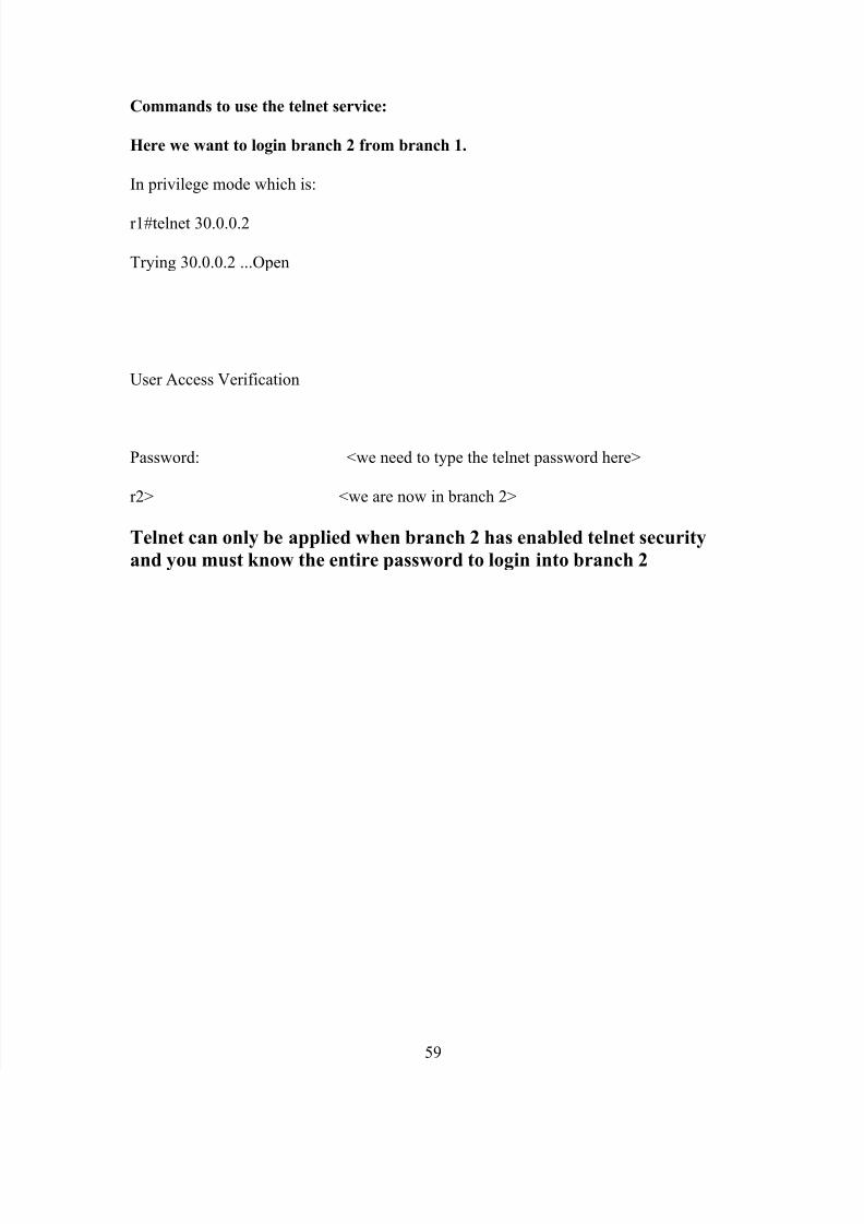
8/3/2019 Report on Ccna
http://slidepdf.com/reader/full/report-on-ccna 59/59
Commands to use the telnet service:
Here we want to login branch 2 from branch 1.
In privilege mode which is:
r1#telnet 30.0.0.2
Trying 30.0.0.2 ...Open
User Access Verification
Password: <we need to type the telnet password here>
r2> <we are now in branch 2>
Telnet can only be applied when branch 2 has enabled telnet security
and you must know the entire password to login into branch 2


![Ccna Project Report[1]](https://img.pdfslide.net/doc/110x75/54fb15d94a795956048b5011/ccna-project-report1.jpg)