Embed Size (px)
Citation preview
This report consists of 47 pages. Abridged or partial reproduction or copying of this report requires the permission of the Department of Solid Structures and Building Design at the TU Kaiserslautern.
Project: 21046HK15511
Report on fire evaluation of post-installed rebar connections with fischer injection system FIS V Zero
Client: fischerwerke GmbH & Co. KG
Otto-Hahn-Straße 15
D – 79211 Denzlingen
Author: Heiner Kruse M.Sc.
Date: 12.05.2021
Valit until: 12.05.2026
________________________ ________________________
apl. Prof. Dr.-Ing. Catherina Thiele Heiner Kruse M.Sc.
BAUINGENIEURWESEN
Fachgebiet Massivbau und Baukonstruktion
apl. Prof. Dr.-Ing. Catherina Thiele AG Experimenteller Massivbau Paul-Ehrlich-Straße Gebäude 14 67663 Kaiserslautern Telefon: +49 (0)631 205-3833 Telefax: +49 (0)631 205-3555 [email protected] www.massivbau-kl.de
21046HK15511
Report on fire evaluation of post-installed rebar connections with fischer injection system FIS V Zero
2
Table of contents
1. General ..................................................................................................................................... 3
2. The evaluated elements .......................................................................................................... 3
3. Design method ......................................................................................................................... 3
4. Simulation input ...................................................................................................................... 5
5. Structural connections ............................................................................................................ 7
6. Simulation results.................................................................................................................... 9 6.1. Maximum applicable bond stress for slab-slab connections ................................................................... 9 6.2. Maximum applicable loads for beam-wall connections ......................................................................... 11 6.2.1. Maximum applicable loads for a beam-wall connection with a concrete cover of 10mm ................. 12 6.2.2. Maximum applicable loads for a beam-wall connection with a concrete cover of 20mm ................. 14 6.2.3. Maximum applicable loads for a beam-wall connection with a concrete cover of 30mm ................. 20 6.2.4. Maximum applicable loads for a beam-wall connection with a concrete cover of 40mm ................. 29 6.2.5. Maximum applicable loads for a beam-wall connection with a concrete cover of 55mm ................. 38
7. References ............................................................................................................................. 47

21046HK15511
Report on fire evaluation of post-installed rebar connections with fischer injection system FIS V Zero
3
1. General
The Technical University of Kaiserslautern had been authorised by the company
fischerwerke GmbH & Co. KG to generate a fire evaluation for post-installed rebars using the in-
jection system FIS V Zero according to ETA-20/0574 [9].
2. The evaluated elements
Several bar diameters from Ø 8 to 25 mm with anchorage depths starting at 100 mm in C20/25
concrete are oxposed to fire and evaluated. Considered are two structural systems: the slab-slab
connection and the beam-wall connection.
The following is to be calculated:
➢ Maximal applicable bond stress to be used in case of the slab-slab connection,
➢ Maximal applicable load to be used in case of the beam-wall connection.
3. Design method
The design method consists of four steps (represented in figure 3-1). First, determining a reduction
factor KN(θ) [1], which describes the proportion between bond resistance and temperature, based
on pullout tests at various temperatures. Secondly, a thermal simulation using the Finite Elements
method is carried out to determine the temperature figure along the rebar at certain time T during
a fire. Thirdly, the bond resistances in case of fire are estimated using the first two steps. A fourth
step, in case of the beam-wall connection, is the calculation of the characteristic maximal load by
integration of the bond resistance. Thermal simulations, geometrics considerations and safety co-
efficients are determined in accordance with Eurocode and standards [2] [3] [4].
Reduction factor KN(θ) according to [8]
Finite Element simulation: Temperature profile for each rebar diameter and anchorage length along the bonding interface in relation to the fire exposure duration.
τRk along the bonding inter-
face
Slab-slab connection
Characteristic maximal load
Fbk= Ø∙π∙ τ𝑅𝑘((x))𝐿
0∙ 𝑑𝑥
Beam-wall connection
Figure 3-1: Method to determine the applicable loads in fire conditions
21046HK15511
Report on fire evaluation of post-installed rebar connections with fischer injection system FIS V Zero
4
Where:
τRk: the characteristic bonding resistance [N/mm²].
: the temperature [°C].
Fbk: the characteristic maximum load applicable to the rebar at a given time [N].
L: the embedment length [mm].
Ø: the rebar diameter [mm].
In figure 3-2 the relationship between temperature and temperature reduction factor is described. [1],
[7].
Figure 3-2: Relationship between temperature and the bond stress [7]
20°C ≤ ≤ 36,6°C: kfi = 1 [-]
> 36,6°C ≤ ≤ 346,5°C: kfi = 13,898 ∗ e−0,009∗
fbd, PIR* 4,3 [-]
>346,5°C: kfi = 0 [-]
This report uses the characteristic values of bond strength. Accordingly, the values of bond re-
sistance and load resistance in case of fire are given as characteristic values.
0
2
4
6
8
10
12
0 50 100 150 200 250 300 350 400
Bo
nd
str
ess
[N/m
m²]
Failure Temperature[°C]
20 °C
36,6 °C
Reduction factor

21046HK15511
Report on fire evaluation of post-installed rebar connections with fischer injection system FIS V Zero
5
4. Simulation input
The simulations were performed with Ansys Workbench and the simulated model consists of two ma-
terials:
• Properties of concrete
Concrete: C20/25 with characteristic value of ultimate bond resistance
fbk = fbd x γc = 2,3 x 1,5 = 3,45 N/mm²
Where:
fbd: the design value of the ultimate bond resistance for C20/25 according to [5]
γc: is the safety factor for concrete according to [5]
Thermal properties of concrete which are used in these simulations are provided are based on
DIN EN 1992-1-2 (+NA) [2], where the thermal properties of steel are based on
DIN EN 1993-1-2 (+NA) [3].
The characteristic courses of the thermal conductivity, mass density and the specific heat are repre-
sented below provided by DIN EN 1992-1-2 [2]. Steel bars with a yield strength fy = 500 N/mm² ac-
cording to [5].
Figure 4-1: Variations of the thermal conductivity, density and specific heat of concrete
1800
2000
2200
2400
Den
sity
in [
kg/m
³]
Temperature in [°C]

21046HK15511
Report on fire evaluation of post-installed rebar connections with fischer injection system FIS V Zero
6
• Fire load
This model is exposed to a fire defined by the standard temperature curve as reference
DIN ISO 834-1 [6].
Figure 4-2: the standard temperature curve according to [6]
The standard temperature time curve is described by the following equation:
𝜃𝑔 = 20 + 345 𝑙𝑜𝑔10(8 𝑡 + 1)
𝜃𝑔 the gas temperature
𝑡 the time in minutes
0
200
400
600
800
1000
1200
1400
0 30 60 90 120 150 180 210 240
Tem
pe
ratu
re in
[°C
]
Time in [min]
21046HK15511
Report on fire evaluation of post-installed rebar connections with fischer injection system FIS V Zero
7
5. Structural connections
Slab-slab:
In the overlap joint application for a slab-slab configuration where the lower surface is ex-posed to fire,
the temperature is uniform. The bond resistance is uniform along the bond and depends on the con-
crete cover and the duration of the fire.
Figure 5-1: Overlap joint Beam-wall:
In the anchor application for a beam-wall configuration where at least one side of the wall is exposed
to fire, the temperature along the bond (inside the wall) is not uniform. This leads to different bond
resistances and the load resistance is calculated by integration of the bond resistances along the
lateral surface of the rebar.
Figure 5-2: End anchorage For the beam-wall connection, the temperature of the edge bar was used for the evaluation and
therefore the results can also be applied to a slab-wall connection.
21046HK15511
Report on fire evaluation of post-installed rebar connections with fischer injection system FIS V Zero
8
The figures present the temperature profiles of the Beam-wall connection at 30, 120 and 240 min.
All temperature values are shown in [°C].
Figure 5-3: temperature profiles after 30 minutes fire duration
Figure 5-4: temperature profiles after 120 minutes fire duration
Figure 5-5: temperature profiles after 240 minutes fire duration
30 cm
30 cm
30 cm

21046HK15511
Report on fire evaluation of post-installed rebar connections with fischer injection system FIS V Zero
9
6. Simulation results
6.1. Maximum applicable bond stress for slab-slab connections
Table 6-1 presents characteristic bond stresses for slab-slab connections using C20/25 concrete
with concrete covers between 50 and 200 mm and rebars with a yield strength fy = 500 N/mm² (see
figure 5-2).
This model is exposed to a fire defined by the standard temperature curve as reference
DIN ISO 834-1 [6] (At 30, 60, 90, 120, 180, 240 min).
- The following table supplies data for the design of the injection anchoring system in case of fire.
- Post-installed rebars shall be designed in ambient temperature conditions before being de-
signed in fire conditions.
- The mechanical design at ambient temperature has not been considered in this study. It shall
be done additionally.
- The reduction of the steel load capacity due to elevated temperature in the steel was not taken
into account in the tables. The steel load capacity is to be considered according to DIN EN
1992-1-2 [2].
- Intermediate values between those given in the following fire design tables may be interpolated.
- For higher concrete strength classes, the values of concrete strength class C20/25 may be
used.
21046HK15511
Report on fire evaluation of post-installed rebar connections with fischer injection system FIS V Zero
10
Table 6-1: Slab-slab connection
Concrete cover Characteristic bond resistance in case of fire fbk,fire [N/mm²]
cnom [mm] R30 R60 R90 R120 R180 R240
50 1,6 0,5 0,2 -
-
-
60 2,1 0,8 0,4 0,2
70 2,6 1,2 0,6 0,4
80 3,0 1,6 0,9 0,5 0,2
90 3,3 2,0 1,2 0,8 0,4
100
3,5
2,3 1,6 1,0 0,5 0,3
110 2,7 1,9 1,3 0,7 0,4
120 2,9 2,2 1,6 0,9 0,5
130 3,2 2,4 1,9 1,1 0,7
140 3,4 2,7 2,1 1,4 0,9
150
3,5
2,9 2,4 1,6 1,1
160 3,1 2,6 1,8 1,3
170 3,3 2,8 2,0 1,5
180 3,4 3,0 2,2 1,7
190 3,5
3,1 2,4 1,9
200 3,3 2,6 2,0
21046HK15511
Report on fire evaluation of post-installed rebar connections with fischer injection system FIS V Zero
11
6.2. Maximum applicable loads for beam-wall connections
Characteristic load resistances are calculated for beam-wall connections using C20/25 concrete and
concrete cover equal or larger than 10 mm. The rebars used have a yield strength fy = 500 N/mm² and
a characteristic maximum force of NRk = As x fy.
This model is exposed to a fire defined by the standard temperature curve as reference
DIN ISO 834-1 [6]. (At 30, 60, 90, 120, 180, 240 min).
- The following table supplies data for the design of the injection anchoring system in case of fire.
- Post-installed rebars shall be designed in ambient temperature conditions before being de-
signed in fire conditions.
- The mechanical design at ambient temperature has not been considered in this study. It shall
be done additionally.
- The reduction of the steel load capacity due to elevated temperature in the steel was not taken
into account in the tables. The steel load capacity is to be considered according to DIN EN
1992-1-2 [2].
- Intermediate values between those given in the following fire design tables may be interpolated.
- For higher concrete strength classes, the values of concrete strength class C20/25 may be
used.

21046HK15511
Report on fire evaluation of post-installed rebar connections with fischer injection system FIS V Zero
12
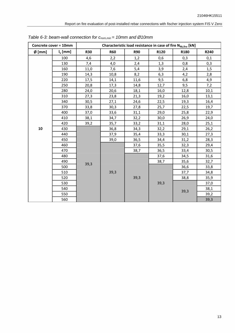
6.2.1. Maximum applicable loads for a beam-wall connection with a concrete cover of 10mm
Table 6-2: beam-wall connection for cnom,min = 10mm and Ø8mm
Ø [mm] lv [mm] R30 R60 R90 R120 R180 R240
100 3,8 1,9 1,1 0,5 0,3 0,1
130 6,2 3,4 2,0 1,1 0,7 0,3
160 9,0 6,3 4,5 3,3 2,1 1,3
190 11,6 8,9 6,9 5,3 3,5 2,4
220 14,2 11,5 9,6 7,9 5,7 4,1
250 16,8 14,1 12,2 10,5 7,9 6,0
280 19,4 16,7 14,8 13,1 10,5 8,4
310 22,0 19,3 17,4 15,7 13,1 10,8
340 24,6 21,9 20,0 18,3 15,8 13,5
350 22,8 20,8 19,2 16,6 14,3
360 23,7 21,7 20,0 17,5 15,2
370 24,5 22,6 20,9 18,4 16,1
380 23,4 21,8 19,2 16,9
390 24,3 22,6 20,1 17,8
400 23,5 21,0 18,7
410 24,4 21,8 19,5
420 22,7 20,4
430 23,6 21,3
440 24,4 22,1
450 23,0
460 23,9
470 24,7
480 25,1
Concrete cover = 10mm Characteristic load resistance in case of fire NRk,fire [kN]
25,1
25,1
25,1
25,1
25,1
8
21046HK15511
Report on fire evaluation of post-installed rebar connections with fischer injection system FIS V Zero
13
Table 6-3: beam-wall connection for cnom,min = 10mm and Ø10mm
Ø [mm] lv [mm] R30 R60 R90 R120 R180 R240
100 4,6 2,2 1,2 0,6 0,3 0,1
130 7,4 4,0 2,4 1,3 0,8 0,3
160 11,0 7,6 5,4 3,9 2,4 1,5
190 14,3 10,8 8,2 6,3 4,2 2,8
220 17,5 14,1 11,6 9,5 6,8 4,9
250 20,8 17,3 14,8 12,7 9,5 7,2
280 24,0 20,6 18,1 16,0 12,8 10,1
310 27,3 23,8 21,3 19,2 16,0 13,1
340 30,5 27,1 24,6 22,5 19,3 16,4
370 33,8 30,3 27,8 25,7 22,5 19,7
400 37,0 33,6 31,1 29,0 25,8 22,9
410 38,1 34,7 32,2 30,0 26,9 24,0
420 39,2 35,7 33,2 31,1 28,0 25,1
430 36,8 34,3 32,2 29,1 26,2
440 37,9 35,4 33,3 30,1 27,3
450 39,0 36,5 34,4 31,2 28,3
460 37,6 35,5 32,3 29,4
470 38,7 36,5 33,4 30,5
480 37,6 34,5 31,6
490 38,7 35,6 32,7
500 36,6 33,8
510 37,7 34,8
520 38,8 35,9
530 37,0
540 38,1
550 39,2
560 39,3
39,3
39,3
39,3
39,3
Concrete cover = 10mm Characteristic load resistance in case of fire NRk,fire [kN]
10
39,3

21046HK15511
Report on fire evaluation of post-installed rebar connections with fischer injection system FIS V Zero
14
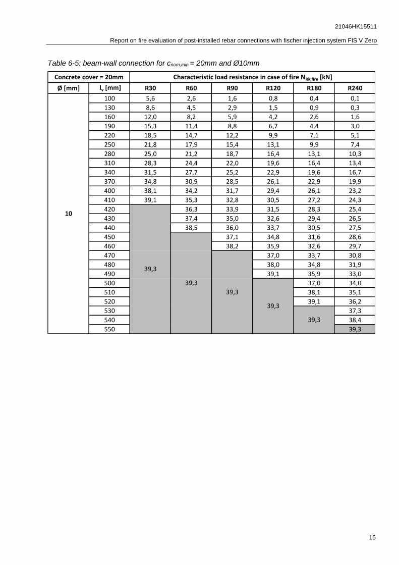
6.2.2. Maximum applicable loads for a beam-wall connection with a concrete cover of 20mm
Table 6-4: beam-wall connection for cnom,min = 20mm and Ø8mm
Ø [mm] lv [mm] R30 R60 R90 R120 R180 R240
100 4,6 2,2 1,3 0,6 0,3 0,1
130 7,0 3,8 2,4 1,3 0,7 0,3
160 9,7 6,8 4,9 3,5 2,2 1,4
190 12,3 9,4 7,3 5,6 3,7 2,5
220 14,9 12,0 10,0 8,2 5,9 4,3
250 17,6 14,6 12,6 10,8 8,2 6,2
280 20,2 17,2 15,2 13,4 10,8 8,5
310 22,8 19,8 17,8 16,0 13,4 11,0
320 23,6 20,6 18,7 16,8 14,3 11,9
330 24,5 21,5 19,6 17,7 15,1 12,8
340 22,4 20,4 18,6 16,0 13,7
350 23,2 21,3 19,4 16,9 14,5
360 24,1 22,2 20,3 17,7 15,4
370 25,0 23,0 21,2 18,6 16,3
380 23,9 22,0 19,5 17,1
390 24,8 22,9 20,3 18,0
400 23,8 21,2 18,9
410 24,6 22,1 19,7
420 22,9 20,6
430 23,8 21,5
440 24,7 22,3
450 23,2
460 24,1
470 24,9
480 25,1
Concrete cover = 20mm Characteristic load resistance in case of fire NRk,fire [kN]
8
25,1
25,1
25,1
25,1
25,1
21046HK15511
Report on fire evaluation of post-installed rebar connections with fischer injection system FIS V Zero
15
Table 6-5: beam-wall connection for cnom,min = 20mm and Ø10mm
Ø [mm] lv [mm] R30 R60 R90 R120 R180 R240
100 5,6 2,6 1,6 0,8 0,4 0,1
130 8,6 4,5 2,9 1,5 0,9 0,3
160 12,0 8,2 5,9 4,2 2,6 1,6
190 15,3 11,4 8,8 6,7 4,4 3,0
220 18,5 14,7 12,2 9,9 7,1 5,1
250 21,8 17,9 15,4 13,1 9,9 7,4
280 25,0 21,2 18,7 16,4 13,1 10,3
310 28,3 24,4 22,0 19,6 16,4 13,4
340 31,5 27,7 25,2 22,9 19,6 16,7
370 34,8 30,9 28,5 26,1 22,9 19,9
400 38,1 34,2 31,7 29,4 26,1 23,2
410 39,1 35,3 32,8 30,5 27,2 24,3
420 36,3 33,9 31,5 28,3 25,4
430 37,4 35,0 32,6 29,4 26,5
440 38,5 36,0 33,7 30,5 27,5
450 37,1 34,8 31,6 28,6
460 38,2 35,9 32,6 29,7
470 37,0 33,7 30,8
480 38,0 34,8 31,9
490 39,1 35,9 33,0
500 37,0 34,0
510 38,1 35,1
520 39,1 36,2
530 37,3
540 38,4
550 39,3
Concrete cover = 20mm Characteristic load resistance in case of fire NRk,fire [kN]
10
39,3
39,3
39,3
39,3
39,3

21046HK15511
Report on fire evaluation of post-installed rebar connections with fischer injection system FIS V Zero
16
Table 6-6: beam-wall connection for cnom,min = 20mm and Ø12mm
Ø [mm] lv [mm] R30 R60 R90 R120 R180 R240
100 6,5 3,2 1,8 0,9 0,5 0,1
130 10,0 5,4 3,3 1,8 1,0 0,4
160 14,3 9,6 6,8 4,8 3,0 1,9
190 18,2 13,5 10,2 7,6 5,1 3,4
220 22,1 17,4 14,2 11,4 8,2 5,9
250 26,0 21,3 18,1 15,3 11,4 8,6
280 29,9 25,2 22,1 19,2 15,3 12,1
310 33,8 29,1 26,0 23,1 19,2 15,6
340 37,7 33,0 29,9 27,0 23,1 19,6
370 41,6 36,9 33,8 30,9 27,0 23,5
400 45,5 40,8 37,7 34,8 30,9 27,4
430 49,4 44,7 41,6 38,7 34,8 31,3
460 53,3 48,6 45,5 42,6 38,7 35,2
470 54,6 49,9 46,8 43,9 40,0 36,5
480 55,9 51,2 48,1 45,2 41,3 37,8
490 52,5 49,4 46,5 42,6 39,1
500 53,8 50,7 47,8 43,9 40,4
510 55,1 52,0 49,1 45,2 41,7
520 56,4 53,3 50,4 46,5 43,0
530 54,6 51,7 47,8 44,3
540 55,9 53,0 49,1 45,6
550 54,3 50,4 46,9
560 55,6 51,7 48,2
570 53,0 49,5
580 54,3 50,8
590 55,6 52,1
600 53,4
610 54,7
620 56,0
630 56,5
Concrete cover = 20mm Characteristic load resistance in case of fire NRk,fire [kN]
12
56,5
56,5
56,5
56,5
56,5

21046HK15511
Report on fire evaluation of post-installed rebar connections with fischer injection system FIS V Zero
17
Table 6-7: beam-wall connection for cnom,min = 20mm and Ø14mm
Ø [mm] lv [mm] R30 R60 R90 R120 R180 R240
140 13,5 8,1 5,4 3,5 2,1 1,2
170 18,1 12,2 8,7 6,2 3,9 2,4
200 22,6 16,9 13,2 10,1 6,9 4,8
230 27,2 21,5 17,7 14,2 10,2 7,4
260 31,7 26,0 22,3 18,9 14,4 11,0
290 36,3 30,6 26,8 23,4 18,7 14,8
320 40,8 35,2 31,4 28,0 23,3 19,3
350 45,4 39,7 35,9 32,5 27,9 23,8
380 49,9 44,3 40,5 37,1 32,4 28,3
410 54,5 48,8 45,0 41,6 37,0 32,9
440 59,0 53,4 49,6 46,2 41,5 37,4
470 63,6 57,9 54,1 50,7 46,1 42,0
500 68,1 62,5 58,7 55,3 50,7 46,5
530 72,7 67,0 63,2 59,8 55,2 51,1
540 74,2 68,5 64,7 61,4 56,7 52,6
550 75,7 70,1 66,3 62,9 58,2 54,1
560 71,6 67,8 64,4 59,8 55,7
570 73,1 69,3 65,9 61,3 57,2
580 74,6 70,8 67,4 62,8 58,7
590 76,1 72,3 68,9 64,3 60,2
600 73,8 70,5 65,8 61,7
610 75,4 72,0 67,3 63,2
620 76,9 73,5 68,9 64,8
630 75,0 70,4 66,3
640 76,5 71,9 67,8
650 73,4 69,3
660 74,9 70,8
670 76,4 72,3
680 73,9
690 75,4
700 76,9
710 77,0
Concrete cover = 20mm Characteristic load resistance in case of fire NRk,fire [kN]
14
77,0
77,0
77,0
77,0
77,0

21046HK15511
Report on fire evaluation of post-installed rebar connections with fischer injection system FIS V Zero
18
Table 6-8: beam-wall connection for cnom,min = 20mm and Ø16mm
Ø [mm] lv [mm] R30 R60 R90 R120 R180 R240
160 18,8 12,1 8,4 5,9 3,6 2,2
190 24,0 17,1 12,7 9,4 6,2 4,1
220 29,2 22,4 17,9 14,2 10,0 7,2
250 34,4 27,6 23,1 19,2 14,1 10,6
280 39,6 32,8 28,3 24,5 19,1 15,0
310 44,8 38,0 33,5 29,7 24,2 19,5
340 50,0 43,2 38,7 34,9 29,5 24,7
370 55,2 48,4 43,9 40,1 34,7 29,9
400 60,4 53,6 49,1 45,3 39,9 35,2
430 65,7 58,8 54,3 50,5 45,1 40,4
460 70,9 64,0 59,5 55,7 50,3 45,6
490 76,1 69,2 64,7 60,9 55,5 50,8
520 81,3 74,4 69,9 66,1 60,7 56,0
550 86,5 79,6 75,2 71,3 65,9 61,2
580 91,7 84,9 80,4 76,5 71,1 66,4
610 96,9 90,1 85,6 81,7 76,3 71,6
620 98,6 91,8 87,3 83,5 78,0 73,3
630 100,3 93,5 89,0 85,2 79,8 75,0
640 95,3 90,8 86,9 81,5 76,8
650 97,0 92,5 88,7 83,2 78,5
660 98,7 94,2 90,4 85,0 80,2
670 96,0 92,1 86,7 82,0
680 97,7 93,9 88,4 83,7
690 99,4 95,6 90,2 85,4
700 97,3 91,9 87,2
710 99,1 93,6 88,9
720 95,4 90,6
730 97,1 92,4
740 98,8 94,1
750 95,8
760 97,6
770 99,3
780 100,5
Concrete cover = 20mm Characteristic load resistance in case of fire NRk,fire [kN]
16
100,5
100,5
100,5
100,5
100,5

21046HK15511
Report on fire evaluation of post-installed rebar connections with fischer injection system FIS V Zero
19
Table 6-9: beam-wall connection for cnom,min = 20mm and Ø20mm
Ø [mm] lv [mm] R30 R60 R90 R120 R180 R240
200 31,9 22,7 17,0 12,9 8,7 6,0
230 38,4 29,2 23,2 18,3 12,9 9,3
260 44,9 35,7 29,8 24,8 18,5 14,1
290 51,4 42,3 36,3 31,3 24,3 19,1
320 57,9 48,8 42,8 37,8 30,9 25,1
350 64,4 55,3 49,3 44,3 37,4 31,4
380 70,9 61,8 55,8 50,8 43,9 38,0
410 77,4 68,3 62,3 57,3 50,4 44,5
440 83,9 74,8 68,8 63,8 56,9 51,0
470 90,4 81,3 75,4 70,4 63,4 57,5
500 96,9 87,8 81,9 76,9 69,9 64,0
530 103,4 94,3 88,4 83,4 76,4 70,5
560 109,9 100,8 94,9 89,9 82,9 77,0
590 116,4 107,3 101,4 96,4 89,4 83,5
620 122,9 113,8 107,9 102,9 95,9 90,0
650 129,4 120,3 114,4 109,4 102,5 96,5
680 135,9 126,8 120,9 115,9 109,0 103,0
710 142,5 133,3 127,4 122,4 115,5 109,5
740 149,0 139,8 133,9 128,9 122,0 116,0
770 155,5 146,3 140,4 135,4 128,5 122,5
780 148,5 142,6 137,5 130,6 124,7
790 150,6 144,7 139,7 132,8 126,8
800 152,8 146,9 141,9 135,0 129,0
810 155,0 149,1 144,1 137,1 131,2
820 151,2 146,2 139,3 133,3
830 153,4 148,4 141,5 135,5
840 155,6 150,6 143,6 137,7
850 152,7 145,8 139,8
860 154,9 148,0 142,0
870 150,1 144,2
880 152,3 146,4
890 154,5 148,5
900 156,6 150,7
910 152,9
920 155,0
930 157,1
Concrete cover = 20mm Characteristic load resistance in case of fire NRk,fire [kN]
20
157,1
157,1
157,1
157,1
157,1

21046HK15511
Report on fire evaluation of post-installed rebar connections with fischer injection system FIS V Zero
20
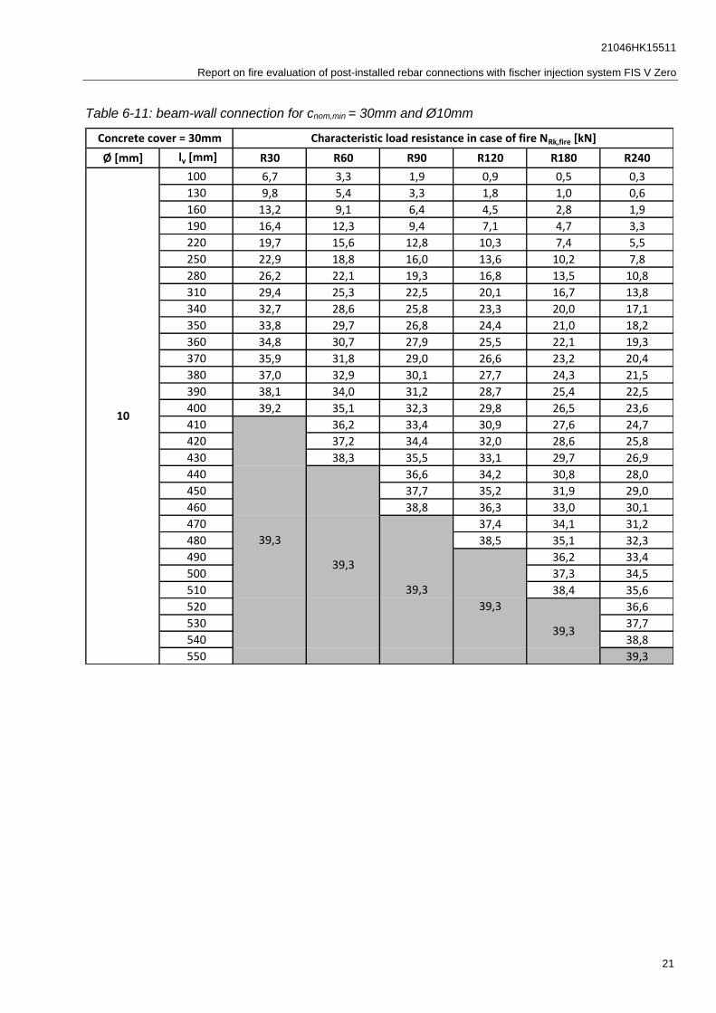
6.2.3. Maximum applicable loads for a beam-wall connection with a concrete cover of 30mm
Table 6-10: beam-wall connection for cnom,min = 30mm and Ø8mm
Ø [mm] lv [mm] R30 R60 R90 R120 R180 R240
100 5,3 2,7 1,6 0,7 0,4 0,2
130 7,8 4,4 2,7 1,5 0,8 0,5
160 10,5 7,4 5,3 3,8 2,4 1,6
190 13,1 10,0 7,8 5,9 3,9 2,8
220 15,7 12,6 10,5 8,5 6,1 4,6
250 18,3 15,2 13,1 11,1 8,4 6,5
280 20,9 17,8 15,7 13,7 11,1 8,9
310 23,5 20,4 18,3 16,3 13,7 11,4
320 24,4 21,3 19,1 17,2 14,5 12,3
330 22,1 20,0 18,0 15,4 13,1
340 23,0 20,9 18,9 16,3 14,0
350 23,9 21,7 19,8 17,2 14,9
360 24,7 22,6 20,6 18,0 15,7
370 23,5 21,5 18,9 16,6
380 24,3 22,4 19,8 17,5
390 23,2 20,6 18,3
400 24,1 21,5 19,2
410 25,0 22,4 20,1
420 23,2 20,9
430 24,1 21,8
440 25,0 22,7
450 23,5
460 24,4
470 25,1
Concrete cover = 30mm Characteristic load resistance in case of fire NRk,fire [kN]
8
25,1
25,1
25,1
25,1
25,1
21046HK15511
Report on fire evaluation of post-installed rebar connections with fischer injection system FIS V Zero
21
Table 6-11: beam-wall connection for cnom,min = 30mm and Ø10mm
Ø [mm] lv [mm] R30 R60 R90 R120 R180 R240
100 6,7 3,3 1,9 0,9 0,5 0,3
130 9,8 5,4 3,3 1,8 1,0 0,6
160 13,2 9,1 6,4 4,5 2,8 1,9
190 16,4 12,3 9,4 7,1 4,7 3,3
220 19,7 15,6 12,8 10,3 7,4 5,5
250 22,9 18,8 16,0 13,6 10,2 7,8
280 26,2 22,1 19,3 16,8 13,5 10,8
310 29,4 25,3 22,5 20,1 16,7 13,8
340 32,7 28,6 25,8 23,3 20,0 17,1
350 33,8 29,7 26,8 24,4 21,0 18,2
360 34,8 30,7 27,9 25,5 22,1 19,3
370 35,9 31,8 29,0 26,6 23,2 20,4
380 37,0 32,9 30,1 27,7 24,3 21,5
390 38,1 34,0 31,2 28,7 25,4 22,5
400 39,2 35,1 32,3 29,8 26,5 23,6
410 36,2 33,4 30,9 27,6 24,7
420 37,2 34,4 32,0 28,6 25,8
430 38,3 35,5 33,1 29,7 26,9
440 36,6 34,2 30,8 28,0
450 37,7 35,2 31,9 29,0
460 38,8 36,3 33,0 30,1
470 37,4 34,1 31,2
480 38,5 35,1 32,3
490 36,2 33,4
500 37,3 34,5
510 38,4 35,6
520 36,6
530 37,7
540 38,8
550 39,3
Concrete cover = 30mm Characteristic load resistance in case of fire NRk,fire [kN]
39,3
39,3
39,3
39,3
39,3
10
21046HK15511
Report on fire evaluation of post-installed rebar connections with fischer injection system FIS V Zero
22
Table 6-12: beam-wall connection for cnom,min = 30mm and Ø12mm
Ø [mm] lv [mm] R30 R60 R90 R120 R180 R240
100 7,9 3,9 2,2 1,0 0,5 0,3
130 11,7 6,3 3,9 2,1 1,2 0,7
160 15,7 10,6 7,5 5,2 3,3 2,2
190 19,6 14,5 11,0 8,2 5,4 3,8
220 23,5 18,4 15,0 12,0 8,5 6,3
250 27,4 22,3 18,9 15,9 11,8 9,1
280 31,3 26,2 22,8 19,8 15,7 12,5
310 35,2 30,1 26,7 23,7 19,6 16,1
340 39,1 34,0 30,6 27,6 23,5 20,1
370 43,0 37,9 34,5 31,5 27,4 24,0
400 46,9 41,8 38,4 35,4 31,3 27,9
430 50,9 45,7 42,3 39,3 35,2 31,8
460 54,8 49,6 46,2 43,2 39,1 35,7
470 56,1 50,9 47,5 44,5 40,4 37,0
480 52,2 48,8 45,8 41,7 38,3
490 53,5 50,1 47,1 43,0 39,6
500 54,8 51,4 48,4 44,3 40,9
510 56,1 52,7 49,7 45,6 42,2
520 54,0 51,0 46,9 43,5
530 55,3 52,3 48,2 44,8
540 53,6 49,6 46,1
550 54,9 50,9 47,4
560 56,2 52,2 48,7
570 53,5 50,0
580 54,8 51,3
590 56,1 52,6
600 53,9
610 55,2
620 56,5
Concrete cover = 30mm Characteristic load resistance in case of fire NRk,fire [kN]
12
56,5
56,5
56,5
56,5
56,5
21046HK15511
Report on fire evaluation of post-installed rebar connections with fischer injection system FIS V Zero
23
Table 6-13: beam-wall connection for cnom,min = 30mm and Ø14mm
Ø [mm] lv [mm] R30 R60 R90 R120 R180 R240
140 15,2 9,3 6,1 3,9 2,3 1,5
170 19,8 13,5 9,6 6,8 4,2 2,9
200 24,3 18,2 14,1 10,7 7,3 5,3
230 28,9 22,7 18,6 14,9 10,7 8,0
260 33,4 27,3 23,2 19,6 14,9 11,6
290 38,0 31,8 27,7 24,1 19,3 15,4
320 42,5 36,4 32,3 28,7 23,9 19,9
350 47,1 40,9 36,8 33,2 28,5 24,5
380 51,7 45,5 41,4 37,8 33,0 29,0
410 56,2 50,0 45,9 42,3 37,6 33,6
440 60,8 54,6 50,5 46,9 42,2 38,1
470 65,3 59,2 55,0 51,5 46,7 42,7
500 69,9 63,7 59,6 56,0 51,3 47,2
530 74,4 68,3 64,1 60,6 55,8 51,8
540 75,9 69,8 65,6 62,1 57,3 53,3
550 71,3 67,2 63,6 58,8 54,8
560 72,8 68,7 65,1 60,4 56,3
570 74,3 70,2 66,6 61,9 57,8
580 75,8 71,7 68,1 63,4 59,4
590 73,2 69,7 64,9 60,9
600 74,8 71,2 66,4 62,4
610 76,3 72,7 67,9 63,9
620 74,2 69,5 65,4
630 75,7 71,0 66,9
640 72,5 68,5
650 74,0 70,0
660 75,5 71,5
670 73,0
680 74,5
690 76,1
700 77,0
Concrete cover = 30mm Characteristic load resistance in case of fire NRk,fire [kN]
14
77,0
77,0
77,0
77,0
77,0
21046HK15511
Report on fire evaluation of post-installed rebar connections with fischer injection system FIS V Zero
24
Table 6-14: beam-wall connection for cnom,min = 30mm and Ø16mm
Ø [mm] lv [mm] R30 R60 R90 R120 R180 R240
160 20,8 13,7 9,3 6,7 4,0 2,7
190 26,0 18,8 13,7 10,4 6,7 4,7
220 31,2 24,0 19,0 15,2 10,6 7,8
250 36,4 29,2 24,2 20,3 14,8 11,3
280 41,6 34,4 29,4 25,6 19,8 15,7
310 46,8 39,6 34,6 30,8 25,0 20,4
340 52,0 44,8 39,8 36,0 30,2 25,6
370 57,2 50,0 45,0 41,2 35,4 30,8
400 62,4 55,2 50,2 46,4 40,6 36,0
430 67,6 60,4 55,4 51,6 45,8 41,2
460 72,8 65,6 60,6 56,8 51,0 46,4
490 78,0 70,8 65,8 62,0 56,2 51,6
520 83,2 76,0 71,0 67,2 61,4 56,8
550 88,4 81,2 76,2 72,4 66,6 62,0
580 93,6 86,4 81,4 77,6 71,8 67,2
610 98,8 91,6 86,6 82,8 77,1 72,4
620 93,4 88,4 84,5 78,8 74,2
630 95,1 90,1 86,3 80,5 75,9
640 96,8 91,8 88,0 82,3 77,6
650 98,6 93,6 89,7 84,0 79,4
660 100,3 95,3 91,5 85,7 81,1
670 97,1 93,2 87,5 82,8
680 98,8 94,9 89,2 84,6
690 96,7 90,9 86,3
700 98,4 92,7 88,0
710 100,1 94,4 89,8
720 96,1 91,5
730 97,9 93,2
740 99,6 95,0
750 96,7
760 98,5
770 100,2
780 100,5
Concrete cover = 30mm Characteristic load resistance in case of fire NRk,fire [kN]
16
100,5
100,5
100,5
100,5
100,5

21046HK15511
Report on fire evaluation of post-installed rebar connections with fischer injection system FIS V Zero
25
Table 6-15: beam-wall connection for cnom,min = 30mm and Ø20mm
Ø [mm] lv [mm] R30 R60 R90 R120 R180 R240
200 34,8 25,2 18,7 14,3 9,5 6,7
230 41,3 31,7 25,0 19,9 13,9 10,2
260 47,8 38,2 31,6 26,5 19,5 15,0
290 54,3 44,7 38,1 33,0 25,4 20,2
320 60,8 51,2 44,6 39,5 32,1 26,2
350 67,3 57,8 51,1 46,0 38,6 32,5
380 73,8 64,3 57,6 52,5 45,1 39,1
410 80,3 70,8 64,1 59,0 51,6 45,6
440 86,8 77,3 70,6 65,5 58,1 52,1
470 93,3 83,8 77,1 72,0 64,6 58,6
500 99,8 90,3 83,6 78,5 71,1 65,1
530 106,3 96,8 90,1 85,0 77,6 71,6
560 112,8 103,3 96,6 91,5 84,1 78,1
590 119,3 109,8 103,1 98,0 90,6 84,7
620 125,8 116,3 109,6 104,5 97,1 91,2
650 132,3 122,8 116,1 111,0 103,6 97,7
680 138,8 129,3 122,6 117,5 110,1 104,2
710 145,3 135,8 129,2 124,0 116,6 110,7
740 151,8 142,3 135,7 130,5 123,1 117,2
750 154,0 144,5 137,8 132,7 125,3 119,3
760 156,2 146,6 140,0 134,9 127,4 121,5
770 148,8 142,2 137,0 129,6 123,7
780 151,0 144,3 139,2 131,8 125,8
790 153,1 146,5 141,4 133,9 128,0
800 155,3 148,7 143,5 136,1 130,2
810 150,8 145,7 138,3 132,3
820 153,0 147,9 140,4 134,5
830 155,2 150,0 142,6 136,7
840 152,2 144,8 138,8
850 154,4 147,0 141,0
860 156,5 149,1 143,2
870 151,3 145,3
880 153,5 147,5
890 155,6 149,7
900 151,8
910 154,0
920 156,2
930 157,1
Concrete cover = 30mm Characteristic load resistance in case of fire NRk,fire [kN]
20
157,1
157,1
157,1
157,1
157,1
21046HK15511
Report on fire evaluation of post-installed rebar connections with fischer injection system FIS V Zero
26
Table 6-16: beam-wall connection for cnom,min = 30mm and Ø22mm
Ø [mm] lv [mm] R30 R60 R90 R120 R180 R240
200 34,8 25,2 18,7 14,3 9,5 6,7
230 41,3 31,7 25,0 19,9 13,9 10,2
260 47,8 38,2 31,6 26,5 19,5 15,0
290 54,3 44,7 38,1 33,0 25,4 20,2
320 60,8 51,2 44,6 39,5 32,1 26,2
350 67,3 57,8 51,1 46,0 38,6 32,5
380 73,8 64,3 57,6 52,5 45,1 39,1
410 80,3 70,8 64,1 59,0 51,6 45,6
440 86,8 77,3 70,6 65,5 58,1 52,1
470 93,3 83,8 77,1 72,0 64,6 58,6
500 99,8 90,3 83,6 78,5 71,1 65,1
530 106,3 96,8 90,1 85,0 77,6 71,6
560 112,8 103,3 96,6 91,5 84,1 78,1
590 119,3 109,8 103,1 98,0 90,6 84,7
620 125,8 116,3 109,6 104,5 97,1 91,2
650 132,3 122,8 116,1 111,0 103,6 97,7
680 138,8 129,3 122,6 117,5 110,1 104,2
710 145,3 135,8 129,2 124,0 116,6 110,7
740 151,8 142,3 135,7 130,5 123,1 117,2
750 154,0 144,5 137,8 132,7 125,3 119,3
760 156,2 146,6 140,0 134,9 127,4 121,5
770 148,8 142,2 137,0 129,6 123,7
780 151,0 144,3 139,2 131,8 125,8
790 153,1 146,5 141,4 133,9 128,0
800 155,3 148,7 143,5 136,1 130,2
810 150,8 145,7 138,3 132,3
820 153,0 147,9 140,4 134,5
830 155,2 150,0 142,6 136,7
840 152,2 144,8 138,8
850 154,4 147,0 141,0
860 156,5 149,1 143,2
870 151,3 145,3
880 153,5 147,5
890 155,6 149,7
900 151,8
910 154,0
920 156,2
930 157,1
Concrete cover = 30mm Characteristic load resistance in case of fire NRk,fire [kN]
22
157,1
157,1
157,1
157,1
157,1

21046HK15511
Report on fire evaluation of post-installed rebar connections with fischer injection system FIS V Zero
27
Table 6-17: beam-wall connection for cnom,min = 30mm and Ø24mm
Ø [mm] lv [mm] R30 R60 R90 R120 R180 R240
200 34,8 25,2 18,7 14,3 9,5 6,7
230 41,3 31,7 25,0 19,9 13,9 10,2
260 47,8 38,2 31,6 26,5 19,5 15,0
290 54,3 44,7 38,1 33,0 25,4 20,2
320 60,8 51,2 44,6 39,5 32,1 26,2
350 67,3 57,8 51,1 46,0 38,6 32,5
380 73,8 64,3 57,6 52,5 45,1 39,1
410 80,3 70,8 64,1 59,0 51,6 45,6
440 86,8 77,3 70,6 65,5 58,1 52,1
470 93,3 83,8 77,1 72,0 64,6 58,6
500 99,8 90,3 83,6 78,5 71,1 65,1
530 106,3 96,8 90,1 85,0 77,6 71,6
560 112,8 103,3 96,6 91,5 84,1 78,1
590 119,3 109,8 103,1 98,0 90,6 84,7
620 125,8 116,3 109,6 104,5 97,1 91,2
650 132,3 122,8 116,1 111,0 103,6 97,7
680 138,8 129,3 122,6 117,5 110,1 104,2
710 145,3 135,8 129,2 124,0 116,6 110,7
740 151,8 142,3 135,7 130,5 123,1 117,2
750 154,0 144,5 137,8 132,7 125,3 119,3
760 156,2 146,6 140,0 134,9 127,4 121,5
770 148,8 142,2 137,0 129,6 123,7
780 151,0 144,3 139,2 131,8 125,8
790 153,1 146,5 141,4 133,9 128,0
800 155,3 148,7 143,5 136,1 130,2
810 150,8 145,7 138,3 132,3
820 153,0 147,9 140,4 134,5
830 155,2 150,0 142,6 136,7
840 152,2 144,8 138,8
850 154,4 147,0 141,0
860 156,5 149,1 143,2
870 151,3 145,3
880 153,5 147,5
890 155,6 149,7
900 151,8
910 154,0
920 156,2
930 157,1
Concrete cover = 30mm Characteristic load resistance in case of fire NRk,fire [kN]
24
157,1
157,1
157,1
157,1
157,1
21046HK15511
Report on fire evaluation of post-installed rebar connections with fischer injection system FIS V Zero
28
Table 6-18: beam-wall connection for cnom,min = 30mm and Ø25mm
Ø [mm] lv [mm] R30 R60 R90 R120 R180 R240
250 57,2 44,3 35,5 28,5 20,2 14,9
280 65,4 52,4 43,8 36,8 27,4 21,1
310 73,5 60,5 51,9 44,9 34,9 27,7
340 81,6 68,6 60,0 53,0 43,3 35,4
370 89,7 76,8 68,1 61,1 51,4 43,3
400 97,9 84,9 76,3 69,3 59,5 51,5
430 106,0 93,0 84,4 77,4 67,6 59,7
460 114,1 101,2 92,5 85,5 75,8 67,8
490 122,3 109,3 100,7 93,7 83,9 75,9
520 130,4 117,4 108,8 101,8 92,0 84,0
550 138,5 125,5 116,9 109,9 100,2 92,2
580 146,6 133,7 125,0 118,0 108,3 100,3
610 154,8 141,8 133,2 126,2 116,4 108,4
640 162,9 149,9 141,3 134,3 124,5 116,6
670 171,0 158,1 149,4 142,4 132,7 124,7
700 179,2 166,2 157,6 150,6 140,8 132,8
730 187,3 174,3 165,7 158,7 148,9 141,0
760 195,4 182,4 173,8 166,8 157,1 149,1
790 203,5 190,6 181,9 175,0 165,2 157,2
820 211,7 198,7 190,1 183,1 173,3 165,3
850 219,8 206,8 198,2 191,2 181,4 173,5
880 227,9 215,0 206,3 199,3 189,6 181,6
910 236,1 223,1 214,5 207,5 197,7 189,7
940 244,2 231,2 222,6 215,6 205,8 197,9
950 233,9 225,3 218,3 208,5 200,6
960 236,6 228,0 221,0 211,3 203,3
970 239,3 230,7 223,7 214,0 206,0
990 244,8 236,1 229,1 219,4 211,4
1010 241,6 234,6 224,8 216,8
1050 235,6 227,7
1070 241,1 233,1
1090 238,5
1110 243,9
1230 245,4
Concrete cover = 30mm Characteristic load resistance in case of fire NRk,fire [kN]
25
245,4
245,4245,4 245,4
245,4

21046HK15511
Report on fire evaluation of post-installed rebar connections with fischer injection system FIS V Zero
29
6.2.4. Maximum applicable loads for a beam-wall connection with a concrete cover of 40mm
Table 6-19: beam-wall connection for cnom,min = 40mm and Ø8mm
Ø [mm] lv [mm] R30 R60 R90 R120 R180 R240
100 6,2 3,3 2,0 1,0 0,6 0,3
130 8,7 5,1 3,3 1,8 1,1 0,6
160 11,4 8,1 5,9 4,2 2,7 1,7
190 14,0 10,7 8,4 6,3 4,3 2,9
220 16,6 13,3 11,0 9,0 6,5 4,8
250 19,2 15,9 13,6 11,6 8,8 6,7
280 21,8 18,5 16,3 14,2 11,5 9,1
310 24,4 21,1 18,9 16,8 14,1 11,7
320 22,0 19,7 17,6 15,0 12,6
330 22,8 20,6 18,5 15,8 13,4
340 23,7 21,5 19,4 16,7 14,3
350 24,6 22,3 20,2 17,6 15,2
360 23,2 21,1 18,4 16,0
370 24,1 22,0 19,3 16,9
380 24,9 22,8 20,2 17,8
390 23,7 21,0 18,6
400 24,6 21,9 19,5
410 22,8 20,4
420 23,6 21,2
430 24,5 22,1
440 23,0
450 23,8
460 24,7
470 25,1
Concrete cover = 40mm Characteristic load resistance in case of fire NRk,fire [kN]
8
25,1
25,1
25,1
25,1
25,1
21046HK15511
Report on fire evaluation of post-installed rebar connections with fischer injection system FIS V Zero
30
Table 6-20: beam-wall connection for cnom,min = 40mm and Ø10mm
Ø [mm] lv [mm] R30 R60 R90 R120 R180 R240
100 7,7 4,1 2,4 1,2 0,7 0,3
130 10,9 6,4 4,0 2,2 1,3 0,7
160 14,2 10,0 7,2 5,1 3,2 2,1
190 17,5 13,3 10,2 7,7 5,2 3,5
220 20,7 16,5 13,6 11,0 7,9 5,8
250 24,0 19,8 16,8 14,2 10,8 8,2
280 27,2 23,0 20,1 17,5 14,1 11,1
310 30,5 26,3 23,3 20,7 17,3 14,2
340 33,7 29,5 26,6 24,0 20,6 17,5
370 37,0 32,8 29,8 27,2 23,8 20,8
380 38,1 33,9 30,9 28,3 24,9 21,8
390 39,1 34,9 32,0 29,4 26,0 22,9
400 36,0 33,1 30,5 27,1 24,0
410 37,1 34,2 31,5 28,2 25,1
420 38,2 35,3 32,6 29,2 26,2
430 36,3 33,7 30,3 27,3
440 37,4 34,8 31,4 28,4
450 38,5 35,9 32,5 29,4
460 37,0 33,6 30,5
470 38,0 34,7 31,6
480 39,1 35,7 32,7
490 36,8 33,8
500 37,9 34,9
510 39,0 35,9
520 37,0
530 38,1
540 39,2
550 39,3
Concrete cover = 40mm Characteristic load resistance in case of fire NRk,fire [kN]
10
39,3
39,3
39,3
39,3
39,3
21046HK15511
Report on fire evaluation of post-installed rebar connections with fischer injection system FIS V Zero
31
Table 6-21: beam-wall connection for cnom,min = 40mm and Ø12mm
Ø [mm] lv [mm] R30 R60 R90 R120 R180 R240
100 9,3 4,9 2,9 1,5 0,8 0,4
130 13,1 7,5 4,7 2,6 1,6 0,8
160 17,1 11,9 8,5 5,9 3,8 2,4
190 21,0 15,8 12,0 9,0 6,0 4,1
220 24,9 19,7 16,1 12,8 9,2 6,7
250 28,8 23,6 20,0 16,7 12,6 9,5
280 32,7 27,5 23,9 20,7 16,5 13,0
310 36,6 31,4 27,8 24,6 20,4 16,6
340 40,5 35,3 31,7 28,5 24,3 20,6
370 44,4 39,2 35,6 32,4 28,2 24,5
400 48,3 43,1 39,5 36,3 32,1 28,4
430 52,2 47,0 43,4 40,2 36,0 32,3
460 56,1 50,9 47,3 44,1 39,9 36,2
470 52,2 48,6 45,4 41,2 37,5
480 53,5 49,9 46,7 42,5 38,8
490 54,8 51,2 48,0 43,8 40,1
500 56,1 52,5 49,3 45,1 41,4
510 53,8 50,6 46,4 42,7
520 55,1 51,9 47,7 44,0
530 56,4 53,2 49,0 45,3
540 54,5 50,3 46,6
550 55,8 51,6 47,9
560 52,9 49,2
570 54,2 50,5
580 55,5 51,8
590 53,1
600 54,4
610 55,7
620 56,5
Concrete cover = 40mm Characteristic load resistance in case of fire NRk,fire [kN]
56,5
56,5
56,5
56,5
56,5
12

21046HK15511
Report on fire evaluation of post-installed rebar connections with fischer injection system FIS V Zero
32
Table 6-22: beam-wall connection for cnom,min = 40mm and Ø14mm
Ø [mm] lv [mm] R30 R60 R90 R120 R180 R240
140 17,0 10,7 7,2 4,7 2,8 1,7
170 21,5 15,1 10,8 7,7 4,9 3,1
200 26,1 19,8 15,4 11,7 8,1 5,6
230 30,6 24,3 19,9 16,0 11,5 8,4
260 35,2 28,9 24,5 20,7 15,8 12,1
290 39,7 33,4 29,0 25,2 20,2 16,0
320 44,3 38,0 33,6 29,8 24,9 20,5
350 48,8 42,5 38,1 34,3 29,4 25,1
380 53,4 47,1 42,7 38,9 34,0 29,6
410 57,9 51,6 47,2 43,4 38,5 34,2
440 62,5 56,2 51,8 48,0 43,1 38,7
470 67,0 60,7 56,3 52,5 47,6 43,3
500 71,6 65,3 60,9 57,1 52,2 47,8
530 76,1 69,8 65,4 61,7 56,7 52,4
540 71,3 67,0 63,2 58,3 53,9
550 72,9 68,5 64,7 59,8 55,4
560 74,4 70,0 66,2 61,3 56,9
570 75,9 71,5 67,7 62,8 58,4
580 73,0 69,2 64,3 60,0
590 74,5 70,8 65,8 61,5
600 76,1 72,3 67,4 63,0
610 73,8 68,9 64,5
620 75,3 70,4 66,0
630 76,8 71,9 67,6
640 73,4 69,1
650 74,9 70,6
660 76,5 72,1
670 73,6
680 75,1
690 76,7
700 77,0
Concrete cover = 40mm Characteristic load resistance in case of fire NRk,fire [kN]
14
77,0
77,0
77,0
77,0
77,0

21046HK15511
Report on fire evaluation of post-installed rebar connections with fischer injection system FIS V Zero
33
Table 6-23: beam-wall connection for cnom,min = 40mm and Ø16mm
Ø [mm] lv [mm] R30 R60 R90 R120 R180 R240
160 22,9 15,4 10,8 7,5 4,7 3,0
190 28,1 20,7 15,4 11,4 7,5 5,1
220 33,3 25,8 20,8 16,3 11,6 8,3
250 38,5 31,0 26,0 21,4 15,8 11,9
280 43,7 36,3 31,2 26,7 20,9 16,4
310 48,9 41,5 36,4 31,9 26,1 21,1
340 54,1 46,7 41,6 37,1 31,4 26,4
370 59,3 51,9 46,8 42,3 36,6 31,6
400 64,5 57,1 52,0 47,5 41,8 36,8
430 69,7 62,3 57,2 52,7 47,0 42,0
460 74,9 67,5 62,4 57,9 52,2 47,2
490 80,1 72,7 67,6 63,1 57,4 52,4
520 85,3 77,9 72,8 68,3 62,6 57,6
550 90,5 83,1 78,0 73,5 67,8 62,8
580 95,7 88,3 83,2 78,7 73,0 68,0
590 97,5 90,0 84,9 80,4 74,7 69,7
600 99,2 91,7 86,6 82,2 76,4 71,5
610 93,5 88,4 83,9 78,2 73,2
620 95,2 90,1 85,6 79,9 74,9
630 96,9 91,9 87,4 81,6 76,7
640 98,7 93,6 89,1 83,4 78,4
650 100,4 95,3 90,8 85,1 80,1
660 97,1 92,6 86,8 81,9
670 98,8 94,3 88,6 83,6
680 96,0 90,3 85,3
690 97,8 92,0 87,1
700 99,5 93,8 88,8
710 95,5 90,5
720 97,2 92,3
730 99,0 94,0
740 95,7
750 97,5
760 99,2
770 100,5
100,5
Concrete cover = 40mm Characteristic load resistance in case of fire NRk,fire [kN]
16
100,5
100,5
100,5
100,5

21046HK15511
Report on fire evaluation of post-installed rebar connections with fischer injection system FIS V Zero
34
Table 6-24: beam-wall connection for cnom,min = 40mm and Ø20mm
Ø [mm] lv [mm] R30 R60 R90 R120 R180 R240
200 37,5 27,7 20,9 15,7 10,6 7,4
230 44,0 34,2 27,3 21,5 15,2 11,0
260 50,5 40,7 33,9 28,1 21,0 15,9
290 57,0 47,2 40,4 34,6 27,0 21,1
320 63,5 53,7 46,9 41,1 33,6 27,3
350 70,0 60,2 53,4 47,6 40,1 33,6
380 76,5 66,7 59,9 54,1 46,6 40,2
410 83,0 73,2 66,4 60,6 53,1 46,7
440 89,5 79,7 72,9 67,1 59,6 53,2
470 96,0 86,2 79,4 73,7 66,1 59,7
500 102,5 92,7 85,9 80,2 72,6 66,2
530 109,0 99,2 92,4 86,7 79,1 72,7
560 115,5 105,7 98,9 93,2 85,6 79,2
590 122,0 112,2 105,4 99,7 92,1 85,7
620 128,5 118,8 111,9 106,2 98,7 92,2
650 135,0 125,3 118,4 112,7 105,2 98,7
680 141,5 131,8 124,9 119,2 111,7 105,2
710 148,0 138,3 131,4 125,7 118,2 111,7
740 154,5 144,8 137,9 132,2 124,7 118,2
750 156,7 146,9 140,1 134,3 126,8 120,4
760 149,1 142,3 136,5 129,0 122,6
770 151,3 144,4 138,7 131,2 124,7
780 153,4 146,6 140,9 133,3 126,9
790 155,6 148,8 143,0 135,5 129,1
800 150,9 145,2 137,7 131,2
810 153,1 147,4 139,8 133,4
820 155,3 149,5 142,0 135,6
830 151,7 144,2 137,7
840 153,9 146,3 139,9
850 156,0 148,5 142,1
860 150,7 144,2
870 152,8 146,4
880 155,0 148,6
890 150,7
900 152,9
910 155,1
920 157,1
157,1
Concrete cover = 40mm Characteristic load resistance in case of fire NRk,fire [kN]
20
157,1
157,1
157,1
157,1

21046HK15511
Report on fire evaluation of post-installed rebar connections with fischer injection system FIS V Zero
35
Table 6-25: beam-wall connection for cnom,min = 40mm and Ø22mm
Ø [mm] lv [mm] R30 R60 R90 R120 R180 R240
200 37,5 27,7 20,9 15,7 10,6 7,4
230 44,0 34,2 27,3 21,5 15,2 11,0
260 50,5 40,7 33,9 28,1 21,0 15,9
290 57,0 47,2 40,4 34,6 27,0 21,1
320 63,5 53,7 46,9 41,1 33,6 27,3
350 70,0 60,2 53,4 47,6 40,1 33,6
380 76,5 66,7 59,9 54,1 46,6 40,2
410 83,0 73,2 66,4 60,6 53,1 46,7
440 89,5 79,7 72,9 67,1 59,6 53,2
470 96,0 86,2 79,4 73,7 66,1 59,7
500 102,5 92,7 85,9 80,2 72,6 66,2
530 109,0 99,2 92,4 86,7 79,1 72,7
560 115,5 105,7 98,9 93,2 85,6 79,2
590 122,0 112,2 105,4 99,7 92,1 85,7
620 128,5 118,8 111,9 106,2 98,7 92,2
650 135,0 125,3 118,4 112,7 105,2 98,7
680 141,5 131,8 124,9 119,2 111,7 105,2
710 148,0 138,3 131,4 125,7 118,2 111,7
740 154,5 144,8 137,9 132,2 124,7 118,2
750 156,7 146,9 140,1 134,3 126,8 120,4
760 149,1 142,3 136,5 129,0 122,6
770 151,3 144,4 138,7 131,2 124,7
780 153,4 146,6 140,9 133,3 126,9
790 155,6 148,8 143,0 135,5 129,1
800 150,9 145,2 137,7 131,2
810 153,1 147,4 139,8 133,4
820 155,3 149,5 142,0 135,6
830 151,7 144,2 137,7
840 153,9 146,3 139,9
850 156,0 148,5 142,1
860 150,7 144,2
870 152,8 146,4
880 155,0 148,6
890 150,7
900 152,9
910 155,1
920 157,1
157,1
Concrete cover = 40mm Characteristic load resistance in case of fire NRk,fire [kN]
22
157,1
157,1
157,1
157,1
21046HK15511
Report on fire evaluation of post-installed rebar connections with fischer injection system FIS V Zero
36
Table 6-26: beam-wall connection for cnom,min = 40mm and Ø24mm
Ø [mm] lv [mm] R30 R60 R90 R120 R180 R240
200 37,5 27,7 20,9 15,7 10,6 7,4
230 44,0 34,2 27,3 21,5 15,2 11,0
260 50,5 40,7 33,9 28,1 21,0 15,9
290 57,0 47,2 40,4 34,6 27,0 21,1
320 63,5 53,7 46,9 41,1 33,6 27,3
350 70,0 60,2 53,4 47,6 40,1 33,6
380 76,5 66,7 59,9 54,1 46,6 40,2
410 83,0 73,2 66,4 60,6 53,1 46,7
440 89,5 79,7 72,9 67,1 59,6 53,2
470 96,0 86,2 79,4 73,7 66,1 59,7
500 102,5 92,7 85,9 80,2 72,6 66,2
530 109,0 99,2 92,4 86,7 79,1 72,7
560 115,5 105,7 98,9 93,2 85,6 79,2
590 122,0 112,2 105,4 99,7 92,1 85,7
620 128,5 118,8 111,9 106,2 98,7 92,2
650 135,0 125,3 118,4 112,7 105,2 98,7
680 141,5 131,8 124,9 119,2 111,7 105,2
710 148,0 138,3 131,4 125,7 118,2 111,7
740 154,5 144,8 137,9 132,2 124,7 118,2
750 156,7 146,9 140,1 134,3 126,8 120,4
760 149,1 142,3 136,5 129,0 122,6
770 151,3 144,4 138,7 131,2 124,7
780 153,4 146,6 140,9 133,3 126,9
790 155,6 148,8 143,0 135,5 129,1
800 150,9 145,2 137,7 131,2
810 153,1 147,4 139,8 133,4
820 155,3 149,5 142,0 135,6
830 151,7 144,2 137,7
840 153,9 146,3 139,9
850 156,0 148,5 142,1
860 150,7 144,2
870 152,8 146,4
880 155,0 148,6
890 150,7
900 152,9
910 155,1
920 157,1
157,1
Concrete cover = 40mm Characteristic load resistance in case of fire NRk,fire [kN]
24
157,1
157,1
157,1
157,1
21046HK15511
Report on fire evaluation of post-installed rebar connections with fischer injection system FIS V Zero
37
Table 6-27: beam-wall connection for cnom,min = 40mm and Ø25mm
Ø [mm] lv [mm] R30 R60 R90 R120 R180 R240
250 60,8 47,8 38,8 31,1 22,2 16,3
280 68,9 56,0 46,9 39,5 29,5 22,7
310 77,0 64,1 55,0 47,6 37,2 29,4
340 85,1 72,2 63,2 55,7 45,4 37,2
370 93,3 80,4 71,3 63,8 53,6 45,2
400 101,4 88,5 79,4 72,0 61,7 53,4
430 109,5 96,6 87,6 80,1 69,8 61,5
460 117,7 104,7 95,7 88,2 77,9 69,7
490 125,8 112,9 103,8 96,4 86,1 77,8
520 133,9 121,0 111,9 104,5 94,2 85,9
550 142,0 129,1 120,1 112,6 102,3 94,1
580 150,2 137,3 128,2 120,8 110,5 102,2
610 158,3 145,4 136,3 128,9 118,6 110,3
640 166,4 153,5 144,5 137,0 126,7 118,4
670 174,6 161,6 152,6 145,1 134,8 126,6
700 182,7 169,8 160,7 153,3 143,0 134,7
730 190,8 177,9 168,8 161,4 151,1 142,8
760 198,9 186,0 177,0 169,5 159,2 151,0
790 207,1 194,2 185,1 177,7 167,4 159,1
820 215,2 202,3 193,2 185,8 175,5 167,2
850 223,3 210,4 201,4 193,9 183,6 175,3
880 231,5 218,5 209,5 202,0 191,7 183,5
910 239,6 226,7 217,6 210,2 199,9 191,6
920 242,3 229,4 220,3 212,9 202,6 194,3
930 245,0 232,1 223,0 215,6 205,3 197,0
940 234,8 225,7 218,3 208,0 199,7
950 237,5 228,5 221,0 210,7 202,4
960 240,2 231,2 223,7 213,4 205,2
980 236,6 229,1 218,8 210,6
1000 242,0 234,6 224,3 216,0
1020 240,0 229,7 221,4
1040 235,1 226,8
1060 240,5 232,2
1080 237,7
1100 243,1
1120 245,4
Concrete cover = 40mm Characteristic load resistance in case of fire NRk,fire [kN]
25
245,4
245,4
245,4245,4
245,4

21046HK15511
Report on fire evaluation of post-installed rebar connections with fischer injection system FIS V Zero
38
6.2.5. Maximum applicable loads for a beam-wall connection with a concrete cover of 55mm
Table 6-28: beam-wall connection for cnom,min = 55mm and Ø8mm
Ø [mm] lv [mm] R30 R60 R90 R120 R180 R240
100 6,4 3,6 2,2 1,1 0,6 0,3
130 9,0 5,6 3,6 2,0 1,2 0,6
160 11,6 8,6 6,3 4,5 2,9 1,9
190 14,2 11,2 8,9 6,7 4,6 3,2
220 16,8 13,8 11,5 9,4 6,9 5,0
250 19,4 16,4 14,1 12,0 9,3 7,1
280 22,0 19,0 16,7 14,6 11,9 9,5
310 24,6 21,6 19,3 17,2 14,5 12,0
320 22,4 20,2 18,1 15,4 12,9
330 23,3 21,0 18,9 16,3 13,8
340 24,2 21,9 19,8 17,1 14,7
350 25,0 22,8 20,7 18,0 15,5
360 23,7 21,6 18,9 16,4
370 24,5 22,4 19,7 17,3
380 23,3 20,6 18,1
390 24,2 21,5 19,0
400 25,0 22,3 19,9
410 23,2 20,8
420 24,1 21,6
430 24,9 22,5
440 23,4
450 24,2
460 25,1
Concrete cover = 55mm Characteristic load resistance in case of fire NRk,fire [kN]
8
25,1
25,1
25,1
25,1
25,1
21046HK15511
Report on fire evaluation of post-installed rebar connections with fischer injection system FIS V Zero
39
Table 6-29: beam-wall connection for cnom,min = 55mm and Ø10mm
Ø [mm] lv [mm] R30 R60 R90 R120 R180 R240
100 8,1 4,6 2,7 1,4 0,8 0,4
130 11,4 7,1 4,5 2,6 1,5 0,8
160 14,6 10,7 7,9 5,6 3,6 2,3
190 17,9 14,0 11,1 8,4 5,7 3,9
220 21,1 17,2 14,4 11,7 8,5 6,2
250 24,4 20,5 17,6 14,9 11,4 8,7
280 27,7 23,8 20,9 18,2 14,8 11,7
310 30,9 27,0 24,1 21,4 18,0 14,8
340 34,2 30,3 27,4 24,7 21,3 18,1
370 37,4 33,5 30,6 27,9 24,5 21,4
380 38,5 34,6 31,7 29,0 25,6 22,5
390 35,7 32,8 30,1 26,7 23,6
400 36,8 33,9 31,2 27,8 24,6
410 37,8 34,9 32,3 28,9 25,7
420 38,9 36,0 33,4 30,0 26,8
430 37,1 34,4 31,0 27,9
440 38,2 35,5 32,1 29,0
450 36,6 33,2 30,1
460 37,7 34,3 31,2
470 38,8 35,4 32,2
480 36,5 33,3
490 37,6 34,4
500 38,6 35,5
510 36,6
520 37,7
530 38,7
540 39,3
Concrete cover = 55mm Characteristic load resistance in case of fire NRk,fire [kN]
10
39,3
39,3
39,3
39,3
39,3

21046HK15511
Report on fire evaluation of post-installed rebar connections with fischer injection system FIS V Zero
40
Table 6-30: beam-wall connection for cnom,min = 55mm and Ø12mm
Ø [mm] lv [mm] R30 R60 R90 R120 R180 R240
100 9,9 5,5 3,3 1,7 1,0 0,4
130 13,8 8,5 5,5 3,1 1,8 1,0
160 17,7 12,9 9,4 6,7 4,3 2,7
190 21,6 16,8 13,2 10,0 6,7 4,6
220 25,5 20,7 17,2 13,9 10,1 7,3
250 29,4 24,6 21,1 17,8 13,6 10,2
280 33,3 28,5 25,0 21,7 17,5 13,8
310 37,2 32,5 28,9 25,6 21,4 17,6
340 41,1 36,4 32,8 29,5 25,3 21,5
370 45,0 40,3 36,7 33,4 29,2 25,4
400 48,9 44,2 40,6 37,4 33,1 29,3
430 52,8 48,1 44,5 41,3 37,0 33,2
440 54,1 49,4 45,8 42,6 38,3 34,5
450 55,4 50,7 47,1 43,9 39,6 35,8
460 52,0 48,4 45,2 40,9 37,1
470 53,3 49,7 46,5 42,2 38,4
480 54,6 51,0 47,8 43,5 39,7
490 55,9 52,3 49,1 44,8 41,0
500 53,6 50,4 46,1 42,3
510 54,9 51,7 47,4 43,6
520 56,2 53,0 48,7 44,9
530 54,3 50,0 46,2
540 55,6 51,3 47,5
550 52,7 48,8
560 54,0 50,1
570 55,3 51,4
580 52,7
590 54,0
600 55,3
610 56,5
Concrete cover = 55mm Characteristic load resistance in case of fire NRk,fire [kN]
12
56,5
56,5
56,5
56,5
56,5
21046HK15511
Report on fire evaluation of post-installed rebar connections with fischer injection system FIS V Zero
41
Table 6-31: beam-wall connection for cnom,min = 55mm and Ø14mm
Ø [mm] lv [mm] R30 R60 R90 R120 R180 R240
140 17,7 12,1 8,3 5,5 3,3 2,0
170 22,3 16,7 12,3 8,8 5,7 3,6
200 26,8 21,2 17,0 13,1 9,1 6,4
230 31,4 25,8 21,6 17,6 12,7 9,4
260 35,9 30,3 26,1 22,2 17,2 13,2
290 40,5 34,9 30,7 26,7 21,7 17,3
320 45,0 39,4 35,2 31,3 26,3 21,8
350 49,6 44,0 39,8 35,8 30,8 26,4
380 54,1 48,5 44,3 40,4 35,4 30,9
410 58,7 53,1 48,9 44,9 39,9 35,5
440 63,2 57,6 53,4 49,5 44,5 40,1
470 67,8 62,2 58,0 54,0 49,0 44,6
500 72,3 66,7 62,5 58,6 53,6 49,2
530 76,9 71,3 67,1 63,1 58,2 53,7
540 72,8 68,6 64,7 59,7 55,2
550 74,3 70,1 66,2 61,2 56,7
560 75,8 71,6 67,7 62,7 58,3
570 73,1 69,2 64,2 59,8
580 74,7 70,7 65,7 61,3
590 76,2 72,2 67,3 62,8
600 73,8 68,8 64,3
610 75,3 70,3 65,8
620 76,8 71,8 67,4
630 73,3 68,9
640 74,8 70,4
650 76,4 71,9
660 73,4
670 74,9
680 76,5
690 77,0
Concrete cover = 55mm Characteristic load resistance in case of fire NRk,fire [kN]
14
77,0
77,0
77,0
77,0
77,0
21046HK15511
Report on fire evaluation of post-installed rebar connections with fischer injection system FIS V Zero
42
Table 6-32: beam-wall connection for cnom,min = 55mm and Ø16mm
Ø [mm] lv [mm] R30 R60 R90 R120 R180 R240
160 23,9 17,4 12,5 8,8 5,6 3,5
190 29,1 22,6 17,5 13,0 8,8 5,9
220 34,3 27,8 22,8 18,3 13,1 9,5
250 39,5 33,0 28,0 23,5 17,6 13,3
280 44,7 38,2 33,2 28,7 22,9 18,0
310 49,9 43,4 38,4 33,9 28,1 22,9
340 55,1 48,6 43,6 39,1 33,3 28,1
370 60,3 53,8 48,8 44,3 38,5 33,3
400 65,5 59,0 54,0 49,5 43,7 38,5
430 70,7 64,2 59,2 54,7 48,9 43,7
460 75,9 69,4 64,4 59,9 54,1 49,0
490 81,1 74,6 69,6 65,1 59,3 54,2
520 86,3 79,8 74,8 70,3 64,5 59,4
550 91,5 85,0 80,0 75,5 69,7 64,6
580 96,7 90,2 85,2 80,7 74,9 69,8
590 98,4 92,0 87,0 82,4 76,6 71,5
600 100,2 93,7 88,7 84,2 78,4 73,2
610 95,4 90,5 85,9 80,1 75,0
620 97,2 92,2 87,6 81,8 76,7
630 98,9 93,9 89,4 83,6 78,4
640 95,7 91,1 85,3 80,2
650 97,4 92,8 87,1 81,9
660 99,1 94,6 88,8 83,6
670 96,3 90,5 85,4
680 98,0 92,3 87,1
690 99,8 94,0 88,8
700 95,7 90,6
710 97,5 92,3
720 99,2 94,0
730 95,8
740 97,5
750 99,2
760 100,5
Characteristic load resistance in case of fire NRk,fire [kN]
100,5
100,5
100,5
100,5
100,5
16
Concrete cover = 55mm

21046HK15511
Report on fire evaluation of post-installed rebar connections with fischer injection system FIS V Zero
43
Table 6-33: beam-wall connection for cnom,min = 55mm and Ø20mm
Ø [mm] lv [mm] R30 R60 R90 R120 R180 R240
200 38,9 30,6 24,0 18,2 12,4 8,6
230 45,4 37,1 30,5 24,4 17,4 12,7
260 51,9 43,6 37,0 31,0 23,5 17,9
290 58,4 50,1 43,5 37,6 29,8 23,4
320 64,9 56,6 50,0 44,1 36,5 29,8
350 71,4 63,1 56,5 50,6 43,0 36,3
380 77,9 69,6 63,0 57,1 49,5 42,8
410 84,4 76,1 69,5 63,6 56,0 49,3
440 90,9 82,6 76,0 70,1 62,5 55,8
470 97,4 89,1 82,5 76,6 69,0 62,3
500 103,9 95,6 89,0 83,1 75,5 68,8
530 110,4 102,1 95,5 89,6 82,0 75,3
560 116,9 108,6 102,0 96,1 88,5 81,8
590 123,4 115,1 108,5 102,6 95,0 88,3
620 129,9 121,6 115,0 109,1 101,5 94,8
650 136,5 128,1 121,5 115,6 108,0 101,3
680 143,0 134,6 128,1 122,1 114,5 107,8
710 149,5 141,1 134,6 128,6 121,0 114,3
740 156,0 147,6 141,1 135,1 127,5 120,8
750 149,8 143,2 137,3 129,7 123,0
760 152,0 145,4 139,4 131,8 125,1
770 154,1 147,6 141,6 134,0 127,3
780 156,3 149,7 143,8 136,2 129,5
790 151,9 145,9 138,3 131,7
800 154,1 148,1 140,5 133,8
810 156,2 150,3 142,7 136,0
820 152,4 144,8 138,2
830 154,6 147,0 140,3
840 156,8 149,2 142,5
850 151,3 144,7
860 153,5 146,8
870 155,7 149,0
880 151,2
890 153,3
900 155,5
910 157,1
157,1
Concrete cover = 55mm Characteristic load resistance in case of fire NRk,fire [kN]
20
157,1
157,1
157,1
157,1
21046HK15511
Report on fire evaluation of post-installed rebar connections with fischer injection system FIS V Zero
44
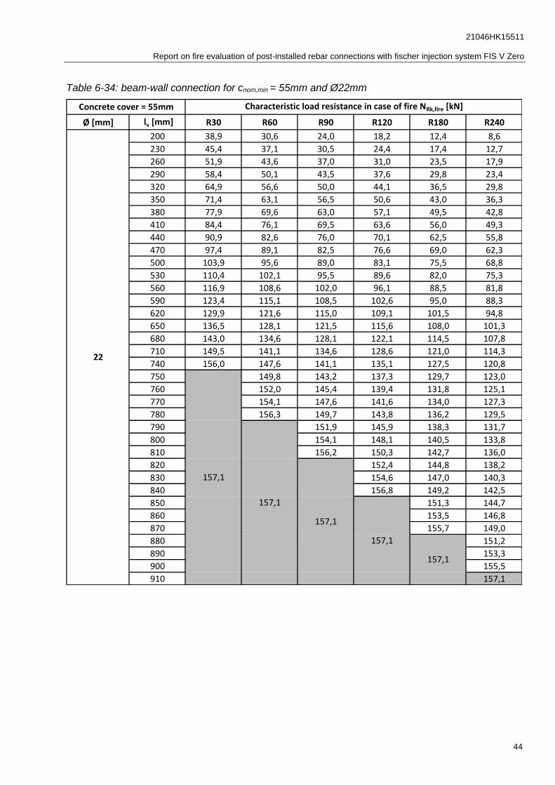
Table 6-34: beam-wall connection for cnom,min = 55mm and Ø22mm
Ø [mm] lv [mm] R30 R60 R90 R120 R180 R240
200 38,9 30,6 24,0 18,2 12,4 8,6
230 45,4 37,1 30,5 24,4 17,4 12,7
260 51,9 43,6 37,0 31,0 23,5 17,9
290 58,4 50,1 43,5 37,6 29,8 23,4
320 64,9 56,6 50,0 44,1 36,5 29,8
350 71,4 63,1 56,5 50,6 43,0 36,3
380 77,9 69,6 63,0 57,1 49,5 42,8
410 84,4 76,1 69,5 63,6 56,0 49,3
440 90,9 82,6 76,0 70,1 62,5 55,8
470 97,4 89,1 82,5 76,6 69,0 62,3
500 103,9 95,6 89,0 83,1 75,5 68,8
530 110,4 102,1 95,5 89,6 82,0 75,3
560 116,9 108,6 102,0 96,1 88,5 81,8
590 123,4 115,1 108,5 102,6 95,0 88,3
620 129,9 121,6 115,0 109,1 101,5 94,8
650 136,5 128,1 121,5 115,6 108,0 101,3
680 143,0 134,6 128,1 122,1 114,5 107,8
710 149,5 141,1 134,6 128,6 121,0 114,3
740 156,0 147,6 141,1 135,1 127,5 120,8
750 149,8 143,2 137,3 129,7 123,0
760 152,0 145,4 139,4 131,8 125,1
770 154,1 147,6 141,6 134,0 127,3
780 156,3 149,7 143,8 136,2 129,5
790 151,9 145,9 138,3 131,7
800 154,1 148,1 140,5 133,8
810 156,2 150,3 142,7 136,0
820 152,4 144,8 138,2
830 154,6 147,0 140,3
840 156,8 149,2 142,5
850 151,3 144,7
860 153,5 146,8
870 155,7 149,0
880 151,2
890 153,3
900 155,5
910 157,1
157,1
Concrete cover = 55mm Characteristic load resistance in case of fire NRk,fire [kN]
22
157,1
157,1
157,1
157,1

21046HK15511
Report on fire evaluation of post-installed rebar connections with fischer injection system FIS V Zero
45
Table 6-35: beam-wall connection for cnom,min = 55mm and Ø24mm
Ø [mm] lv [mm] R30 R60 R90 R120 R180 R240
200 38,9 30,6 24,0 18,2 12,4 8,6
230 45,4 37,1 30,5 24,4 17,4 12,7
260 51,9 43,6 37,0 31,0 23,5 17,9
290 58,4 50,1 43,5 37,6 29,8 23,4
320 64,9 56,6 50,0 44,1 36,5 29,8
350 71,4 63,1 56,5 50,6 43,0 36,3
380 77,9 69,6 63,0 57,1 49,5 42,8
410 84,4 76,1 69,5 63,6 56,0 49,3
440 90,9 82,6 76,0 70,1 62,5 55,8
470 97,4 89,1 82,5 76,6 69,0 62,3
500 103,9 95,6 89,0 83,1 75,5 68,8
530 110,4 102,1 95,5 89,6 82,0 75,3
560 116,9 108,6 102,0 96,1 88,5 81,8
590 123,4 115,1 108,5 102,6 95,0 88,3
620 129,9 121,6 115,0 109,1 101,5 94,8
650 136,5 128,1 121,5 115,6 108,0 101,3
680 143,0 134,6 128,1 122,1 114,5 107,8
710 149,5 141,1 134,6 128,6 121,0 114,3
740 156,0 147,6 141,1 135,1 127,5 120,8
750 149,8 143,2 137,3 129,7 123,0
760 152,0 145,4 139,4 131,8 125,1
770 154,1 147,6 141,6 134,0 127,3
780 156,3 149,7 143,8 136,2 129,5
790 151,9 145,9 138,3 131,7
800 154,1 148,1 140,5 133,8
810 156,2 150,3 142,7 136,0
820 152,4 144,8 138,2
830 154,6 147,0 140,3
840 156,8 149,2 142,5
850 151,3 144,7
860 153,5 146,8
870 155,7 149,0
880 151,2
890 153,3
900 155,5
910 157,1
157,1
Concrete cover = 55mm Characteristic load resistance in case of fire NRk,fire [kN]
24
157,1
157,1
157,1
157,1

21046HK15511
Report on fire evaluation of post-installed rebar connections with fischer injection system FIS V Zero
46
Table 6-36: beam-wall connection for cnom,min = 55mm and Ø25mm
Ø [mm] lv [mm] R30 R60 R90 R120 R180 R240
250 62,8 52,0 43,5 35,6 25,6 19,0
280 71,0 60,1 51,6 43,8 33,4 25,8
310 79,1 68,2 59,8 52,0 41,4 32,9
340 87,2 76,4 67,9 60,1 49,6 40,9
370 95,3 84,5 76,0 68,2 57,7 49,1
400 103,5 92,6 84,2 76,3 65,9 57,2
430 111,6 100,7 92,3 84,5 74,0 65,3
460 119,7 108,9 100,4 92,6 82,1 73,5
490 127,9 117,0 108,5 100,7 90,3 81,6
520 136,0 125,1 116,7 108,9 98,4 89,7
550 144,1 133,3 124,8 117,0 106,5 97,8
580 152,2 141,4 132,9 125,1 114,6 106,0
610 160,4 149,5 141,1 133,2 122,8 114,1
640 168,5 157,6 149,2 141,4 130,9 122,2
670 176,6 165,8 157,3 149,5 139,0 130,4
700 184,8 173,9 165,4 157,6 147,2 138,5
730 192,9 182,0 173,6 165,8 155,3 146,6
760 201,0 190,2 181,7 173,9 163,4 154,7
790 209,1 198,3 189,8 182,0 171,6 162,9
820 217,3 206,4 198,0 190,1 179,7 171,0
850 225,4 214,5 206,1 198,3 187,8 179,1
880 233,5 222,7 214,2 206,4 195,9 187,3
910 241,7 230,8 222,4 214,5 204,1 195,4
920 244,4 233,5 225,1 217,2 206,8 198,1
930 236,2 227,8 219,9 209,5 200,8
940 238,9 230,5 222,7 212,2 203,5
950 241,6 233,2 225,4 214,9 206,2
960 244,4 235,9 228,1 217,6 208,9
970 238,6 230,8 220,3 211,6
980 241,3 233,5 223,0 214,4
990 244,0 236,2 225,7 217,1
1000 238,9 228,5 219,8
1010 241,6 231,2 222,5
1020 244,3 233,9 225,2
1030 236,6 227,9
1040 239,3 230,6
1050 242,0 233,3
1060 244,7 236,0
1070 238,7
1080 241,5
1090 244,2
1100 245,4
245,4
245,4
25
Concrete cover = 55mm Characteristic load resistance in case of fire NRk,fire [kN]
245,4
245,4
245,4
21046HK15511
Report on fire evaluation of post-installed rebar connections with fischer injection system FIS V Zero
47
7. References
[1] Project 21029HK15511_1: Report on fire tests for post-installed rebars according to
EAD 330087-00-0601 with the fischer injection system FIS V Zero in mixing ratio 5:1 February
2021.
[2] DIN EN 1992-1-2, 2010-12: Eurocode 2: Design of concrete structures - Part 1-2: General rules
- Structural fire design; German version EN 1992-1-2:2004 + AC:2008.
[3] DIN EN 1993-1-2, 2010-12: Eurocode 3: Design of steel structures - Part 1-2: General rules -
Structural fire design; German version EN 1993-1-2:2005 + AC:2009.
[4] DIN EN 1363-1, 2012-10: Fire resistance tests - Part 1: General Requirements.
[5] DIN EN 1992-1-1, 2011-01: Eurocode 2: Design of concrete structures - Part 1-1: General rules
and rules for buildings.
[6]
[7]
[8]
ISO 834-1:1999: Fire resistance tests - Elements of building construction - Part 1: General
requirements.
Project 21029HK15511_3: Assessment of heating sleeve tests with fischer injection system
FIS V Zero in mixing ratio 5:1 according to EAD 330087-00-0601 April 2021.
EOTA: EAD 330087-00-0601 - Systems for post-installed Rebar Connections with Mortar (Version May 2018).
[9] Europäisch Technische Bewertung ETA-20/0574 Mai 2021