Embed Size (px)
Citation preview
Report for TUCSS THE HULME 2012 Competition by Er. Kee Ching Guan
1
REPORT ON THE EFFECTS OF THE
BASE GROUTING / DCM ON
DEEP FOUNDATION BORED PILES
AT
MARINA BAY
BUSINESS FINANCIAL CENTRE
A Report Presented to the TUCSS for the
THE HULME PRIZE 2012 COMPETITION
31 July 2012
Report Submitted by: - - - - - - - - - - - - - - - - - - - - Er. KEE CHING GUAN IC: S7975339D P.Eng. (S'pore), Grad.Eng. (M'sia), MIES, MSSSS-StEr, Grad.IEM, B.Eng. (Hons, NTU, S'pore), M.Sc. (Geot. Eng., NTU, S'pore)
Report for TUCSS THE HULME 2012 Competition by Er. Kee Ching Guan
2
ABSTRACT
The author would like to submit his report on one of the project involved in his
engineering life. The project is at Marina Bay Business Financial Centre. The
author would describe his involvement in this project. The focus of this report
would describe the author’s analysis on the instrumented test piles results for the
deep foundation bored piles. The effects of base grouting and Deep Cement Mixing
(DCM) on the pile performance would be described. Encouraging results are
presented and the outcome of the analysis could help in the improvement of the
deep foundation Bored Pile design in Singapore.
Report for TUCSS THE HULME 2012 Competition by Er. Kee Ching Guan
3
ABSTRACT 2
CONTENT 3
EFFECT S OF BASE GROUTING ON PILES AT
MARINA BAY BUSINESS AND FINANCIAL CENTRE 4
Introduction of Project 4
Problem Analysis 5
Design and Development of Solutions 11
Back analysis and interpretation of the ultimate load tests rests 16
- Effects of base grouting 16
- Effects of improved soil layer 21
- Effects of construction method 23
Quality control & quality assurance for construction of bored piles 25
- Verification of pile performance of working piles 28
Evaluation of Outcomes and Impacts 33
Responsibility for Decisions 34
Managing Engineering Activities 34
Exercising Sound Judgement 41
Communication 41
CONCLUSION 42
Report for TUCSS THE HULME 2012 Competition by Er. Kee Ching Guan
4
EFFECT S OF BASE GROUTING ON PILES AT
MARINA BAY BUSINESS AND FINANCIAL CENTRE
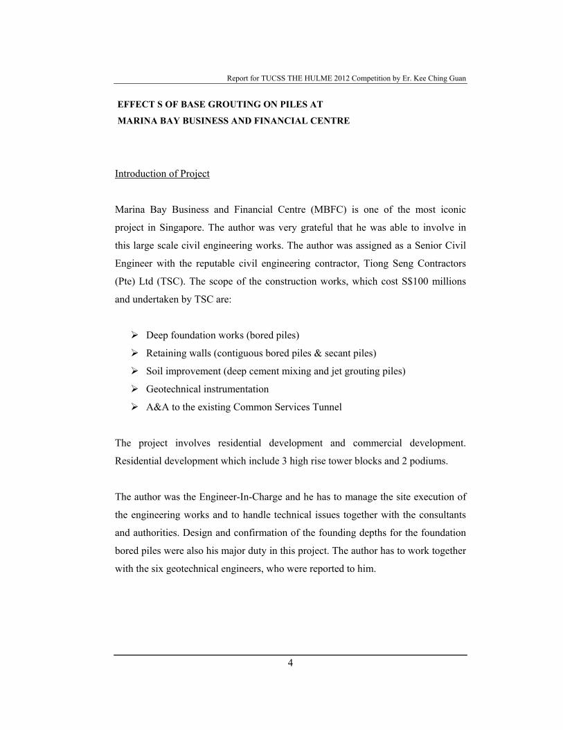
Introduction of Project
Marina Bay Business and Financial Centre (MBFC) is one of the most iconic
project in Singapore. The author was very grateful that he was able to involve in
this large scale civil engineering works. The author was assigned as a Senior Civil
Engineer with the reputable civil engineering contractor, Tiong Seng Contractors
(Pte) Ltd (TSC). The scope of the construction works, which cost S$100 millions
and undertaken by TSC are:
Deep foundation works (bored piles)
Retaining walls (contiguous bored piles & secant piles)
Soil improvement (deep cement mixing and jet grouting piles)
Geotechnical instrumentation
A&A to the existing Common Services Tunnel
The project involves residential development and commercial development.
Residential development which include 3 high rise tower blocks and 2 podiums.
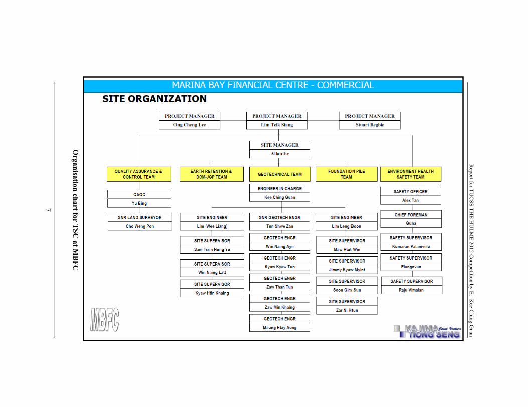
The author was the Engineer-In-Charge and he has to manage the site execution of
the engineering works and to handle technical issues together with the consultants
and authorities. Design and confirmation of the founding depths for the foundation
bored piles were also his major duty in this project. The author has to work together
with the six geotechnical engineers, who were reported to him.
Report for TUCSS THE HULME 2012 Competition by Er. Kee Ching Guan
5
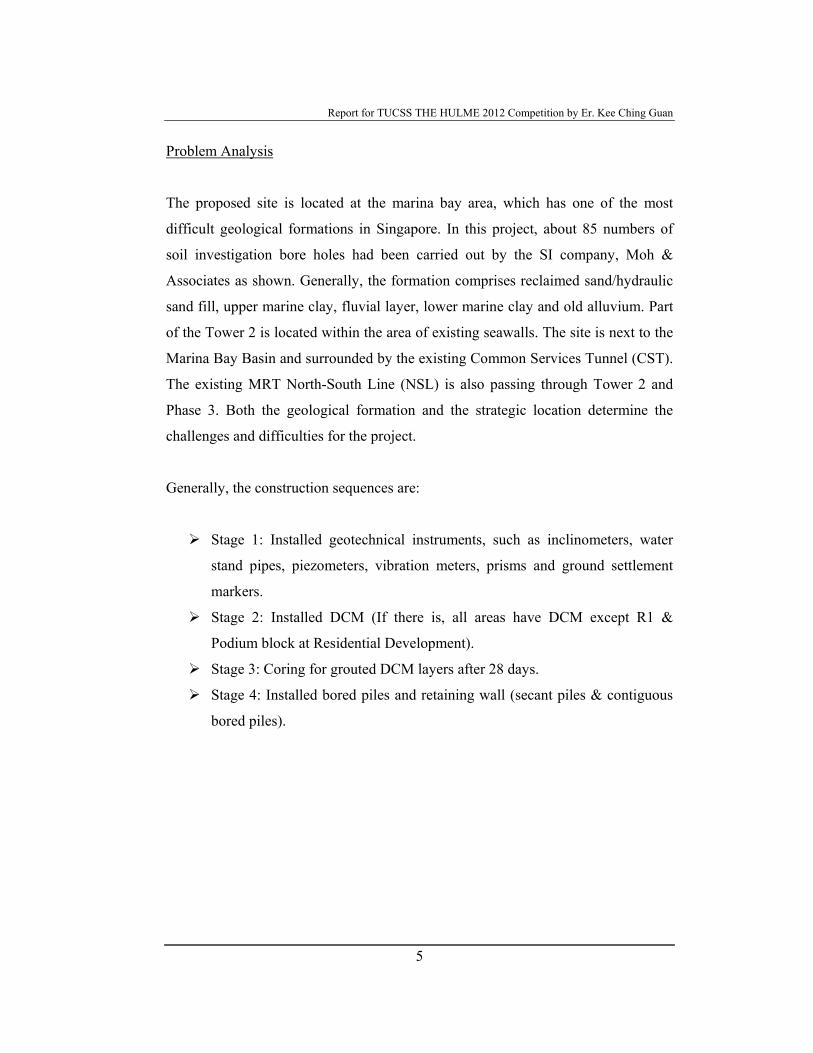
Problem Analysis
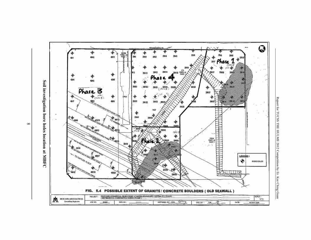
The proposed site is located at the marina bay area, which has one of the most
difficult geological formations in Singapore. In this project, about 85 numbers of
soil investigation bore holes had been carried out by the SI company, Moh &
Associates as shown. Generally, the formation comprises reclaimed sand/hydraulic
sand fill, upper marine clay, fluvial layer, lower marine clay and old alluvium. Part
of the Tower 2 is located within the area of existing seawalls. The site is next to the
Marina Bay Basin and surrounded by the existing Common Services Tunnel (CST).
The existing MRT North-South Line (NSL) is also passing through Tower 2 and
Phase 3. Both the geological formation and the strategic location determine the
challenges and difficulties for the project.
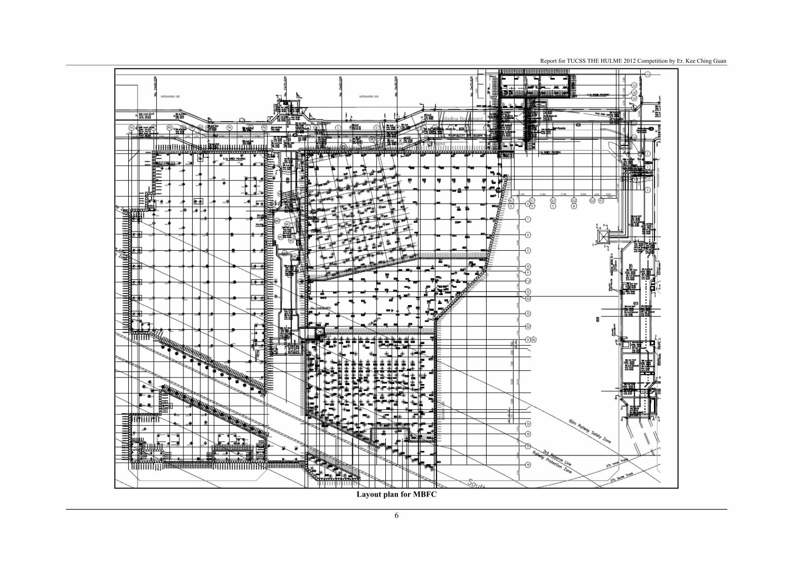
Generally, the construction sequences are:
Stage 1: Installed geotechnical instruments, such as inclinometers, water
stand pipes, piezometers, vibration meters, prisms and ground settlement
markers.
Stage 2: Installed DCM (If there is, all areas have DCM except R1 &
Podium block at Residential Development).
Stage 3: Coring for grouted DCM layers after 28 days.
Stage 4: Installed bored piles and retaining wall (secant piles & contiguous
bored piles).
Report for TUCSS THE HULME 2012 Competition by Er. Kee Ching Guan
6
Layout plan for MBFC
Report for TU
CSS TH
E HU
LME 2012 C
ompetition by Er. K
ee Ching G
uan
7
Organisation chart for T
SC at M
BFC
Report for TU
CSS TH
E HU
LME 2012 C
ompetition by Er. K
ee Ching G
uan
8
Soil investigation bore holes location at MB
FC
Report for TUCSS THE HULME 2012 Competition by Er. Kee Ching Guan
9
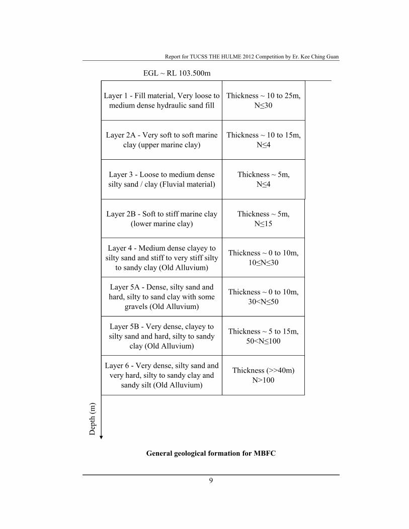
General geological formation for MBFC
Thickness ~ 10 to 25m, N≤30
EGL ~ RL 103.500m
Layer 1 - Fill material, Very loose to medium dense hydraulic sand fill
Layer 2A - Very soft to soft marine clay (upper marine clay)
Thickness ~ 10 to 15m, N≤4
Layer 3 - Loose to medium dense silty sand / clay (Fluvial material)
Thickness ~ 5m, N≤4
Layer 2B - Soft to stiff marine clay (lower marine clay)
Thickness ~ 5m, N≤15
Layer 4 - Medium dense clayey to silty sand and stiff to very stiff silty
to sandy clay (Old Alluvium)
Thickness ~ 0 to 10m, 10≤N≤30
Layer 5A - Dense, silty sand and hard, silty to sand clay with some
gravels (Old Alluvium)
Thickness ~ 0 to 10m, 30<N≤50
Layer 5B - Very dense, clayey to silty sand and hard, silty to sandy
clay (Old Alluvium)
Thickness ~ 5 to 15m, 50<N≤100
Layer 6 - Very dense, silty sand and very hard, silty to sandy clay and
sandy silt (Old Alluvium)
Thickness (>>40m)N>100
Dep
th (m
)
Report for TUCSS THE HULME 2012 Competition by Er. Kee Ching Guan
10
In this report, bored piles were only discussed. Bored piles were the first
engineering works commenced in this project at Residential Development since
there was no basement and no soil improvement was required in this area. In this
project, the geotechnical design for the bored piles is the responsibility of TSC. This
was clearly stated in the contract specifications as “The contractor shall be solely
responsible for the geotechnical design and installation of working piles which
shall support the specified loads with appropriate factor of safety”. Therefore, it
was important to come out the design calculations with the reasonable and
agreeable parameters.
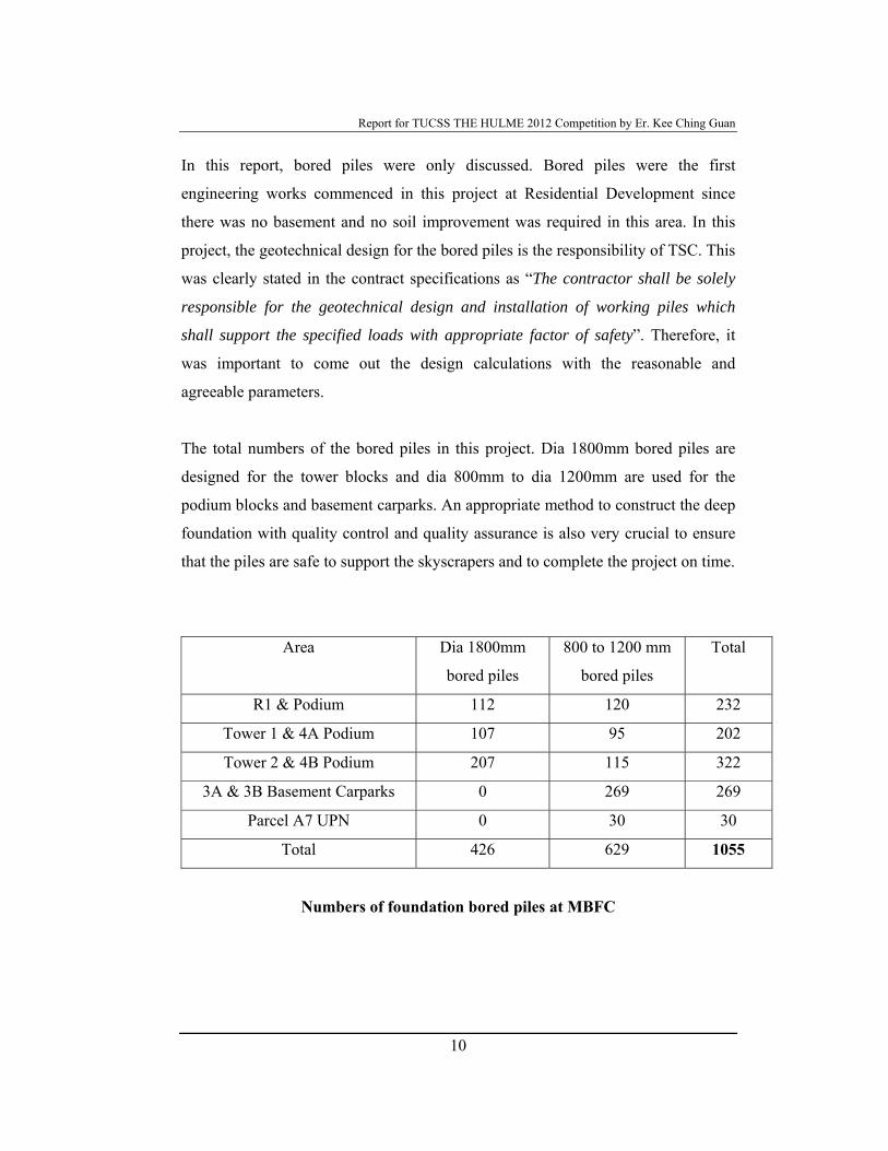
The total numbers of the bored piles in this project. Dia 1800mm bored piles are
designed for the tower blocks and dia 800mm to dia 1200mm are used for the
podium blocks and basement carparks. An appropriate method to construct the deep
foundation with quality control and quality assurance is also very crucial to ensure
that the piles are safe to support the skyscrapers and to complete the project on time.
Area Dia 1800mm
bored piles
800 to 1200 mm
bored piles
Total
R1 & Podium 112 120 232
Tower 1 & 4A Podium 107 95 202
Tower 2 & 4B Podium 207 115 322
3A & 3B Basement Carparks 0 269 269
Parcel A7 UPN 0 30 30
Total 426 629 1055
Numbers of foundation bored piles at MBFC
Report for TUCSS THE HULME 2012 Competition by Er. Kee Ching Guan
11
Design and Development of Solutions
In order to handle such large extent of the bored piling works at MBFC, a
systematic approach in the design and construction was required to be established
prior commencement of works.
Firstly, design equations and assumed design parameters have been discussed and
agreed with the C&S Consultant, Meinhardt (Singapore) Pte Ltd (MSPL), and
specialist contractors, Resource Piling Pte Ltd (RPPL) and KH Foges Pte Ltd (KH).
In this project, the author was very grateful to work with the following professional
personnel.
MSPL: Er. Kam Mun Wai, Dr. Junied Qureshi (Qualified Person’s
representatives)
TSC: Prof. Harry Tan (TSC’s specialist consultant), Er. Lim Kim Chai & Er.
Dr. Indra ( TSC’s consultants)
RPPL: Er. Foo Hee Kang (Professional Engineer from the specialist
contractor)
KH: Er. Dr. IH Wong (KH’s specialist consultant)
The geotechnical design for the bored pile is:
Case 1: 0.20.2
, ssultsp
AfQQ =≥
Case 2: 5.25.2
,, ppssultpultsp
AfAfQQQ
+=
+≥
Case 3: )5.1
()5.1
( ,,,,
,,
psfsnsfspsfspsfs
nsfspsfs
p AfAf
Q ηη −=−≥
Where Qp = working capacity the pile;
Qs,ult = ultimate skin resistance (kN)
Report for TUCSS THE HULME 2012 Competition by Er. Kee Ching Guan
12
fs = ultimate skin friction (kN/m2)
As = Circumference area (m2)
Qp,ult = ultimate base resistance (kN)
fp = ultimate end bearing (kN/m2)
Qs, psf = positive skin resistance below the neutral point (kN)
Qs,nsf = downdrag forces or negative skin friction (kN)
η = mobilisation factor for downdrag forces
The bored piles depth has to be designed to satisfy all the three cases. The assumed
design parameters are shown below:
Ultimate skin friction, fs = 2N for soil with SPT N <100 and fs = 300kN/m2
for soil with SPT N>100;
Ultimate end bearing, fp = 7000kN/m2;
Negative skin friction, fs,nsf = β x σv', where β = 0.35 for sand and β = 0.22
for marine clay.
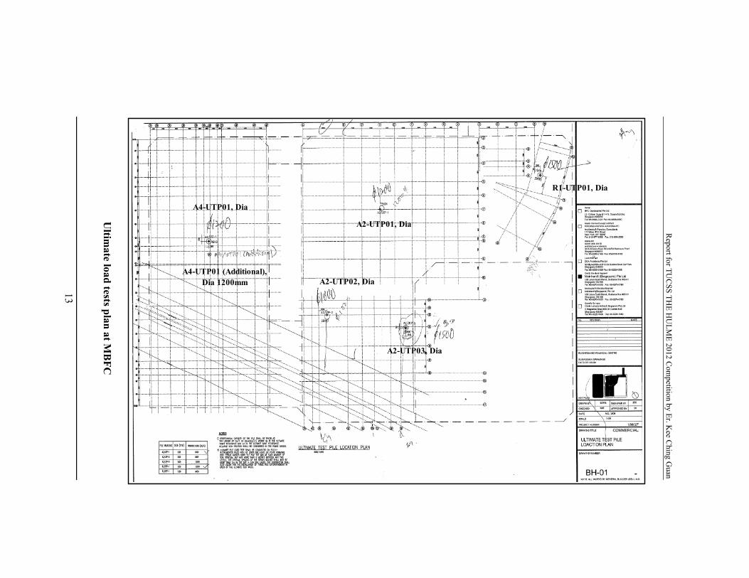
In order to verify and confirm the design parameters are reasonably correct and
reliable. Six numbers of instrumented ultimate load tests had been conducted in
MBFC, i.e. 2 numbers for dia 1500mm piles, 1 number for dia 1000mm pile and 3
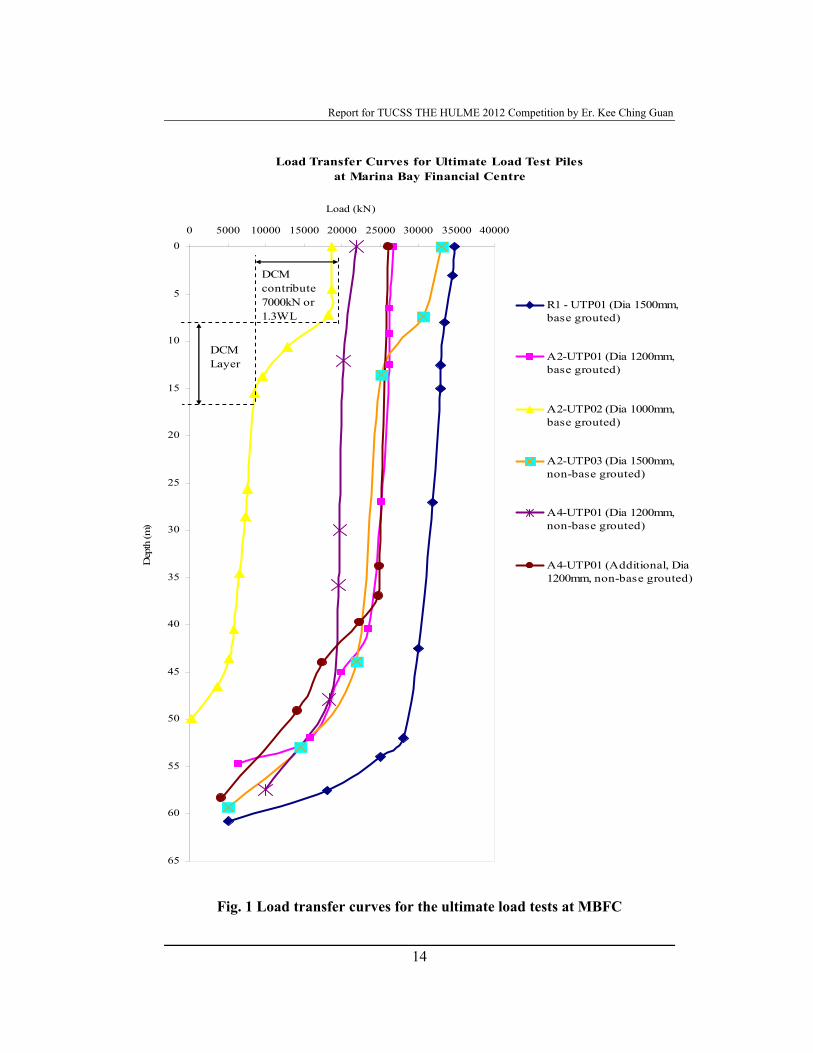
numbers for dia 1200mm piles. The load transfer curves for all the six ultimate load
tests are shown. The summaries of results of the instrumented pile loading tests are
tabulated.
Report for TU
CSS TH
E HU
LME 2012 C
ompetition by Er. K
ee Ching G
uan
13
Ultim
ate load tests plan at MB
FC
A4-UTP01, Dia
A4-UTP01 (Additional), Dia 1200mm
A2-UTP01, Dia
A2-UTP03, Dia
A2-UTP02, Dia
R1-UTP01, Dia
Report for TUCSS THE HULME 2012 Competition by Er. Kee Ching Guan
14
Fig. 1 Load transfer curves for the ultimate load tests at MBFC
Load Transfer Curves for Ultimate Load Test Piles at Marina Bay Financial Centre
0
5
10
15
20
25
30
35
40
45
50
55
60
65
0 5000 10000 15000 20000 25000 30000 35000 40000
Load (kN)
Dep
th (m
)
R1 - UTP01 (Dia 1500mm,base grouted)
A2-UTP01 (Dia 1200mm,base grouted)
A2-UTP02 (Dia 1000mm,base grouted)
A2-UTP03 (Dia 1500mm,non-base grouted)
A4-UTP01 (Dia 1200mm,non-base grouted)
A4-UTP01 (Additional, Dia1200mm, non-base grouted)
DCM Layer
DCM contribute 7000kN or 1.3WL
Report for TUCSS THE HULME 2012 Competition by Er. Kee Ching Guan
15
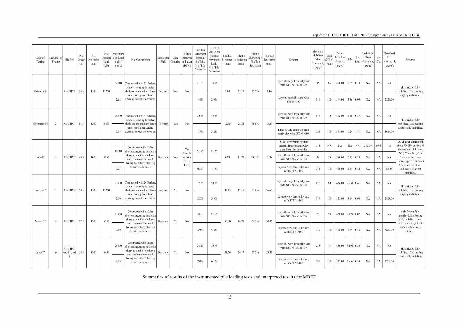
Summaries of results of the instrumented pile loading tests and interpreted results for MBFC
Date of Testing
Sequence of Testing Pile Ref.
Pile Length
(m)
Pile Dimension
(mm)
Pile Working
Load (kN)
Maximum Test Load
( kN / x WL)
Pile Construction Stabilising Fluid
Base Grouting
Within improved soil layer (DCM)
Pile Top Settlement
(mm) at 2 x WL , % of Pile
Dimension
Pile Top Settlement
(mm) at maximum
load , % of Pile
Dimension
Residual Settlement
(mm)
Elastic Shortening
(mm)
Elastic Shortening /
Pile Top Settlement
Pile Toe Settlement
(mm)Stratum
Maximum Mobilised
Skin Friction, fs
(kN/m2)
Mean SPT N-Value
Mean Effective Stress, σv' (kN/m2)
fs/Nβ =
fs/σv'
Undrained Shear
Strength, cu
(kN/m2)
α = fs/cu
Mobilised End
Bearing, fp
(kN/m2)
Remarks
34780 21.63 30.63 Layer 5B, very dense silty sand with SPT N ~ 50 to 100 45 65 470.00 0.69 0.10 NA NA NA
2.62 1.4% 2.0% Layer 6, hard silty sand with SPT N >100 556 100 564.00 5.56 0.99 NA NA 2829.00
26710 20.75 38.63 Layer 5B, very dense silty sand with SPT N ~ 50 to 100 175 70 478.00 2.50 0.37 NA NA NA
3.16 1.7% 3.2% Layer 6, very dense and hard sandy clay with SPT N >100 924 100 541.00 9.24 1.71 NA NA 5684.00
DCM Layer within existing sand fill layer (Marine Clay
start from 16m onwards)375 NA NA NA NA 350.00 0.93 NA
Layer 5B, very dense silty sand with SPT N ~ 50 to 100 38 50 380.00 0.75 0.10 NA NA NA
3.25 0.5% 1.1% Layer 6, very dense silty sand with SPT N >100 214 100 450.00 2.14 0.48 NA NA 335.00
33130 32.25 53.75 Layer 5B, very dense silty sand with SPT N ~ 50 to 100 176 60 434.00 2.933 0.41 NA NA NA
2.50 2.2% 3.6% Layer 6, very dense silty sand with SPT N >100 314 100 525.00 3.14 0.60 NA NA 2829.00
21930 46.5 66.63 Layer 5B, very dense silty sand with SPT N ~ 50 to 100 30 70 430.00 0.429 0.07 NA NA NA
2.60 3.9% 5.6% Layer 6, very dense silty sand with SPT N >100 229 100 528.80 2.29 0.43 NA NA 8860.00
26150 24.25 73.75 Layer 5B, very dense silty sand with SPT N ~ 50 to 100 233 73 430.00 3.192 0.54 NA NA NA
3.09 2.0% 6.1% Layer 6, very dense silty sand with SPT N >100 286 100 537.00 2.856 0.53 NA NA 3713.00
18680
Yes
Yes
Polymer
Constructed with 23.5m long temporary casing to protect the loose and medium dense
sand, boring bucket and cleaning bucket under water.
0.00
13.29
7.46
65.6%
60.8R1-UTP01
A2-UTP01 54.7 8450
Constructed with 31.5m long temporary casing to protect the loose and medium dense
sand, boring bucket and cleaning bucket under water.
Polymer
1500
1200
13250 75.7%23.17
No 25.34
Constructed with 11.3m short casing, using bentonite slurry to stabilise the loose and medium dense sand,
boring bucket and cleaning bucket under water.
No 9.00
12.75
Polymer No
Yes (from 9m to 16m below EGL)
No
Bentonite Yes
No
A2-UTP02 49.9 1000 5750
A2-UTP03 59.3 1500 13250
Constructed with 26.8m long temporary casing to protect the loose and medium dense
sand, boring bucket and cleaning bucket under water.
8450
Constructed with 12.0m short casing, using bentonite slurry to stabilise the loose and medium dense sand,
boring bucket and cleaning bucket under water.
Bentonite No
100.0%11.250.88
35.25 17.15 31.9%
October-06
November-06
July-07
January-07
March-07
June-07A4-UTP01 (Additional
)58.3
A4-UTP01 57.5
36.60
1200 8450
Constructed with 15.0m short casing, using bentonite slurry to stabilise the loose and medium dense sand,
boring bucket and cleaning bucket under water.
Bentonite
50.00 16.21 24.3%
20.17
1200
No No 54.50
Skin friction fully mobilised. End bearing
slightly mobilised.
Skin friction fully mobilised. End bearing substantially mobilised.
DCM layer contributed about 7000kN or 40% of the test load (1.3 times WL). Therefore, skin friction at the lower
layers, Layer 5B & Layer 6 have not mobilised. End bearing has not
mobilised.
Skin friction fully mobilised. End bearing
slightly mobilised.
Skin fricion fully mobilised. End bering fully mobilised. Low
skin friction may due to bentonite filter cake
issue.
Skin friction fully mobilised. End bearing substantially mobilised.
50.42
5.375
27.3% 53.58
1
2
5
3
4
6
11.25
Report for TUCSS THE HULME 2012 Competition by Er. Kee Ching Guan
16
Back analysis and interpretation of the ultimate load tests results
The skin friction for the six load tests had been fully mobilised or substantially
mobilised at a relative displacement between the pile and soil of about 1.5% to 2%
pile diameter at maximum test loads, except for A2-UTP02. Generally, end bearing
for the test piles was not substantially / fully mobilised due to the fact that the piles
are rather long, from 49m to 60m. It was noted that substantial pile toe settlement of
about 0.5% to 4.5% pile diameter was required in order to slightly or substantially
mobilise the end bearing of the piles from about 2829kN/m2 to 8860kN/m2. It is
also to note that A4-UTP01 (Additional) was compensated and conducted at 6m
away from the A4-UTP01. This was because the pile performance for A4-UTP01
was not satisfactory and did not comply to the contract specifications.
The test results indicate a complex and erratic distribution of the relative pile soil
settlements, mobilised skin friction and mobilised end bearing. Various factors
would have contributed to the test results, such as base grouting, improved soil
layer (DCM) and construction method (different stabilising fluids). In the following
sections, factors affecting the test results would be discussed.
Effects of base grouting
Base grouting was required for all the foundation bored piles as specified in the
contract specifications. It involves installation of a grouting device (dia 32mm TAM
pipe) at the bottom of the steel cages or pile toe. Grouting hoses are attached to the
grouting device for preparation of three stages of post grouting after the pile has
been cast.
R1-UTP01, A2-UTP01 and A2-UTP02 had been base grouted at least 7days before
commencement of the load tests. Refer to Fig. 2, the pile toe settlement of R1-
UTP01 was 7.46mm or 0.49% pile diameter, when the end bearing had been
Report for TUCSS THE HULME 2012 Competition by Er. Kee Ching Guan
17
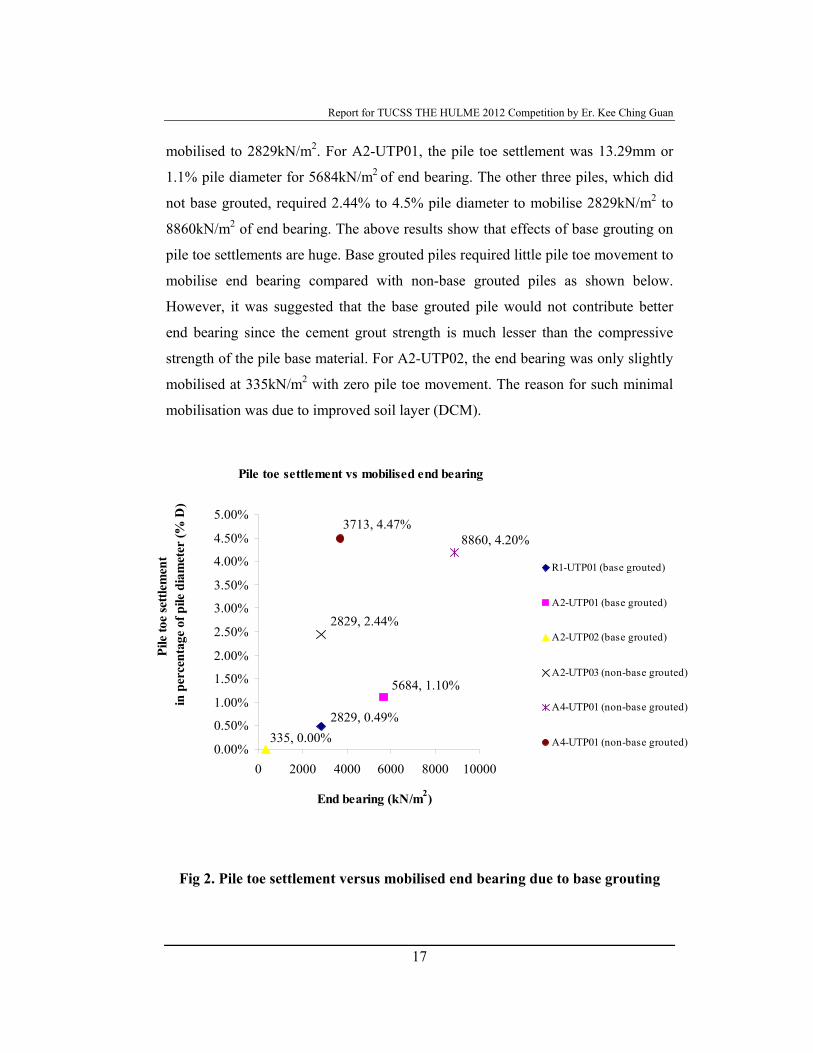
mobilised to 2829kN/m2. For A2-UTP01, the pile toe settlement was 13.29mm or
1.1% pile diameter for 5684kN/m2 of end bearing. The other three piles, which did
not base grouted, required 2.44% to 4.5% pile diameter to mobilise 2829kN/m2 to
8860kN/m2 of end bearing. The above results show that effects of base grouting on
pile toe settlements are huge. Base grouted piles required little pile toe movement to
mobilise end bearing compared with non-base grouted piles as shown below.
However, it was suggested that the base grouted pile would not contribute better
end bearing since the cement grout strength is much lesser than the compressive
strength of the pile base material. For A2-UTP02, the end bearing was only slightly
mobilised at 335kN/m2 with zero pile toe movement. The reason for such minimal
mobilisation was due to improved soil layer (DCM).
Fig 2. Pile toe settlement versus mobilised end bearing due to base grouting
Pile toe settlement vs mobilised end bearing
2829, 0.49%
5684, 1.10%
335, 0.00%
2829, 2.44%
8860, 4.20%3713, 4.47%
0.00%
0.50%
1.00%
1.50%
2.00%
2.50%
3.00%
3.50%
4.00%
4.50%
5.00%
0 2000 4000 6000 8000 10000
End bearing (kN/m2)
Pile
toe
settl
emen
t in
per
cent
age
of p
ile d
iam
eter
(% D
)
R1-UTP01 (base grouted)
A2-UTP01 (base grouted)
A2-UTP02 (base grouted)
A2-UTP03 (non-base grouted)
A4-UTP01 (non-base grouted)
A4-UTP01 (non-base grouted)
Report for TUCSS THE HULME 2012 Competition by Er. Kee Ching Guan
18
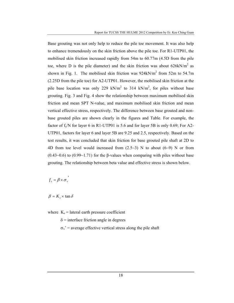
Base grouting was not only help to reduce the pile toe movement. It was also help
to enhance tremendously on the skin friction above the pile toe. For R1-UTP01, the
mobilised skin friction increased rapidly from 54m to 60.77m (4.5D from the pile
toe, where D is the pile diameter) and the skin friction was about 626kN/m2 as
shown in Fig. 1. The mobilised skin friction was 924kN/m2 from 52m to 54.7m
(2.25D from the pile toe) for A2-UTP01. However, the mobilised skin friction at the
pile base location was only 229 kN/m2 to 314 kN/m2, for piles without base
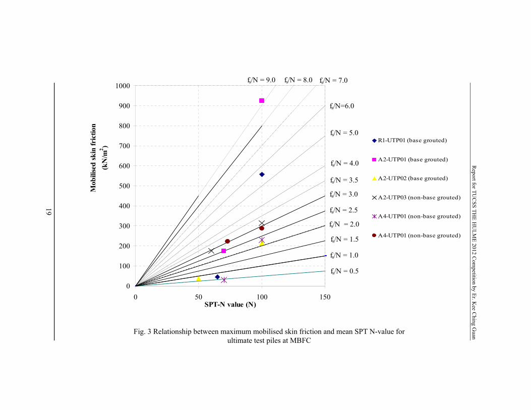
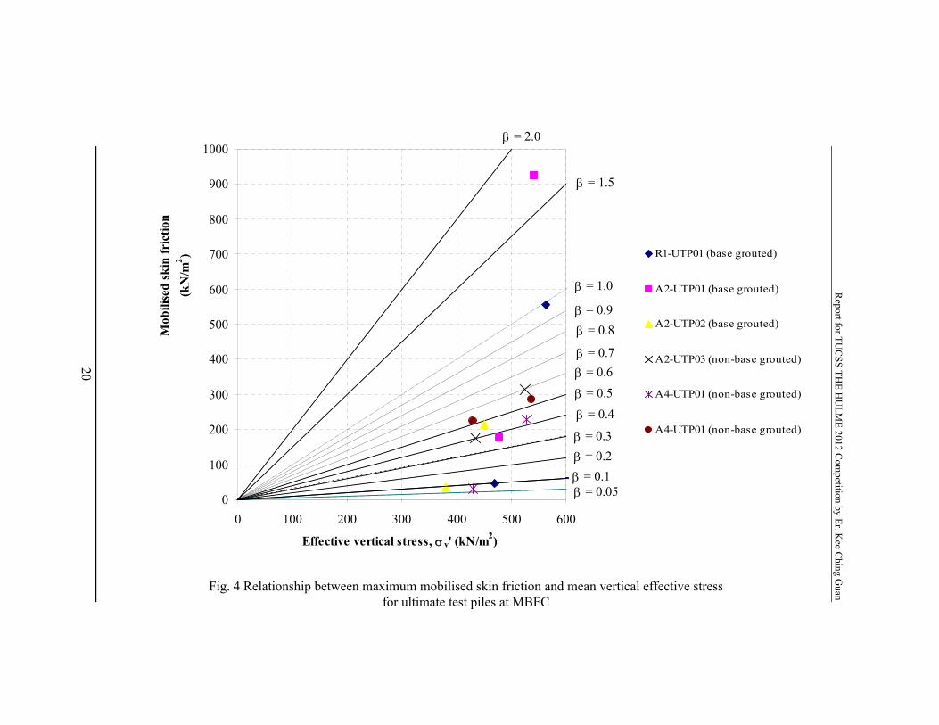
grouting. Fig. 3 and Fig. 4 show the relationship between maximum mobilised skin
friction and mean SPT N-value, and maximum mobilised skin friction and mean
vertical effective stress, respectively. The difference between base grouted and non-
base grouted piles are shown clearly in the figures and Table. For example, the
factor of fs/N for layer 6 in R1-UTP01 is 5.6 and for layer 5B is only 0.69; For A2-
UTP01, factors for layer 6 and layer 5B are 9.25 and 2.5, respectively. Based on the
test results, it was concluded that skin friction for base grouted pile shaft at 2D to
4D from toe level would increased from (2.5~3) N to about (6~9) N or from
(0.43~0.6) to (0.99~1.71) for the β-values when comparing with piles without base
grouting. The relationship between beta value and effective stress is shown below.
′×= vsf σβ
δβ tan×= sK
where Ks = lateral earth pressure coefficient
δ = interface friction angle in degrees
σv’ = average effective vertical stress along the pile shaft
Report for TU
CSS TH
E HU
LME 2012 C
ompetition by Er. K
ee Ching G
uan
19
Pile toe settlement vs mobilised end bearing
5684, 1.10%
2829, 2.44%
8860, 4.20%3713, 4.47%
2829, 0.49%335, 0.00%0.00%
0.50%
1.00%
1.50%
2.00%
2.50%
3.00%
3.50%
4.00%
4.50%
5.00%
0 2000 4000 6000 8000 10000
End bearing (kPa)
Pile
toe
settl
emen
t in
per
cent
age
of p
ile d
iam
eter
(% D
)R1-UTP01 (base grouted)
A2-UTP01 (base grouted)
A2-UTP02 (base grouted)
A2-UTP03 (non-base grouted)
A4-UTP01 (non-base grouted)
A4-UTP01 (non-base grouted)
fs/N = 0.5
fs/N = 1.0
fs/N = 1.5
fs/N = 2.0
fs/N = 2.5
fs/N = 3.0
fs/N = 3.5
fs/N = 4.0
fs/N = 5.0
fs/N = 7.0fs/N = 8.0fs/N = 9.0
fs/N=6.0
0
100
200
300
400
500
600
700
800
900
1000
0 50 100 150SPT-N value (N)
Mob
ilise
d sk
in fr
ictio
n (k
N/m
2 )
Fig. 3 Relationship between maximum mobilised skin friction and mean SPT N-value for ultimate test piles at MBFC
Report for TU
CSS TH
E HU
LME 2012 C
ompetition by Er. K
ee Ching G
uan
20
Pile toe settlement vs mobilised end bearing
5684, 1.10%
2829, 2.44%
8860, 4.20%3713, 4.47%
2829, 0.49%335, 0.00%0.00%
0.50%
1.00%
1.50%
2.00%
2.50%
3.00%
3.50%
4.00%
4.50%
5.00%
0 2000 4000 6000 8000 10000
End bearing (kPa)
Pile
toe
settl
emen
t in
per
cent
age
of p
ile d
iam
eter
(% D
)R1-UTP01 (base grouted)
A2-UTP01 (base grouted)
A2-UTP02 (base grouted)
A2-UTP03 (non-base grouted)
A4-UTP01 (non-base grouted)
A4-UTP01 (non-base grouted)
Fig.
β = 0.05 β = 0.1β = 0.2β = 0.3β = 0.4β = 0.5β = 0.6β = 0.7
β = 0.8
β = 1.0
β = 1.5
β = 2.0
β = 0.9
0
100
200
300
400
500
600
700
800
900
1000
0 100 200 300 400 500 600
Effective vertical stress, σv' (kN/m2)
Mob
ilise
d sk
in fr
ictio
n (k
N/m
2 )
Fig. 4 Relationship between maximum mobilised skin friction and mean vertical effective stress for ultimate test piles at MBFC
Report for TUCSS THE HULME 2012 Competition by Er. Kee Ching Guan
21
Effects of improved soil layer
The 5th ultimate load test pile, A2-UTP02, was installed on 9 June 2007 at 4B
Podium after the DCM had been completed at that area. The improved soil layer
was from RL 94.000m to RL 87.000m (7m thick) or about 9m to 16m from EGL.
The geological profile of the pile is as shown below:
Layer 1, 0 to 15.2m (EGL at RL 103.000m): Loose sand fill;
Layer 2A, 15.2 to 24.6m: Soft marine clay (upper);
Layer 3, 24.6 to 27.6m: Medium stiff silty clay;
Layer 2B, 27.6 to 31.4m: Soft marine clay (lower);
Layer 5A, 31.4 to 35.8m: Very stiff silty clay;
Layer 5B, 35.8 to 39.4m: Hard silty clay and dense silty sand;
Layer 6, 40 to 49.6m: Very dense silty sand.
For this pile, majority of the DCM layer was located within the loose sand layer.
The behaviour of the pile was totally different from the other five piles. The
mobilised skin friction for pile shaft at DCM layer was 375kN/m2, which is as good
as skin friction at soil with SPT N-value greater 100 (refer to Fig. 1 and the Table
above). The DCM layer had contributed about 7000kN skin resistance to the pile
load, which is about 1.3 times of the working load of the pile. Therefore, the skin
friction at the lower layers, such as Layer 5 and Layer 6, had not been substantially
mobilised. The mobilised pile bearing capacity was also minimal, at 355kN/m2.
With the combined effects of base grouting and improved soil layer, the pile toe
settlement is zero. As such, pile top settlement is same as the measured elastic
shortening.
It was noted that all the working piles would behave similar to A2-UTP02, since
DCM had to be completed prior installation of foundation bored piles. However, it
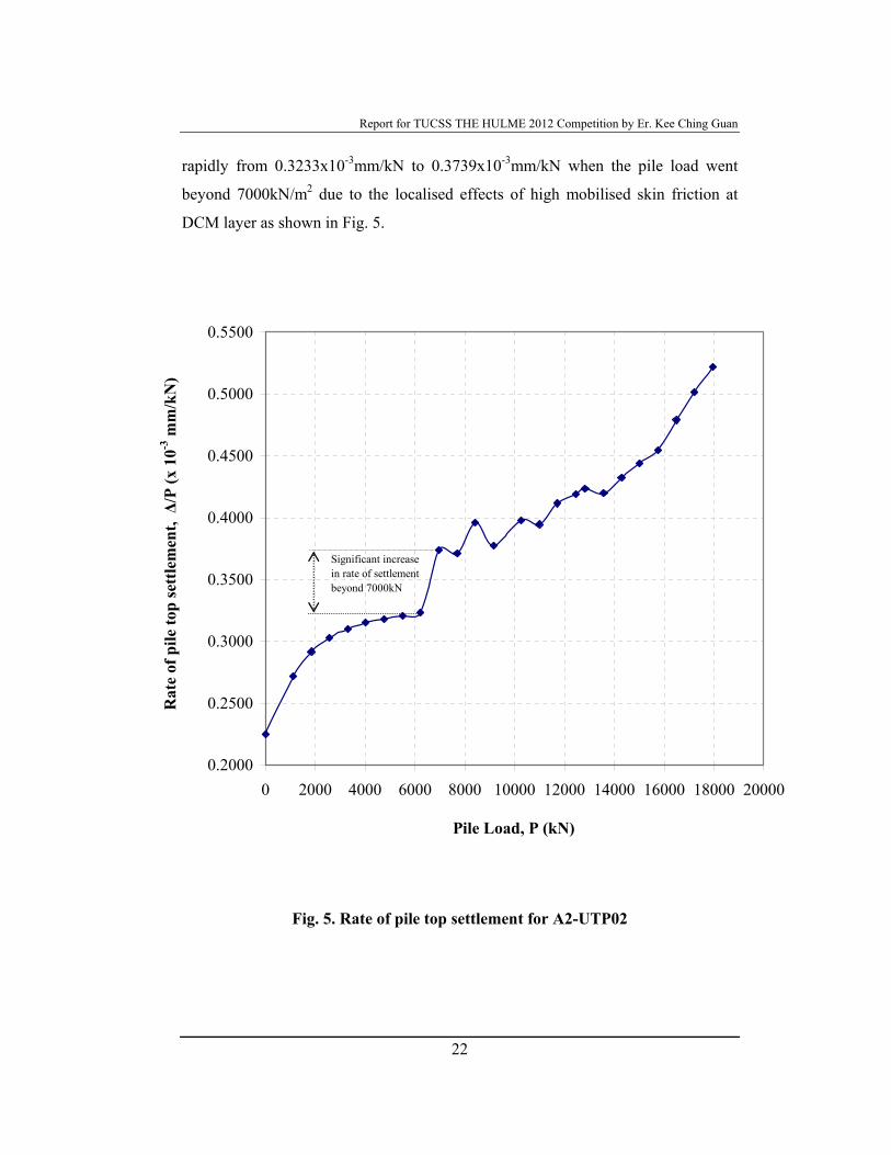
was also worthwhile to note that the rate of pile top settlement was increased
Report for TUCSS THE HULME 2012 Competition by Er. Kee Ching Guan
22
rapidly from 0.3233x10⁻³mm/kN to 0.3739x10⁻³mm/kN when the pile load went
beyond 7000kN/m2 due to the localised effects of high mobilised skin friction at
DCM layer as shown in Fig. 5.
Fig. 5. Rate of pile top settlement for A2-UTP02
0.2000
0.2500
0.3000
0.3500
0.4000
0.4500
0.5000
0.5500
0 2000 4000 6000 8000 10000 12000 14000 16000 18000 20000
Pile Load, P (kN)
Rat
e of
pile
top
sett
lem
ent,
Δ/P
(x 1
0-3 m
m/k
N)
Significant increase in rate of settlement beyond 7000kN
Report for TUCSS THE HULME 2012 Competition by Er. Kee Ching Guan
23
Effects of construction method
All the piles in MBFC were constructed under water instead of dry pile method due
to the geological formation of the site. The piles were deep, ranging from 50m to
80m and the construction time for one pile was long, boring and casting needed
ranging from about 18hours to 48hours.
Long temporary casings (20 to 30m depend on thickness of sand layer) were
required to protect the loose sand layer when polymer was used as stabilising fluid.
However, only short casing from 6 to 10m was required if bentonite was adopted to
stabilise the loose to medium dense sand layer, very soft to soft marine clay layer
and soft to medium stiff clay and sand layer. The reason that bentonite slurry can
stabilise and prevent the loose to medium dense layer (from toe of the temporary
casing up to the top of the very soft marine clay) from collapse during boring
operation is because the loose to medium dense sand layer is highly permeable.
Bentonite suspensions can seal the hole and provide the gel strength required to
move the solids out of the hole. In other words, it would form a filter cake on those
soil layers that are highly permeable to prevent loose to medium dense sand layer
from collapsing. Therefore, by adopting bentonite as stabilising fluid would have
the following advantages.
Short casing (6 to 10m) instead of long casing (20 to 30m) for polymer;
No joining and welding of casings are required for each individual piles;
Smaller machine / crane is needed;
No vibrator hammer or only smaller capacity of vibrator hammer (eg. 5tons
hammer) is needed for installation and extraction of casings;
Minimal vibration created (this is good for this site as MBFC is located at
LTA MRT railway reserves zone and URA CST 6m protection zone);
Report for TUCSS THE HULME 2012 Competition by Er. Kee Ching Guan
24
These were the main reasons that driven the ultimate load tests for A2-UTP02, A4-
UTP01 & A4-UTP01 (Additional) to be carried out using bentonite. All the 232
numbers of working piles at R1 & Podium were constructed using polymer and it
required lengthy construction time of four months from October 2006 to February
2007 to complete all the piles. The purpose of carrying out the three load tests using
bentonite was to prove to the Consultants that the piles performance would not be
compromised by adopting bentonite slurry. The successful of this approach would
ultimately shorten the construction period for the commercial development, i.e.
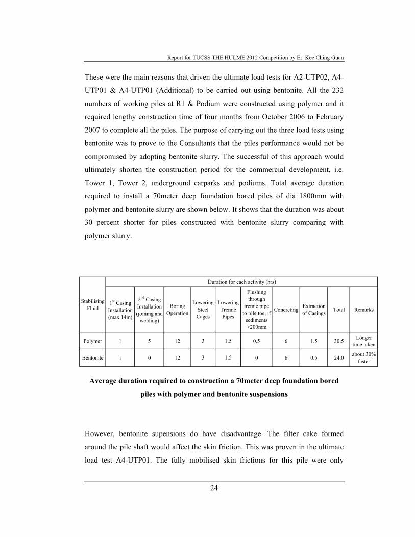
Tower 1, Tower 2, underground carparks and podiums. Total average duration
required to install a 70meter deep foundation bored piles of dia 1800mm with
polymer and bentonite slurry are shown below. It shows that the duration was about
30 percent shorter for piles constructed with bentonite slurry comparing with
polymer slurry.
Average duration required to construction a 70meter deep foundation bored
piles with polymer and bentonite suspensions
However, bentonite supensions do have disadvantage. The filter cake formed
around the pile shaft would affect the skin friction. This was proven in the ultimate
load test A4-UTP01. The fully mobilised skin frictions for this pile were only
Polymer 1 5 12 0.5 6 1.5 30.5 Longer time taken
Bentonite 1 0 12 0 6 0.5 24.0 about 30% faster
Total Remarks
Duration for each activity (hrs)
Lowering Steel Cages
Lowering Tremie Pipes
Extraction of Casings
1.5
1.5
3
3
Stabilising Fluid
1st Casing Installation (max 14m)
2nd Casing Installation (joining and
welding)
Boring Operation
Flushing through
tremie pipe to pile toe, if
sediments >200mm
Concreting
Report for TUCSS THE HULME 2012 Competition by Er. Kee Ching Guan
25
30kN/m2 for old alluvium (soil layers above layer 6) and 229kN/m2 for layer 6. It
was also need to note that the bore hole with bentonite suspensions was untouched
for at least 24hours when the boring was only few meters to reach the toe level.
This was due to boring rig faulty during the installation. It was concluded that the
thick filter cake was formed during the stoppage period and caused the lower
mobilised skin friction.
In order to verify this finding, another ultimate load test A4-UTP01 (Additional)
was installed and tested at 6m away from A4-UTP01. The pile was constructed in
continuous sequences without any disturbance. The mobilised skin friction for this
pile is much higher than the previous one. The mobilised skin frictions were
233kN/m2 and 286kN/m2 for layer 5 and layer 6, respectively.
Quality control & quality assurance for construction of bored piles
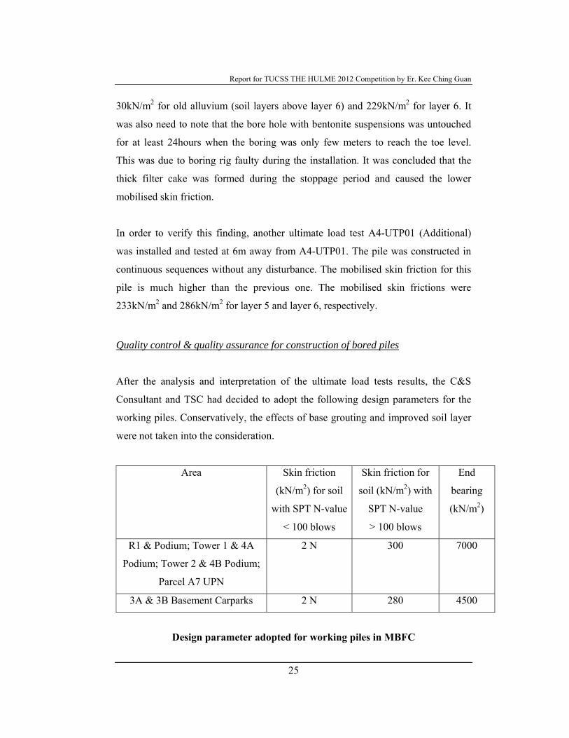
After the analysis and interpretation of the ultimate load tests results, the C&S
Consultant and TSC had decided to adopt the following design parameters for the
working piles. Conservatively, the effects of base grouting and improved soil layer
were not taken into the consideration.
Area Skin friction
(kN/m2) for soil
with SPT N-value
< 100 blows
Skin friction for
soil (kN/m2) with
SPT N-value
> 100 blows
End
bearing
(kN/m2)
R1 & Podium; Tower 1 & 4A
Podium; Tower 2 & 4B Podium;
Parcel A7 UPN
2 N 300 7000
3A & 3B Basement Carparks 2 N 280 4500
Design parameter adopted for working piles in MBFC
Report for TUCSS THE HULME 2012 Competition by Er. Kee Ching Guan
26
The quality control and quality assurance for the foundation bored piles must be in
placed in order to achieve the design. It was required to closely monitor the
progress of the foundation works due to the tight construction schedule.
Several forms had been created and implemented for the site supervisors and
geotechnical engineers to follow. The objective was to ensure that all the required
information was recorded, such as:
Setting out of the pile
Casing verticality
Time taken for each individual activities, such as casing installation, boring,
lower steel cages, tremie pipes and concreting
Quality of the bentonite / polymer suspensions (Strictly follow BS EN
1536:2000, Clause 6.5.2)
Bored out soil classifications
Ground level, casing level, pile penetration length, pay length and
reinforcement details
Concreting record to verify the wet concrete raising
Report for TUCSS THE HULME 2012 Competition by Er. Kee Ching Guan
27
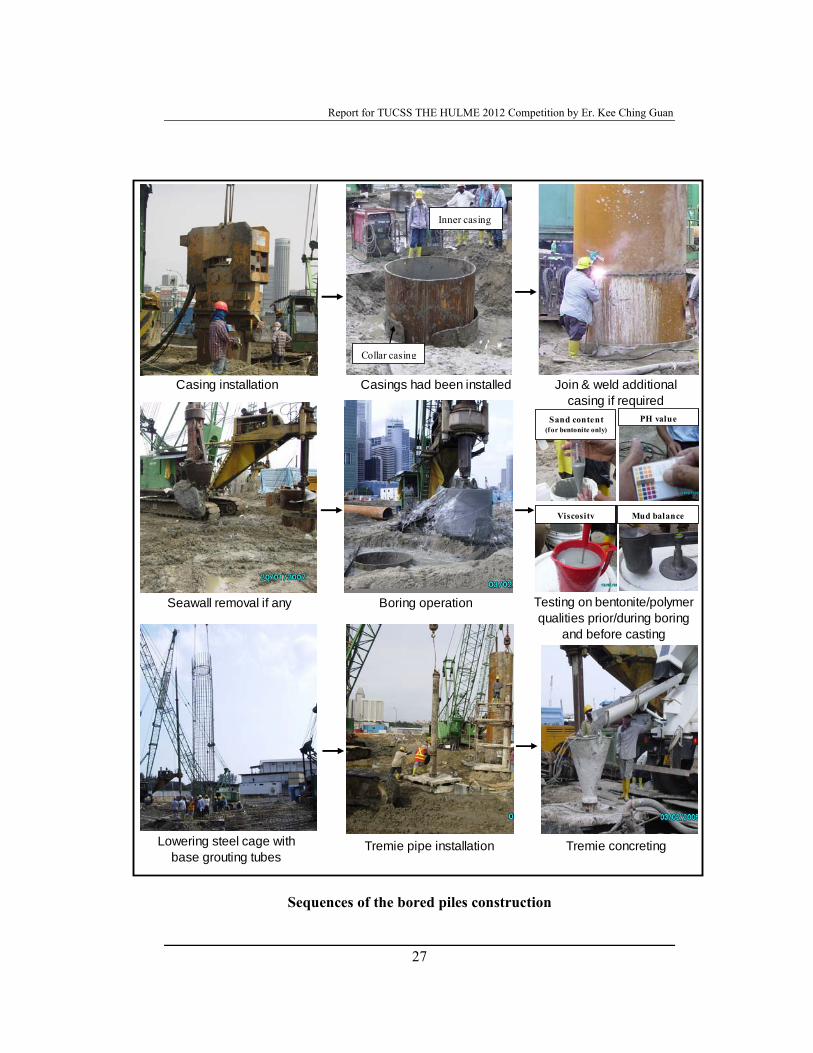
Sequences of the bored piles construction
Casing installation
Collar casing
Inner casing
Casings had been installed Join & weld additional casing if required
Seawall removal if any Boring operation
Lowering steel cage with base grouting tubes
Tremie pipe installation Tremie concreting
Testing on bentonite/polymer qualities prior/during boring
and before casting
Sand content (for bentonite only)
PH value
Viscosity Mud balance
Report for TUCSS THE HULME 2012 Competition by Er. Kee Ching Guan
28
Verification of pile performance of working piles
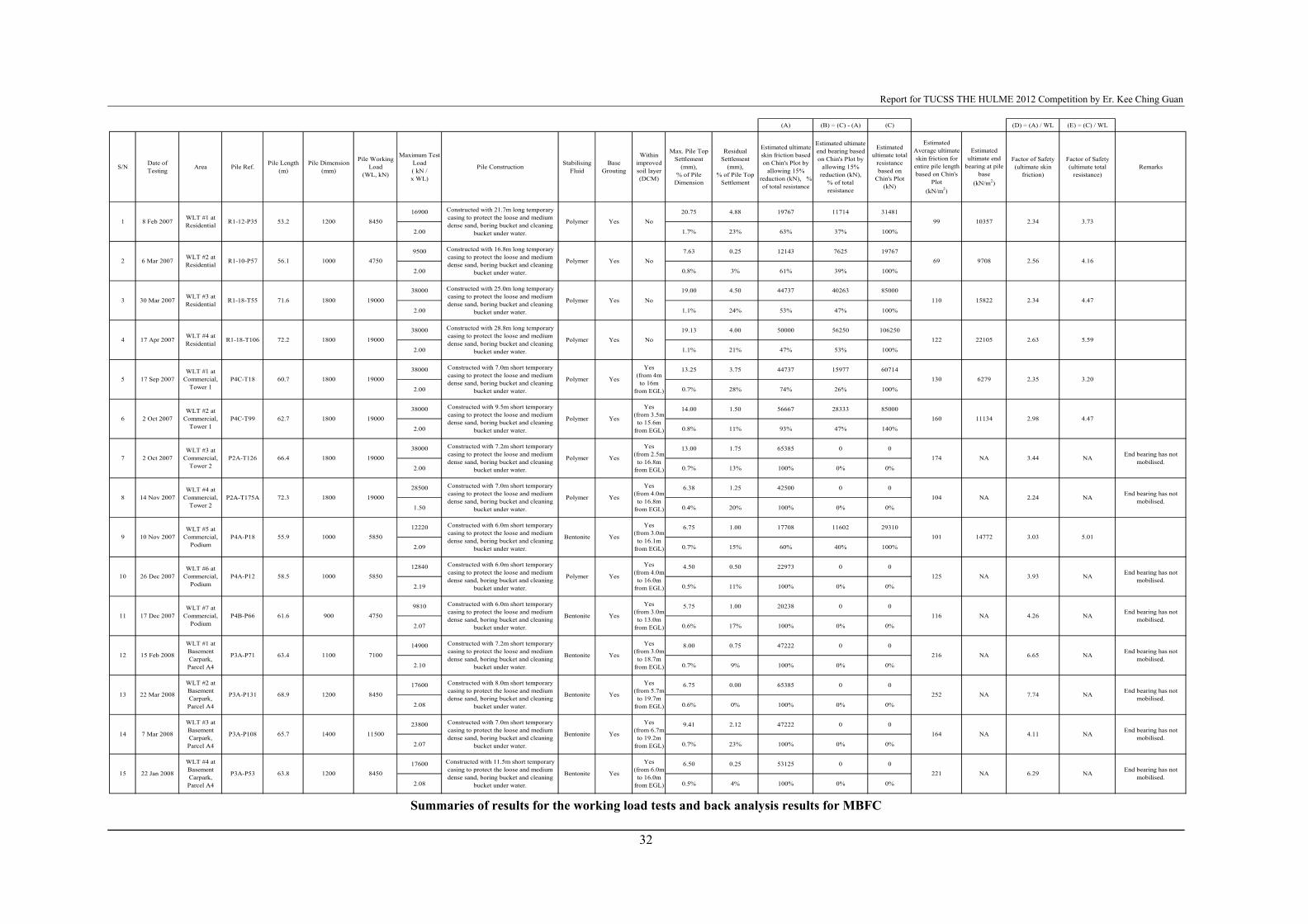
Total 15 numbers of working load tests had been carried out on the working piles
for MBFC to verify the pile performance. It is noted that all the piles had been base
grouted prior the working load tests. In addition, all the piles are located within the
soil improvement layer except those piles at R1. Therefore, the performances of the
piles are expected to be very good as per the discussion early on the effects of base
grouting and effects of improved soil layer. The author has carried out back analysis
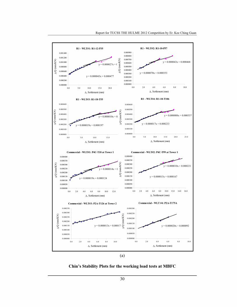
for the load tests on the working piles using Chin’s Stability Plot.
All the working load tests had been loaded to 2 times working load. The pile top
settlements for the four piles at R1, whereby the piles were located outside the
improved soil layer, were measured at 0.8% to 1.7% of pile dimension. Whereas,
the settlements for the 11 piles located within the improved soil layer had
experience lesser values, various from 0.4% to 0.8%. These results are comparable,
where 1.4% and 1.7% for R1-UTP01 and A2-UTP01 (with base grouting & outside
improved soil area) respectively & 0.5% of pile dimension for A2-UTP02 (with
based grouting & within improved soil area).
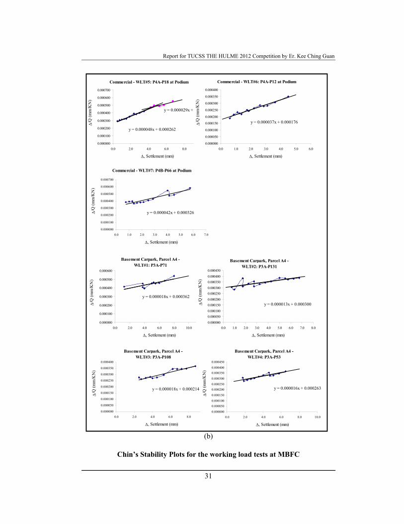
The estimated average ultimate skin frictions for the entire pile length based on
Chin’s Plot were also lesser, from 69 to 122kN/m2, for piles located outside the
improved soil area than the opposite with higher skin frictions from 101 to
252kN/m2. As mentioned earlier, all the piles had been base grouted before the load
tests. Generally, the skin frictions were only partially mobilised during the load tests
(2 x WL) and the end bearings were not mobilised or only slightly mobilised. The
factor of safeties for all the test piles, based on the estimate ultimate total resistance
and ultimate skin friction, are much higher than the design values of 2.5 and 2.0
respectively. These were shown clearly in the Chin’s Plots and the results on Table.
The results on the working test piles were agreeable with the previous on the effects
of improved soil layer and base grouting. Therefore, it could be concluded that
Report for TUCSS THE HULME 2012 Competition by Er. Kee Ching Guan
29
performance of the deep foundation in MBFC is extremely good and safe. However,
it also shows that the design of the bored piles was too conservative as resulted
from ignoring the both effects of base grouting and improved soil layer. In the
author’s opinion, the design should take into account on the effects of base grouting
and this would offer a more economical, safe and effective deep foundation system.
As for the other, the effects of improved soil layer shall not be considered in the
design as proposed by the author. The reasons are the effects of consolidation on the
piles would affect the contribution of improved soil layer and this would require
further study and research.
Report for TUCSS THE HULME 2012 Competition by Er. Kee Ching Guan
30
(a)
Chin’s Stability Plots for the working load tests at MBFC
R1 - WLT#1: R1-12-P35
y = 0.000043x + 0.000477
y = 0.000027x + 0.000649
0.000000
0.000200
0.000400
0.000600
0.000800
0.001000
0.001200
0.001400
0.0 5.0 10.0 15.0 20.0 25.0
Δ, Settlement (mm)
Δ/Q
(mm
/KN
)
R1 - WLT#2: R1-10-P57
y = 0.000070x + 0.000353
y = 0.000043x + 0.000468
0.0000000.000100
0.0002000.000300
0.0004000.000500
0.0006000.000700
0.0008000.000900
0.0 2.0 4.0 6.0 8.0 10.0
Δ, Settlement (mm)
Δ/Q
(mm
/KN
)
R1 - WLT#3: R1-18-T55
y = 0.000019x + 0.000197
y = 0.000010x + 0.000289
0.000000
0.000100
0.000200
0.000300
0.000400
0.000500
0.000600
0.0 5.0 10.0 15.0 20.0
Δ, Settlement (mm)
Δ/Q
(mm
/KN
)
R1 - WLT#4: R1-18-T106
y = 0.000017x + 0.000233
y = 0.000008x + 0.000337
0.000000
0.000100
0.000200
0.000300
0.000400
0.000500
0.000600
0.0 5.0 10.0 15.0 20.0 25.0
Δ, Settlement (mm)
Δ/Q
(mm
/KN
)
Commercial - WLT#1: P4C-T18 at Tower 1
y = 0.000019x + 0.000124
y = 0.000014x + 0.000161
0.000000
0.000050
0.000100
0.000150
0.000200
0.000250
0.000300
0.000350
0.000400
0.0 2.0 4.0 6.0 8.0 10.0 12.0 14.0
Δ, Settlement (mm)
Δ/Q
(mm
/KN
)
Commercial - WLT#2: P4C-T99 at Tower 1
y = 0.000015x + 0.000167
y = 0.000010x + 0.000221
0.000000
0.000050
0.000100
0.000150
0.000200
0.000250
0.000300
0.000350
0.000400
0.0 2.0 4.0 6.0 8.0 10.0 12.0 14.0 16.0
Δ, Settlement (mm)
Δ/Q
(mm
/KN
)
Commercial - WLT#3: P2A-T126 at Tower 2
y = 0.000013x + 0.000170
0.000000
0.000050
0.000100
0.000150
0.000200
0.000250
0.000300
0.000350
0.0 2.0 4.0 6.0 8.0 10.0 12.0
Δ, Settlement (mm)
Δ/Q
(mm
/KN
)
Commercial - WLT #4: P2A-T175A
y = 0.000020x + 0.000092
0.000000
0.000050
0.000100
0.000150
0.000200
0.000250
0.000300
0.0 2.0 4.0 6.0 8.0 10.0
Δ, Settlement (mm)
Δ/Q
(mm
/KN
)
Report for TUCSS THE HULME 2012 Competition by Er. Kee Ching Guan
31
(b)
Chin’s Stability Plots for the working load tests at MBFC
Commercial - WLT#5: P4A-P18 at Podium
y = 0.000048x + 0.000262
y = 0.000029x + 0.000348
0.000000
0.000100
0.000200
0.000300
0.000400
0.000500
0.000600
0.000700
0.0 2.0 4.0 6.0 8.0 10.0
Δ, Settlement (mm)
Δ/Q
(mm
/KN
)
Commercial - WLT#6: P4A-P12 at Podium
y = 0.000037x + 0.000176
0.000000
0.000050
0.000100
0.000150
0.000200
0.000250
0.000300
0.000350
0.000400
0.0 1.0 2.0 3.0 4.0 5.0 6.0
Δ, Settlement (mm)
Δ/Q
(mm
/KN
)
Commercial - WLT#7: P4B-P66 at Podium
y = 0.000042x + 0.000326
0.000000
0.000100
0.000200
0.000300
0.000400
0.000500
0.000600
0.000700
0.0 1.0 2.0 3.0 4.0 5.0 6.0 7.0
Δ, Settlement (mm)
Δ/Q
(mm
/KN
)
Basement Carpark, Parcel A4 - WLT#1: P3A-P71
y = 0.000018x + 0.000362
0.000000
0.000100
0.000200
0.000300
0.000400
0.000500
0.000600
0.0 2.0 4.0 6.0 8.0 10.0 12.0
Δ, Settlement (mm)
Δ/Q
(mm
/KN
)
Basement Carpark, Parcel A4 - WLT#2: P3A-P131
y = 0.000013x + 0.000300
0.0000000.0000500.0001000.0001500.0002000.0002500.0003000.0003500.0004000.000450
0.0 1.0 2.0 3.0 4.0 5.0 6.0 7.0 8.0
Δ, Settlement (mm)
Δ/Q
(mm
/KN
)
Basement Carpark, Parcel A4 - WLT#3: P3A-P108
y = 0.000018x + 0.000214
0.000000
0.000050
0.000100
0.000150
0.000200
0.000250
0.000300
0.000350
0.000400
0.0 2.0 4.0 6.0 8.0 10.0
Δ, Settlement (mm)
Δ/Q
(mm
/KN
)
Basement Carpark, Parcel A4 - WLT#4: P3A-P53
y = 0.000016x + 0.000263
0.000000
0.0000500.000100
0.000150
0.0002000.000250
0.000300
0.0003500.000400
0.000450
0.0 2.0 4.0 6.0 8.0 10.0
Δ, Settlement (mm)
Δ/Q
(mm
/KN
)
Report for TUCSS THE HULME 2012 Competition by Er. Kee Ching Guan
32
Summaries of results for the working load tests and back analysis results for MBFC
(A) (B) = (C) - (A) (C) (D) = (A) / WL (E) = (C) / WL
S/N Date of Testing Area Pile Ref. Pile Length
(m)Pile Dimension
(mm)
Pile Working Load
(WL, kN)
Maximum Test Load ( kN / x WL)
Pile Construction Stabilising Fluid
Base Grouting
Within improved soil layer (DCM)
Max. Pile Top Settlement
(mm), % of Pile
Dimension
Residual Settlement
(mm), % of Pile Top
Settlement
Estimated ultimate skin friction based on Chin's Plot by
allowing 15% reduction (kN), % of total resistance
Estimated ultimate end bearing based on Chin's Plot by
allowing 15% reduction (kN),
% of total resistance
Estimated ultimate total
resistance based on
Chin's Plot (kN)
Estimated Average ultimate skin friction for entire pile length based on Chin's
Plot (kN/m2)
Estimated ultimate end
bearing at pile base
(kN/m2)
Factor of Safety (ultimate skin
friction)
Factor of Safety (ultimate total
resistance)Remarks
16900 20.75 4.88 19767 11714 31481
2.00 1.7% 23% 63% 37% 100%
9500 7.63 0.25 12143 7625 19767
2.00 0.8% 3% 61% 39% 100%
2.00 1.1% 24% 53% 47% 100%
38000 19.13 4.00 50000 56250 106250
2.00 1.1% 21% 47% 53% 100%
38000 13.25 3.75 44737 15977 60714
2.00 0.7% 28% 74% 26% 100%
38000 14.00 1.50 56667 28333 85000
2.00 0.8% 11% 93% 47% 140%
38000 13.00 1.75 65385 0 0
2.00 0.7% 13% 100% 0% 0%
28500 6.38 1.25 42500 0 0
1.50 0.4% 20% 100% 0% 0%
12220 6.75 1.00 17708 11602 29310
2.09 0.7% 15% 60% 40% 100%
12840 4.50 0.50 22973 0 0
2.19 0.5% 11% 100% 0% 0%
9810 5.75 1.00 20238 0 0
2.07 0.6% 17% 100% 0% 0%
14900 8.00 0.75 47222 0 0
2.10 0.7% 9% 100% 0% 0%
17600 6.75 0.00 65385 0 0
2.08 0.6% 0% 100% 0% 0%
23800 9.41 2.12 47222 0 0
2.07 0.7% 23% 100% 0% 0%
17600 6.50 0.25 53125 0 0
2.08 0.5% 4% 100% 0% 0%
2.98
3.44
6.29
6.65
7.74
4.11
3.03
3.93
4.26
2.24
122
130
160
174
NA
NA
NA
NA
NA
End bearing has not mobilised.
3.73
4.16
4.47
5.59
3.20
4.47
NA
NA
5.01
Bentonite Yes
Yes (from 6.0m to 16.0m
from EGL)
NA22163.8 1200 8450
Constructed with 11.5m short temporary casing to protect the loose and medium dense sand, boring bucket and cleaning
bucket under water.
15 22 Jan 2008
WLT #4 at Basement Carpark,
Parcel A4
P3A-P53
Yes
Yes (from 6.7m to 19.2m
from EGL)
NA End bearing has not mobilised. 164
End bearing has not mobilised.
14 7 Mar 2008
WLT #3 at Basement Carpark,
Parcel A4
P3A-P108 65.7 1400 11500
Constructed with 7.0m short temporary casing to protect the loose and medium dense sand, boring bucket and cleaning
bucket under water.
Bentonite
Bentonite Yes
Yes (from 5.7m to 19.7m
from EGL)
NA25268.9 1200 8450
Constructed with 8.0m short temporary casing to protect the loose and medium dense sand, boring bucket and cleaning
bucket under water.
13 22 Mar 2008
WLT #2 at Basement Carpark,
Parcel A4
P3A-P131
Yes
Yes (from 3.0m to 18.7m
from EGL)
NA End bearing has not mobilised. 216
End bearing has not mobilised.
12 15 Feb 2008
WLT #1 at Basement Carpark,
Parcel A4
P3A-P71 63.4 1100 7100
Constructed with 7.2m short temporary casing to protect the loose and medium dense sand, boring bucket and cleaning
bucket under water.
Bentonite
Bentonite Yes
Yes (from 3.0m to 13.0m
from EGL)
NA11661.6 900 4750
Constructed with 6.0m short temporary casing to protect the loose and medium dense sand, boring bucket and cleaning
bucket under water.
11 17 Dec 2007WLT #7 at
Commercial, Podium
P4B-P66
Yes
Yes (from 4.0m to 16.0m
from EGL)
NA End bearing has not mobilised. NA12510 26 Dec 2007
WLT #6 at Commercial,
PodiumP4A-P12 58.5 1000 5850
Constructed with 6.0m short temporary casing to protect the loose and medium dense sand, boring bucket and cleaning
bucket under water.
Polymer
Bentonite Yes
Yes (from 3.0m to 16.1m
from EGL)
1477210155.9 1000 5850
Constructed with 6.0m short temporary casing to protect the loose and medium dense sand, boring bucket and cleaning
bucket under water.
9 10 Nov 2007WLT #5 at
Commercial, Podium
P4A-P18
Yes
Yes (from 4.0m to 16.8m
from EGL)
NA End bearing has not mobilised. 104
End bearing has not mobilised.
8 14 Nov 2007WLT #4 at
Commercial, Tower 2
P2A-T175A 72.3 1800 19000
Constructed with 7.0m short temporary casing to protect the loose and medium dense sand, boring bucket and cleaning
bucket under water.
Polymer
Polymer Yes
Yes (from 2.5m to 16.8m
from EGL)
NA
11134
7 2 Oct 2007WLT #3 at
Commercial, Tower 2
P2A-T126 66.4 1800 19000
Constructed with 7.2m short temporary casing to protect the loose and medium dense sand, boring bucket and cleaning
bucket under water.
1
2
34.50
WLT #1 at Residential
WLT #2 at Residential
WLT #3 at Residential
19.00
8 Feb 2007
6 Mar 2007
10357
9708
15822
2.34
2.56
2.34
2.63
85000
99
69
110
4 17 Apr 2007 WLT #4 at Residential R1-18-T106
5 17 Sep 2007WLT #1 at
Commercial, Tower 1
P4C-T18
72.2 1800 19000
60.7 1800 19000
30 Mar 2007
Constructed with 28.8m long temporary casing to protect the loose and medium dense sand, boring bucket and cleaning
bucket under water.
Constructed with 7.0m short temporary casing to protect the loose and medium dense sand, boring bucket and cleaning
bucket under water.
44737R1-18-T55 71.6 1800 19000
Constructed with 25.0m long temporary casing to protect the loose and medium dense sand, boring bucket and cleaning
bucket under water.
38000 40263
Polymer Yes
Yes (from 4m to 16m
from EGL)
Polymer Yes No
NoPolymer Yes
22105
6279 2.35
6 2 Oct 2007WLT #2 at
Commercial, Tower 1
P4C-T99 Polymer Yes
Yes (from 3.5m to 15.6m
from EGL)
4750
Constructed with 16.8m long temporary casing to protect the loose and medium dense sand, boring bucket and cleaning
bucket under water.
Polymer
62.7 1800 19000
Constructed with 9.5m short temporary casing to protect the loose and medium dense sand, boring bucket and cleaning
bucket under water.
1200
1000
8450
Constructed with 21.7m long temporary casing to protect the loose and medium dense sand, boring bucket and cleaning
bucket under water.
53.2R1-12-P35
R1-10-P57 56.1
Yes
Yes
Polymer No
No
Report for TUCSS THE HULME 2012 Competition by Er. Kee Ching Guan
33
Evaluation of Outcomes and Impacts
The project is situated at the Marina Bay, an artificial bay formed by reclamation,
which will be developed to further support Singapore’s continuing growth as a
major business and financial hub. Marina Bay Business Financial Centre is the first
few developments in this area. Future developments around Marina Bay would also
have the similarities as the current development, i.e. high rise buildings supported
by deep foundation and deep basements which required soil improvements works to
form the earth retaining or stabilising structure. Thus it was important to understand
the deep foundation and soil improvements behaviours and to develop more reliable
and economical in the design and construction methods in Marina Bay.
In this section, the author discussed the behaviour of the bored piles at MBFC. The
findings are useful and would have great impacts in the future projects if there are
adopted in the design and construction. The findings are summarised below:
Foundation bored piles
Effect of base grouting – Take into account of the contribution of base
grouting on the skin friction, i.e. base grouted pile shaft at 2D to 4D from
toe level, adopt 6~9N or 0.99 to 1.71 (β-value).
Impacts: Pile penetration depths would have been reduced by 10 to 30%,
that will save cost and construction duration.
Effect of DCM – Take into account of the contribution from the improved
soil layer, i.e. skin friction of 375kN/m2 for the pile shaft within the
improved soil layer.
Impacts: Pile penetration depths could be reduced.
Report for TUCSS THE HULME 2012 Competition by Er. Kee Ching Guan
34
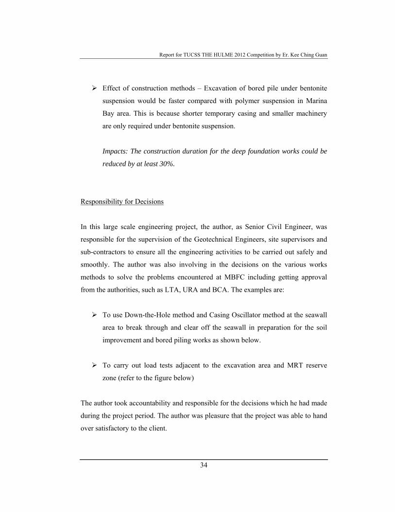
Effect of construction methods – Excavation of bored pile under bentonite
suspension would be faster compared with polymer suspension in Marina
Bay area. This is because shorter temporary casing and smaller machinery
are only required under bentonite suspension.
Impacts: The construction duration for the deep foundation works could be
reduced by at least 30%.
Responsibility for Decisions
In this large scale engineering project, the author, as Senior Civil Engineer, was
responsible for the supervision of the Geotechnical Engineers, site supervisors and
sub-contractors to ensure all the engineering activities to be carried out safely and
smoothly. The author was also involving in the decisions on the various works
methods to solve the problems encountered at MBFC including getting approval
from the authorities, such as LTA, URA and BCA. The examples are:
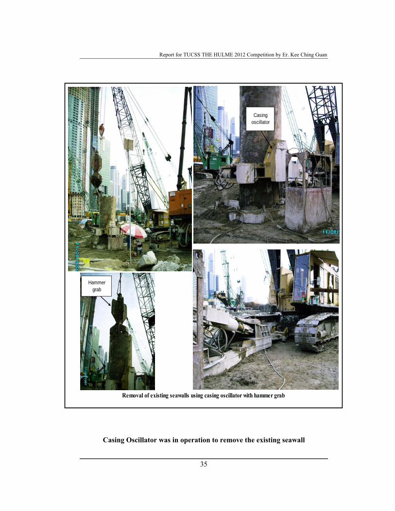
To use Down-the-Hole method and Casing Oscillator method at the seawall
area to break through and clear off the seawall in preparation for the soil
improvement and bored piling works as shown below.
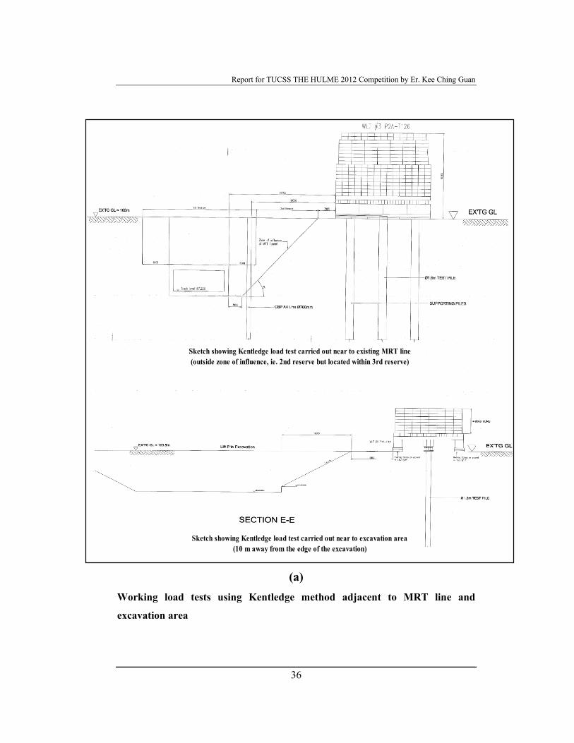
To carry out load tests adjacent to the excavation area and MRT reserve
zone (refer to the figure below)
The author took accountability and responsible for the decisions which he had made
during the project period. The author was pleasure that the project was able to hand
over satisfactory to the client.
Report for TUCSS THE HULME 2012 Competition by Er. Kee Ching Guan
35
Casing Oscillator was in operation to remove the existing seawall
Removal of existing seawalls using casing oscillator with hammer grab
Casing oscillator
Hammer grab
Report for TUCSS THE HULME 2012 Competition by Er. Kee Ching Guan
36
(a) Working load tests using Kentledge method adjacent to MRT line and
excavation area
Sketch showing Kentledge load test carried out near to existing MRT line (outside zone of influence, ie. 2nd reserve but located within 3rd reserve)
Sketch showing Kentledge load test carried out near to excavation area (10 m away from the edge of the excavation)
Report for TUCSS THE HULME 2012 Competition by Er. Kee Ching Guan
37
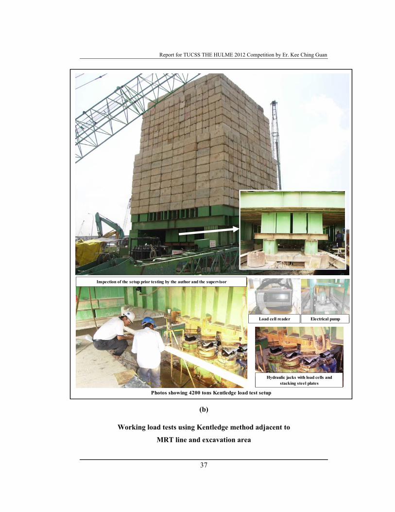
(b)
Working load tests using Kentledge method adjacent to
MRT line and excavation area
Photos showing 4200 tons Kentledge load test setup
Load cell reader Electrical pump
Hydraulic jacks with load cells and stacking steel plates
Inspection of the setup prior testing by the author and the supervisor
Report for TUCSS THE HULME 2012 Competition by Er. Kee Ching Guan
38
Managing Engineering Activities
This project involved a lot of engineering activities and all the activities would have
to be carried out closely and simultaneously. The engineering activities are:
Geotechnical instrumentation;
Deep cement mixing;
Jet grouting;
Bored piles;
Continuous bored piles;
Down-the-hole hammer;
Casing oscillator;
DCM coring tests.
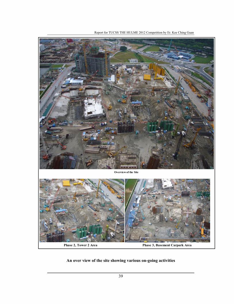
The overall view of the site can be seen in the following. Some of the activities are
shown. The author had to plan the daily activities based on 24-hour a day basis. The
aim was to avoid unnecessary down time for all the heavy machineries and man
powers from the sub-contractors. Various considerations had to be taken care for
the planning purpose. Such as, bored piles can only be installed after DCM has been
completed; effects of jet grouting on completed bored piles need to be taken into
considerations; etc.
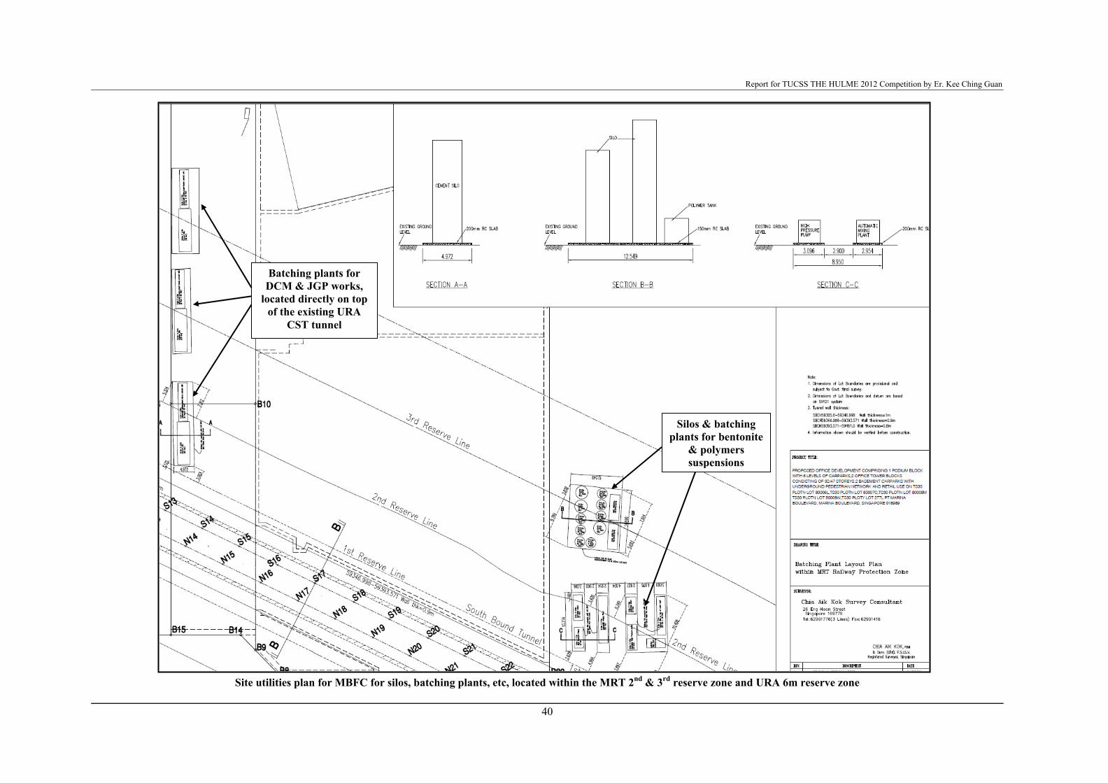
Site utilities plan was also a very important issue. This was because almost all the
engineering works located on the entire site. Allocation of utilities, such as water
pond, bentonite / polymer silos, cement silos, mixing plants, machineries, boring
tools, etc, was the great challenge in this particular site, whereby existing MRT line
and existing CST are located within the site boundary. Therefore, the site utilities
plan had to be cleared and approved by LTA & URA and to make sure that the
effects on the existing tunnels are minimal due to the additional loads created. The
site utilities plan is shown also.
Report for TUCSS THE HULME 2012 Competition by Er. Kee Ching Guan
39
An over view of the site showing various on-going activities
Phase 2, Tower 2 Area
Overview of the Site
Phase 3, Basement Carpark Area
Report for TUCSS THE HULME 2012 Competition by Er. Kee Ching Guan
40
Site utilities plan for MBFC for silos, batching plants, etc, located within the MRT 2nd & 3rd reserve zone and URA 6m reserve zone
Silos & batching plants for bentonite
& polymers suspensions
Batching plants for DCM & JGP works,
located directly on top of the existing URA
CST tunnel
Report for TUCSS THE HULME 2012 Competition by Er. Kee Ching Guan
41
Exercising Sound Judgement
The author had exercise sound judgement during his involvement in the project. He
worked together with all the professional personnel in the design and construction
of the deep foundation bored piles. He analysed the load tests results and confirmed
the design parameters with the fellow consultants for the construction of the
working piles. The design parameters were reasonably correct and all the load tests
on the working piles had passed according to the criteria. His analysis on the effects
of base grouting and DCM on the foundation bored piles could be continued with
the research and adopted in the future projects in Marina Bay area. By adopting this
approach, the design and construction of the deep foundation bored piles would be
more economical and safer. He was also exercised sound professional engineering
judgement for adopting of down-the-hole hammer and casing oscillator methods to
overcome the existing seawall problems in MBFC.
Communication
During the whole project period, the author communicated well with all range of
people, such as authorities, consultants, his colleagues at site, sub-contractors and
suppliers. He assisted his Project Manager in chairing the daily site meeting with all
the sub-contractors for all the site works. He also involved in the consultants’
progress and technical meetings to solve all the site issues. In addition, he played a
very proactive role in getting URA/LTA’s clearance for all the engineering works
within their protection zone.
Report for TUCSS THE HULME 2012 Competition by Er. Kee Ching Guan
42
CONCLUSION
The author describes his project involvement in the Project BFC. The effects of
base grouting on the deep foundation bored piles are heavily described. The impacts
of the outcome of the current analysis could have great impact in the future’s deep
foundation design in Singapore.
31 July 2012