Embed Size (px)
Citation preview

JK Geotechnics GEOTECHNICAL & ENVIRONMENTAL ENGINEERS
PO Box 976, North Ryde BC NSW 1670 Tel: 02 9888 5000 Fax: 02 9888 5003 www.jkgeotechnics.com.au
Jeffery & Katauskas Pty Ltd, trading as JK Geotechnics ABN 17 003 550 801
REPORT
TO
NSW DEPARTMENT OF EDUCATION
C/- HAYBALL
ON
GEOTECHNICAL INVESTIGATION
FOR
PROPOSED ALTERATIONS AND ADDITIONS
AT
QUAKERS HILL EAST PUBLIC SCHOOL
14 CHASE DRIVE, ACACIA GARDENS, NSW
6 January 2017
Ref: 29855Zrpt

29855Zrpt Page ii
Date: 6 January 2017 Report No: 29855Zrpt Revision No: 0 Report prepared by: Agi Zenon Principal I Geotechnical Engineer For and on behalf of
JK GEOTECHNICS
PO Box 976
NORTH RYDE BC NSW 1670
Document Copyright of JK Geotechnics.
This Report (which includes all attachments and annexures) has been prepared by JK Geotechnics (JKG) for its Client, and is intended for the use only by that Client. This Report has been prepared pursuant to a contract between JKG and its Client and is therefore subject to:
a) JKG’s proposal in respect of the work covered by the Report;
b) the limitations defined in the Client’s brief to JKG;
c) the terms of contract between JK and the Client, including terms limiting the liability of JKG. If the Client, or any person, provides a copy of this Report to any third party, such third party must not rely on this Report, except with the express written consent of JKG which, if given, will be deemed to be upon the same terms, conditions, restrictions and limitations as apply by virtue of (a), (b), and (c) above. Any third party who seeks to rely on this Report without the express written consent of JKG does so entirely at their own risk and to the fullest extent permitted by law, JKG accepts no liability whatsoever, in respect of any loss or damage suffered by any such third party. At the Company’s discretion, JKG may send a paper copy of this report for confirmation. In the event of any discrepancy between paper and electronic versions, the paper version is to take precedence. The USER shall ascertain the accuracy and the suitability of this information for the purpose intended; reasonable effort is made at the time of assembling this information to ensure its integrity. The recipient is not authorised to modify the content of the information supplied without the prior written consent of JKG.

29855Zrpt Page iii
TABLE OF CONTENTS
1 INTRODUCTION 1
2 INVESTIGATION PROCEDURE 2
3 RESULTS OF INVESTIGATION 3
3.1 Site Description 3
3.2 Subsurface Conditions 3
3.3 Laboratory Test Results 4
4 COMMENTS AND RECOMMENDATIONS 4
4.1 Site Preparation 4
4.2 Footings 4
4.2.1 Site Classification 4
4.2.2 High Level Footings 5
4.2.3 Pile Footings 5
4.3 On-Grade Floor Slabs 6
4.4 External Walkway Slabs 6
4.5 Further Geotechnical Input 7
5 SALINITY 7
6 GENERAL COMMENTS 7
STS TABLE A: MOISTURE CONTENT, ATTERBERG LIMITS & LINEAR SHRINKAGE TEST REPORT
BOREHOLE LOGS 1 TO 3
FIGURE 1: SITE LOCATION PLAN
FIGURE 2: BOREHOLE LOCATION PLAN
REPORT EXPLANATION NOTES

29855Zrpt Page 1
1 INTRODUCTION
This report presents the results of a geotechnical investigation for the proposed alterations and
additions at Quakers Hill East Public School, 14 Chase Drive, Acacia Gardens, NSW. A site location
plan is attached as Figure 1. The investigation was commissioned by Hayball, on behalf of the NSW
Department of Education. The commission was in accordance with our proposal (Ref P43202Zrpt)
dated 24 August 2016.
We understand from the provided Concept Design Option 7, prepared by Hayball, that the proposed
alterations and additions will include:
A two storey building over the eastern portion of the school premises for 12 Home Bases,
Amenities, Special Programs, and mini Library.
Covered walkways along the length of the above building and linking with the existing
buildings to the south and west.
A staff extension over the south-western portion of the school premises.
Areas of possible future work are also indicated to the north and west of the above proposed two
storey building. We have assumed that typical loads for these types of structures apply.
The purpose of the investigation was to obtain geotechnical information on subsurface conditions
at three client nominated borehole locations, as a basis for comments and recommendations on
the geotechnical aspects of the proposed alterations and additions.
Our environmental division, Environmental Investigation Services (EIS), was commissioned to carry
out a contamination investigation concurrently with the geotechnical investigation. The EIS report
(E29855KP) must be read in conjunction with our geotechnical report.

29855Zrpt Page 2
2 INVESTIGATION PROCEDURE
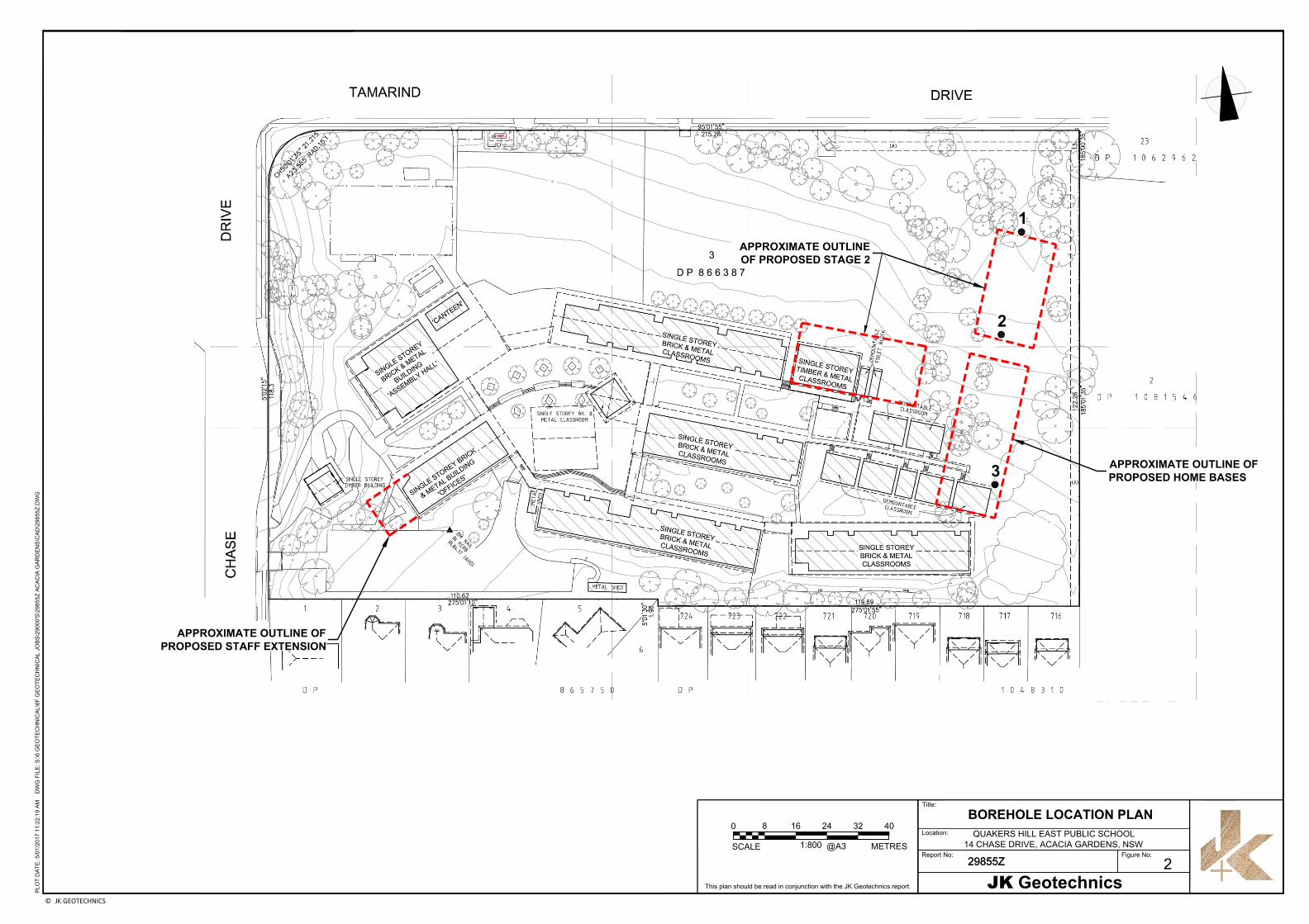
The fieldwork for the investigation was carried out on 8 December 2016 and comprised three
boreholes (BH1 to BH3) formed with a push tube to depths of 2.1m and 2.5m using our 4x4 wheel
drive Eziprobe rig. The borehole locations, as indicated on attached Figure 2, were set out as close
as practical to the nominated locations using taped measurements from existing surface features,
and were electromagnetically scanned for buried services prior to probing commencing.
The surface reduced levels (RLs) at the borehole locations were estimated by interpolation between
ground contours and spot heights shown on the provided survey plans (Ref 43782D7, Sheets 1/5
to 5/5, dated 4/10/16) prepared by LTS Lockley, and are therefore approximate. Survey plan 1/5
forms the basis of Figure 2 and the survey datum is the Australian Height Datum (AHD).
The nature and composition of the subsurface soil and rock strata were assessed by logging the
materials recovered in the push tube sampler. The strength of the subsoils was assessed from
hand penetrometer readings on clayey samples recovered in the push tube sampler. The strength
of the bedrock was assessed based on resistance to push tube advance and examination of the
recovered rock fragments. Groundwater observations were made on completion of individual
boreholes. Long term groundwater monitoring was not carried out.
Our geotechnical engineer was present full time on site during the fieldwork and set out the borehole
locations, directed the electromagnetic scan, nominated sampling and testing, and logged the
subsurface profile. The borehole logs are presented with this report. The Report Explanation Notes
include a glossary on the logging terms and symbols used.
A representative soil sample was recovered from site and submitted to the Soil Test Services Pty
Ltd (STS) NATA registered laboratory for moisture content, Atterberg Limits and linear shrinkage
testing. The test results are summarised in attached STS Table A.

29855Zrpt Page 3
3 RESULTS OF INVESTIGATION
3.1 Site Description
The site is located over the eastern end of the Quakers Hill East Public School premises in
undulating topography below the crest of a north-east facing hillside. The site area slopes down to
the north at 2 to 4. Tamarind Drive bounds the site along the north.
At the time of the investigation, the site area was generally vacant with a patchy grass cover and
numerous trees.
To the south and south-west of the site were single storey permanent and demountable school
buildings. To the east was dense bushland. Residential properties were located to the south beyond
the school boundary.
The ‘dial before you dig’ drawings indicate the presence of a buried sewer adjacent to, and just
within, the eastern school boundary.
3.2 Subsurface Conditions
The published 1:100,000 geological map of Penrith indicates that the site is underlain by Bringelly
Shales of the Wianamatta Group. The investigation has revealed a generalised subsurface profile
comprising surficial fill over residual silty clay, with shale bedrock at relatively shallow depth.
Groundwater was not encountered within the 2.5m investigation depth. For detailed subsurface
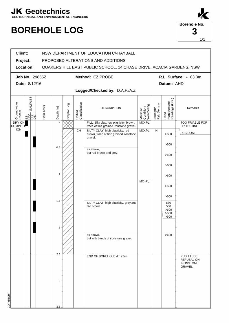
conditions at specific locations, reference should be made to the borehole logs. A summary of the
subsurface conditions, as encountered, is presented below:
Fill comprising silty clay of variable plasticity was encountered from the surface of all three
boreholes and extended to depths between 0.15m (BH3) and 0.5m (BH2). The fill often
contained ironstone and igneous gravel.
Residual silty clay of high plasticity and hard strength was encountered below the fill in all
three boreholes. The push tube in BH2 and BH3 refused on ironstone gravel within, or at the
base of, the residual silty clay at depths of 2.5m.
Weathered shale bedrock was encountered at a depth of 1.9m, below the residual silty clay,
in BH1 only. The shale was assessed to be extremely weathered and of extremely low
strength. The push tube refused in the shale after 0.2m penetration.

29855Zrpt Page 4
Groundwater was not encountered and all three boreholes were ‘dry’ during and on
completion of forming individual boreholes. We note that the groundwater levels may not have
stabilised during the limited observation period. Long term groundwater monitoring was not
carried out.
We note that the above subsurface conditions are typical for Western Sydney and very similar to
those encountered during previous geotechnical investigations in the vicinity.
3.3 Laboratory Test Results
The laboratory test results have confirmed our field classification, including the high plasticity, of
the residual silty clays. The test results have also indicated that the residual silty clays have a high
shrink-swell reactivity.
4 COMMENTS AND RECOMMENDATIONS
4.1 Site Preparation
Site preparation for the proposed buildings and covered walkways will require the removal of a
number of trees. Stripping of vegetation and topsoil will also be required. Following this, any obvious
deleterious or contaminated existing fill should be removed. The topsoil should be separately
stockpiled for possible use for landscaping.
The site can then be excavated to suit the design subgrade levels of the development.
Reference should be made to the EIS report and to Section 5 below for guidance on the offsite
disposal of soils.
4.2 Footings
4.2.1 Site Classification
Based on the investigation results, the site classifies as ‘Class H1’ in accordance with AS2870.
However, the presence of trees over the eastern end of the school premises and the removal of
some of these trees will result in a more severe ‘H2’ site classification being applicable in this area.
We note, however, that AS2870 does not apply for the proposed structures. The Standard can,
however, be used for guidance.
29855Zrpt Page 5
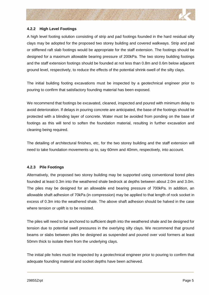
4.2.2 High Level Footings
A high level footing solution consisting of strip and pad footings founded in the hard residual silty
clays may be adopted for the proposed two storey building and covered walkways. Strip and pad
or stiffened raft slab footings would be appropriate for the staff extension. The footings should be
designed for a maximum allowable bearing pressure of 200kPa. The two storey building footings
and the staff extension footings should be founded at not less than 0.8m and 0.6m below adjacent
ground level, respectively, to reduce the effects of the potential shrink-swell of the silty clays.
The initial building footing excavations must be inspected by a geotechnical engineer prior to
pouring to confirm that satisfactory founding material has been exposed.
We recommend that footings be excavated, cleaned, inspected and poured with minimum delay to
avoid deterioration. If delays in pouring concrete are anticipated, the base of the footings should be
protected with a blinding layer of concrete. Water must be avoided from ponding on the base of
footings as this will tend to soften the foundation material, resulting in further excavation and
cleaning being required.
The detailing of architectural finishes, etc, for the two storey building and the staff extension will
need to take foundation movements up to, say 60mm and 40mm, respectively, into account.
4.2.3 Pile Footings
Alternatively, the proposed two storey building may be supported using conventional bored piles
founded at least 0.3m into the weathered shale bedrock at depths between about 2.0m and 3.0m.
The piles may be designed for an allowable end bearing pressure of 700kPa. In addition, an
allowable shaft adhesion of 70kPa (in compression) may be applied to that length of rock socket in
excess of 0.3m into the weathered shale. The above shaft adhesion should be halved in the case
where tension or uplift is to be resisted.
The piles will need to be anchored to sufficient depth into the weathered shale and be designed for
tension due to potential swell pressures in the overlying silty clays. We recommend that ground
beams or slabs between piles be designed as suspended and poured over void formers at least
50mm thick to isolate them from the underlying clays.
The initial pile holes must be inspected by a geotechnical engineer prior to pouring to confirm that
adequate founding material and socket depths have been achieved.

29855Zrpt Page 6
Groundwater inflow may occur into bored pile holes but we anticipate that the inflow will be
controllable by conventional pumping methods. The bored piles should be drilled, cleaned,
inspected and poured with minimal delay (ie. all on the same day).
4.3 On-Grade Floor Slabs
The ground floor slab to the proposed two storey building will overlie a soil profile which will be
subject to shrink-swell movements associated with the lower end of a ‘Class H2’ site. The floor slab
to the staff extension will underlie a soil profile which will be subject to shrink-swell movement
associated with ‘Class H1’ site.
Unless incorporated into a raft slab, we recommend that the above ground floor slabs be designed
as suspended between footings and poured over a void former a minimum of 50mm thick to isolate
them from the underlying clays. The detailing of floor slabs to accommodate shrink-swell
movements of even smaller magnitude so as to avoid damage is extremely difficult. In accordance
with AS2870, slab-on-grade internal floors are not appropriate for ‘Class M’ and more severe sites.
4.4 External Walkway Slabs
The proposed covered walkway pavements may be designed as slab-on-grade, provided the site
preparation outlined below is first completed.
Following excavation to the design subgrade levels, as described in Section 4.1 above, the exposed
clay subgrade should be proof-rolled using a 0.5 tonne static smooth drum roller. Proof-rolling
should be carried out under the direction of an experienced earthworks foreman or geotechnician
to assist in the detection of unstable areas. Any unstable areas so identified must be locally
excavated down to a stable base and replaced with well compacted site won clay.
We note that the clay subgrade may soften with an increase in moisture content. Therefore, good
and effective site drainage should be provided during construction and for long term site
maintenance. The principal aim of the drainage is to promote run-off and reduce ponding.
We recommend that if soil softening occurs, the subgrade should be over-excavated to below the
depth of moisture softening and that the excavated material be replaced with well compacted fill.
Consideration should be given to supporting concrete walkway slabs on a subbase layer of DBG20
or similar, compacted to 98% of Standard Maximum Dry Density (SMDD). The subbase material
will protect the clay subgrade and would provide more uniform slab support.
29855Zrpt Page 7
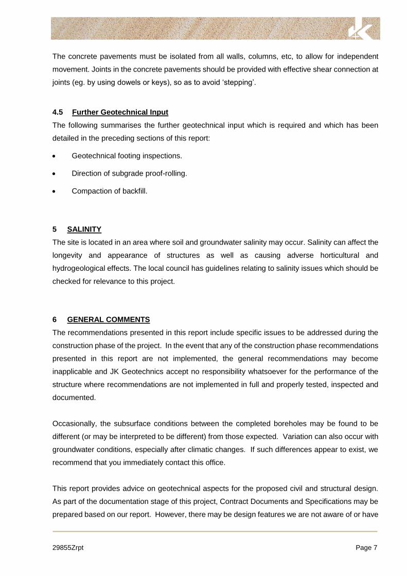
The concrete pavements must be isolated from all walls, columns, etc, to allow for independent
movement. Joints in the concrete pavements should be provided with effective shear connection at
joints (eg. by using dowels or keys), so as to avoid ‘stepping’.
4.5 Further Geotechnical Input
The following summarises the further geotechnical input which is required and which has been
detailed in the preceding sections of this report:
Geotechnical footing inspections.
Direction of subgrade proof-rolling.
Compaction of backfill.
5 SALINITY
The site is located in an area where soil and groundwater salinity may occur. Salinity can affect the
longevity and appearance of structures as well as causing adverse horticultural and
hydrogeological effects. The local council has guidelines relating to salinity issues which should be
checked for relevance to this project.
6 GENERAL COMMENTS
The recommendations presented in this report include specific issues to be addressed during the
construction phase of the project. In the event that any of the construction phase recommendations
presented in this report are not implemented, the general recommendations may become
inapplicable and JK Geotechnics accept no responsibility whatsoever for the performance of the
structure where recommendations are not implemented in full and properly tested, inspected and
documented.
Occasionally, the subsurface conditions between the completed boreholes may be found to be
different (or may be interpreted to be different) from those expected. Variation can also occur with
groundwater conditions, especially after climatic changes. If such differences appear to exist, we
recommend that you immediately contact this office.
This report provides advice on geotechnical aspects for the proposed civil and structural design.
As part of the documentation stage of this project, Contract Documents and Specifications may be
prepared based on our report. However, there may be design features we are not aware of or have

29855Zrpt Page 8
not commented on for a variety of reasons. The designers should satisfy themselves that all the
necessary advice has been obtained. If required, we could be commissioned to review the
geotechnical aspects of contract documents to confirm the intent of our recommendations has been
correctly implemented.
A waste classification will need to be assigned to any soil excavated from the site prior to offsite
disposal. Subject to the appropriate testing, material can be classified as Virgin Excavated Natural
Material (VENM), General Solid, Restricted Solid or Hazardous Waste. Analysis takes seven to
10 working days to complete, therefore, an adequate allowance should be included in the
construction program unless testing is completed prior to construction. If contamination is
encountered, then substantial further testing (and associated delays) should be expected.
We strongly recommend that this issue is addressed prior to the commencement of excavation on
site.
This report has been prepared for the particular project described and no responsibility is accepted
for the use of any part of this report in any other context or for any other purpose. If there is any
change in the proposed development described in this report then all recommendations should be
reviewed. Copyright in this report is the property of JK Geotechnics. We have used a degree of
care, skill and diligence normally exercised by consulting engineers in similar circumstances and
locality. No other warranty expressed or implied is made or intended. Subject to payment of all
fees due for the investigation, the client alone shall have a licence to use this report. The report
shall not be reproduced except in full.


0
0.5
1
1.5
2
2.5
3
3.5
DRY ONCOMPLET-
ION
CH
-
FILL: Silty clay, medium plasticity,grey brown and orange brown, traceof fine grained sand.
SILTY CLAY: high plasticity, brownand orange brown, trace of finegrained ironstone gravel.
as above,but grey and red brown.
SHALE: grey and red brown.
END OF BOREHOLE AT 2.1m
MC<PL
MC<PL
XW
H
EL
>600
>600
>600
>600
>600
500530
>600>600
RESIDUAL
HIGH PUSH TUBERESISTANCE
PUSH TUBEREFUSAL
JK GeotechnicsGEOTECHNICAL AND ENVIRONMENTAL ENGINEERS
BOREHOLE LOGBorehole No.
1
Client: NSW DEPARTMENT OF EDUCATION C/-HAYBALL
Project: PROPOSED ALTERATIONS AND ADDITIONS
Location: QUAKERS HILL EAST PUBLIC SCHOOL, 14 CHASE DRIVE, ACACIA GARDENS, NSW
Job No. 29855Z Method: EZIPROBE R.L. Surface: » 80.9m
Date: 8/12/16 Datum: AHD
Logged/Checked by: D.A.F./A.Z.
Gro
un
dw
ate
rR
eco
rd
ES
SA
MP
LE
SU
50
DB
DS
Fie
ld T
est
s
De
pth
(m
)
Gra
ph
ic L
og
Un
ifie
dC
lass
ifica
tion
DESCRIPTION
Mo
istu
reC
on
diti
on
/W
ea
the
ring
Str
en
gth
/R
el.
De
nsi
ty
Ha
nd
Pe
ne
tro
me
ter
Re
ad
ing
s (k
Pa
.)
Remarks
CO
PY
RIG
HT
1/1

0
0.5
1
1.5
2
2.5
3
3.5
DRY ONCOMPLET-
ION
CH
FILL: Silty clay, medium to highplasticity, grey and orange brown,trace of fine grained ironstone gravel,and fine to medium grained igneousgravel.FILL: Silty clay, low plasticity, brown,trace of fine grained ironstone gravel.
SILTY CLAY: high plasticity, redbrown and brown.
SILTY CLAY: high plasticity, grey andred brown, with ironstone gravelbands.
END OF BOREHOLE AT 2.5m
MC<PL
H >600
>600
>600
>600
>600
>600
>600
>600
>600
>600
>600
MULCH COVER
TOO FRIABLE FORHP TESTING
RESIDUAL
PUSH TUBEREFUSAL
JK GeotechnicsGEOTECHNICAL AND ENVIRONMENTAL ENGINEERS
BOREHOLE LOGBorehole No.
2
Client: NSW DEPARTMENT OF EDUCATION C/-HAYBALL
Project: PROPOSED ALTERATIONS AND ADDITIONS
Location: QUAKERS HILL EAST PUBLIC SCHOOL, 14 CHASE DRIVE, ACACIA GARDENS, NSW
Job No. 29855Z Method: EZIPROBE R.L. Surface: » 81.7m
Date: 8/12/16 Datum: AHD
Logged/Checked by: D.A.F./A.Z.
Gro
un
dw
ate
rR
eco
rd
ES
SA
MP
LE
SU
50
DB
DS
Fie
ld T
est
s
De
pth
(m
)
Gra
ph
ic L
og
Un
ifie
dC
lass
ifica
tion
DESCRIPTION
Mo
istu
reC
on
diti
on
/W
ea
the
ring
Str
en
gth
/R
el.
De
nsi
ty
Ha
nd
Pe
ne
tro
me
ter
Re
ad
ing
s (k
Pa
.)
Remarks
CO
PY
RIG
HT
1/1
0
0.5
1
1.5
2
2.5
3
3.5
DRY ONCOMPLET-
ION CH
FILL: Silty clay, low plasticity, brown,trace of fine grained ironstone gravel.
SILTY CLAY: high plasticity, redbrown, trace of fine grained ironstonegravel.
as above,but red brown and grey.
SILTY CLAY: high plasticity, grey andred brown.
as above,but with bands of ironstone gravel.
END OF BOREHOLE AT 2.5m
MC<PL
MC<PL
MC»PL
H>600
>600
>600
>600
>600
>600
>600
580550
>600>600>600
>600
TOO FRIABLE FORHP TESTING
RESIDUAL
PUSH TUBEREFUSAL ONIRONSTONEGRAVEL
JK GeotechnicsGEOTECHNICAL AND ENVIRONMENTAL ENGINEERS
BOREHOLE LOGBorehole No.
3
Client: NSW DEPARTMENT OF EDUCATION C/-HAYBALL
Project: PROPOSED ALTERATIONS AND ADDITIONS
Location: QUAKERS HILL EAST PUBLIC SCHOOL, 14 CHASE DRIVE, ACACIA GARDENS, NSW
Job No. 29855Z Method: EZIPROBE R.L. Surface: » 83.3m
Date: 8/12/16 Datum: AHD
Logged/Checked by: D.A.F./A.Z.
Gro
un
dw
ate
rR
eco
rd
ES
SA
MP
LE
SU
50
DB
DS
Fie
ld T
est
s
De
pth
(m
)
Gra
ph
ic L
og
Un
ifie
dC
lass
ifica
tion
DESCRIPTION
Mo
istu
reC
on
diti
on
/W
ea
the
ring
Str
en
gth
/R
el.
De
nsi
ty
Ha
nd
Pe
ne
tro
me
ter
Re
ad
ing
s (k
Pa
.)
Remarks
CO
PY
RIG
HT
1/1

AERIAL IMAGE SOURCE: GOOGLE EARTH PRO 7.1.5.1557
AERIAL IMAGE ©: 2015 GOOGLE INC.
PLO
T D
AT
E: 16/12/2016 5:22:52 P
M D
WG
F
ILE
: S
:\6 G
EO
TE
CH
NIC
AL\6F
G
EO
TE
CH
NIC
AL JO
BS
\29000'S
\29855Z
A
CA
CIA
G
AR
DE
NS
\C
AD
\29855Z
.D
WG
SITE
© JK GEOTECHNICS
29855Z
This plan should be read in conjunction with the JK Geotechnics report.
Report No:
Location:
Title:
QUAKERS HILL EAST PUBLIC SCHOOL
14 CHASE DRIVE, ACACIA GARDENS, NSW
29855Z
JK Geotechnics
Figure No:
SITE LOCATION PLAN
1
SOURCE: http://www.whereis.com/
PARRAMATTA
RIVER
SITE
3
2
1
PL
OT
D
AT
E: 5
/0
1/2
01
7 1
1:2
2:1
9 A
M D
WG
F
IL
E: S
:\6
G
EO
TE
CH
NIC
AL
\6
F G
EO
TE
CH
NIC
AL
JO
BS
\2
90
00
'S
\2
98
55
Z A
CA
CIA
G
AR
DE
NS
\C
AD
\2
98
55
Z.D
WG
0
SCALE@A3
8 16 24 32 40
1:800
METRES
Report No:
29855Z
Location:
Title:
QUAKERS HILL EAST PUBLIC SCHOOL
14 CHASE DRIVE, ACACIA GARDENS, NSW
29855Z
JK Geotechnics
© JK GEOTECHNICS
Figure No:
This plan should be read in conjunction with the JK Geotechnics report.
BOREHOLE LOCATION PLAN
2
APPROXIMATE OUTLINE
OF PROPOSED STAGE 2
APPROXIMATE OUTLINE OF
PROPOSED HOME BASES
APPROXIMATE OUTLINE OF
PROPOSED STAFF EXTENSION

Jeffery & Katauskas Pty Ltd, trading as JK Geotechnics ABN 17 003 550 801
REPORT EXPLANATION NOTES Dec16 Page 1 of 4
REPORT EXPLANATION NOTES
INTRODUCTION
These notes have been provided to amplify the geotechnical report in regard to classification methods, field procedures and certain matters relating to the Comments and Recommendations section. Not all notes are necessarily relevant to all reports.
The ground is a product of continuing natural and man-made processes and therefore exhibits a variety of characteristics and properties which vary from place to place and can change with time. Geotechnical engineering involves gathering and assimilating limited facts about these characteristics and properties in order to understand or predict the behaviour of the ground on a particular site under certain conditions. This report may contain such facts obtained by inspection, excavation, probing, sampling, testing or other means of investigation. If so, they are directly relevant only to the ground at the place where and time when the investigation was carried out.
DESCRIPTION AND CLASSIFICATION METHODS
The methods of description and classification of soils and rocks used in this report are based on Australian Standard 1726, the SAA Site Investigation Code. In general, descriptions cover the following properties – soil or rock type, colour, structure, strength or density, and inclusions. Identification and classification of soil and rock involves judgement and the Company infers accuracy only to the extent that is common in current geotechnical practice.
Soil types are described according to the predominating particle size and behaviour as set out in the attached Unified Soil Classification Table qualified by the grading of other particles present (eg. sandy clay) as set out below:
Soil Classification Particle Size
Clay
Silt
Sand
Gravel
less than 0.002mm
0.002 to 0.06mm
0.06 to 2mm
2 to 60mm
Non-cohesive soils are classified on the basis of relative density, generally from the results of Standard Penetration Test (SPT) as below:
Relative Density SPT ‘N’ Value (blows/300mm)
Very loose
Loose
Medium dense
Dense
Very Dense
less than 4
4 – 10
10 – 30
30 – 50
greater than 50
Cohesive soils are classified on the basis of strength (consistency) either by use of hand penetrometer, laboratory testing or engineering examination. The strength terms are defined as follows.
Classification Unconfined Compressive Strength kPa
Very Soft
Soft
Firm
Stiff
Very Stiff
Hard
Friable
less than 25
25 – 50
50 – 100
100 – 200
200 – 400
Greater than 400
Strength not attainable
– soil crumbles
Rock types are classified by their geological names, together with descriptive terms regarding weathering, strength, defects, etc. Where relevant, further information regarding rock classification is given in the text of the report. In the Sydney Basin, ‘Shale’ is used to describe thinly bedded to laminated siltstone. SAMPLING
Sampling is carried out during drilling or from other excavations to allow engineering examination (and laboratory testing where required) of the soil or rock.
Disturbed samples taken during drilling provide information on plasticity, grain size, colour, moisture content, minor constituents and, depending upon the degree of disturbance, some information on strength and structure. Bulk samples are similar but of greater volume required for some test procedures.
Undisturbed samples are taken by pushing a thin-walled sample tube, usually 50mm diameter (known as a U50), into the soil and withdrawing it with a sample of the soil contained in a relatively undisturbed state. Such samples yield information on structure and strength, and are necessary for laboratory determination of shear strength and compressibility. Undisturbed sampling is generally effective only in cohesive soils.
Details of the type and method of sampling used are given on the attached logs. INVESTIGATION METHODS
The following is a brief summary of investigation methods currently adopted by the Company and some comments on their use and application. All except test pits, hand auger drilling and portable dynamic cone penetrometers require the use of a mechanical drilling rig which is commonly mounted on a truck chassis.
JK Geotechnics GEOTECHNICAL & ENVIRONMENTAL ENGINEERS
REPORT EXPLANATION NOTES Dec16 Page 2 of 4
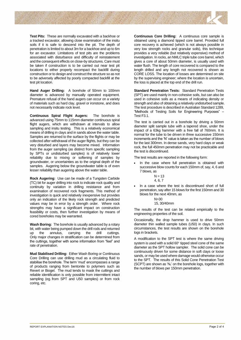
Test Pits: These are normally excavated with a backhoe or
a tracked excavator, allowing close examination of the insitu soils if it is safe to descend into the pit. The depth of penetration is limited to about 3m for a backhoe and up to 6m for an excavator. Limitations of test pits are the problems associated with disturbance and difficulty of reinstatement and the consequent effects on close-by structures. Care must be taken if construction is to be carried out near test pit locations to either properly recompact the backfill during construction or to design and construct the structure so as not to be adversely affected by poorly compacted backfill at the test pit location. Hand Auger Drilling: A borehole of 50mm to 100mm
diameter is advanced by manually operated equipment. Premature refusal of the hand augers can occur on a variety of materials such as hard clay, gravel or ironstone, and does not necessarily indicate rock level. Continuous Spiral Flight Augers: The borehole is
advanced using 75mm to 115mm diameter continuous spiral flight augers, which are withdrawn at intervals to allow sampling and insitu testing. This is a relatively economical means of drilling in clays and in sands above the water table. Samples are returned to the surface by the flights or may be collected after withdrawal of the auger flights, but they can be very disturbed and layers may become mixed. Information from the auger sampling (as distinct from specific sampling by SPTs or undisturbed samples) is of relatively lower reliability due to mixing or softening of samples by groundwater, or uncertainties as to the original depth of the samples. Augering below the groundwater table is of even lesser reliability than augering above the water table. Rock Augering: Use can be made of a Tungsten Carbide
(TC) bit for auger drilling into rock to indicate rock quality and continuity by variation in drilling resistance and from examination of recovered rock fragments. This method of investigation is quick and relatively inexpensive but provides only an indication of the likely rock strength and predicted values may be in error by a strength order. Where rock strengths may have a significant impact on construction feasibility or costs, then further investigation by means of cored boreholes may be warranted. Wash Boring: The borehole is usually advanced by a rotary
bit, with water being pumped down the drill rods and returned up the annulus, carrying the drill cuttings. Only major changes in stratification can be determined from the cuttings, together with some information from “feel” and rate of penetration. Mud Stabilised Drilling: Either Wash Boring or Continuous
Core Drilling can use drilling mud as a circulating fluid to stabilise the borehole. The term ‘mud’ encompasses a range of products ranging from bentonite to polymers such as Revert or Biogel. The mud tends to mask the cuttings and reliable identification is only possible from intermittent intact sampling (eg. from SPT and U50 samples) or from rock coring, etc.
Continuous Core Drilling: A continuous core sample is
obtained using a diamond tipped core barrel. Provided full core recovery is achieved (which is not always possible in very low strength rocks and granular soils), this technique provides a very reliable (but relatively expensive) method of investigation. In rocks, an NMLC triple tube core barrel, which gives a core of about 50mm diameter, is usually used with water flush. The length of core recovered is compared to the length drilled and any length not recovered is shown as CORE LOSS. The location of losses are determined on site by the supervising engineer; where the location is uncertain, the loss is placed at the top end of the drill run. Standard Penetration Tests: Standard Penetration Tests
(SPT) are used mainly in non-cohesive soils, but can also be used in cohesive soils as a means of indicating density or strength and also of obtaining a relatively undisturbed sample. The test procedure is described in Australian Standard 1289, “Methods of Testing Soils for Engineering Purposes” – Test F3.1.
The test is carried out in a borehole by driving a 50mm diameter split sample tube with a tapered shoe, under the impact of a 63kg hammer with a free fall of 760mm. It is normal for the tube to be driven in three successive 150mm increments and the ‘N’ value is taken as the number of blows for the last 300mm. In dense sands, very hard clays or weak rock, the full 450mm penetration may not be practicable and the test is discontinued.
The test results are reported in the following form:
In the case where full penetration is obtained with successive blow counts for each 150mm of, say, 4, 6 and 7 blows, as
N = 13 4, 6, 7
In a case where the test is discontinued short of full penetration, say after 15 blows for the first 150mm and 30 blows for the next 40mm, as
N>30 15, 30/40mm
The results of the test can be related empirically to the engineering properties of the soil.
Occasionally, the drop hammer is used to drive 50mm diameter thin walled sample tubes (U50) in clays. In such circumstances, the test results are shown on the borehole logs in brackets.
A modification to the SPT test is where the same driving
system is used with a solid 60 tipped steel cone of the same diameter as the SPT hollow sampler. The solid cone can be continuously driven for some distance in soft clays or loose sands, or may be used where damage would otherwise occur to the SPT. The results of this Solid Cone Penetration Test (SCPT) are shown as ‘Nc’ on the borehole logs, together with the number of blows per 150mm penetration.

REPORT EXPLANATION NOTES Dec16 Page 3 of 4
Static Cone Penetrometer Testing and Interpretation:
Cone penetrometer testing (sometimes referred to as a Dutch Cone) described in this report has been carried out using a Cone Penetrometer Test (CPT). The test is described in Australian Standard 1289, Test F5.1.
In the tests, a 35mm or 44mm diameter rod with a conical tip is pushed continuously into the soil, the reaction being provided by a specially designed truck or rig which is fitted with a hydraulic ram system. Measurements are made of the end bearing resistance on the cone and the frictional resistance on a separate 134mm or 165mm long sleeve, immediately behind the cone. Transducers in the tip of the assembly are electrically connected by wires passing through the centre of the push rods to an amplifier and recorder unit mounted on the control truck.
As penetration occurs (at a rate of approximately 20mm per second) the information is output as incremental digital records every 10mm. The results given in this report have been plotted from the digital data.
The information provided on the charts comprise:
Cone resistance – the actual end bearing force divided by the cross sectional area of the cone – expressed in MPa.
Sleeve friction – the frictional force on the sleeve divided by the surface area – expressed in kPa.
Friction ratio – the ratio of sleeve friction to cone resistance, expressed as a percentage.
The ratios of the sleeve resistance to cone resistance will vary with the type of soil encountered, with higher relative friction in clays than in sands. Friction ratios of 1% to 2% are commonly encountered in sands and occasionally very soft clays, rising to 4% to 10% in stiff clays and peats. Soil descriptions based on cone resistance and friction ratios are only inferred and must not be considered as exact.
Correlations between CPT and SPT values can be developed for both sands and clays but may be site specific.
Interpretation of CPT values can be made to empirically derive modulus or compressibility values to allow calculation of foundation settlements.
Stratification can be inferred from the cone and friction traces and from experience and information from nearby boreholes etc. Where shown, this information is presented for general guidance, but must be regarded as interpretive. The test method provides a continuous profile of engineering properties but, where precise information on soil classification is required, direct drilling and sampling may be preferable. Portable Dynamic Cone Penetrometers: Portable
Dynamic Cone Penetrometer (DCP) tests are carried out by driving a rod into the ground with a sliding hammer and counting the blows for successive 100mm increments of penetration.
Two relatively similar tests are used:
Cone penetrometer (commonly known as the Scala Penetrometer) – a 16mm rod with a 20mm diameter cone end is driven with a 9kg hammer dropping 510mm (AS1289, Test F3.2). The test was developed initially for pavement subgrade investigations, and correlations of the test results with California Bearing Ratio have been published by various Road Authorities.
Perth sand penetrometer – a 16mm diameter flat ended rod is driven with a 9kg hammer, dropping 600mm (AS1289, Test F3.3). This test was developed for testing the density of sands (originating in Perth) and is mainly used in granular soils and filling.
LOGS
The borehole or test pit logs presented herein are an engineering and/or geological interpretation of the sub-surface conditions, and their reliability will depend to some extent on the frequency of sampling and the method of drilling or excavation. Ideally, continuous undisturbed sampling or core drilling will enable the most reliable assessment, but is not always practicable or possible to justify on economic grounds. In any case, the boreholes or test pits represent only a very small sample of the total subsurface conditions.
The attached explanatory notes define the terms and symbols used in preparation of the logs.
Interpretation of the information shown on the logs, and its application to design and construction, should therefore take into account the spacing of boreholes or test pits, the method of drilling or excavation, the frequency of sampling and testing and the possibility of other than ‘straight line’ variations between the boreholes or test pits. Subsurface conditions between boreholes or test pits may vary significantly from conditions encountered at the borehole or test pit locations. GROUNDWATER
Where groundwater levels are measured in boreholes, there are several potential problems:
Although groundwater may be present, in low permeability soils it may enter the hole slowly or perhaps not at all during the time it is left open.
A localised perched water table may lead to an erroneous indication of the true water table.
Water table levels will vary from time to time with seasons or recent weather changes and may not be the same at the time of construction.
The use of water or mud as a drilling fluid will mask any groundwater inflow. Water has to be blown out of the hole and drilling mud must be washed out of the hole or ‘reverted’ chemically if water observations are to be made.
More reliable measurements can be made by installing standpipes which are read after stabilising at intervals ranging from several days to perhaps weeks for low permeability soils. Piezometers, sealed in a particular stratum, may be advisable in low permeability soils or where there may be interference from perched water tables or surface water.

REPORT EXPLANATION NOTES Dec16 Page 4 of 4
FILL
The presence of fill materials can often be determined only by the inclusion of foreign objects (eg. bricks, steel, etc) or by distinctly unusual colour, texture or fabric. Identification of the extent of fill materials will also depend on investigation methods and frequency. Where natural soils similar to those at the site are used for fill, it may be difficult with limited testing and sampling to reliably determine the extent of the fill.
The presence of fill materials is usually regarded with caution as the possible variation in density, strength and material type is much greater than with natural soil deposits. Consequently, there is an increased risk of adverse engineering characteristics or behaviour. If the volume and quality of fill is of importance to a project, then frequent test pit excavations are preferable to boreholes. LABORATORY TESTING
Laboratory testing is normally carried out in accordance with Australian Standard 1289 ‘Methods of Testing Soil for Engineering Purposes’. Details of the test procedure used
are given on the individual report forms. ENGINEERING REPORTS
Engineering reports are prepared by qualified personnel and are based on the information obtained and on current engineering standards of interpretation and analysis. Where the report has been prepared for a specific design proposal (eg. a three storey building) the information and interpretation may not be relevant if the design proposal is changed (eg. to a twenty storey building). If this happens, the company will be pleased to review the report and the sufficiency of the investigation work.
Every care is taken with the report as it relates to interpretation of subsurface conditions, discussion of geotechnical aspects and recommendations or suggestions for design and construction. However, the Company cannot always anticipate or assume responsibility for:
Unexpected variations in ground conditions – the potential for this will be partially dependent on borehole spacing and sampling frequency as well as investigation technique.
Changes in policy or interpretation of policy by statutory authorities.
The actions of persons or contractors responding to commercial pressures.
If these occur, the company will be pleased to assist with investigation or advice to resolve any problems occurring.
SITE ANOMALIES
In the event that conditions encountered on site during construction appear to vary from those which were expected from the information contained in the report, the company requests that it immediately be notified. Most problems are much more readily resolved when conditions are exposed that at some later stage, well after the event. REPRODUCTION OF INFORMATION FOR CONTRACTUAL PURPOSES
Attention is drawn to the document ‘Guidelines for the Provision of Geotechnical Information in Tender Documents’, published by the Institution of Engineers, Australia. Where information obtained from this investigation is provided for tendering purposes, it is recommended that all information, including the written report and discussion, be made available. In circumstances where the discussion or comments section is not relevant to the contractual situation, it may be appropriate to prepare a specially edited document. The company would be pleased to assist in this regard and/or to make additional report copies available for contract purposes at a nominal charge.
Copyright in all documents (such as drawings, borehole or test pit logs, reports and specifications) provided by the Company shall remain the property of Jeffery and Katauskas Pty Ltd. Subject to the payment of all fees due, the Client alone shall have a licence to use the documents provided for the sole purpose of completing the project to which they relate. License to use the documents may be revoked without notice if the Client is in breach of any objection to make a payment to us. REVIEW OF DESIGN
Where major civil or structural developments are proposed or where only a limited investigation has been completed or where the geotechnical conditions/ constraints are quite complex, it is prudent to have a joint design review which involves a senior geotechnical engineer. SITE INSPECTION
The company will always be pleased to provide engineering inspection services for geotechnical aspects of work to which this report is related.
Requirements could range from:
i) a site visit to confirm that conditions exposed are no worse than those interpreted, to
ii) a visit to assist the contractor or other site personnel in identifying various soil/rock types such as appropriate footing or pier founding depths, or
iii) full time engineering presence on site.

JKG Graph
GEOTEC
hic Log Symbols fo
HNICAL & ENVI
or Soils and Rock
GRAPHI
RONMENTAL E
s Rev1 July12
IC LOG SY
NGINEERS
MBOLS FOOR SOILS AAND ROCKSKS
Pag
ge 1 of 1
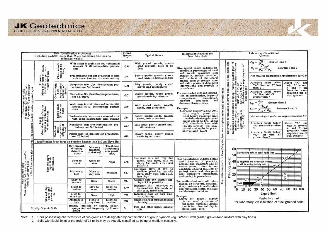
Note:
1 Soils possessing2 Soils with liquid
g characteristics of twolimits of the order of 3
UNIF
o groups are designat35 to 50 may be visual
FIED SOIL
ted by combinations olly classified as being
CLASSIFIC
of group symbols (eg. Gof medium plasticity.
CATION TA
GW-GC, well graded g
ABLE
gravel-sand mixture wwith clay fines).

JKG Log S
LOG
Groundw
Samples
Field Te
Moisture(Cohesiv (Cohesio
Strength(ConsistCohesiv
Density Relative(Cohesio
Hand PeReading
Remarks
GEOTEC
ymbols Rev1 Jun
G COLUMN
water Record
s
ests
e Condition ve Soils)
onless Soils)
h tency)
ve Soils
Index/ e Density onless Soils)
enetrometer gs
s
CHNICAL & ENV
e12
SYMBOL
ES U50 DB DS
ASB ASS SAL
N = 17 4, 7, 10
Nc = 5
7
3R
VNS = 25
PID = 100
MC>PL MC≈PL MC<PL
D M W
VS S F St
VSt H
( )
VL L
MD D
VD ( )
300 250
‘V’ bit
‘TC’ bit
60
VIRONMENTAL
C
4
Standing wa
Extent of bo
Groundwate
Soil sample Undisturbed Bulk disturbeSmall disturbSoil sample Soil sample Soil sample
Standard Peshow blows
Solid Cone Pfigures show ‘R’ refers to
R
Vane shear
Photoionisat
Moisture conMoisture conMoisture conDRY –MOIST –WET –
VERY SOFTSOFTFIRMSTIFFVERY STIFFHARDBracketed sy
Density IndVery LooseLooseMedium DenDenseVery DenseBracketed sy
Numbers indnoted otherwise.
Hardened st
Tungsten caPenetration rotation of au
ENGINEERS
LOG SYM
ater level. Time d
rehole collapse s
er seepage into b
taken over depth 50mm diametered sample takenbed bag sample taken over depthtaken over depthtaken over depth
enetration Test (Sper 150mm pen
Penetration Testw blows per 150mo apparent hamm
reading in kPa o
tion detector rea
ntent estimated tntent estimated tntent estimated t
– Runs freely t– Does not run– Free water vi
T – Unconfin – Unconfin – Unconfin – Unconfin
F – Unconfin -– Unconfin
ymbol indicates
ex (ID) Range (%<1515-35
nse 35-6565-85>85
ymbol indicates
dicate individual
teel ‘V’ shaped b
arbide wing bit. of auger string inugers.
MBOLS
D
delay following c
shortly after drilli
borehole or exca
h indicated, for er tube sample ta
n over depth indictaken over dept
h indicated, for ah indicated, for ah indicated, for s
SPT) performed etration. ‘R’ as n
t (SCPT) performmm penetration fmer refusal within
of Undrained She
ding in ppm (So
to be greater thato be approximatto be less than phrough fingers. freely but no freisible on soil surf
ned compressivened compressivened compressivened compressivened compressivened compressiveestimated consis
%)
estimated densit
test results in kP
bit.
n mm under stat
EFINITION
completion of dril
ng.
vation noted dur
environmental anken over depth incated. h indicated.
asbestos screeniacid sulfate soil asalinity analysis.
between depthsnoted below.
med between depfor 60 degree son the correspond
ear Strength.
il sample headsp
n plastic limit. tely equal to plas
plastic limit.
ee water visible oface.
e strength less the strength 25-50e strength 50-10e strength 100-2e strength 200-4e strength greatestency based on
SPT ‘N
ty based on ease
Pa on representa
ic load of rig app
lling may be sho
ring drilling or ex
nalysis. ndicated.
ing. analysis.
s indicated by lin
pths indicated byolid cone driven bing 150mm dept
pace test).
stic limit.
on soil surface.
han 25kPa 0kPa 00kPa 200kPa 400kPa er than 400kPa n tactile examina
N’ Value Range ( 0-4 4-10 10-30 30-50 >50
e of drilling or ot
ative undisturbed
plied by drill head
Pag
own.
xcavation.
es. Individual fig
y lines. Individuaby SPT hammer.th increment.
tion or other test
(Blows/300mm)
0 0
her tests.
d material unless
d hydraulics with
ge 1 of 2
gures
al .
ts.
)
s
hout

JKG Log Symbols Rev
ROCK M
Residual
Extremel
Distinctly
Slightly w
Fresh roc
ROCK SRock strenbedding. Abstract V
TE
Extremel
------------
Very Low
------------
Low:
------------
Medium
------------
High:
------------
Very Hig
------------
Extremel
ABBRE
ABBR
v1 June12
MATERIAL W
TERM
l Soil
ly weathered roc
y weathered rock
weathered rock
ck
STRENGTH ngth is defined bThe test proc
Volume 22, No 2,
ERM SY
ly Low:
------------
w:
------------
------------
Strength:
------------
------------
h:
------------
ly High:
----
----
----
----
-----
-----
EVIATIONS U
REVIATION
Be CS J P
Un S R IS
XWS Cr 60t
WEATHERIN
SYMBO
RS
ck XW
k DW
SW
FR
by the Point Loacedure is desc 1985.
YMBOL Is (5
EL
-----------
VL
-----------
L
-----------
M
-----------
H
-----------
VH
-----------
EH
USED IN DE
DES
Bedding Plane Clay Seam Joint Planar Undulating Smooth Rough Ironstained Extremely WeaCrushed Seam Thickness of de
LO
NG CLASSIF
OL
Soil develoevident; th
Rock is weremoulded
Rock strenironstainingweathering
Rock is slig
Rock show
d Strength Indexribed by the
50) MPa
0.03
0.1
0.3
1
3
10
Eas May A pieknife
A piewith A piescra
A pieone
A pieRing
EFECT DESC
SCRIPTION
Parting
thered Seam
efect in millimetre
OG SYMBOL
FICATION
oped on extremelyhere is a large cha
eathered to such , in water.
ngth usually chang. Porosity mayg products in pore
ghtly discoloured
ws no sign of deco
x (Is 50) and refInternational Jo
ily remoulded by
y be crumbled in t
ece of core 150me. Sharp edges o
ece of core 150m knife.
ece of core 150matched or scored w
ece of core 150mblow. Cannot be
ece of core 150mgs when struck wi
CRIPTION
es
Defec(ie re
LS continue
D
y weathered rockange in volume bu
an extent that it
nged by weathery be increased bes.
but shows little or
omposition or stain
fers to the strengournal of Rock
hand to a materia
he hand. Sandst
mm long x 50mm dof core may be fria
mm long x 50mm d
mm long x 50mm dwith knife; rock ri
mm long x 50mm de scratched with p
mm long x 50mm dith a hammer.
ct orientations melative to horizont
d
DEFINITION
k; the mass strucut the soil has not
has “soil” proper
ring. The rock y leaching, or m
r no change of str
ning.
gth of the rock sk Mechanics, M
FIELD GUIDE
al with soil propert
one is “sugary” an
dia. may be brokeable and break du
dia. can be broken
dia. core cannot bngs under hamme
dia. may be brokeen knife; rock rin
dia. is very difficul
NOT
measured relativetal for vertical ho
cture and substant been significantl
rties, ie it either d
may be highly dmay be decreased
rength from fresh
substance in theMining, Science
E
ties.
nd friable.
en by hand and eauring handling.
n by hand with dif
be broken by hander.
en with hand-held ngs under hamme
lt to break with ha
TES
e to the normal oles)
Page
nce fabric are no y transported.
disintegrates or c
discoloured, usuad due to deposit
rock.
direction normae and Geomec
asily scored with a
fficulty. Readily s
d, can be slightly
pick after more ther.
and-held hammer.
to the long core
2 of 2
longer
can be
ally by tion of
al to the chanics.
a
cored
han
.
e axis