Embed Size (px)
Citation preview
7AD-R126 274 FY (FISCAL YEAR) 1982 ANNUAL LABORATORY POSTURE REPORT t/t(U) ARMY TANK-AUTOMOTIVE COMMAND WARREN MI 1982
UNCLASSIFIED F/G 5/1 NLI'L-_/BE|||E|IEhlhlllllllllIElllllIlllillImhhmhhhhlmhhhIIIBIIIEIh~Iwji
.4
'°l77
: Il,'
1.0 __&5 Q3
1.25 U-114 jjL
MICROCOPY RESOLUTION TEST CHART
NATIONAL BUREAU OF STANDARDS-1963-A
4'
,. " I
a • °." -. . .. . . .. . . . .
command executive staff
i
BG C.M. Matthews, Jr.Commanding General
i ,~--
Cal Jerry K. Patterson Cpt William Weir Dr. Ernest N. Patrick
Deputy Commander Executive Officer Technical Director
I&T I
S! A lc1"OS'
command executive staff
Edward Jackovich Col T.H. HuberDirector, Tank-Automotive Director, Tank-Automotive
Systems Laboratory Concepts Laboratory(Acting)
LTC Morton Brisker Coi N.H. Dobbs George NiewcombProject Officer Chief, Systems & Director, EngineeringVehicle NBC Technoiogy Planning Office Support Directorate
4T
4Col J.V. Wasson Robert E. SimakChief, Tank Development Chief, Foreign
Office Intelligence Office
TABLE OF CONTEMN
t."
Executive Staff, ~.... . . . . . . . .. . . . . . . . . 1Mngmn- ... .. .. .. .. .. .. .. .. .. .. .. ..I
("-Technical Achievements' . . . . . . . . . . 15iNoteworthy Technical Management Actions,- . . . . . . . . . . . . 20
-, Major Personnel and Manpower Situation' ............. 21/)
J4ajor Management Improvements . . . . . . . . . . . . . . . . . 22
Planning - Fisca l Program. ........ ......... 26
-qnside/Outside Expenditures,,*.. ................. . . . . . . 28
-'Outstanding Accomplishments by In-House Personnel) . . . . . . . 29
Program Balance Sheet . . . . . . . . . . . . . ........ 32
Technical Achievements by Program Breakout;. ... ........... .33
Activity Indicators'. . . . . ............... 61
Facilities . ............ ...... 62
tw!, .o,
ORGANIZATION AUSOSGNUMnW3PONSLrM
LAUK-ATORY The Combat Systems Division conducts
advanced development and engineering
The Tank-Automotive Concepts Laboratory development for combat vehicles through first
(TACL) was established to focus mangement production and initial fielding. This division
attention on advanced vehicle development provides technical support, world-wide, to
- program, initiatives, and survivability. TACL planners, producers and users of combat
* operated during FY82 with an organization vehicles, including product improvement
structure consisting of an* Exploratory programs. In the area of vehicle subsystems
Development Division, a Survivability and components, the Combat Systems Division
Research Division, and a Program Control directs research on potential track materials,
Office. and executes exploratory and advanceddevelopment of armor, track and suqpnrsion,
The Exploratory Development Division is combustion fire detection and suppression, and
responsible for advanced military vehicle composite materials for combat vehicle
system research, concept feasibility studies, applications. Also, it executes an integration
and advanced engineering design programs, role for both fire control and fire survivability
including the development and maintenance of programs for ground combat vehicles. It also
tank-automotive long-range technology/ directs and coordinates the manufacturing
methodology programs. methods and technology, and Military AdaptedCommercial Item Programs for ground
The Survivability Research Division is vehicles. The Weapons System Managers for
responsible for basic and applied research the Field Artillery Ammunition Supply Vehicle
*_ directed toward new and :,%,-oved vehicle and the Small Unit Support are assigned here.
performance, operational capability, During FY81, organizational changes weresurvivability including research leading to newprinciples for sensing and measuring vehicle implemented to form a Tactical Wheeled
signatures and electromagnetic interference, Vehicle Systems Division which is the parent
counter-surveillance, signature reduction, organization of two subdivisions. The sudden
electronic warfare countermeasures for increase in tactical wheeled vehicle workload,
S- military vehicle systems, and for exploratory and accelerated schdules on the M939 5-ton,
development programs in ground mobility. CUCV, HMMWV and 10-Ton M.A.N. truckprograms resulted in the establishment, on 1
July 81, of the Tactical Wheeled VehicleDivision. It is structured to provide intensive
management of the aforementioned truck
programs, as well as mission responsibilitiesand resources of the Tactical Wheeled Vehicle
Management Office. This office providesimproved control and cost effective
0 TAMK-AUTOUOIWK s=m management of the Army's tactical fleet
"LABORATORY throughtout the life cycle. This division is
responsible for vehicle development,
The Tank-Automotive Systems Laboratory engineering development, and production
(TASL) was organized to consolidate research, engineering and management of performance-
development, engineering efforts, and conduct related product-improvement programs for
of performance-related product-improvement tactical wheeled vehicles.
programs and consists of three divisions
(Combat Systems, Tactical Wheeled Vehicle The Tactical Systems Support Division
Systems-with two divisions, and Propulsion manages advanced military tactical wheeled
Systems) and one supporting office (Program vehicle systems, engineering design and
Control). 4 development programs, including improved
' o - B, " h • u • - " '- -, - -.. . . - '*. . - , . - • •.4 ° ° '
MANAGEMENT
SORGANIZATION ASMIGNW2R/U1PNOMMII
LTmethods of assessing the effectiveness of SYSTEM & TECHNOLOGY PLANNING OFFICEfuture transport, and tactical and special (STPO)vehicle designs. It is involved in managing thetactical vehicle systems design, development In FY82, the STPO continued as the R&Dand engineering programs through first Center's mid-and-long range planning ele-production and initial fielding of a number of ment. This office establishes future
t tactical support wheeled vehicles (e.g., Semi- technological development goals through atrailers for GLCM, PATRIOT and MLRS) by variety of means. These include the
* providing the necessary technical direction DA-wide Armored Combat Vehicle Scienceand resources essential to the accomplishment and Technology Base Development Program;of the maintenance, supply, procurement, systems planning activities in conjunc-production and the industrial mobilization tion with TRADOC; international datarequirements for support vehicles. In addition, exchange agreements with NATO and ourit is responsible for planning, directing and other allies; and extensive interchange
- conducting research, development and of information with industry throughengineering of components such as materials, independent research and development andwheels, mechanical and electrical devices, other initiatives.tires, special automotive kits and
. environmental systems for tactical, During the year, the office also becameautomotive vehicles, the Command's link with the High
Technology Light Division activity at Ft.Propulsion Systems Division responsibilities Lewis, Washington. This involved a majorinclude research, development, qualification, redirection of assets to address properlyand integration of combat and tactical vehicle this highly visible activity and to pro-engines, transmissions, air cleaners, cooling vide it with the intensive management
. systems, diagnostic and prognostic equipment, required to respond to rapidly evolvingand electrical power distribution and short term requirements. This commitmentmanagement systems. Due to the increasing is expected to expand in the coming yearapplication of electronics in military ground as requirements are solidified.vehicles and resulting electrical systemsophistication, an added responsibility hasbeen included called VETRONICS. This
-program will account for the integration of allelectrical/electronic/sensing systems intomilitary vehicles. It also performs thecompilation and exchange of data with foreignand U.S.-based industries for the aboveactivities.
Program Control Office provides budget andprogram support services to the SystemsLaboratory, and administers the TACOM costreduction, military adaptation of commercialitems, and manufacturing methods andtechnology program accounts.
An ancillary office, the ComputerManagement and Application Research Office,consolidates TACOM's computer assets forcontrol and function priorities.
5
ORGANiAIOMN ASMSIMMM"NmIRmon m
vzEUMc NBC PuO'rCTN TACTICAL WHEELED VEHICLE DIVISION
The Development Project Office for The Tactical Wheeled Vehicle Division is
Vehicle NBC Protection was chartered in responsible for vehicle development,1979 by DARCOM Regulation 1-10 to plan, engineering development and production
intensively manage, and direct the expe- engineering and management of performance
dited development of Hybrid Collective related product improvement programs for
Protection Equipment (HCPE) for selected selected tactical wheeled vehicles. The
combat vehicles. Division provides itensive management tothe M939-Series 5-ton truck program, CUCV,
During Fiscal Year 1982, DARCOM tasked HMMWV, F.A.V., and 10 ton M.A.N. truck
TACOM to insure that programs for programs. The Division has a systemNBC/cooling are part of a unified plan. manager for each vehicle program who is
This assignment established a single responsible for overall management of
manager responsbiliity for armored that particular program. The mission
vehicle NBC/cooling efforts. The respon- responsibilities of the Tactical Wheeled
sibility covers all aspects of Vehicle Management Office are also con-
NBC/cooling, including oversight and tamed within this Division.guidance on component development andsoldier interface as well as the standardTACOM mission of systems integration. TACTICAL WHEELED VEHICLE MANAGEMENTAdditionally, a TACOM R&D Center charter OFFICEestablished a Technical Area Manage (TAM)for Life Support. Life support is The Tactical Wheeled Vehicle Managementdefined as that area of human factors Office's (TWVMO) mission is to developwhich applies scientific knowledge to and maintain overall fleet acquisition,items which require special attention to product improvement, maintenance andor provisions for personnel health, replacement planning to provide asafety, protection, sustenance, escape, balanced, economical and effective tac-survival and recovery. This Life Support tical vehicle fleet. TWVMO also coor-TAM is to provide overall direction and dinates interchange requirements from
- coordination of all life support matters other commands and develops interdepart-related to TACOM vehicles, present and ment requests from other services. TWVMOfre. th TAM i uer respnt sil is involved in coordinating the procure-.future. The TAM is further responsible e t p a n g fo th bu et r c s .for coordinating life support plans and ment planning for the budget process.actiitis wthinthedevlopmnt om- Program planning also is on-going for aactivities within the development com- ne hi l b t en he 1 - on o 5 t n: muityand t hgherArm levlsnew vehicle between the 1 - ton to 5-tonmunity and at higher Army levels, class: The Medium Tactical Truck (MTT),
This Development Project Office also which will replace the 2-4 ton truck.
* monitors the resolution of crew perfor- TWVMO is also responsible for Tactical
mance degradation imposed by NBC protec- Wheeled Vehicle Studies.
tion measures.
0
*
MANAGEMENT
ORGANIZATION A0SIGN1MENT PON]BUEIhIES
TANK DEVELOPMENT OFFICE FIELD ARTILLERY AMMUNITION SUPPORTVEHICLE (FAASV) WEAPON SYSTEM MANAGER'S
The Tank Development Office focuses mana- (WSM) OFFICEgement attention on requirements issuesaffecting the combat vehicle technology The FAASV Weapon System Manager Charterbase. It assists the Commander, TACOM R&D was renewed on 26 April 82. The firstCenter, in meeting user needs relating to two Full Scale Engineering Developmentthe design or development of new or (FSED) prototype vehicles were designed,improved ground combat systems. fabricated and delivered by November
1982. The FAASV prototype vehicles suc-During FY82, the Tank Development Office cessfully completed the Prototypewas involved with the Future Close Combat Qualification Test-Government andVehicle Concept Study; Combat Vehicle Operational Test II in April 1982.Science and Technology Base Program; Test The production contract ProcurementBeds; Armored Support Vehicles; Request (PR) package was forwarded to theCounter-Obstacle and Counter-Mine Vehicle Procurement and Production Directorate,Systems; Military Motorcycle and Helmet; TACOM, during September 1982. The
and Ammunition Packaging and Battlefield Request for Proposal (RFP) is scheduledHandling Concepts. Also, the office was for release during October 1982 withprominent in management issues relating contract award scheduled for March 1983.to the development and production oftrack components, power trains, life sup- Funding resources are adquate and thereport and survivability sub-systems, high are no known shortfalls or problems thatvisibility hatches, system product impro- will jeopardize the scheduled Novembervements and system integration. 1984 FAASV Program IOC date.
47
-2'
N OTEWORTHY TECHNICAL COnTumTIONS
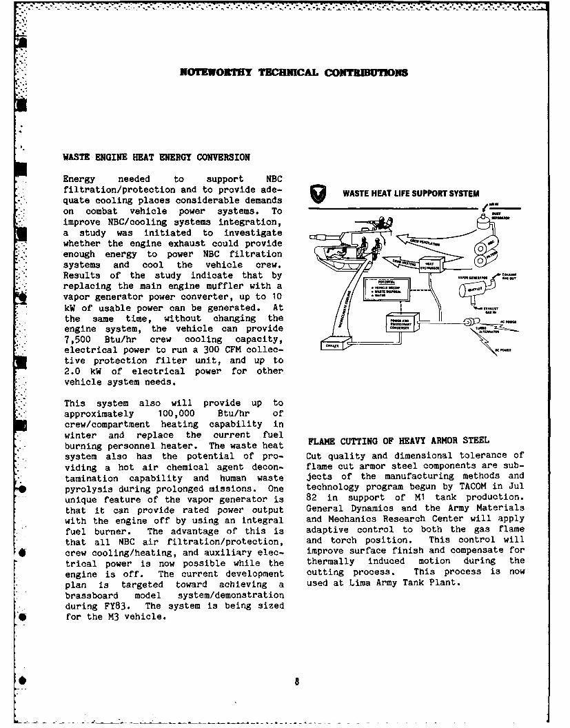
WASTE ENGINE HEAT ENERGY CONVERSION
Energy needed to support NBCfiltration/protection and to provide ade- WASTE HEAT LIFESUPPORTSYSTEM
,-, quate cooling places considerable demandson combat vehicle power systems. Toimprove NBC/cooling systems integration,a study was initiated to investigatewhether the engine exhaust could provideenough energy to power NBC filtrationsystems and cool the vehicle crew. HUT
Results of the study indicate that by - -'h.M"TOreplacing the main engine muffler with avapor generator power converter, up to 10 L . 7kW of usable power can be generated. At C-.,
the same time, without changing the Pam / --engine system, the vehicle can provide A nsM7,500 Btu/hr crew cooling capacity,electrical power to run a 300 CFM collec-tive protection filter unit, and up to2.0 kW of electrical power for othervehicle system needs.
This system also will provide up toapproximately 100,000 Btu/hr ofcrew/compartment heating capability in
* winter and replace the current fuelburning personnel heater. The waste heat FLAME CUTTING OF HEAVY ARMOR STEEL
* system also has the potential of pro- Cut quality and dimensional tolerance of
viding a hot air chemical agent decon- flame cut armor steel components are sub-
tamination capability and human waste jects of the manufacturing methods and
pyrolysis during prolonged missions. One technology program begun by TACOM in Jul
unique feature of the vapor generator is 82 in support of M1 tank production.
that it can provide rated power output General Dynamics and the Army Materials
with the engine off by using an integral and Mechanics Research Center will apply
fuel burner. The advantage of this is adaptive control to both the gas flame
that all NBC air filtration/protection, and torch position. This control will
crew cooling/heating, and auxiliary elec- improve surface finish and compensate for
trical power is now possible while the thermally induced motion during the
engine is off. The current development cutting process. This process is now
plan is targeted toward achieving a used at Lima Army Tank Plant.
brassboard model system/demonstrationduring FY83. The system is being sized
• for the M3 vehicle.
NOTEWORTHY T"EI CHAL CONTRIBUTIONS
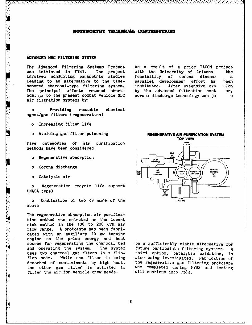
ADVANceD NBC FILTERING SYSTEM
The Advanced Filtering Systems Project As a result of a prior TACOM projectwas initiated in FY81. The project with the University of Arizona theinvolved conducting parametric studies feasibility of corona dischar aleading to an alternative to the time- parallel development effort ha, Ibeenhonored charcoal-type filtering system. instituted. After extensive eva ionThe principal efforts reduced short- by the advanced filtration cont or,comings to the present combat vehicle NBC corona discharge technology was ju 0air filtration systems by:
o Providing reusable chemical
agent/gas filters (regeneration)
o Increasing filter life
o Avoiding gas filter poisoning REGENERATIVE AIR PURIFICATION SYSTEMTOP VIEW
Five categories of air purification ACTUATOR
methods have been considered:
o Regenerative absorption WA__T
o Corona discharge
o Catalytic air
o Regeneration recycle life support(NASA type)
VALVEo Combination of two or more of the .....
*. above
The regenerative absorption air purifica-
tion method was selected as the lowestrisk method in the 100 to 200 CFM airflow range. A prototype has been fabri-cated with an auxiliary 10 kw turbine
- engine as the prime energy and heat" source for regenerating the charcoal bed be a sufficiently viable alternative for4 and operating the system. The system future particulate filtering systems. A
uses two charcoal gas flters in a flip- third option, catalytic oxidation, isflop mode. While one filter is being also being investigated. Fabrication ofdesorbed of contaminants by high heat, the regenerative gas filtering prototypethe other gas filter is utilized to was completed during FY82 and testingfilter the air for vehicle crew needs. will continue into FY83.I
4 9
NOTEWORTHY TECHNICAL CONTRIBUTIONS
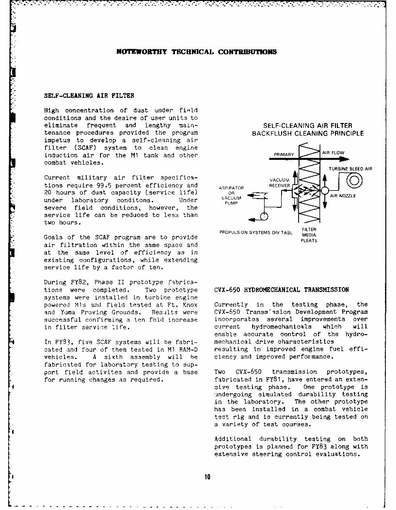
SELF-CLEANING AIR FILTER
High concentration of dust under fieldconditions and the desire of user units toeliminate frequent and lengthy main- SELF-CLEANING AIR FILTERtenance procedures provided the program BACKFLUSH CLEANING PRINCIPLEimpetus to develop a self-cleaning airfilter (SCAF) system to clean engineinduction air for the M1 tank and other PRIMARY AIR FLOW
combat vehicles. -0-
TURBINE BLEED AIR
Current military air filter specifica- VACUUM C 0tions require 99.5 percent efficiency and ASPIRATOR RECEIVER.., 20 hours of dust capacity (service life) OR AIRNOZL
under laboratory conditons. Under VACUUMPUMP
severe field conditions, however, theservice life can be reduced to less than
two hours.FILTERPROPULSION SYSTEMS DIV-TASL MEIAE
Goals of the SCAF program are to provide LMEDIAPLEATS
air filtration within the same space andat the same level of efficiency as inexisting configurations, while extendingservice life by a factor of ten.
During FY82, Phase II prototype fabrica-tions were completed. Two prototype CVX-650 HYDROMECHANICAL TRANSMISSIONsystems were installed in turbine enginepowered Mls and field tested at Ft. Knox Currently in the testing phase, theand Yuma Proving Grounds. Results were CVX-650 Transm>3sion Development Programsuccessful confirming a ten fold increase incorporates several improvements overin filter service life. current hydromechanicals which will
enable accurate control of the hydro-In FY83, five SCAF systems will be fabri- mechanical drive characteristicscated and four of them tested in M1 RAM-D resulting in improved engine fuel effi-vehicles. A sixth assembly will be ciency and improved performance.fabricated for laboratory testing to sup-port field activites and provide a base Two CVX-650 transmission prototypes,for running changes as required. fabricated in FY81, have entered an exten-
sive testing phase. One prototype isundergoing simulated durability testingin the laboratory. The other prototypehas been installed in a combat vehicletest rig and is currently being tested ona variety of test courses.
Additional durability testing on bothprototypes is planned for FY83 along withextensive steering control evaluations.
10
NOTEWORTHY TECHNICAL CONTRIBUTIIONS
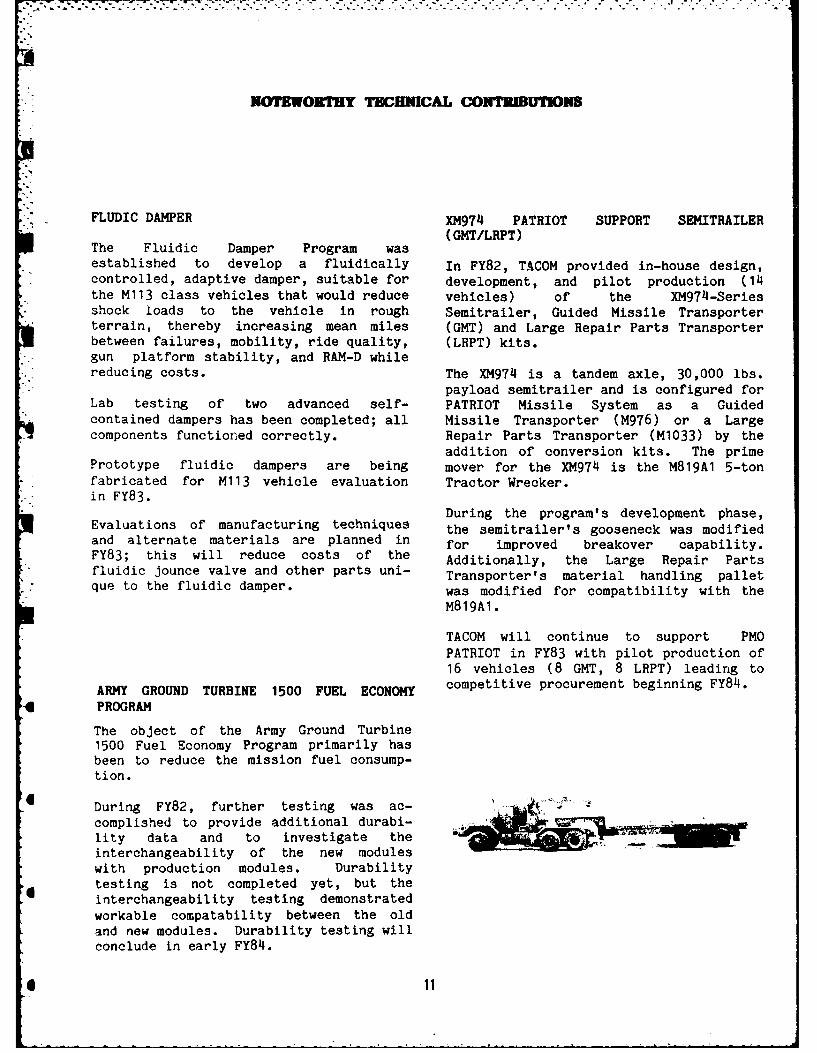
FLUDIC DAMPER XM974 PATRIOT SUPPORT SEMITRAILER(GMT/LRPT)
The Fluidic Damper Program wasestablished to develop a fluidically In FY82, TACOM provided in-house design,controlled, adaptive damper, suitable for development, and pilot production (14the M113 class vehicles that would reduce vehicles) of the XM974-Seriesshock loads to the vehicle in rough Semitrailer, Guided Missile Transporterterrain, thereby increasing mean miles (GMT) and Large Repair Parts Transporterbetween failures, mobility, ride quality, (LRPT) kits.gun platform stability, and RAM-D while
* reducing costs. The XM974 is a tandem axle, 30,000 lbs.payload semitrailer and is configured for
Lab testing of two advanced self- PATRIOT Missile System as a Guided" contained dampers has been completed; all Missile Transporter (M976) or a Large
components functioned correctly. Repair Parts Transporter (M1033) by the
addition of conversion kits. The primePrototype fluidic dampers are being mover for the XM974 is the M819A1 5-tonfabricated for M113 vehicle evaluation Tractor Wrecker.in FY83.
i oDuring the program's development phase,Evaluations of manufacturing techniques the semitrailer's gooseneck was modifiedand alternate materials are planned in for improved breakover capability.FY83; this will reduce costs of the Additionally, the Large Repair Partsfluidic jounce valve and other parts uni- Transporter's material handling palletque to the fluidic damper. was modified for compatibility with the
M819A1.
TACOM will continue to support PMOPATRIOT in FY83 with pilot production of16 vehicles (8 GMT, 8 LRPT) leading to
ARMY GROUND TURBINE 1500 FUEL ECONOMY competitive procurement beginning FY84.
-4 PROGRAM
The object of the Army Ground Turbine1500 Fuel Economy Program primarily hasbeen to reduce the mission fuel consump-tion.
6 During FY82, further testing was ac-complished to provide additional durabi-lity data and to investigate theinterchangeability of the new moduleswith production modules. Durabilitytesting is not completed yet, but the
6 interchangeability testing demonstratedworkable compatability between the oldand new modules. Durability testing willconclude in early FY84.
* 11
Z I
YWNOT WORHY TECHICAL CONTRDUIMNS
- FIELD ARTILLERY AMMUNITION SUPPORT VEHICLE INTEGRATED DEFENSE SYSTEM (VIDS)-* VEHICLE (FAASV) XM922
The Tank-Automotive Concepts LaboratoryThe contract for design, fabrication and is developing a combat vehicle self-
delivery of five prototype XM992 FAASVs protection system to increase battlefi.: Idwas awarded on 25 March 1981 to BMY survivability for futre ground-bornf,
Division of Harsco Corp, York, PA. combat vehicles. This vehicle integratediThe first two Full-Scale Engineering defense system (VIDS) incorporates aDevelopment prototype vehicles were suite of threat detection devices, coun-designed, fabricated and delivered to termeasure responses or reactions,Yuma Proving Grounds, AZ, for Prototype display and communications interantioci,Qualification Test-Government testing and threat warning hardware from whichwhich was completed in April 1982. the best combination may be selected and
used.The three remaining FAASV vehicles were
delivered during December 1981 to the US The technology basis for this integrated
Army Field Artillery Board, Ft. Sill, self-protection system is aOK, for Operational Test II (OTII). The microprocessor-based processor, iden-FAASV OTII tests were also completed tified as the Data Management Systemdi-ing April 1982. (DMS). The DMS is structured to interro-
gate sensor engagement algorithms bazed-on threat information from a suite of
ifearly warning sensors. Threat classifi-cation and prioritization areaccomplished based upon diScriminat ionanalysis of identified threat parametersand multi-disciplined threat charac-terization.Optimum countermeasure reactions ileither be automatically activated by the
" Data Management System, or implemented by0- the vehicle commander, based on artifi-
cial intelligence displayed or otherwise*t communicated to him.
oVIUb-UMb FhASIBILITY DEMONSTRATION MUI:L
45- 65-TON VEHICLE TRACK
Testing of a fabricated, lightweight, GRW.
replaceable pad track for the M1 tank ,__ .track commenced in FY82. Based upon thepositive test results, Phase II testing -IF -RI
of an improved version of this track will.. o....- "f
be conducted in FY83. . COMPUTER
In addition, the application of new CNOL 6W.. OICE
materials, such as laminated metals and a A A
m e t a l m a t r i x t o t a n k t r a c k , w i l l b e D S U E o t N R A, .investigated.
[k %
i 12
NOTWORTE Y TIECH1CAL COI TIINS
Significant program achievements include A typical combat vehicle has as many as
successful field demonstrations of threat 100 incandescent lamps, which are illumi-
warning systems for helicopter threats, a nated during night operations. Through an
limited Data Management System and ongoing secure lighting program, each lamp
several countermeasure responses. A will be examined and redesigned to emit
system specification has been completed only energy visible to the human eye and
for a developmental DMS incorporating to optimize its intensity using light-
military computer hardware and ADA higher emitting diodes.
order language. Hardware and softwarefabrication of the developmental DMS is Various concepts for meeting vehicular
in progress. Radiological and chemical lighting needs have been found and
warning devices have been integrated with modification kits are being designed for
the DMS to provide protection against combat vehicle blackout lighting systems.
additional battlefield threats. Crew Modifications of all combat and tactical
interface is being optimized through vehicles are scheduled ,o begin in thevoice synthesis and visual display sym- 1986-90 time frame. The effort is to bebology. accomplished through Product Improvement
Proposals (PIP).
SECURE LIGHTING PROGRAM ADVANCED COUNTERMEASURES
TACOM's investigation into detection Vehicle "Signatures" are important vulnerabiat night by threat forces using low-light lity descriptors used as inputs to sensorlevel (LLL) imaging devices revealed that directed anti-tank weaponery. Signaturcurrent blackout security lighting is measurements are routinely made in thineffective. The near-infrared portion infrared/thermal, visible and millimeter wavof incandescent lamp emission "leaking" electromagnetic regions as well as in thfrom openings in the hull and turret made acoustic spectrum. Reducing or modifyingthe vehicle easily visible at ranges vehicle's signature is a primary objective o
* exceeding 2 km with LLL imaging devices, the Advanced Countermeasures program.By restricting emission of a lamp toenergy only in the visible portion of the Reduction in quantitative signature levelEM spectrum, the signature of that lamp correspond to reduced detection and idento a typical LLL device could be reduced tification ranges for sensory directed anti
4 by 28 dB with no loss of visibility tank weapons.inside the vehicle.
Signature Control is now an integral part oTACOM and TRADOC compared the signature the overall vehicle survivability programof a blue-green infrared absorbing filter No longer is it feasible to keep adding armoover a blackout dome lamp to that of a to a vehicle in response to new anti-tanred filtered dome light. The red weaponery. Survivability now depends on noblackout light was clearly visible being detected and when detected, not beithrough LLL sensors while the blue-green identified. Signature Control addresselight virtually disappeared. these considerations.
*13
muvrworHy TECHNCAL COMWIOMS
Significant achievements have been made inreducing the thermal/ infrared signature ofcombat vehicles through the use of thermalsuppression hardware. Of specific interestare turbine powered vehicles which requirespecial treatment of the hot exhaust gases toreduce their signatures.
Comparable achievements have been made inAcoustics, Millimeter Wave and VisualSignature Control. Future vehicles such asthe Mobile Protected Gun and Close CombatVehicle will incorporate signature reductionin their design as well as dedicated systemsayid material to reduce signature generation.
41
* 14
.. ,Tl C ALll im
MANA EIMT OF REOURCM
M?&T/MACI PROGRAM MOVING TARGET INDICATION (MTI)," DEVELOPMENT
Major studies were undertaken in FY82 inthe growth and development of the TACOM A real-time analysis of vehicle infraredMMT/MACI Program. Thrust areas included imagery is becoming more important forthe M1 tank, the AGT-1500 Turbine Engine, vehicle battlefield survivability. Thethe M2/M3 Fighting Vehicle Systems, MBT Moving Target Indicator (MTI) passivelyTrack and Suspension, Advanced Special detects the presence of vehicle motion byArmor Systems, Depot Modernization, and using an image data reduction algorithm.Tactical Vehicles. Targeted objectives The MTI supp'ies the tank commander withinclude return on investment of 6.1; vital information such as the speed andimproved manufacturing productivity and direction of the target.quality; lighter vehicles; longer vehiclelife; improved vehicle operating SCANNING PHOTOACOUSTIC MICROSCOPYefficiency; updated manufacturingfacilities; updated depot facilities; a Scanning photoacoustic microscopy (SPAM)
* strengthened mobilization base; and a is a nondestructive evaluation techniquestrong manufacturing engineering team. applicable to the Adiabatic DieselThe paths to these objectives include the engine, to high performance gas turbineapplication of new manufacturing tech- engines, and to track shoe pads. Sincenologies, the use of new materials, the SPAM is dependent of thermal propertiesadoption of commercial items, and the as well as optical absorption, it produ-application of Industrial Productivity ces information that is different fromImprovement (IPI) Programs. TACOM budget optical images alone. The SPAM infor-figures for FY82 were slightly under $20 mation may be produced as graphicalmillion while the FY83 budget will exceed displays, color video images and sta-
- $32 million. However, a shortfall is tistical measures. Color video can beapparent in FY84. Individual program used for a pseudocolor presentation of
, progress and implementation are reported SPAM data and is necessary if both theelsewhere in this report. phase ani magnitude at a single point is
to be p,.esented simultaneously. Colorvideo images have been produced combiningthe two in-phase and quadrature pho-toacoustic signals on a single pseudoco-
'IN-HOUSE LABORATORY INDEPENDENT RESEARCH br graphic display.
(ILIR)
During FY82, the Tank-Automotive ConceptsLaboratory conducted research in several INVERSE DESIGN MODELING OF FLUID FLOWscientific fields including optics, PASSAGES WITH TEMPERATURE GRADIENTSultrasonics, radar, control theory,infrared, material properties, heat The inverse design technique providestransfer and thermodynamics. Researchers TACOM with a rapid design/analysis capa-it, this program contributed a number of bility for ducts, nozzles, and other flowpublications and presentations at scien- passages within military gas turbinetific and engineering symposia. In addi- engines. This inverse design proceduretion, several researchers are combining has been applied to subsonic, sonic, andtheir ILIR program with their Master and transonic compressible flow cases withoutDoctoral dissertation requirements. singularities appearing in the final
tt 15
i-]" TEIBC AL ACUrlKVIU1
solutions. A single streamline is spe- Elevation and azimuth controllers arecified by a frame independent streamtube being formulated to investigate weaponformulation, and the spatial position of stabilization under various operatingthe calculated adjacient streamlines is conditions. Articulated tracked andplotted graphically as a computer output, wheeled vehicle models (incorporating
servo control systems) and soil-interface
6.- BMW RM CH models are being developed to predictvehicle performance and to investigate
The Tank-Automotive Concepts Laboratory's controlled articulation enhancement of
work under "Research in Vehicle Mobility" vehicle mobility. These vehicle models
is divided into four areas: have significantly enhanced TACOM'scurrent vehicle design and evaluation
0 Applied Mobility Research process and they form the basis forTACOM's full scale dynamic simulation
0 Countermeasures Research research tasks.
0 Dynamics and Control Research
0 Materials and Components Technology
The Structural Image Analysis Programwhich began in FY81 continued into FY82.A stand-alone digital image processingsystem was acquired to analyze infraredand photometric images of U.S. and threatcombat and tactical vehicles. A percep-tability analysis was performed on i- -__-
several representative U.S. and threat - -
vehicle images by digitizing them anddetermining subsequent noise thresholdlevels for trained Army observers. The -
final results were tabulated and comparedwith the theoretical guidelines for thistype of signal-to-noise analysis.
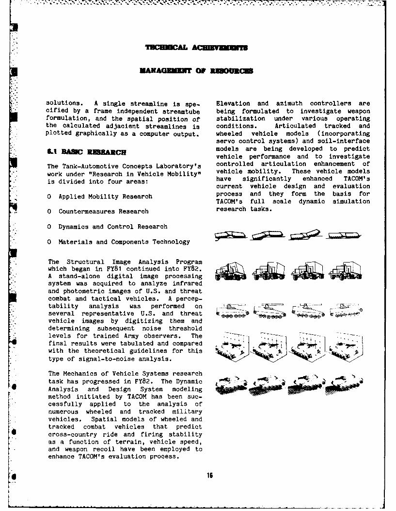
The Mechanics of Vehicle Systems research Ntask has progressed in FY82. The Dynamic ja aAnalysis and Design System modelingmethod initiated by TACOM has been sue-cessfully applied to the analysis ofnumerous wheeled and tracked militaryvehicles. Spatial models of wheeled andtracked combat vehicles that predictcross-country ride and firing stabilityas a function of terrain, vehicle speed,and weapon recoil have been employed toenhance TACOM's evaluation process.
16
.-7--- . 77- 77.
3 MANAGEMENT OF RESOURCES
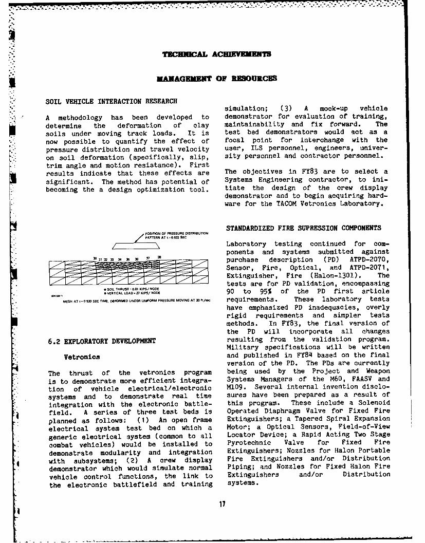
SOIL VEHICLE INTERACTION RESEARCHsimulation; (3) A mock-up vehicle
A methodology has been developed to demonstrator for evaluation of training,determine the deformation of clay maintainability and fix forward. Thesoils under moving track loads. It is test bed demonstrators would act as a
now possible to quantify the effect of focal point for interchange with the
pressure distribution and travel velocity user, ILS personnel, engineers, univer-
on soil deformation (specifically, slip, sity personnel and contractor personnel.trim angle and motion resistance). Firstresults indicate that these effects are The objectives in FY83 are to select a
significant. The method has potential of Systems Engineering contractor, to ini-
becoming the a design optimization tool. tiate the design of the crew displaydemonstrator and to begin acquiring hard-ware for the TACOM Vetronics Laboratory.
STANDARDIZED FIRE SUPRESSION COMPONENTSPOSITION OF PRESSURE DISTRIBUTIONPATTERN AT I=0.5M SEC
Laboratory testing continued for com-ponents and systems submitted against
30 31- 32 33 3 35 3 37 - , purchase description (PD) ATPD-2070,
Sensor, Fire, Optical, and ATPD-2071,Extinguisher, Fire (Halon-1301). Thetests are for PD validation, encompassing
* SOIL THRUST= 0.1 KIPS/ NODEVERTICALLOAD ,27KPS/NODE 90 to 95% of the PD first article
" MESH AT t 0.5M SEC TIME. DEFORMED UNDER UNIFORM PRESSURE MOVING AT 3/ ft requirements. These laboratory testshave emphasized PD inadequacies, overlyrigid requirements and simpler testsmethods. In FY83, the final version ofthe PD will incorporate all changes
6.2 EXPLORATORY DEVELOPMENT resulting from the validation program.Military specifications will be written
Vetronics and published in FY84 based on the finalversion of the PD. The PDs are currently
The thrust of the vetronics program being used by the Project and Weapon
is to demonstrate more efficient integra- Systems Managers of the M60, FAASV and
tion of vehicle electrical/electronic M109. Several internal invention disclo-
systems and to demonstrate real time sures have been prepared as a result of
integration with the electronic battle- this program. These include a Solenoid
field. A series of three test beds is Operated Diaphragm Valve for Fixed Fire
planned as follows: (1) An open frame Extinguishers; a Tapered Spiral Expansion
electrical system test bed on which a Motor; a Optical Sensors, Field-of-View
generic electrical system (common to all Locator Device; a Rapid Acting Two Stage
combat vehicles) would be installed to Pyrotechnic Valve for Fixed Fire
demonstrate modularity and integration Extinguishers; Nozzles for Halon Portable
with subsystems; (2) A crew display Fire Extinguishers and/or Distributiondemonstrator which would simulate normal Piping; and Nozzles for Fixed Halon Fire
vehicle control functions, the link to Extinguishers and/or Distribution
the electronic battlefield and training systems.
17
TECHNICAL ACHIEVEMM NI
MANAGEMENT OF RESOURCU
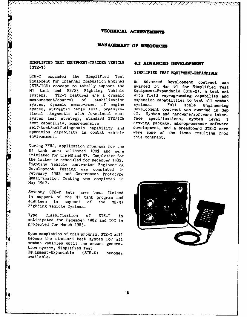
SIMPLIFIED TEST EQUIPMENT-TRACKED VEHICLE 6.3 ADVANCED DEVELOUMET( STE-T )SIMPLIFIED TEST EQUIPMENT-EXPANDIBLE
STE-T expanded the Simplified TestEquipment for Internal Combustion Engines An Advanced Development contract was(STE/ICE) concept to totally support the awarded in Mar 81 for Simplified TestM1 tank and M2/M3 Fighting Vehicle Equipment-Expandable (STE-X), a test setsystems. STE-T features are a dynamic with field reprogramming capability andmeasurement/control of stabilization expansion capabilities to test all combatsystem, dynamic measurae;en of engine systems. Full scale Engineeringsystem, automatic cable test, organiza- Development contract was awarded in Septional diagnostic with functional sub- 82. System and hardware/software inter-system test strategy, standard STE/ICE face specifications, system level Itest capability, comprehensive drawing package, microprocessor softwareself-test/self-diagnosis capability and development, and a breadboard STE-X coreoperation capability in combat vehicle were some of the items resulting fromenvironment. this contract.
During FY82, application programs for theM1 tank were validated 100% and wereinitiated for the M2 and M3. Completion forthe latter is scheduled for December 1982.Fighting Vehicle contractor EngineeringDevelopment Testing was completed inFebruary 1982 and Government PrototypeQualification Testing was completed inMay 1982.
Seventy STE-T sets have been fieldedin support of the M1 tank program andeighteen in support of the M2/M3Fighting Vehicle Systems.
Type Classification of STE-T isanticipated for December 1982 and TOC isprojected for March 1983.
* Upon completion of this program, STE-T willbecome the standard test system for allcombat vehicles until the second genera-tion system, Simplified Test
- Equipment-Expandable (STE-X) becomes. available.
:i
P! i8
:.
7..
h.lo°B-E MAL ACEMEIUM
MANAGEMENT OF R OURCE
ADVANCED PROGNOSTICS
Advanced Prognostics Program objectivesare to improve vehicle availability andreadiness by predictive maintenance; toreduce maintenance costs by reducingparts and labor requirements; to providethe unit commander knowledge of hisvehicle's condition by predicting vehiclecomponent failure and time or mileage tofailure using modified Vehicle MonitoringSystem (VMS) hardware and software.
. The technical effort involves developmentand expansion of prognostic technology(hardware, software, sansors, trans-ducers, test methods and data analysis).Successful prognostic tests will beincorporated into vetronics. FY82progress includes fabrication, demonstra-tion and a successful Government accep-tance test of three additional sets ofprognostic equipment; computer demonstra-tion of the M35A2 truck diesel enginestartabilty algorithm; and the start of aprognostic data analysis in the TACOMprime computer.
The VMS Electronics Assembly (VMSEA) isvehicle mounted and has a memory whichcontrols data manipulation, storage,decisions, calculations, and trend analy-sis. An integral battery preserves thememory and data if the vehicle battery isdisconnected. The Set Communicator per-mits communication between the operatorand the VMSEA or vice versa (automaticdisplay of trend data or alarms).Maintenance Action Input device is usedby maintenance personnel to enter main-tenance activity and man-hours into theVMSEA memory. The Data RetreivalEquipment (DRE) can transfer data fromthe VMSEA to a cassette tape, load a newprogram into the VMSEA, initiate VMSEAself-test and perform all required VMSEAinitialization tasks necessary prior tostart of testing.
19
E IEORTHY TBCHNICAL MANAGEK W ACTIO
COMPARISON OF THE FY81 AND FY82 ILIRPROGRAMS
Fifteen individual ILIR tasks were funded
in both FY81 and FY82; however, the totalFY82 funding was $150,000 or 25% less
than for FY81. As a result, TACOM hashad to reduce the funding level for eachtask. In addition, 14 of the original 29task proposals remained unfunded forFY82. Eight of the investigators,
including four Master and four Doctoratelevel graduate students, are combiningtheir dissertation requirements with
their In-House Laboratory IndependentResearch (ILIR) programs. This provides adirect method for supporting university
research programs while increasing Armytechnical in-house expertise. Programsaffected are the FY82 speckle inter-
ferometric stress analysis, adiabaticdiesel and gas turbine ceramic component
materials research, passive targetvehicle motion detection, and moderncontrol theory algorithm development.
20I
L. 0 E- I
C) U
Vn I I
L.C 0D tC II I
A, IlaIIhNi a. a aM Lin
-- --- Cl 0 I
V) ('1DU
00 a
o0 C.I
m. cm In In Io M
00
C\1 -l a a a
Cx) 0f .
r_ 0 ' Z4I r" .c 6 )
,-4 >f E-{4 z cc 0 0 * 06 -.1 -H LA -A L . a 3 c
1: U - 0 -c a. 1. E- V) i
C21
MAJOR MANAGEARET IURO1WVEN1IS
INTERNATIONAL TECHNOLOGY EXCHANGE
The principal mechanism for tank- There were three visits by TOPs and ATPOsautomotive technology exchange and hard- during FY82 to European countries toware standardization within the NATO exchange information under the auspicescommunity is the Combat and Support of DEA, and a visit to England under theVehicle Panel of the NATO Army Armament ABCA Agreement.Group (NAAG) and the AutomotiveComponents Standardization Study Group. ITO was involved in 15 visits, totaling
32 visitors to TACOM and TACOM contrac-Tank-Automotive Rationalization, Standar- tors. Foreign visitors included notablesdization and Interoperability acti- from Korea, Japan, Israel, Australia,vities are also conducted under the United Kingdom, and other European
Quadripartite Standardization Agreement, countries. Briefings were held onBilateral Programs, International laboratory facilities, advanced tank-Memoranda of Understanding and Data automotive concepts, research and engi-Exchange Agreements (DEA). neering, ITV, HSTV, M60, M, STE/ICE,
future tank-automotive concepts, sur-TACOM is assigned major responsibilities vivability, suspensions, propulsionfor the conduct of two tank-automotive systems, and quality assurance programs.oriented bilateral programs: 1) TheUS/UK Armored Fighting Vehicle Working
. Party, and 2) the US/FRG Future Armored* Vehicle Research Coordinated Testing MATERIEL DETERIORATION PREVENTION AND, program. The objective of these programs CONTROL (M&DPAC)
is to review national R&D programs topermit the coordination of R&D activities In May 82, TACOM established an actionand mutual sharing of resulting infor- office to provide command-wide coor-mation. dination of efforts in corrosion preven-
tion. This office works throughthe existing TACOM function in both the
TACOM has 16 technical project officers R&D Center and Readiness Command to(TPOs) and 27 assistant technical project establish and implement a Materiel
'-n officers (ATPOs) to maintain com- Deterioration Prevention and Control. munication with foreign counterparts con- (MADPAC) program. This program covers
cerning TACOM activities. The Annual DEA all systems and equipment which rely on- Report is prepared by TACOM TPOs, and support from the Command through their
forwarded to DARCOM. The report, based life cycle. The action office acts ason the year starting 1 Aug and ending the principal point of contact at TACOMthe following July, presents the con- for all corrosion and materiel deteriora-solidated activity and status for each tion related matters and provides aDEA during that period. MADPAC interface with DARCOM. The goals
to be achieved are: increased -stemreadiness, reduced maintenance "-3t, and~longer vehicle life.
22
- - - - --- --_
p..MAJOR MANAGEME fT PROVEMEN1S
COMBAT VEHICLE SUBSYSTEM INTEGRATION ENGINEER AND SCIENTIST (E&S) CAREERINTERN PROGRAM
This program has been undertaken tointegrate future vehicle subsystems. Increased management attention wasDual VTA 903 engine and X1100 3B brought to this program during FY83 bytransmission were configured in an M1 the formation of a Technical Advisoryengine compartment; small and large Board. That board was tasked by the R&Dcaliber cannons and new turrets were Center Commander to:integrated in the M551; M68 cannons wereconfigured with auto loader and a. Oversee the work/training assign-integrated in new weapon stations; a ments of all E&S Career Interns, monitorStinger missile system was integrated on their progress, and assure their effec-an M2; and a Mack E-9 Hper Bar engine was tive utilization during and after comple-also integrated in an M1 engine compart- tion of the internship.ment. b. Develop interview criteria for
new interns, interview prospectiveinterns, and make selection.
c. Counsel/advise interns regardingeducation, training, and career develop-ment and advancement.
d. Assess the quality and effec-tiveness of the E&S Career InternTraining Program.
Notable achievements during the yearinclude the establishment of cooperative
." education agreements with two more uni-.l i _versities (General Motors Engineering and
Management Institute (GMI) and Lawrence7.. Institute of Technology). In the case of
GMI, which is co-op oriented, this has. . .involved a major commitment of program
emphasis. The payoffs are expected to bea better mix of male-female and minority
,- - nonminority employees together with animproved employee retention profile.
The program has prospered and encompassesover 40 people against an authorized TDof 36 (co-ops count two for one). The TDceiling was raised by DARCOM from 33 to36 based on the strength of TACOM'sprogram. Affirmative Action statistics
e in this area portend well for the futurewith female representation havingincre.ased from 8 to 12 percent andminority profile increasing from 4 to 8
23
MAJOR MANAGEMENT IMPROVEMENTS
percent. Emphasis will be continued inthe coming year.
The next problem addressed will be theage distribution profile and a comingretirement surge. A review of the agedistribution shows that about a quarterof the professional staff will retire inthe next ten years. Given the eight-yeartime lag to train a productive engineer,considerable emphasis will be given tothe next generation of professionals inthe next two years. A related problemwill be addressed simultaneously: Thecurrent average age of 46 versus adesirable average age of 36 for an R&Destablishment. The program will nextaddress development of a hiring strategyto attain and maintain that profile.
2
ai
AGE DISTRIBUTION OF PROFESSIONALSCIENTIFIC AND ENGINEERING PERSONNEL BY GRADE*
I AG GR i ! I I i! I *i II jAG RU SESj 15 14~ 13 I 12 11i 9 1 7 I 4/5 ITOTAL
20-24 I I I I I i 1 2 (4) (2) I (9) 3 (15)_ _ _ _ I _ _ I _ _ I _ _ I I I _ _ I _ _ I _ _ I _ _ I _ _ _ _ I1 I ! I ! I I I 1I I 1
25-29 I [ I 1 4 1 18 I 13 I 5 (5) 11 (6) i (1) 143 (12)
1 I I 1I I I I I I30-34 I I I 9 1 331 30 5 1 () 178 (2)
_ _ _ _ _ _ _ I I " )I
35-39 I I 4 1 18 1 35 1 311 l I I I I 92
40-44 I 1 18 1 33 1 27 1 2 1 1 (2)I I I 82 II ____ __ _ _ __ _ _ __ _ _ I I _ _ _ _ ______
II I I I I I I I I I I45-49 I I 8 1 22 1 27 1 18 1 2 1 I I 77 I_ _ _ _ _ I _ I _ _ I _ _ i _ I I _ _ I _ _ I _ _ I _ _ I _ _ _ _ i
I I I III50-54 I , I 11 1 20 I 30 1 30 1 I I I 93
_ _ _ _ _ I _ _ I _ _ I _ _ I _ _ I _ _ I _ _ I _ _ I _ _ I I _ _ _I
SIII I I !- I* T I II
55-59 11 1 8 47 37 I I I 114 II _ _ _ _ _ _ll_! l1 _ _ I l_ l , , ,_ _ _I I I i I I i I I I I I60-64 I I 21 5 26 1 26 l I I 61 I! _____ I I..J_ _ I.J.. ... ____ _____ I ____n_______[ i i I I I I I I I I I65-69 I I I I 6 1 4 1 2 1 I I 13 I
- _ _ I _ _ I I I I I I _ _ I _ _ I _ _ I _ _ ISI I I I I I I I I iI70-74 I I I 1 3 1 1 1 I I I 1 4 I: _ __I I I I I I I _ _ I _ _ _I _ _ I _ _ _ I
1 I I I It I I ITOTAL I 2 I 37 I 112 1 244 1 222 1 30 110 (12A 2 (8) 11 (11) 1 660 (29) I_ _ _ _ I I _ _ I _ _ I _ _ I _ _ I _ _ I _ _ I _ _ I _ _ I __ I
% of GRADEI .3 I 5.6 117.0 1 37.0 133.6 1 4.5 1 1.5 1 .3 I .2 I 100.0 I_ _ _ _ _ I _ _ I _ _ I _ _ I I _ _ I _ _ I I _ _ I _ _ I _ _ _ _ I1 1 1 I I I l I1 I I I
AVERAGE AGEI 55.5 1 51.0 1 46.1 1 47.4 1 46.1 1 35.6 1 31.8 1 28.5 1 25.0 I 44.5 II I I I . . ... __I I __ _ _ _I __ _ _ _I _ ____I ______I _ ____ I ______ _I
* () INCLUDES DARCOM INTERNS/CO-OPS
25
PLANNING FISCAL PROGRAM
TANK AND AUTOMOTIVE TECHNOLOGY FUNDING
The following chart constitutes the funding breakouts for TACOM's R&D Center SingleProgram Element Funding for the varioui efforts constituting AH91 as subject to changebased on higher level guidance and the Commander's flexibility to redirect funds into
*. areas which present higher potential payoff.
TANK AND AUTOMOTIVE TECHNOLOGY FUNDING
I I i
MOBILITY I FY82 FY83 FY84ADVANCED PROPULSION Ij
I I I II I I I
Adv Adiabatic Tech I 550 I 1000 1 1000 IEng Concepts - Alt Fuel I 600 I 750 00 IAdv Pwr Train Comp I 600 600 600 IAdv Air Filtration I 600 600 300 JAdv Turbine I 400 700 1000 IAlt Propulsion Systems I 0 1 575 I 575 1Advanced Concept Team I 549 0 0 I
II I
ADVANCED TRACK & SUSPENSION I ITrack Technology 1 1,785 1,030 1 1,945 1Suspension Technology I 300 260 450 ITrack Hardening I 0 200 450Integ. Track & Suspension I 65 110 0
ADVANCED ARMOR COMPONENTS 5Adv Comp Matl & Struct 500 500Hi Strength Matl & Comp 200 300 600SYSTEM CONCEPTS ITECHNOLOGY EXPLOITATION I IComb Veh Sys Integ 1 358 400 450Comb Veh Support 1 300 1 350 I 350TACL Concept Support 1 105 1 200 1 250
* TASL System Support I 360 I 500 I 500NATO Cooperative Act I 120 120 120Veh Effectiveness Tech I 650 780 650Vetronics I I 545Cbt Veh Analysis 1 370 1J 500 J 600
26
PLANNING FISCAL PROGRAM
TANK AND AUTOMOTIVE TECHNOLOGY FUNDING (Continued)
FY82 FY83 FY84
Full Scale Simulation 386 900 1962
CONFIGURATION CONCEPTSFuture Veh Systems 800 1600 2000
SURVIVABILITYREDUCTION OF DETECTIONSecure Lighting 107 300 300Veh Image Control 0 350 250AVOIDANCEPassive Countermeasures 1026 1000 1100Hit Avoidance 0 600 700REDUCED VULNERABILITY
Cbt Veh Robotics 15 450 600Fire Survivability Tech 900 800 750
Compartmenting (Ammo) 87 225 225NBC Protection/Veh Integ 400 500 500Armor Technology Integ 600 700 1000
Armor Integration 3999 0 0Direct Energy Beam Reductior 230 200 | 300Vehicle Hardening 0 405 425
SUPPORTLogistic Support Tech 0 300 400
Life Support Integ 0 250 500
ATEPS Technology 250 550 0Adv Diagnostics/Prognostics 600 700 900
Noise Control 60 120 200
TOTAL 17,502 19,925 i 25,052
27
FY81 INSIDE/OUTSIDE PROGRAM(in thousands)
EFFORT INDUSTRY AND OTHER DARCOM OTHER GOV'T
ACADEMIA LABS AGENCIESCONTRACT/TOTAL CONTRACT/TOTAL CONTRACT TOTAL ESTIMATED COST
RDT&E FUNDS EXPEND EXPEND EXPEND TO ADMINISTER
SK/$K % SK/$K % SK/$K % SK
606 3 0
6.1 1410 43% 1410 0% 1410 0% 22 2%
7341 5305 117
6.2 18302 40% 18302 29% 18302 0% 542 3%
16734 6450 101
6.3 29618 56% 29618 22% 29618 0% 1081 4%
1454 5679 135
6.4 8793 17% 8793 65% 8793 2% 86 1%
12 - 80
6.5 8482 0% 8482 0% 8482 1% 44 1%
6.7 .......
26147 17437 433
RDT&E TOTAL 66605 39% 66605 26% 66605 1% 1775 2%
PROCUREMENT
FUNDS
407509 2538 17
DARCOM 419522 97% 419522 1% 419522 0% 4195 1%
NON-DARCO
(OTHER ARMY) ...
6612 335 -
NON-ARMY 9941 70% 9410 4% 9410 0% 97 1%
414121 2873 17
PAA TOTAL 428932 97% 428932 5% 428932 0% 4292 1%
OMA FUNDS
20 11 --
DARCOM 7787 0% 7787 0% 7787 0% 0 0%
NON-DARCOM -....
(OTHER ARMY) 19 0% 19 0% 19 0% 0 0%
NON-ARMY 941 0% 941 0% 941 0% 0 0%
20 11 --
OMA TOTAL 8747 0% 8747 0% 8747 0% 0 0%
440288 20321 450
GRAND TOTAL 504284 87% 504284 4% 504284 0% 6067 1%
28
OU'IhAEDIG AC30UPIZMENTS BY US-HOWBEPE ON L
CAST ALUMINUM TURRET M2 AND M3 FIGHTING IMPROVED INSPECTION OF TRACK PIN SHOTVEHICLE SYTM PEENING
FMC Corporation will continue This project investigates the prac-establishing production procedures to ticality of using automated X-raymanufacture a one-piece cast-aluminum diffraction (XRD) equipment for qualityalloy A206 turret which will replace the control of the shot peening operation incurrently fabricated M2/M3 turret. A the manufacture of T1142 track pins usedcast turret requires less welding and on M60 tanks. Shot peened track pins andmachining than a fabricated turret. The a track pin manipulator have been pro-estimated savings have increased from cured for in-house (TACOM) determination$1,000 to $2,000 per turret. The Phase I of measurement parameters and procedures.program was expanded during 1982, to Automated XRD equipment configured forobtain supplemental information on go/no-go operation has been procured.ballistic integrity of a cast turret. Measurement parameters and procedures
*Progress toward the manufacturing of a have been determined. A procurementone-piece aluminum turret will continue request for contractor implementation andin Phase IT, which is scheduled for validation has been submitted. Contractcompletion in Oct 83. award is scheduled for early FY83.
MANUFACTURING TECHNOLOGY FOR TURBINEENGINE COMPONENTS BATTERY DEVELOPMENT
Research to establish manufacturing tech- A performance specification for a new* nology for the fabrication of AGT-1500 low-maintenance storage battery (6TL) for
engine components from advanced materials combat vehicles has been released forhas been started. This project addresses procurement. Also, a contract was
* advanced materials which exhibit superior awarded for the fabrication of a low-high-temperature mechanical properties maintenance battery for tactical vehiclesand can be used to increase the tern- (2HL) for tests and evaluation. Thisperature tolerance and improve the dura- battery will have the state-of-the-artbility of the parts. Rapid features of the 6TL battery. Prototypessolidification rate disks have been have been made in preparation for labora-fabricated using the consolidation by tory and field evaluation. Both the comn-atmospheric pressure (CAP) process, bat and tactical vehicle batteriesfollowed by cross-rolling for secondary feature high impact plastic containers.consolidation. These disks are currently Both incorporate the maintenance-freeundergoing mechanical property eva- concept for long-term "wet" storage life
*luation. and reduced service and maintenance.Prototype delivery of 2HL batteries isscheduled for 1st Qtr 83. Evaluationtests will follow.
29
OU1 rAIDING ACCOUPLHKE BY I-HOUEM PO n
IMPROVED AND COST EFFECTIVE MACHINING10-TON M.A.N. TECHNOLOGY FOR TRACKED COMBAT VEHICLES
Acquisition of the 10-Ton M.A.N truck was The purpose of this program is toset apart from the Heavy Expanded Mobi- improve machining technology in metallity Tactical Truck (HEMTT) program to removal for manufacturing tracked combatfulfill the requirements of the Air Force vehicles components. Efforts completedGround Launched Cruise Missile (GLCM) and under Phase I and Phase II include thethe Army Pershing II (PII) Missile development of improved and cost effec-
* systems, which are being deployed in tive technology for turning, faceEurope. By utilizing the M.A.N. milling, end milling, drilling and
* Truck, the existing M.A.N. supply and tapping. In Phase III, a machinabilitymaintenance service center network will handbook will be developed summarizingbe used. The M.A.N. truck has four basic cost effective machining data into user-
- configurations: An MI001 PII tractor oriented data tables. It will givewith a 20 tonne-meter crane; an M1013 recommended cutting tool geometry,
. GLCM tractor with a 6 tonne-meter crane; cutting fluid, and such machining con-an M1014 GLCM tractor without crane; and ditions as speed, feed, and depth of cutan M1002 wrecker/recovery vehicle with a for each combination of work material and20 tonne-meter crane in support of both machining operation tested.the PII and GLCM systems. A contract for15 vehicles was awarded on 31 Oct 80.Seven of these vehicles were deliveredfrom Jul through Sep 81 for InitialProduction Testing. In a Dec 81 ProgramReview, approval was granted for the FY82procurement of 104 vehicles. The firsttwo of these vehicles were delivered onschedule in Sep 82 to support the GLCM.The contract contains provisions for DRIVER TRAINING VEHICLE FOR GROUNDpurchasing up to a total of 468 vehicles. LAUNCHED CRUISE MISSILE SYSTEM
The Driver Training Vehicle (DTV) Programwas initiated to provide training fortruck tractor operators and deploymentpersonnel without using the actual multi-million dollar Ground Launched CruiseMissile (GLCM) system. The DTVs, mountedon production XM986/999 Transporters,simulate the GLCM payload, center of gra-vity and vehicle handling charac-teristics, deployment functions and
* camouflage interface. TACOM began deve-lopment of the DTVs in early FY82 andfabrication of six prototype systemsbegan Mar 82. Delivery of the prototypesto an Air Force training squadron isscheduled for Jan 83. A production
a contract for 38 DTVs will be awarded inearly FY83 with initial deliveries sche-duled for Jun 83.
30
[.7
OUTWTANDING ACCONUP HMUNINS BY i-HOWE PERSONNEL
I;.
FIBERGLASS EPOXY COMPOSITE LEAF SPRINGS
Fiber reinforced plastics appliedto structural components can reduce
* •vehicle weight and improve fatigue lifeand corrosion resistance. Manufacturingand materials costs preclude the use ofthese plastics in tank/automotive appli-cations and make their superior proper-ties unavailable to designers of tacticaland combat vehicles.
TACOM is developing manufacturing methodsand technology to reduce the cost and
. improve the productivity of fiberglassepoxy leaf springs. h set of springs has
. been designed for the 5-ton truck.Hybrid spring sets (front and rear) whichutilize S-glass/epoxy, along with steelleaves, have been fabricated utilizing anautomated tape lay-up process. Thesecomponents are expected to have mechani-
*i cal properties superior to the currentall steel version and also to exhibit a50% weight savings. The fabricated unitswill be tested at TACOM during FY83.
31
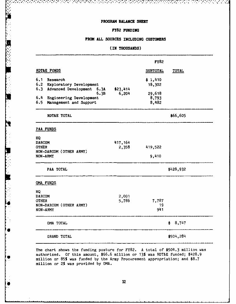
PROGRAM BALANCE SHEET
FY82 FUNDING
FROM ALL SOURCES INCLUDING CUSTOMERS
(IN THOUSANDS)
FY82
RDT&E FUNDS SUBTOTAL TOTAL
6.1 Research $ 1,4106.2 Exploratory Development 18,3026.3 Advanced Development 6.3A $23,414
6.3B 6,204 29,6186.4 Engineering Development 8,7936.5 Management and Support 8,482
RDT&E TOTAL $66,605
PAA FUNDS
HQDARCOM 417,164OTHER 2,358 419,522NON-DARCOM (OTHER ARMY)NON-ARMY 9,410
PAA TOTAL $428,932
OMA FUNDS
HQDARCOM 2,001OTHER 5,786 7,787NON-DARCOM (OTHER ARMY) 19NON-ARMY 941
OMA TOTAL $ 8,747
GRAND TOTAL $504,284
The chart shows the funding posture for FY82. A total of $504.3 million wasauthorized. Of this amount, $66.6 million or 13% was RDT&E funded; $428.9
6 million or 85% was funded by the Army Procurement appropriation; and $8.7million or 2% was provided by OMA.
32
. . . . .. . . . . . . . . . . . .-. . . . .- . . .
TECHNIAL ACHEVEMNT BY PR OGRAM DI=KOUr
TANK-AUTOOTIE CMNCMI LABORATORY
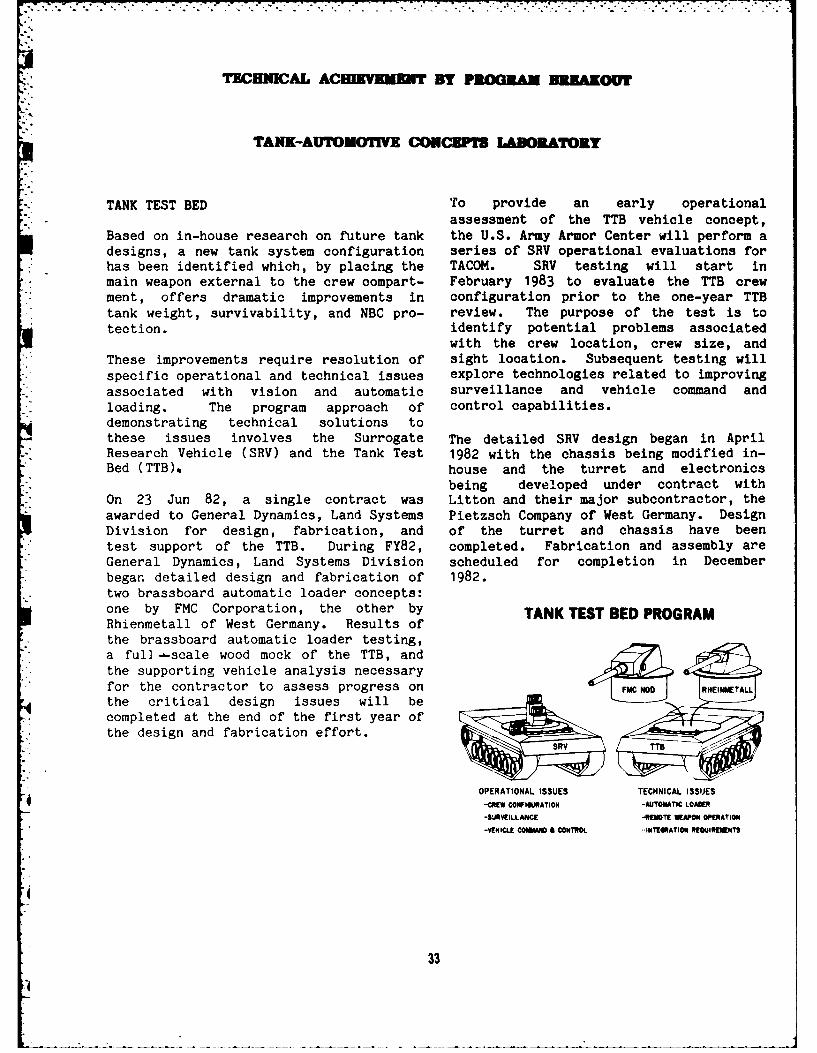
TANK TEST BED To provide an early operationalassessment of the TTB vehicle concept,
Based on in-house research on future tank the U.S. Army Armor Center will perform adesigns, a new tank system configuration series of SRV operational evaluations forhas been identified which, by placing the TACOM. SRV testing will start inmain weapon external to the crew compart- February 1983 to evaluate the TTB crewment, offers dramatic improvements in configuration prior to the one-year TTBtank weight, survivability, and NBC pro- review. The purpose of the test is totection. identify potential problems associated
with the crew location, crew size, andThese improvements require resolution of sight location. Subsequent testing will
- specific operational and technical issues explore technologies related to improvingassociated with vision and automatic surveillance and vehicle command andloading. The program approach of control capabilities.demonstrating technical solutions tothese issues involves the Surrogate The detailed SRV design began in AprilResearch Vehicle (SRV) and the Tank Test 1982 with the chassis being modified in-Bed (TTB),. house and the turret and electronics
being developed under contract withOn 23 Jun 82, a single contract was Litton and their major subcontractor, theawarded to General Dynamics, Land Systems Pietzsch Company of West Germany. DesignDivision for design, fabrication, and of the turret and chassis have beentest support of the TTB. During FY82, completed. Fabrication and assembly areGeneral Dynamics, Land Systems Division scheduled for completion in December
*began detailed design and fabrication of 1982.* two brassboard automatic loader concepts:
one by FMC Corporation, the other by TANK TESTBEDPROGRAMRhienmetall of West Germany. Results ofthe brassboard automatic loader testing,a full -scale wood mock of the TTB, andthe supporting vehicle analysis necessaryfor the contractor to assess progress on FMCROD RHEINMTALL
the critical design issues will becompleted at the end of the first year of
* the design and fabrication effort.•R TT5
OPERATIONAL ISSUES TECHNICAL ISSUES
-CREW CONFIGURATION -AUTOMATIC LOADER
-SURVEILLANCE -REMOTE WEAPON OPERATION
-VEHICLE COMAN & CONTROL. INTEGRATION REQUIREMENTS
33
-4 . . . .. ... .
TUC ICAL ACRE VEEMI rS PROGaML DIAKU
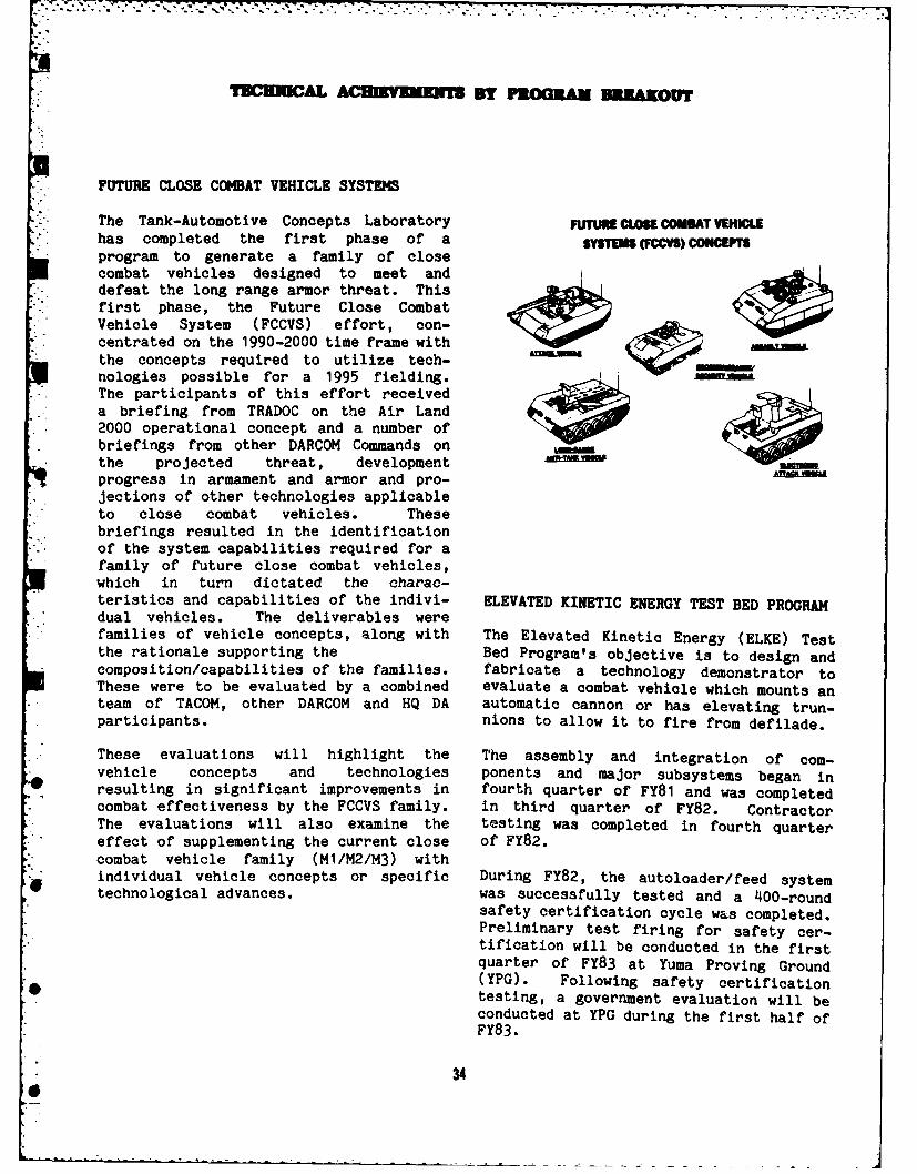
FUTURE CLOSE COMBAT VEHICLE SYSTEMS
The Tank-Automotive Concepts Laboratory FUTURE CLOSE COMBAT VEHMLEhas completed the first phase of a S1SEM (MM)CONCETprogram to generate a family of closecombat vehicles designed to meet anddefeat the long range armor threat. This
* first phase, the Future Close CombatVehicle System (FCCVS) effort, con-centrated on the 1990-2000 time frame withthe concepts required to utilize tech-nologies possible for a 1995 fielding.
* The participants of this effort receiveda briefing from TRADOC on the Air Land2000 operational concept and a number ofbriefings from other DARCOM Commands onthe projected threat, developmentprogress in armament and armor and pro-jections of other technologies applicableto close combat vehicles. These
'. briefings resulted in the identificationof the system capabilities required for afamily of future close combat vehicles,which in turn dictated the charac-teristics and capabilities of the indivi- ELEVATED KINETIC ENERGY TEST BED PROGRAMdual vehicles. The deliverables werefamilies of vehicle concepts, along with The Elevated Kinetic Energy (ELKE) Testthe rationale supporting the Bed Program's objective is to design andcomposition/capabilities of the families, fabricate a technology demonstrator toThese were to be evaluated by a combined evaluate a combat vehicle which mounts anteam of TACOM, other DARCOM and HQ DA automatic cannon or has elevating trun-participants. nions to allow it to fire from defilade.
These evaluations will highlight the The assembly and integration of com-vehicle concepts and technologies ponents and major subsystems began inresulting in significant improvements in fourth quarter of FY81 and was completedcombat effectiveness by the FCCVS family. in third quarter of FY82. ContractorThe evaluations will also examine the testing was completed in fourth quartereffect of supplementing the current close of FY82.combat vehicle family (M1/M2/M3) withindividual vehicle concepts or specific During FY82, the autoloader/feed systemtechnological advances, was successfully tested and a 400-round
safety certification cycle was completed.Preliminary test firing for safety cer-tification will be conducted in the firstquarter of FY83 at Yuma Proving Ground(YPG). Following safety certificationtesting, a government evaluation will beconducted at YPG during the first half ofFY83.
34
TECHIC AL ACDIEVMN'1B DY PROGRAM BR AKOUr
required before any test soldier could be-trained. Results of this evaluation led
....7, , . to an airworthiness release by AVRADCOMwhich TRADOC required before a safetyrelease could be issued. The safetyrelease permitted the test soldiers to
.4 perform free-flight operations duringtraining and CEP testing.
The data obtained from the CEP testing' - -- will be used by the US Army Infantryd School (USAIS) to formulate a decision
concerning further development of theILD. The USAIB found that selected testsoldiers with no previous flight trainingcan be trained to operate the ILD, andtrained operators can identify specifiedcontrol points and objectives whileoperating the ILD over a pre-plannedroute.
In 1983 TACOM plans to test the WASP IIas part of the High Technology Test BedRapid Deployment Force evaluations taking
The ELKE Test Bed will allow the develop- place in Yakima, Washington. These eva-" ment and evaluation of new tactics uti- luations will determine the operational
lizing defilade positioning and provide a capabilities of the system when utilizedtechnology base for the assessment of as part of the Army's Light Division forceweapon dynamics, auto-loaders, and fire structure.control requirements of future weaponssystems.WILLIAMS AERIAL SYSTEM PLATFORM (WASP II)
In June 1982, the Williams Aerial Systems
Platform (WASP II), built under contract
by TACOM, successfully completed ConceptEvaluation Program (CEP) testing by theUS Army Infantry Board (USAIB) at Ft.Benning, GA. The test objectives were todetermine if selected test soldiers withno previous flight training could betrained to operate an Individual LiftDevice (ILD), and to provide data onfunctional performance, limited main-tainability, logistics, human factors andsafety concerning operation of the WASP.
Since the ILD is not intended to beoperated by rated aviators, a PreliminaryAirworthiness Evaluation (PAE) was
35
TECHICMAL ACHIEVEMENTS BY PROGRAM BREAKOUT
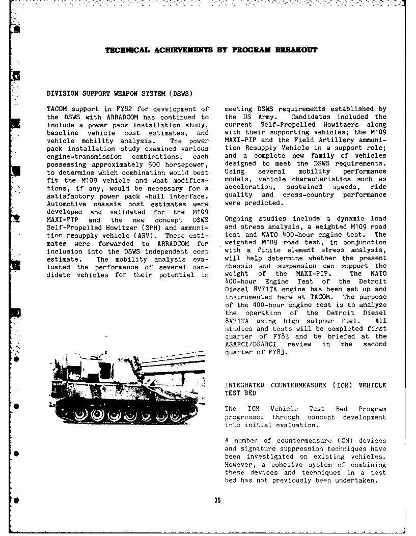
DIVISION SUPPORT WEAPON SYSTEM (DSWS)
TACOM support in FY82 for development of meeting DSWS requirements established by* the DSWS with ARRADCOM has continued to the US Army. Candidates included the
include a power pack installation study, current Self-Propelled Howitzers alongbaseline vehicle cost estimates, and with their supporting vehicles; the M109vehicle mobility analysis. The power MAXI-PIP and the Field Artillery ammuni-pack installation study examined various tion Resupply Vehicle in a support role;engine-transmission combinations, each and a complete new family of vehiclespossessing approximately 500 horsepower, designed to meet the DSWS requirements.to determine which combination would best Using several mobility performancefit the M109 vehicle and what modifica- models, vehicle characteristics such astions, if any, would be necessary for a acceleration, sustained speeds, ridesatisfactory power pack -hull interface, quality and cross-country performanceAutomotive chassis cost estimates were were predicted.
*developed and validated for the M109MAXI-PIP and the new concept DSWS Ongoing studies include a dynamic loadSelf-Propelled Howitzer (SPH) and ammuni- and stress analysis, a weighted M109 road
* tion resupply vehicle (ARV). These esti- test and NATO 400-hour engine test. Themates were forwarded to ARRADCOM for weighted M109 road test, in conjunctioninclusion into the DSWS independent cost with a finite element stress analysis,estimate. The mobility analysis eva- will help determine whether the presentluated the performance of several can- chassis and suspension can support thedidate vehicles for their potential in weight of the MAXI-PIP. The NATO
400-hour Engine Test of the DetroitDiesel 8V71TA engine has been set up andinstrumented here at TACOM. The purposeof the 400-hour engine test is to analyzethe operation of the Detroit Diesel8V71TA using high sulphur fuel. Allstudies and tests will be completed firstquarter of FY83 and be briefed at theASARCI/DSARCI review in the second
-. quarter of FY83.
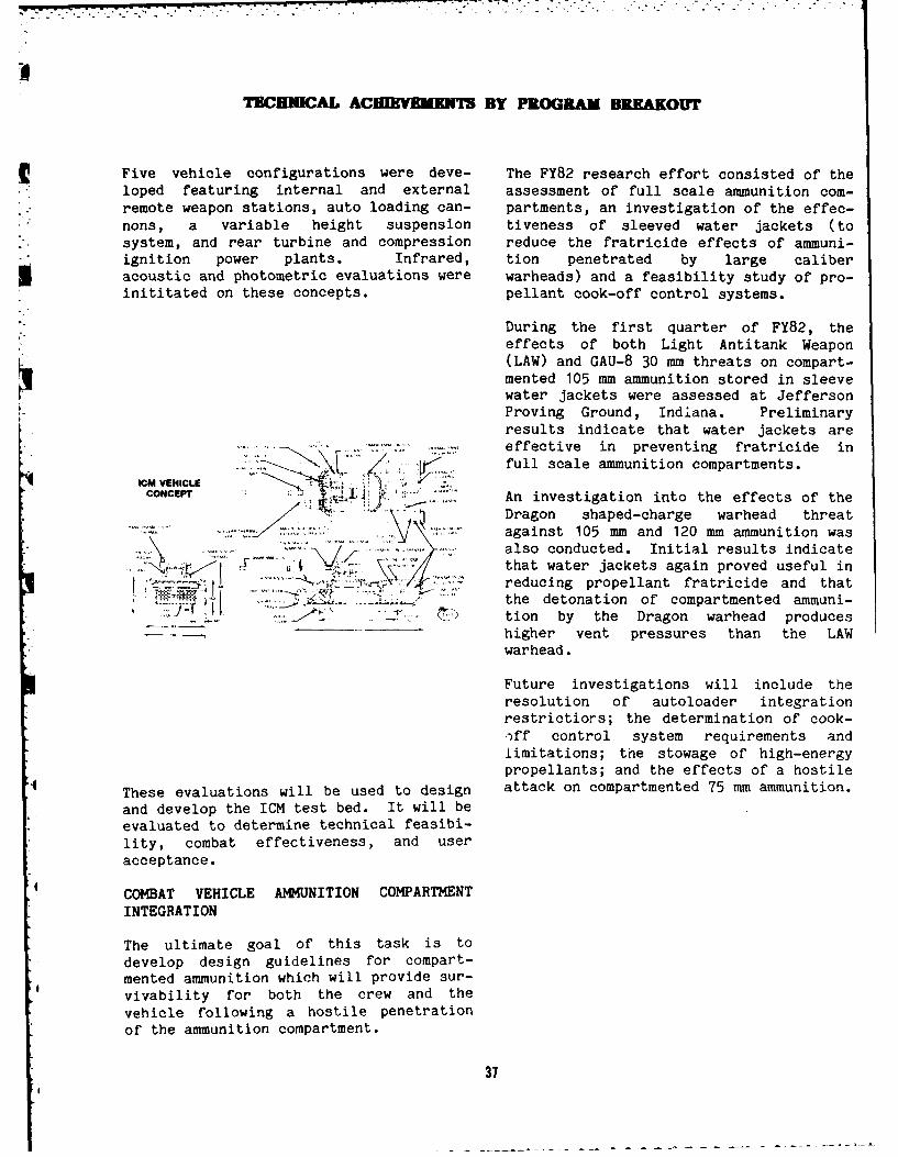
"y ~ i~i 'INTEGRATED COUNTERMEASURE (ICM) VEHICLE4.. TEST BED
The ICM Vehicle Test Bed Programprogressed through concept developmentinto initial evaluation.
A number of countermeasure (CM) devices
and signature suppression techniques have*O been investigated on existing vehicles.
However, a cohesive system of combiningthese devices and techniques in a testbed has not previously been undertaken.
*e 36
r ~ ~ ~~ ~ ~ ~ ~~~~~ ,- , . . . . , .. ._. .. ,' . . . .." -" , . .-. . -'. "-.
TBCHNICAL ACIHMENWf BY PROGRAM BR.AKOUT
Five vehicle configurations were deve- The FY82 research effort consisted of theloped featuring internal and external assessment of full scale ammunition com-remote weapon stations, auto loading can- partments, an investigation of the effec-nons, a variable height suspension tiveness of sleeved water jackets (to
" system, and rear turbine and compression reduce the fratricide effects of ammuni-* ignition power plants. Infrared, tion penetrated by large caliber
acoustic and photometric evaluations were warheads) and a feasibility study of pro-inititated on these concepts. pellant cook-off control systems.
During the first quarter of FY82, theeffects of both Light Antitank Weapon(LAW) and GAU-8 30 mm threats on compart-mented 105 mm ammunition stored in sleevewater jackets were assessed at JeffersonProving Ground, Indiana. Preliminaryresults indicate that water jackets areeffective in preventing fratricide in
Z full scale ammunition compartments.ICU VEHICLECONCEPT , .. .. An investigation into the effects of the
Dragon shaped-charge warhead threatagainst 105 mm and 120 mm ammunition was
. .:..- - ." also conducted. Initial results indicate
* ~..that water jackets again proved useful inreducing propellant fratricide and thatthe detonation of compartmented ammuni-
...... . ... .... tion by the Dragon warhead produceshigher vent pressures than the LAWwarhead.
Future investigations will include theresolution of autoloader integrationrestrictiors; the determination of cook-*-ff control system requirements andlimitations; the stowage of high-energypropellants; and the effects of a hostile
These evaluations will be used to design attack on compartmented 75 mm ammunition.
and develop the ICM test bed. It will beevaluated to determine technical feasibi-lity, combat effectiveness, and useracceptance.
COMBAT VEHICLE AMMUNITION COMPARTMENTINTEGRATION
The ultimate goal of this task is todevelop design guidelines for compart-mented ammunition which will provide sur-vivability for both the crew and thevehicle following a hostile penetrationof the ammunition compartment.
31
TECHNICAL ACIEVEMENT BY PROGRAM BREAKOUT
VEHICLE EFFECTIVENESS TECHNOLOGY FY82 systems: candidate systems for the Division* ACCOMPLISHMENTS Support Weapon System (including existing
self-propelled howitzers along with newThe first developments under the Vehicle vehicle concepts for self-pripell -Effectiveness Technology (VET) system howitzers); a mobility performance comparisonbegan to show a return to TACOM in fiscal for the standard M151A2 a-ton truck versus a1982. The "mini" VET became operational, generic light attack vehicle being eviluatedand streamlined the ongoing vulnerability by the 9th Infantry; several candidateand survivability analysis of combat vehicles for the Light Air Defense Systemvehicles by the Tank-Automotive Concepts (LADS); and several candidate vehicles forLaboratory. Programs for interactive the Army Maintenance Vehicle/Medicaldata input and data consistency checking Evacuation Vehicle (AMV/MEV).in several mobility analysis models havealso been completed, and are increasing Weapon station firng stability analyses werethe productivity of TACOM engineers. At performed for a variety of large caliber mainpresent these programs are being used as weapon systems. Vehicle dynamics simulationstand-alone tools, although they will models were exercised to determine the firingeventually be incorporated into the VET stability of new combat vehicles employing asystem. When the technical documentation variety of large caliber weapon3, includingis completed early in fiscal 1983, these the 120 mm cannon and the 145 mm TCAS cannon.programs will be available to outside It was determined that it is possible to fireusers of the mobility models. up to a 145 mm cannon from a 60-ton class
vehicle. Preliminary results have also shown
Other developments in the VET task are that standard M68 cannon systems must bethe computer/computer and computer/man modified through longer recoil or m[,zzleinterfaces that will be necessary for the breaks in order to be fired from a 20-tonanalysis capability in the full VET class vehicle.system. A prototype computer/computerinterface between the CAD system in the A target area hit probability evaluationConcepts Laboratory and the Prime com- methodology was established to predict hitputers in the Systems Laboratory enables probabilities for stationary targets.the data for a vulnerability model to be Initial results using this simulation modelextracted from the CAD data base and sent indicated that a 15 percent to 20 percent
* directly to the Prime computer where the decrease in hit probability may be expectedmodel will run. Future effort will if an external remote weapon station is
4 broaden the capabilty to include data for integrated into heavy tank design instead ofother models. 'he traditional full turret.
COMBAT VEHICLE ANALYSIS AND EVALUTION Initial assessments were conducted on the
Future Close Combat Vehicle Systea, pointing
Dynamic evaluations including mobility, out that additional vehicle functions such as
firing stability, hit probability, sur- high energy lasers and long range anti-tank
vivability and design trade offs were under- subsystems may be required to support the
taken on a number of combat vehicle concepts future air/land battle 2000.
and near term prototypes. Some of the majorassessments are listed below.
Mobility analyses and evaluations were con-ducted using the NATO Reference MobilityModel (NRMM) on the following vehicle
38
I
__ .- -... . - . - -. -- w " . . . .
TEGHUAL ACBIK VIE W Y PROGRAM BREAKOr
COMPUTER MODELING OF VEHICLE SIGNATURESAND SIGNATURE SUPPRESSION HARDWARE
" PERFORMANCE
Computer modeling techniques are nowavailable to model the signature ofpostulated vehicles in theinfrared/thermal spectral regions. Themodel can predict the surface te -peratures of various regions of a conceptvehicle's exterior and display them ingraphic form for numerous azimuthal andelevation look angles. Using this modelas an aid, the effectiveness of SignatureSuppression hardware can be evaluated interms of reduced vehicle vulnerabilty todetection by sensory systems. A portionof the model is made up of a weaponsystem performance subroutine whichaccepts modeled signature data and criti-ques the vehicle in terms of its vulnera-bility to a number of thermally basedweapon systems.
.3
39
TECHNICAL ACEIKYBMENT BY PROGRAM BREAKOUT
TANK-AUTOMOIVE SYSTEMS LABORATORY
HIGH PERFORMANCE CONE BRAKE
OVERHEAD ARMOR PROTECTIONThe high performance cone brake (HPCB)
Data received from Aberdeen Proving project objective was to modify commer-Ground on tests conducted in FY82 indi- cially available cone brakes to fit ancate a variety of composite plate struc- M939 5-ton truck. Comparison tests oftures that can be used either the standard air brake system against thestructurally, or as appliques, to roof HPCB were conducted and evaluated forarmors to prevent crew compartment brake performance, heat rejection and forpenetration of either jets from M-42 the ability to expel contaminants. TwoHEAT or fragments from STAFF type SFF sets of brake lining were used on themunitions. Computer generated data from standard brakes during the six 8,000 stopthe Ballistics Research Lab further cycle test. Normal wear was observed.indicates that such structures offer pro- The HPCB also used two sets of braketection factors of the order of 6 to 8 lining; in addition, it required thefrom nuclear radiation. This is due to a rebuild of the cone brake actuator unittwo-inch polyethylene layer on the inside of and installation of new pistons. The
. the roof and turret of a tank. Further latter test was concluded after 572 stopwork along this line including ceramics, cycles due to excessive heat build-up andaluminum, glass, polymerics, borated and loss of inner brake lining. This projectlitherated doped resin is being funded at was terminated during the Phase I effortthe Army Materials & Mechanics Research because the excessive heat retainingCenter and BRL for a combined amount of characteristics of the HPCB assembly can-$850,000 in FY83. not be controlled. The HPCB brake
assembly must be redesigned.ARMOR DEVELOPMENT AND DEMONSTRATION
0 This armor project is aimed at rapid MILITARY ELASTOMERSassessment and assimilation of armortechnology and the integration of both The finite element analysis codes andtraditional and non-traditional sur- math models for the fundamentals ofvivability measures in combat vehicles. elastomers (track pads) have been inputThe program includes overhead and appli- into the TACOM scientific computerque armor systems, the prototyping of system. Programs have been undertaken inadvanced armor designs, and computer fracture analysis of viscoelasticmodeling to determine vehicle vulnerabi- materials, damage accumulations, cracklity and survivability, initiations, and crack propagations.
Additionally, a program was initiated with The aim is to assure adequate dispersionthe Jet Propulsion Laborntory to take capacity in materials and to establishadvantage of lightweight materials tech- standards for acceptable dispersionnology in the design and fabrication of a of energy, stress, and temperatkire over alightweight armor structure. large area.
* 40
TECHNICAL ACEIOVWMENT BY PROGRM BREAKOUT
M939 SERIES 5-TON TRUCK DESIGN FOR BALLISTIC SHOCKS
The M939-Series 5-Ton Truck achieves Under contract, Southwest Research Inc.,* increased mobility, durability, and ser- has conducted ballistic shock tests. An
viceability, while retaining maximum analytical shock methodology has beenpossible parts interchangeablity with the established and validated to provide aM809-Series 5-ton truck. design for mounting systems of internal
components in combat vehicles. TheA contract for production was awarded to approach can be used to enhance protec-AM General Corp. on 8 April 1981 and tion against external ballistic shock.delivery of Initial Production Test (IPT)vehicles began in January 1982. Six IPT NEW MATERIALS AND PROCESSINGvehicles underwent 120,771 miles of dura-bility tests and two performance tests. TACOM has created a program for ballisticThe five year contract entails production screening of new or novel armorof 11,394 vehicles in support of Army, materials or systems. The program isAir Force, and Marine requirements with a being used for unsolicited proposals that100% increase option provision. The produce new or novel materials foraward of a System Technical Support ballistic evaluation.Contract on 24 April 1981 made availablethe increased manpower necessary to apply A standardization program has beencurrent industry expertise and production established for review of materials ortechnology to the Technical Data Package. processes and for subsequent ballistic
* The initial operation capability date for screening tests at Aberdeen Proving Ground.this system is February 1983.
SUPPLEMENTAL ARMOR ENGINEERING SUPPORT
Technical support was provided to the M9Armored Combat Engineer vehicle ProjectManager in the development, direction,and analysis of ballistic test programs.
" These programs include evaluation ofballistic protection capabilities for theM9 engine grille, and a recommendedcourse of action for the appliquesteel/aluminum arm,- program.
VEHICLE HARDENING
This program has been transferred from.... .- MERADCOM to TACOM. The present concept
-'"uses a single nonmetallic road wheel
which runs in a groove in a polyurethaneencapsulated steel track. This wheel canwithstand a 12.5 lb. land mine. Thisprogram was unfunded in FY81 and FY82,but has been reinstated for FY83.
41
.... . . . ..- .- - .-.-... . .'C '' . " .'. .- / ' - . . "
TECHNICAL ACHIEVENMEN I BY PROGRAM BREAKOUT
ADVANCED SUSPENSION SYSTEMS and are partially encased in rubber topermit slight yielding as driving loads
* The Advance Suspension Systems program is are applied. The objectives are:i set up to meet the increasing demands put improved track engagement; reduced
on the suspension system of recently loading, noise, and vibration; andfielded and future tracked military improved track and sprocket life. A set
- vehicles. In FY83, actuator seals for of sprockets has been fabricated andhydropneumatic suspension systems will be testing has been initiated on an M113developed to increase the RAM-D of the armored personel carrier.
* hydropneumatic suspension systems. Also,a pneumatic-spring, hydraulic-damping, Track tension adjustment system - thisin-arm suspension system will be eva- system will permit the driver to monitorluated for possible vehicle application and adjust track tension while thein the 20-25-ton weight class of vehicle is underway. The objective is tovehicles, maintain optimum track tension to eliminate
track loss and assure satisfactoryLOOPWHEEL SUSPENSION vehicle performance. An automatic ten-
sioning device is being designedin-house.
The Loopwheel Suspension Program wasestablished to evaluate the feasibility Roadwheel with replaceable tire - theof the loopwheel concept for military assembly includes a stamped-steelautomotive vehicles. This concept elimi- roadwheel, non-bonded rubber tire, and anates such components as roadwheel arms, steel wear-ring/tire retainer. Benefits
* roadwheels and torsion bars, and has the include field replacement of tires and* potential for providing a lighter, elimination of depot rebuilding.
simpler suspension system. During FY82, Roadwheel assemblies have been fabricatedcore life was increased from 400 - 1,200 and laboratory tested, and are beingmiles to 3,000 - 14,000 miles field-tested on the M113.
(accumulated on the moving belt dynamo-meter). A loop durability of 3,000miles on the loop wheel development ADIABATIC DIESEL ENGINEvehicle dynamometers was achieved.
A significant increase in core life led The goal of the adiabatic diesel engineto the discovery of more hardware program is to apply high-temperature,
problems, such as several strap break- insulating materials within the cor-ages. There is no plan to continue this bustion system of a diesel engine to
program in FY83 due to insufficient allow a drastic reduction in lost heat to
progress in development of this high risk tecolingdand exust systems.item.the cooling and exhaust systems.item.
Advantages of the adiabatic engine
include virtual elimination of the con-
vential cooling system, a 30% improvement
in fuel economy over current diesel engi-nes, and a 40% reduction in engine system
TRACK RETENTION AND CONTROL size and weight. Elimination of the
entire engine cooling system can produceDrive sprocket with resilient teeth - the a quantum jump in engine reliabilty andteeth are mounted on the sprocket body maintainability. Over 50% of engine
42
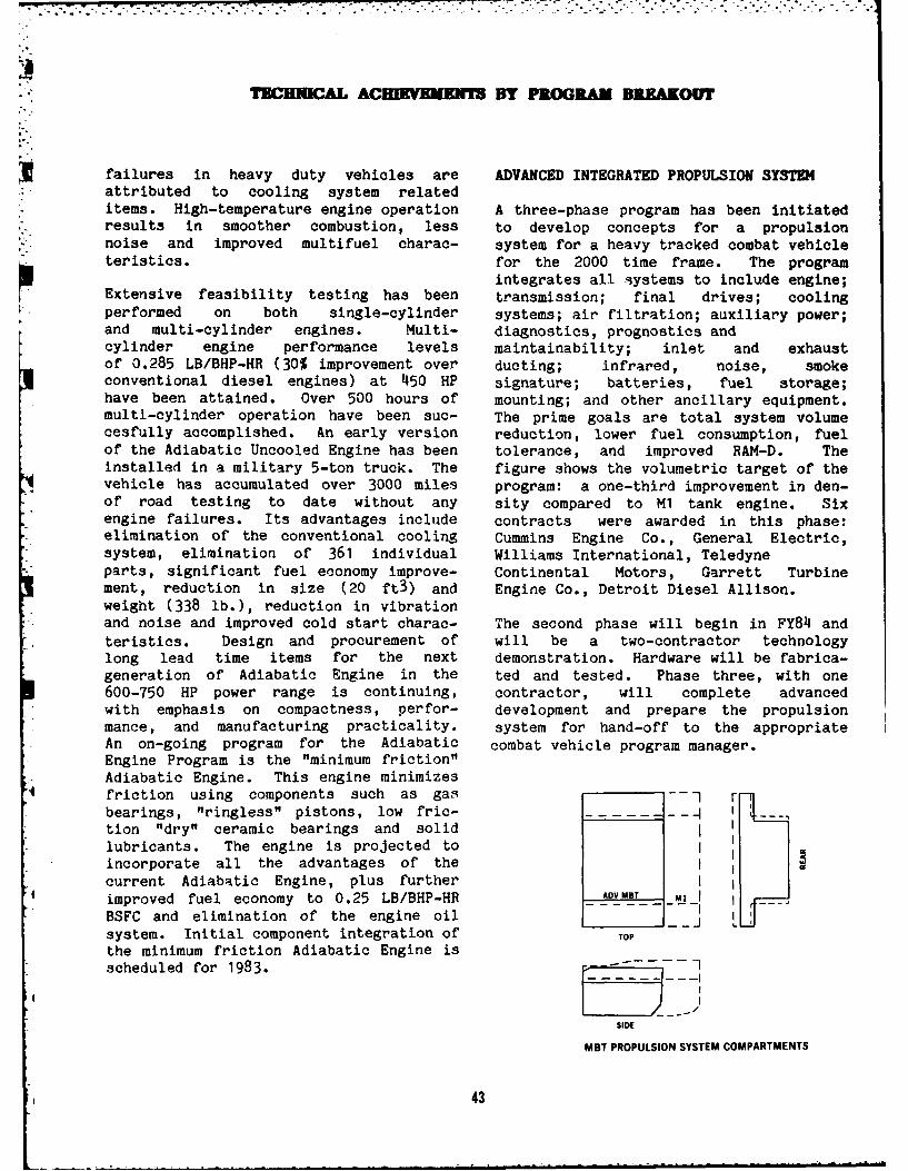
TBE1WAL ACEIMINEIN1M BY PROGRALM BRAKOUr
failures in heavy duty vehicles are ADVANCED INTEGRATED PROPULSION SYSTEMattributed to cooling system relateditems. High-temperature engine operation A three-phase program has been initiatedresults in smoother combustion, less to develop concepts for a propulsionnoise and improved multifuel charac- system for a heavy tracked combat vehicleteristics. for the 2000 time frame. The program
integrates all iystems to include engine;Extensive feasibility testing has been transmission; final drives; coolingperformed on both single-cylinder systems; air filtration; auxiliary power;and multi-cylinder engines. Multi- diagnostics, prognostics andcylinder engine performance levels maintainability; inlet and exhaustof 0.285 LB/BHP-HR (30% improvement over ducting; infrared, noise, smokeconventional diesel engines) at 450 HP signature; batteries, fuel storage;have been attained. Over 500 hours of mounting; and other ancillary equipment.multi-cylinder operation have been suc- The prime goals are total system volumecesfully accomplished. An early version reduction, lower fuel consumption, fuelof the Adiabatic Uncooled Engine has been tolerance, and improved RAM-D. Theinstalled in a military 5-ton truck. The figure shows the volumetric target of thevehicle has accumulated over 3000 miles program: a one-third improvement in den-of road testing to date without any sity compared to M1 tank engine. Sixengine failures. Its advantages include contracts were awarded in this phase:elimination of the conventional cooling Cummins Engine Co., General Electric,system, elimination of 361 individual Williams International, Teledyne
i parts, significant fuel economy improve- Continental Motors, Garrett Turbinement, reduction in size (20 ft3) and Engine Co., Detroit Diesel Allison.weight (338 lb.), reduction in vibrationand noise and improved cold start charac- The second phase will begin in FY84 andteristics. Design and procurement of will be a two-contractor technologylong lead time items for the next demonstration. Hardware will be fabrica-generation of Adiabatic Engine in the ted and tested. Phase three, with one600-750 HP power range is continuing, contractor, will complete advancedwith emphasis on compactness, perfor- development and prepare the propulsionmance, and manufacturing practicality, system for hand-off to the appropriateAn on-going program for the Adiabatic combat vehicle program manager.Engine Program is the "minimum friction"Adiabatic Engine. This engine minimizesfriction using components such as gas --1 rbearings, "ringless" pistons, low fric-tion "dry" ceramic bearings and solidlubricants. The engine is projected toincorporate all the advantages of the Icurrent Adiabatic Engine, plus furtherimproved fuel economy to 0.25 LB/BHP-HR AMYMBI Ml
BSFC and elimination of the engine oil Isystem. Initial component integration of TOP
the minimum friction Adiabatic Engine isscheduled for 1983.
SIDE
MBT PROPULSION SYSTEM COMPARTMENTS
43
.TECHNICAL AC]MIVBLIT BY PROGRAM BREAKOUT
HIGH MOBILITY MULTIPURPOSE WHEELED Schedules and cost estimates have been
VEHICLE (HM9WV) prepared for R&D prototype in-housedesign, fabrication, production, and
The High Mobility Multipurpose Wheeled fielding. Execution of this mine
Vehicle (HMMWV) is a light, highly mobile clearing vehicle program awaits alloca-
vehicle consisting of a 4x4, 14-ton com- tion of funds.
mon chassis and various kit applica-tions for joint service vehicle roles.These roles include weapons carrier, com- M989 - 11-TON HEAVY EXPANDED MOBILITYmunications vehicle, utility vehicle, AMMUNITION TRAILER (HEMAT)ambulance and target acquisition vehicle.The HMMWV is to replace the following The HEMAT is a heavy duty tandem axlevehicles: (a) Truck, Utility, -Ton, 4x4 trailer designed to carry four MultipleM151 Series: (b) Truck, Platform, Uti- Launch Rocket System (MLRS) pods or
lity, &-Ton, 4x4 M274 Series; (c) Truck, various ammunition pallet configurations.
Cargo, Commercial, 1 -Ton, 4x4 and 4x2 The HEMAT is the companion trailer for
M880 Family (d) Truck, Cargo, 1 -Ton, 6x6 the HEMTT - M985 Heavy Expanded Mobility
M561, and (e) Truck, Tactical, Ambulance Tactical Truck. The trailer is also com-
1 -Ton, 6x6 M792. HMMWV vehicles will patible with the Self Propelled Loader
have a diesel engine, automatic Launcher (SPLL - a track vehicle) in case
* transmission, run-flat tires and be able of emergency. Miller Tilt-Top built 18
to accelerate from 0 to 30 miles per hour vehicles prior to stopping production due
in six (desired) to eight (required) to financial difficulties. The vehicles* seconds with a 300-mile crusing range. have been tested at the Waterways
- The vehicle operating profile will be 40 Experiment Station, Savanna, GA and Ft.percent cross-country, 30 percent paved Sill, OK. A novation agreement has been
highway and 30 percent secondary roads, finalized for Stowell Industries to buildTo the maximum extent possible, existing HEMAT trailers under the terms of the
military or reliable commercial com- Miller Tilt-Top multiyear contract.
ponents shall be used. First production delivery from StowellIndustries is scheduled for Dec 82.
Contracts were awarded to three contrac-
tors on 1 Jul 81 to design/build 11 pro-
totypes each. Vehicles were delivered
for testing on 27 Apr 82. An Integrated M871 SEMITRAILER, 221 TON
Development/Operational Competitive testwas conducted and completed during FY82. The M871 is a 30-foot tandem axle flatbed
Additional follow-on testing is planned semitrailer capable of carrying con-
for FY83 and contracts are scheduled to tainers, missiles, or breakbulk cargo
be awarded on 1 Feb 83 for initial pro- weighing up to 221 tons. The M871, along
duction on a five year multi-year basis; with the M872, will replace the M127 Semi-
and for R&D efforts to refurbish proto- trailer fleet. The prime movers are the
types and design additional kits. 5- and 8-ton military truck tractors and
the commercial International 4070A truck
tractor. The M871 trailer with the M915
ROBOTIC OBSTACLE BREACHING ASSUALT TANK truck tractor has been operational in
a (ROBAT) Germany since Feb 82. A full release of
the M871 trailer was approved in Jul 82.
System responsibility for the ROBAT was A total of 3166 trailers will be built
assigned to TACOM in May 1982 by DARCOM. under the current five year contract.
6 44
"". HnuWAL ACEIIEE" ,,BY PROGRAM BREAKOV"
DOLLY SET, LIFT TRANSPORTABLE FMS TECHNICAL SUPPORT ACTIVITIES
The Dolly Set, Lift Transportable, XM1022 The Government of Egypt signed a Letterwill lift, transport and emplace the of Agreement in March 1981 to extend thefamily of Rigid Wall Shelters currently operational life of an anti-aircraftbeing procured by Natick Labs. The dolly defense system. TACOM is providing theis an NDI item designed to carry a gross management and technical expertise to thepayload of 15,000 lbs. It will be uti- contractor for the vehicle primary powerlized by the Surgeon General, Aviation supply system.Maintenance Activity and other ArmyAgencies. Multi-Service Application isanticipated. 1,000 HP ADVANCED DIESEL ENGINE
The program was assigned to TACOM in Sep81. Since that time Natick Labs has The 1,000 HP Advanced Diesel Enginecompleted development testing on the program objective is to improve theshelters which provided information on diesel engine's horsepower-to-weightprototype dollys from two companies; a ratio and fuel economy by applying dieselmarket survey has been initiated; and a technology to existing commercial-baseddraft specification has been written, engines. The goal is to develop a 1,000Type classification is scheduled for Feb horsepower engine. The advanced tech-83 with a procurement award expected by nology being applied includes a high-Nov 83. pressure, high-efficiency turbocharger, a
turbocompound system, low-compressionADVANCED TECHNIQUES FOR ELECTRICAL POWER ratio and an intake manifold burner toMANAGEMENT, CONTROL AND DISTRIBUTION aid in cold-starting and light-loadSYSTEMS (aTEPS) operation.
Testing of the ATEPS microcomputer- Initial testing of a diesel engine testcontrolled multiplex system in a baseline rig was completed during second quarterM1 tank hull was completed in FY82. Test FY82 at TACOM. The rig was a modifiedresults established ATEPS' feasibility. version of the Cummins VTA-903, 8Testing included 40 hours of static per- cylinder, 500 HP diesel engine used informance testing and a five hour TACOM the M2/M3 Infantry Fighting and Cavalrytest track test. The design of a two Fighting Vehicles. The turbocompoundterminal turret system was completed. engine successfully attained 1025 HP out-This system consists of a fire control put at 3200 RPM. The observed fuel con-remote terminal and gunners/crew ter- summption at this power level was 0.350minal, which interfaces with the current LB/HP-HR.five terminal hull system. Fabricationof the two terminals is in progress. The engine was sent back in 3rd Qtr FY82
to Cummins Engine Co. for further develop-O FY83 plans provide for the addition of a ment and testing. Through Sep 82 a total
third terminal which performs both remote of 355 test hours have been accumulatedterminal functions and crew terminal on the engine. Future work includesfunctions; it will also upgrade the development of a new cam and a variableexisting M1 ATEPS Prototype Hull System. injection timing system to enhance engineThe latter task will provide more performance throughout its entire speedreliable engine control capabilty for the range. Additional work will include aturret test phase. 200 hour durability test as well.
45
TECHNICAL ACEIKEfHII Y PROGRAM BREAKOUr
* HYDRAULIC BRAKE RETARDER
The present multiple wet-plate friction- A 1000 hour dynamometer durability test,type braking systems have been pushed to aborted last year after 219 test hours,the limits of friction brake technology, was restated in 1982 after further engineAs a result, increases in braking capa- development. This test is now nearingcity can only be obtained by adding more completion with mnre than 800 durabilityplates or by increasing their diameters, test hours logged. Both of the vehicleeither of which must be accompanied by engines mentioned above and the 1000 hourincreased application forces. This pro- test engine are equipped with VAT tur--mQtes early plate failure. bochargers and fully automatic VAT controls.
Hydraulic retarder-type braking systems ENGINE CONCEPTS FOR ALTERNATIVE FUELSsolve the increasing brake capacityproblem while avoiding the plate system This task continues efforts to establishproblems mentioned above, a technology base for development of
e halternative fuels combustion systems forThe hydraulic retarder operates on the military ground vehicle engines. Inprinciple of change of momentum of oil as FY85, several areas of new technologyit .irculates in a toroidal chamber, much will be investigated:
like the action of a torque converter.The initial hydraulic brake retarder 0 Microprocessor Controlled Fuel
* design, hardware procurement and shake- Injectiondown testing have been completed.Performance data resulting from the 0 Ancillary Componentry Modulationretarder testing has been used in makinga computer synthesis of vehicle and 0 Sensorscooling system behavior under varyingconditions of operation. The resulting 0 New Alternative Fuel Combustionretarder will be incorporated into the Processes1,000-HP transmission design.
0 Engine/Fuel Compatibility Provisions
1500 HP DIESEL ENGINE DEVELOMENT and combination of the above to developfull authority microprocessor controlled
0 The objective of this program is to con- combustion systems.
tinue development of a diesel engineuntil the Army ground turbine engine The current effort includes investigating
(AGT-1500) operates satisfactorily in the the complete spectrum of microprocessorM1 tank. fuel injection control systems to exploit
their precision and flexibility in using
* During 1982 two M1 pilot vehicles were alternative fuels; analyzing micropro-
modified with diesel powerpacks. The cessor modulation of ancillary com-
first vehicle was delivered to the ponentry, such as turbomachinery;Government in July 1982. It was tested evaluating new sensor techniques, withfor infrared signatures at Grayling, emphasis on combustion quality sensors;Michigan, then shipped to Yuma Proving investigating all known combustion pro-
Ground for desert testing. The second cesses suitable for alternative fuels, asvehicle was delivered to the Government well as new processes; and assessingin mid-October 1982 and shipped to engine/fuel compatibility with respect toAberdeen Proving Ground for 6000 mile RAM material, wear, lubricity, designtesting. tolerances, and similar factors.
46
TECHNICAL ACHIKVEMEWIS BY PROGRAM BREAKOUT
GROUND LAUNCHED CRUISE MISSILE (GLCM) COMMERCIAL UTILITY AND CARGO VEHICLE
Designs were completed for the fabrica- The Commercial Utility and Cargo Vehicletion of GLCM Driver Training Vehicles is intended to fulfill the Army light-(DTVs). This included storage and fuel load requirements (cargo, utility, andboxes, DTV dummy loads, Launch Control ambulance) for essentially rear areaCenter mounting brackets, driver training roles. These vehicles will replace partkits, launcher container, shelter of the M151A2 4-ton truck family and allmounting brackets, fiber optics box con- of the M880/890-series trucks. TACOMtainer, simulated launcher assembly, and will procure the various derivative
* ballast modules. Fabrication started and vehicles, using the production base of aportions of the Transporter Erector commercially available diesel engineLauncher (TEL) and Launch Control Center driven 4x4 vehicle for a family of trucks(LCC) vehicles were completed. Project with common configurations and logisticcompletion, in FY83, is proceeding on benefits.schedule.
Specific Army requirements includeADVANCED DIAGNOSTICS blackout lights, STE/ICE, NBC, driver
weapon security, and military towing pro-' The Advanced Diagnostics program will visions. Applicable kits include win-
provide the forward support mechanic a terization, machine gun, 24-voltsimple and effective means of diagnosing electrical system with 100-amp capacity,vehicle malfinctions rapidly. troop seats, cargo box cover, and com-
munication shelters.In FY82, the Advanced Diagnostics programinitiated a feasibility study of a A multi-year procurement contract wasSimplified Test Equipment (STE) system awarded 23 July 1982 to GM.incorporating noncontact/minimal contactdiagnostic test technology, as well ascomplete STE/ICE test capability, into areprogrammable test set. Such a test setprovides measurements for use indiagnosing tank-automotive components orsubsystems with a minimum of physicalcontact between the vehicle and the testa Asystem.
The Advanced Diagnostics program willcontinue to investigate advanceddiagnostic techniques concerned with non-contact sensor technology for gas turbine ,.
engines, fuel injection systems, and .
microprocessor-based engine controllers.Using a modified STE/ICE or limited STE-Xtest set, program members will test thediagnostic capabilities of the VariableReluctance Sensor and microwave sensor tomeasure engine speed, turbocharger con-dition, turbocharged engine power andcylinder fault identification.
47
TECHNICAL ACHIVEMEI BY PROGRAM BREAKOUT
AUXILIARY POWER UNIT (APU) EVALUATION OF GT-601 COMO4ERCIAL VEHICULAR
GAS TURBINE ENGINEThe APU development resulted in a gas- Aturbine-engine-driven 10 kw generator set Feasibility of the Garrett Corp GT-601capable of supplying 28VDC power to the engine was investigated in a 20-tonM1 and other combat vehicles. The first tracked combat vehicle using an Allisonphase of development was concluded with X-300 transmission without the torquethe laboratory and vehicle tests of the converter (not needed with this engine).five prototype units. Good results were Operational charactristics of the systemachieved with APU operation and were determined and later used in valida-APU-assisted main engine starts in the M1 tion of a computer modelling programwere obtained down to -70OF in under a which can provide alternate engine com-minute with minimal battery preheating parison data for future engine selection.
* and precharging. Final test phase is now in progressinvolving maneuverability, increased air
The next phase of development effort will cleaner blockage, and engine braking
upgrade the unit to a 15 kw output using effects. These are being run for com-
commercially available components. 4 parison with the M1 tank.
15 kw unit would allow "battery COMPOSITE ARMORunassisted" engine starts for the M1 atlow temperatures. Composite armor systems have been eval-
uated against the medium caliber (23 &A program will be initiated to silence 30 mm) high-velocity kinetic-energythe APU and further reduce its packaging ammuniton. Efficient, lightweight armorvolume within an M1 tank. This effort is systems of louver type design, have beenaimed at meeting the Army's needs for a developed. Methods have been developedmuch reduced signature and space availa- for attaching the armor to lightweight
- bility for fuel. vehicles.
SMALL UNIT SUPPORT VEHICLE (SUSV) A design using automotive sheet steel wasestablished to defeat small flechettes,
The SUSV is a helicopter-transportable splinters and fragments. The design wasvehicle that can traverse all kinds of both weight efficient and economical.terrain, year-round, either on-road orcross-country. The SUSV is intended to NOISE CONTROLsupport mobile units by transporting
* equipment, ammunition and supplies in During FY82, the near-field singlenorthern and mountainous regions. The microphone scanning technique was appliedvehicle was type classified as the to an M113A1 armored personnel carrier."Carrier, Cargo, Tracked, 11 ton, M973" Sound pressure fields were mapped for both
* as a result of the 10 - 11 February 1982 interior vehicle sides and door. TheseIn-Process Review. sound maps were used in low frequency
noise location.The market survey conducted in 1981resulted in the nomination of one can- The effect of a spall supressive armordidate vehicle which meets the SUSV system on the interior noise field of anrequirements. This vehicle is the M113 was also investigated. Results
6 Swedish built BV206 tracked vehicle. An indicate that the spall liner lowers theapproved sole-source procurement process interior noise field by an average valueis underway. Contract award and vehicle of 2 dB(A) for several vehicle test con-production will commence in FY83. ditions.
48
. .
TECHNICAL ACHEMVENET BY PROGRAM BREAKOUT
ADVANCE COMPOSITE MATERIALS & STRUCTURES
Prototype units of various components-- way and tactical operating requirements.frame, wheels, leaf springs, and drive As a result of these findings the XM1000shafts--have been manufactured from program has been redirected. The programfiberglass/epoxy resin and graphite/epoxy personnel are now looking at the feasibi-resin systems. The frame is manufactured lity of adopting commercial trailers tousing a fiberglass/graphite hybrid in the meet the tactical operating requirements.
* frame rails with fiberglass frame cross- Two commercial trailers are now beingmembers and wheels using both chopped and procured and will undergo technicaldirectional long fibers. The frame is feasibility testing in FY83.currently undergoing testing at the ArmyMechanics and Materials Research Center.All components are being assembled into LASER SURFACE HARDENED COMBAT VEHICLEan M939-series 5-ton cargo truck; comple- COMPONENTStion is targeted for 2nd Qtr FY83 with alimited field evaluation to follow. Recently completed research demonstrated
that surface hardening requirements forT-142 track end connectors and cen-
LASER HEAT TREATING - M2/M3 FIGHTING terguides can be adequately met by heatVEHICLE SYSTEMS treatment with a CO2 laser beam. The
necessary parametric limits and controlsto achieve desired hardening patterns for
In FY82, a program was started to the selected track components wereestablish production processes for M2/M3 established. One important achievementFighting Vehicle track and suspension is the development of unique methods ofcomponents which will use lasers to heat- laser heat treating by using mirrors or atreat selected high-wear areas. With cylindrical lens. These important deve-laser technology, both the location and lopments have opened new dimensions inthe depth of the area to be treated can laser heat treatment by utilizing lowbe controlled precisely. There will be laser beam power densities to achieve
* minimal distortion of the part due to the large casing geometries without surfaceheat treating process. A manufacturing melting.saving of approximately 5% throughreduced machining and an approximate 20% M2/M3 FIGHTING VEHICLE SYSTEMS COMPOSITEincrease in service life of the component WEAPON STATION BASKETcan be achieved.
The program to manufacture weapon sta-tion baskets which use composite manufac-
XM1000 - SEMITRAILER LOWBED 70 TON turing processes reduces fabrication costsby approximately 10%. Current production
The XM1000 is a non-development item fabrication consists of fixturing over 100(NDI) 70-Ton Heavy Equipment Transporter parts prior to welding. A productionSemitrailer capable of transporting the composite process will reduce the piecemain battle tank and other heavy tracked part count to 10, thus loweringand wheeled vehicles. Technical feasi- fabrication costs without affecting com-bility testing and a Military Traffic ponent performance. Other benefitsManagement Command state highway survey expected are greater corrosionhave shown that a Western Heavy Hauler resistance, lighter weight, and fieldtype trailer will not satisfy both high- repairability.
49
-. . .- . . .- - -
S- - > " - - ' r . T. -"h w f'. ; f 3 ' , . ,: " i " 'r. .- -- ' ;-,I..
TBCHICMAL ACE IMNEEN3 BY PROGRAM BREAKOUT
LIGHTWEIGHT SADDLE FUEL TANK
entire vehicles, was used to investigateFabrication of 5-ton cargo truck light- High Mobility/Agility Vehicle (HIMAG)weight fuel tanks for engineering eva- stabilization performance capabilitiesluation was completed in February 1982. for input into the Mobile Protected GunTesting is in progress at Yuma Proving MPG program. Several levels of gun unba-Grounds (YPG), AZ, at the Tropical Test lance tests were conducted to evaluateCenter (Panama Canal Zone) and at the system performance of fire-on-the-moveCold Region Test Center (CRTC) in Ft. capability.Greely, AK. Assessments of the light-weight fuel tank are scheduled for In a separate program, TACOM providedOctober 1982 at YPG and April 1983 at funding support to Human Engineering
, CRTC. All work is scheduled for comple- Laboratory for completion of the Firetion in FY83. Control Research System.
The lightweight saddle fuel tanks were TURRET AND WEAPON STATION INTEGRATIONfabricated for the 5-ton M809-seriescargo trucks, and are fully The turret and weapon station integrationinterchangeable with existing metal fuel program provides a coordinated effort fortanks used on the M809- and M939-series the development of advanced weapon sta-cargo trucks. The weights of the light- tion components, subsystems and tech-weight fuel tank and existing metal fuel niques resulting in demonstrabletanks, fully assembled and without fuel, state-of-the-art turret/weapon integra-are as follows: tion. Development activities during FY82
included Fluidic Tank Turreto Lightweight Fuel Tank (M809-series Stabilization and Position Control
cargo truck): 78.8 lb. (35.7 kg) System.
o M809 Metal Fuel Tank: 106 lb. (48.1 FLUIDIC TANK TURRET STABILIZATIONkg)
A brassboard model of a pneumatic rateo M939 Metal Fuel Tank: 209 lb. (94.8 sensor was developed, resulting in rede-
kg) sign of the pressure controlled oscilla-tors, which improved rate resolution and
The fuel capacity of all fuel tanks linearity. Other design changes in thementioned above is 78 gallons (295 fluidic amplifiers, vane pump andliters). electronics will reduce noise and improve
range and reliabilty. Delivery of the
*sensors for vehicle (Ml tank) tests is
FIRE CONTROL/WEAPON SYSTEMS INTEGRATION scheduled for second quarter FY83. Thesetests, to be performed during FY83, will
An objective of this program is to sup- provide data to document the improvement
port fire control technologies that have in stabilization of the M1 tank turret
potential application to current and system. Successful completion of this
future TACOM combat vehicle programs. phase of fluidic development will providea basis for a more extensive development
During FY82, the Full Scale Simulation of an all-pneumatic gun stabilization
Facility, which has the capacity to shake system for combat vehicles.
50
TECHICAL ACHEMENTS BY PROGRAM BREAKOUT
TURBINE ENGINE CERAMIC COMPONENTS Milford, and on an improved M109 SPhowitzer and M2 Infantry Fighting Vehicle
Studies have been made of heat transfer, at Aberdeen Proving Ground.*thermal stresses, cooling air flow and
turbine rotor configuration design at a M1/H60 NEAR-TERM TRACK IMPROVEMENTturbine inlet temperature of 26500F. PROGRAMThermal barriers provided by a ceramic Aprga hsben cedldt imov
* coating applied under metallic blades Aprga hsben cedldt ipovreduced the amount of heat flow to the the M1 and M60 tank tracks. This includes themetal and consequently reduced the cooling following:requirements of the metal. Increased0 Farcto an veil tst f
* operating temperature and reduced cooling0 Farcto an veil tst fair flow increased engine efficiency. C10146 steel pins, which will reduce trackThe final phase of this project is in pin breakage on the M60 vehicle.progress now. It will include fabrica-tion of complete ceramic coated turbine 0 A study of fasteners, which maystator and rotor, both of which will be improve reliability and maintainabilityevaluated in a test engine. Project is of track pads, end connectors and centerslated for completion in FY84. guides.
o Procurement and vehicle test ofM1 full area pad track, which will
TRACK FOR 15- TO 18-TON VEHICLES; XT-150 imrvtaclfe
o Procurement and test of variousThis track is a double pin, extended end rubber compounds which will improve theconnector design with quick track life on the M1 vehicle.disconnect/replaceable chevron pads.Second generation track has been tested 0 Development of a laboratoryfrom 6,000 to 10,000 miles at several test which will determine blowoutCONUS locations with good results. resistance of various compounds.
* Experimental track tests using variousfabrication methods are scheduled to 0 Development, fabrication andbegin at Nevada Automotive Test Center. vehicle test of a composite track pad for
M60 and M1 vehicles which will reduceblowout and cutting/chunking.
TRACK FOR 20- To 40-TON VEHICLES; XT-154 0 Development and vehicle test of awinter-traction device.
This track is a double pin, extended endconnector design with quickdisconnect/replaceable chevron pads. The POSITION CONTROL SYSTEM (PCS)first generation of the XT154 track,suitable for self-propelled artillery, The PCS involves a displacement sensitiveFAASV, and the Bradley vehicles has been trackball concept for controlling thetested at Aberdeen Proving Ground for turret/weapon drive system. PCS tracking2,000 miles. Second generation track is peformance tests were conducted on thebeing fabricated and is scheduled for TACOM Dynamic Ride Simulator at the endvehicle test on an M110 SP howitzer at of FY82. Analysis of the test data is inYuma Proving Ground, on an M108 gun at process.
51
TWCHNCAL ACHIEVMENTS By PROGRAM BREAKOiFF
MECHANICAL FASTENING OF COMPOSITE M2/M3 FIGHTING VEHICLE SYSTEM -
MATERIALS ADHESIVE TECHNOLOGY
Extensive use of fiber composite An FY82 project has been undertaken tomaterials in both structural and non- establish manufacturing methodology using
structural applications will require adhesives in the production of thea variety of joining techniques. M2/M3 Fighting Vehicles. Many interiorMechanical fasteners, such as bolts, hull components (for example, footmanscrews, and rivets, are inexpensive, loops) are currently attached bysimple and should be available to labor-intensive and costly welds. Manydesigners along with adhesives and other, small interior hull components now can bemore sophisticated, joining techniques. attached with adhesives, thus yielding anIn microscopically homogenous isotropic approximate cost savings of $200 permaterials, such as metals, the effect of vehicle. Other advantages include fieldmechanical fasteners on local stress repairability, reduced joint corrosiondistribution and stress concentration is and reduced component deformation.well knowm; these local effects die outrapidly away from the fasteners. Sucheffects are less well understood in com-posites, where local stresses may bechanneled over long distances, and wherestress effects depend strongly on struc-ture.
TACOM awarded a contract to MichiganState University in Aug 82 to performexperimental and analytical studies onstresses due to mechanical fasteners infiber composites. Results of these stu-dies will assist designers inestablishing fastener patterns, localreinforcement, and structural require-ments where composites are selected.
52
TECMICAL ACEIEVEMEWNT BY PROGRAM BREAKOUT
MOTORCYCLE: XM1030
The Motorcycle Program will follow a ners not be available during depottypical NDI acquisition cycle. The rebuild and field repair). Through themotorcycle's primary mission will be reduction of component rework--caused bymessage/courier service and will replace conventional hole tapping errors, brokensome M151 trucks in certain roles. it taps and cross threading in aluminum--will be an on-off road vehicle, not to this program has the potential to reduce
exceed 300 lbs., with an engine displace- manufacturing costs by approximatelyment of 250cc or higher. The letter $1,000 per vehicle.requirement for miltary motorcycle wasapproved in Sep 81. A TechnicalFeasibility Test was conducted between 17 GEAR DIE DESIGNJun and 30 Sep 82 on 15 motorcycles(three motorcycles each from five dif- Gear manufacturing processes are highlyferent manufacturers). specialized due to the complex geometry
t. and high accuracy requirements of gearteeth. Traditionally, bevel gears are
12-VOLT VEHICLE LIGHTING manufactured using highly specializedcutting and grinding machines. Precision
The 12-volt lighting project will provide forging of bevel gears offers con-a system for adapting commonly available siderable advantages because this process12-volt lamps for use in 24-volt military reduces the machining losses andvehicles. This system will eliminate the increases the fatigue life of the gear,.requirements for shock-mounting lights In FY82, ten-inch diameter spiral beve:with 24-volt lamps (24-volt lamps are gears were successfully forged to netprone to fail due to the extra fragile shape, thereby eliminating the need forfilaments). Vehicles at TACOM and machining, which represents 40% of theKeweenaw Research Center, at Houghton, end item cost if machined from blanks.MI, continue on test. In addition,three high-mileage test vehicles atAberdeen and the Ohio Test Center areemploying 12-volt lighting. These tests LOCKING ADHESIVES AND SEALANTS
will continue for a minimum of 20,000 The first phase of this two-phase programmiles. Targeted completion of the eval- valiat hese of omeria
uaio i 2dqurtr Y8.validates the use of commerciallyuation is 2nd quarter FY83. available anoerobic adhesives to replace
lockwashers and other mechanical devices.The sealants provide improved reliability
SELF-THREADING FASTENERS FOR THE M2 and and performance. These products are eva-M3 FIGHTING VEHICLE SYSTEMS luated through laboratory and field tests
on selected combat vehicles, engines andAn FY82 effort has been undertaken transmissions. The second phase willto establish production techniques for consist of chemical analyses to determineself-threading fasteners on the M2/M3 sealant shelf life and correlate it withFighting Vehicles. The advantages of mechanical properties, determinethese fasteners include elimination of qualifying requirements, revise militaryaluminum hole tapping, greater fastening specifications, and prepare qualityforces, and compatability with standard control procedures and quality assurancefasteners (should self-threading faste- factors.
53
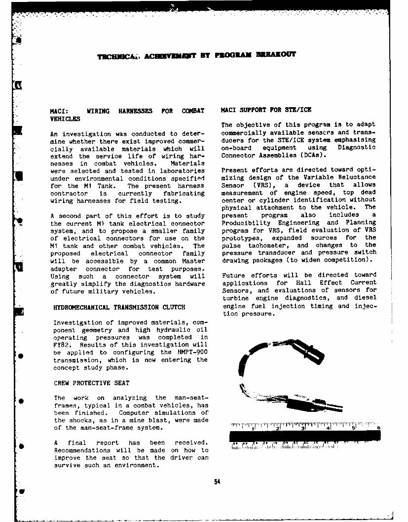
TSCEMUC&, ACEU~MW By PROGRA MRAKOUT
MACI: WIRING HARNESSES FOR COMBAT MACI SUPPORT FOR STE/ICEVEHICLES
The objective of this program is to adapt
An investigation was conducted to deter- commercially available senscrs and trans-
mine whether there exist improved commer- ducers for the STE/ICE system emphasising
cially available materials which will on-board equipment using Diagnostic
extend the service life of wiring har- Connector Assemblies (DCAs).nesses in combat vehicles. Materialswere selected and tested in laboratories Present efforts are directed toward opti-under environmental conditions specified mizing design of the Variable Reluctancefor the M1 Tank. The present harness Sensor (VRS), a device that allowscontractor is currently fabricating measurement of engine speed, top deadwiring harnesses for field testing. center or cylinder identification without
physical attachment to the vehicle. TheA second part of this effort is to study present program also includes athe current M1 tank electrical connector Producibility Engineering and Planningsystem, and to propose a smaller family program for VRS, field evaluation of VRSof electrical connectors for use on the prototypes, expanded sources for theM1 tank and other combat vehicles. The pulse tachometer, and changes to theproposed electrical connector family pressure transducer and pressure switchwill be accessible by a common Master drawing packages (to widen competition).adapter connector for test purposes.Using such a connector system will Future efforts will be directed towardgreatly simplify the diagnostics hardware applications for Hall Effect Currentof future military vehicles. Sensors, and evaluations of sensors for
turbine engine diagnostics, and diesel
SHYDROMECHANICAL TRANSMISSION CLUTCH engine fuel injection timing and injec-tion pressure.
Investigation of improved materials, com-ponent geometry and high hydraulic oiloperating pressures was completed inFY82. Results of this investigation willbe applied to configuring the HMPT-900transmission, which is now entering theconcept study phase.
CREW PROTECTIVE SEAT
The work on analyzing the man-seat-frames, typical in a combat vehicles, hasbeen finished. Computer simulations ofthe shocks, as in a mine blast, were madeof the man-seat-frame system. 2'I '"T"T'"II T"T ' 63 4 5
A final report has been received.Recommendations will be made on how toimprove the seat so that the driver cansurvive such an environment.
54
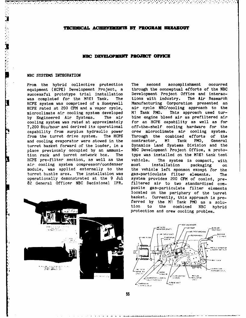
]P
-TBCHMCA ACl BY PROGRAM 331*1OW
NBC DEVELOPMENT PREWBCT OPFICEK.
NBC SYSTEMS INTEGRATION
From the hybrid collective protection The second accomplishment occurredequipment (HCPE) Development Project, a through the conceptual efforts of the NBCsuccessful prototype trial installation Development Project Office and interac-was completed for the MIEl Tank. The tions with industry. The Air ResearchHCPE system was comprised of a Honeywell Manufacturing Corporation presented anHCPE rated at 200 CFM and a vapor cycle, air cycle NBC/cooling approach to themicroclimate air cooling system developed M1 Tank PMO. This approach used tur-by Engineered Air Systems. The air bine engine bleed air as prefiltered aircooling system was rated at approximately for an HCPE capability as well as for7,200 Btu/hour and derived its operational off-the-shelf cooling hardware for thecapability from surplus hydraulic power crew microclimate air cooling system.from the turret drive system. The HCPE Through the combined efforts of theand cooling evaporator were stowed in the contractor, M1 Tank PMO, Generalturret basket forward of the loader, in a Dynamics Land Systems Division and theplace previously occupied by an ammuni- NBC Development Project Office, a proto-tion rack and turret network box. The type was installed on the MIEl tank testHCPE pre-filter section, as well as the vehicle. The system is compact, withair cooling system compressor/condenser most installation packaging onmodule, was applied externally to the the vehicle left sponson except for theturret bustle area. The installation was gas-particulate filter elements. Theoperationally demonstrated at the 9 Jul system provides 200 CFM of cooled, pre-82 General Officer NBC Decisional IPR. filtered air to two standardized com-
posite gas-particulate filter elementslocated on the periphery of the turretbasket. Currently, this approach is pre-ferred by the M1 Tank PMO as a solu-tion to the combined NBC hybridprotection and crew cooling problem.
HWA EXCMNGER
IF--AIR CYCLE MACHINEAIR MUTT DUJCT NL M SY SKIED AIR
C FILTER TEMPERATURE AIT
I o o CO0a-( Alll INLET
II ITI 1 .1 .A1
,~~~~~~~ {gl II -- sIIFAT , l
•~ II .IT1,!1
Wus
'..
TECHNICAL ACHIRVEMENJT BY PROGRAM BKRAKOUT
MATERIALS COMPATIBILITY WITH CHEMICAL NBC COOLINGWARFARE AGENTS
The NBC Development Project Office pre-The US Army Materials and Mechanics pared and submitted to higher headquar-Research Center has been funded over the ters a comprehensive plan for Developmentlast several years to conduct a program and Fielding of NBC/Cooling Systems foron the interaction of chemical agents Armored Vehicles. The plan required
, with non-metallic materials to guide the extensive coordination with the Mobilityselection of agent resistant materials Equipment R&D Command, Natick Labs andfor Army combat vehicle weapon systems. TRADOC, and involved an acceleratedSolubility and diffusiveness of chemical acquisition cycle. The plan offered aagents in selected materials are being strategy in streamlining typical acquisi-calculated from data obtained through tion cycles through the prequalificationtesting using chemical agent simulants. of a wide variety of cooling hardware and
" Solubility and diffusiveness of many driving mechanisms. The hardware availa-materials have been determined. Live bility and technical data packages willagent testing will be started in FY83 to allow vehicle PMOs to mix, match anddetermine if the simulant selections are select components best suited to the par-appropriate or if additional work to find ticular vehicle in question. NBC coolingnew simulants will be necessary. The end system type classification depends on the
. result will be information on test vehicle type classification. The planmaterials which will allow vehicle design has been approved by DARCOM and DA. Theengineers to choose or test materials qualification plan is planned to bewhich are resistant to chemical agents, instituted in FY83.yet are structurally acceptable andaffordable for weapon systems applica-tion.
Work on Chemical Agent Resistant Coatingsexploiting polyurethane paint as animpervious coating for combat vehicleexteriors has been successfullycompleted. Polyurethane paint conformingto MIL-C-46168B offers resistance to che-mical warfare agents as well as to decon-tamination solutions, particularly DS2.A special IPR recommended adoption ofpolyurethane paint as the preferred paintcoating in lieu of the alkyd paints
* currently applied. Work has been tran-sitioned from the R&D Center to TACOM.
56
0i
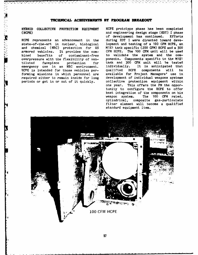
- . . , . . . .... , , , . . . • . . . . .
TECH-ICAL ACHIEVEMENS BY PROGRAM BREAKOVr
HYBRID COLLECTIVE PROTECTION EQUIPMENT HCPE prototype phase has been completed(HCPE) and engineering design stage (EDT) I phase
of development has continued. EffortsHCPE represents an advancement in the during EDT I were directed toward deve-state-of-the-art in nuclear, biological lopment and testing of a 100 CFM HCPE, anand chemical (NBC) protection for US MIEl tank specific (200 CFM) HCPE and a 300armored vehicles. It provides the com- CFM HCPE. The 100 CFM unit will be usedbined benefits of contaminant-free to validate the system and the com-overpressure with the flexibility of ven- ponents. Components specific to the MIEltilated facepiece protection for tank and 300 CFM unit will be testedemergency use in an NBC environment, individually. It is anticipated thatHCPE is intended for those vehicles per- qualified HCPE components will beforming missions in which personnel are available for Project Managers' use inrequired either to remain inside for long development of individual weapons systemsperiods or get in or out of it quickly. collective protection equipment within
one year. This offers the PM the oppor-tunity to configure the HCPE to offerbest integration of the components on hisweapon system. The 100 CFM rated,cylindrical, composite gas-particulatefilter element will become a qualified
standard equipment item.
57
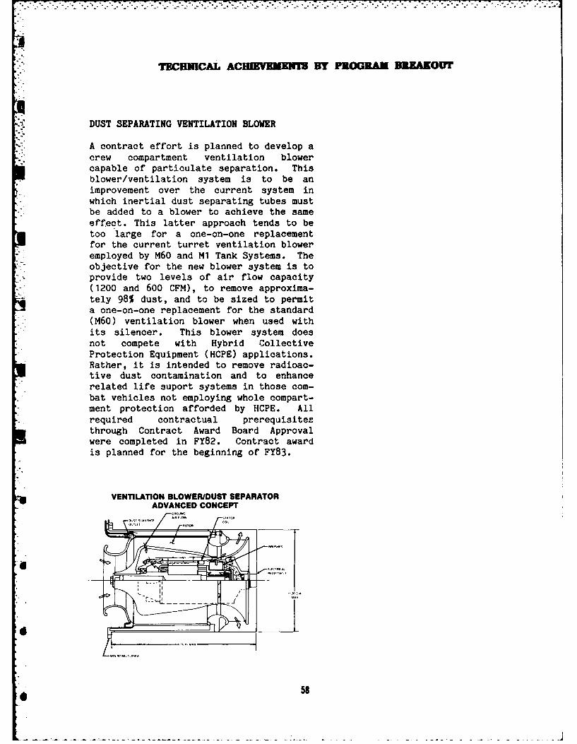
TECHNICAL ACHEVEMNSM BY PROGAM BREAKOUT
DUST SEPARATING VENTILATION BLOWER
A contract effort is planned to develop acrew compartment ventilation blowercapable of particulate separation. Thisblower/ventilation system is to be animprovement over the current system inwhich inertial dust separating tubes mustbe added to a blower to achieve the sameeffect. This latter approach tends to betoo large for a one-on-one replacementfor the current turret ventilation bloweremployed by M60 and M1 Tank Systems. The
- objective for the new blower system is toprovide two levels of air flow capacity(1200 and 600 CFM), to remove approxima-tely 98% dust, and to be sized to permita one-on-one replacement for the standard(M60) ventilation blower when used withits silencer. This blower system doesnot compete with Hybrid CollectiveProtection Equipment (HCPE) applications.Rather, it is intended to remove radioac-tive dust contamination and to enhancerelated life suport systems in those com-bat vehicles not employing whole compart-ment protection afforded by HCPE. Allrequired contractual prerequisitesthrough Contract Award Board Approvalwere completed in FY82. Contract awardis planned for the beginning of FY83.
VENTILATION BLOWERIDUST SEPARATORADVANCED CONCEPT
58
• o"-
-EUC A3BM D Y PROGRAM DIK
I UGIS ERING SUPPORT DEE RB RATZ
SURROGATE RESEARCH VEHICLE (SRV) OTHER MAJOR ACTIVITIES
The SRV is a test bed designed and being The Engineering Support Directorate wasfabricated in-house to evaluate various involved in studies to modernize in-house
*combinations of crew positions design, fabrication and test supportwithin new generations of main battle facilities and equipment. Computer Aidedtanks. The test bed design has bn'en Design equipment has been installed.
*translated into hardware using an M1 Initial training of personnel was*chassis/hull. The SRV will have provi- accomplished. An increase in the Special
sion for seating the entire crew in the Purpose Equipment funding enabled pro-hull or for checking combinations of curement of some new equipment to replacehull/turret seating. Design and fabrica- obsolete items.tion will be completed during FY83.
Efforts were expended supporting the*LIGHTWEIGHT TOW BAR (LTB) following projects:
*Lightweight combat vehicle tow bars o Design of a Battlefield Expedient*designed to ease crew handling have been Repair Kit
designed, fabricated and tested.*Stability problems, encountered during o Active Track Tensioner
initial LTB testing, have been corrected.The new design for the steel tow bar has o Fatigue Testing of T142 Track Pins
* resulted in less costly, lighter/strongertow bars, weighing 53 lbs. each, that can o Experimental Cone Brake Drum Testingbe easily stowed aboard tanks.
0 Track Pad Test Machine -
LVTP-12 ENGINE DEMONSTRATOR Designed/Fabricated
The power train of a Marine Corps LVTP-12 o Foreign Vehicle Activity, e.g., T-624landing craft has been changed to Grille repair; hull repairs on a Polish
allow incorporation of an RC-2-3502 ML arerotary engine. The vehicle, in the
* fabrication shop, was machined for theoM/3Want Crg Htcinstallation. The project can be o Smltr(hkr etn:HMGcompleted during FY83 if funding is OeEt SMAOR ( Srenttd o NBC -Vehicle Leakage Unit
" Metrication
o Fire Suppression Testing - FixtureDesign/Fabrication
59
4 ihnnwgnrtoso anbtl fclte n qimn.Cmue ie
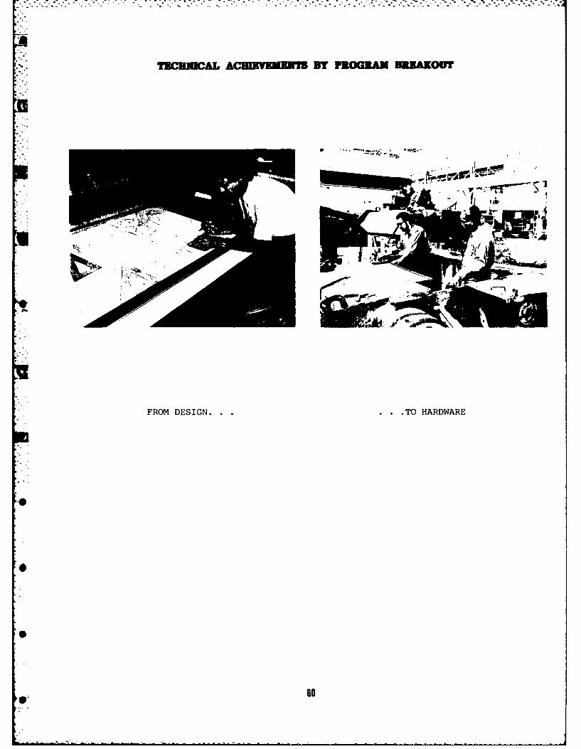
rbcwucL AHIKKUEISBY PROGRAM DIRIAKOUT
FROM DESIGN . . . . . . TO HARDWARE
06
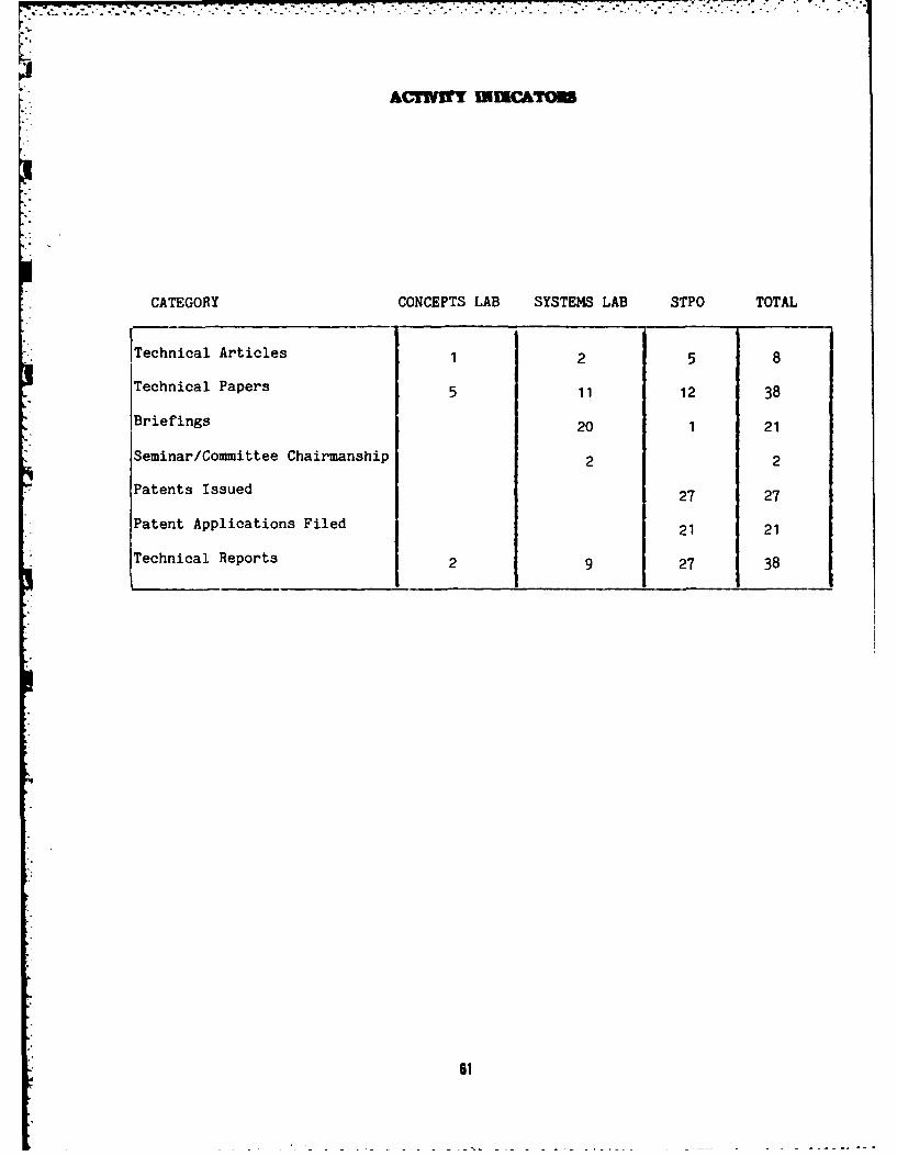
~~~~~~~~~~~.......... .. ......... .-. ... o~'.. . . .....- . . .,'- . -/
A&'rmry uxc&'rom
CATEGORY CONCEPTS LAB SYSTEMS LAB STPO TOTAL
ITechnical Articles 1 2 5 8
Technical Papers 5 11 12 38
Briefings 20 1 21
Seminar/Committee Chairmanship 2 2
, Patents Issued 27 27
Patent Applications Filed 21 21
Technical Reports 2 9 27 38
61
FACEUIrII
OVERVIEW P3.OIULUON SYSTEM LAB
The U.S. Army Tank-Automotive Command's Present facilities include nine test cells: two- R&D Center Laboratories and shops are are transmission cells, one is a vehicle cell,
* . equipped to develop and support the military and six are for engines. One cell is equippedvehicle fleet. Research and study are with a semianechoic chamber. Cell 9 isperformed here on propulsion systems, surface equipped to test tracked and w ,eeled vehiclesmobility systems, vehicular components, and at temperatures up to 160 F, for solarmaterials, from concept through prototype. radiation simulation and wind speeds up to 20-
MPH.The increasing need for the modernization oftest facilities and experimental fabricationmachine tools has resulted in the decision toprepare an updated master plan for a 5- to 10- TRACK AND wIPANSWIN LAByear modernization effort. This plan, whichincludes funding alternatives, will require One of the outstanding features of thisexpenditures of more than $5 million per year. laboratory is its dynamic simulation
capability. Vibration and shock inputs fromterrain tapes are fed through hydraulicactuators to the tires, wheel spindles or
.- PHYCAL SCIENCE LAB roadwheel arms. The simulation approachespermit accelerated testing of vehicles and
The laboratory has facilities for extensive components so that designs can be optimizedinvestigations into vehicle signatures and without time-consuming field testing. Smallersignature reduction methods. Non-destructive actuators accommodate fatigue tests ontest capabilities include holographic analysis. components and subsystems.Mini-computers and remote terminals providea ready capability for engineering analysis,modeling, and simulation studies. Automatedword processing equipment provides the EXPERIMENTAL FABRICATIONcapability to readily retrieve stored technicalsource and technical report data. This facility includes sheet metal, welding and
machining equipment capable of fabricatingKEWEENAW FIELD STATIO.N steel or aluminum hulls and turrets. The
assembly area has high bays and heavy-dutyThe Keweenaw Field Station located at cranes to handle vehicles up to 60-tons. TheHoughton, MI, is managed by the Keweenaw experimental foundry model and pattern shop,Research Center at the Michigan heat treating, plating and painting equipmentTechnological University. It consists of complete the fabrication complex.vehicle maintenance shops, small machineshop storage and office buildings. It houses ELECTRO-MCHANICAL SYSTEMSmany types of support vehicles and equipment.A wide variety of R&D work, along with Additional facilities permit testing of enginerelated field testing in support of TACOM's accessories such as tank air cleaners,mission, is performed there. electrical equipment components, and
mechanical and hydraulic subsystems.
62
FACHIl
.O
Edited and coordinated by:GLENN S. FINLEY, Technical Editor andProject Officer for the Posture Report
Suggestions to improve this report arewelcome. Request for Copies may beaddressed to the US Army Tank-AutomotiveCommand, ATTN: DRSTA-TS, Warren, MI48090
63
6-+