Embed Size (px)
Citation preview
Proceedings World Geothermal Congress 2010 Bali, Indonesia, 25-29 April 2010
1
Repowering Steamboat 2 and 3 Plants with New Axial Flow Turbines
Tom Buchanan, Wade Posten, Sean Berryman
Ormat Nevada, Inc., 6225 Neil Road, Reno, Nevada, USA 89509
Keywords: Repowering, Ormat, turbo-expander, Organic Rankine Cycle, Isobutane, Management of Change, Process safety Management
ABSTRACT
The Steamboat 2 and 3 geothermal power plants owned and Operated by Ormat Nevada, Inc. included four radial flow turbo-expanders originally supplied by a third party vendor with the original plant design. The turbo-expanders have experienced significant maintenance costs and unscheduled down time during the period 2006 through early 2008. The Ormat Technologies group undertook to repower the Steamboat 2 and 3 plants by replacing the four turbo-expanders with axial flow Ormat engineered turbines. The plant repowering was completed in mid 2008. The repowering was successfully performed with minimal plant down time using cross-functioning teams. The project required coordinated planning utilizing expertise from all aspects of a multifunctional team including engineering, manufacturing, construction and operation. Plant performance and reliability has been greatly improved. In addition to improved performance and reliability, on going maintenance costs are expected to be significantly less than with the turbo-expanders due to elimination of intermediate speed reduction gear boxes and complicated lubrication and shaft sealing systems.
1. INTRODUCTION
1.1 Plant and process description
Ormat Nevada, Inc acquired the Steamboat 2 and 3 power plants in February, 2004. The two plants are located within the Steamboat geothermal complex located approximately 9.5 miles south of Reno, NV just off US 395 South. The two plants were engineered and constructed by third party suppliers for Steamboat Development Corporation and were brought on-line in November and December of 1992.
The two plants are identical and share common power distribution, DCS and supervisory control. Depending on well field configuration the two plants are fed geothermal brine from approximately eight pumped production wells through a common brine gathering system. The two plants are fed brine in parallel. Upon exiting the plant, the geothermal fluid is re-injected into the resource through a distribution system and multiple injection wells.
The generation plants are based on the binary process and use geothermal fluid in liquid phase throughout the process. In each plant, brine is directed through a series of six shell and tube heat exchangers where heat is transferred from the brine to the working fluid. Both plants utilize iso-butane as the working fluid in the organic Rankine cycle process.
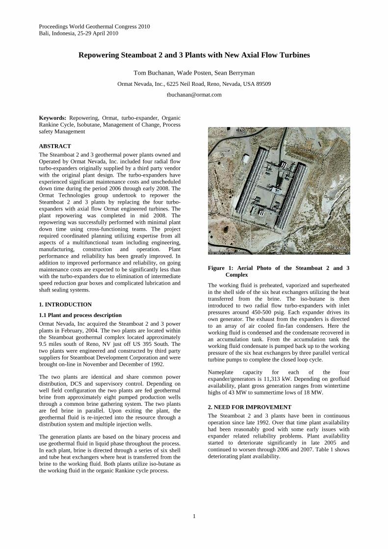
Figure 1: Aerial Photo of the Steamboat 2 and 3 Complex
The working fluid is preheated, vaporized and superheated in the shell side of the six heat exchangers utilizing the heat transferred from the brine. The iso-butane is then introduced to two radial flow turbo-expanders with inlet pressures around 450-500 psig. Each expander drives its own generator. The exhaust from the expanders is directed to an array of air cooled fin-fan condensers. Here the working fluid is condensed and the condensate recovered in an accumulation tank. From the accumulation tank the working fluid condensate is pumped back up to the working pressure of the six heat exchangers by three parallel vertical turbine pumps to complete the closed loop cycle.
Nameplate capacity for each of the four expander/generators is 11,313 kW. Depending on geofluid availability, plant gross generation ranges from wintertime highs of 43 MW to summertime lows of 18 MW.
2. NEED FOR IMPROVEMENT
The Steamboat 2 and 3 plants have been in continuous operation since late 1992. Over that time plant availability had been reasonably good with some early issues with expander related reliability problems. Plant availability started to deteriorate significantly in late 2005 and continued to worsen through 2006 and 2007. Table 1 shows deteriorating plant availability.

Buchanan, Posten, Berryman
2
Table 1.
Summary of SB 2/3 Availability Availability = Hours on-line/calendar Hours % of capacity is lower since many hours the units operated at less than full load due to temporary turbine repairs that would not sustain full load. Turbine 2004 2005 2006 2007 2008 2009
201 99.57% 99.62% 38.54% 86.91% 86.17% 99.90% 202 98.79% 90.70% 96.71% 43.42% 55.30% 100.00%
SB2 Average 99.18% 95.16% 67.62% 65.17% 70.73% 99.95%
301 99.74% 97.47% 95.74% 98.41% 75.51% 100.00% 302 97.57% 98.93% 96.24% 60.57% 85.00% 100.00%
SB3 Average 98.66% 98.20% 95.99% 79.49% 80.25% 100.00% Total SB 2/3 Average 98.92% 96.68% 81.81% 72.33% 75.49% 99.98%
A review of the causes of downtime clearly identified the majority of the down time was related to three major areas; 1.) Expander failures along with failures associated with expander auxiliary systems such as expander seals and lube oil systems, 2.) Contamination in the working fluid that was clogging system filters and strainers, 3.) General wear and tear on heat exchangers, pumps, auxiliary systems and instrumentation and controls.
2.1 Radial Flow Expander History
Early in the life of the facilities high vibrations and ultimately some wheel failures were experienced on three of the four expanders. In 1993 several wheel material configurations were utilized including aluminum alloys and titanium in an effort to minimize failures. The failures had been suspected to be caused by resonance and or fatigue issues. As a result of this early work most of the expander wheels were constructed of forged titanium.
Over the subsequent years of operation these expander configurations seemed to function reasonably well with only an occasional wheel blade issue. Then in 2002 two additional wheel failures were addressed with replacement wheels in plant stock. 2003 had one additional wheel replacement. Starting in mid 2005 expander 202 experienced several outages due to high vibrations. During these periods the plant stock of replacement or repaired wheels had been mostly exhausted and quotations for replacements solicited. Replacement quotes had revealed very long lead times and significant cost increases attributed primarily due to low availability of the forged titanium raw materials.
In early 2006 expander 201 experienced a wheel failure, plant stock had been exhausted and delivery times for new wheels were at least 12 months out. Over most of 2006 efforts were made to salvage the best of the failed wheels by trim balancing them in an effort to keep the plant at reasonable generation capacity. Expander 201 experienced repeated outages during 2006 attributed to the use of the trimmed wheel. It was clear that a long term solution was needed to either find alternative wheel replacements for the turbo-expanders or replace the expanders in their entirety.
In early 2007 expander 201 was down again with wheel failure and expander 202 experienced a catastrophic wheel failure that also caused catastrophic failure of the shaft seal and lube oil system, rupturing the lube oil reservoir tank. Throughout 2007 and early 2008 various replacement wheels are installed with varying success and still significant down time.
2.2 Working Fluid Contamination
The Steamboat 2 and 3 plants utilize isobutane as the working fluid. Isobutane is a common hydrocarbon and under normal operating conditions is non-corrosive to carbon steel and does not easily breakdown. Over the life of the plant operations several contaminants of the working fluid have been identified and are either introduced as materials of construction or inleakage into the system over time.
In the case of the Steamboat 2 and 3 plants, contamination in the form of fiberglass fibers in the working fluid was identified and showed up in the turbine inlet strainers and cycle pump inlet strainers. This was identified in 1993 and 1994. The original plant design included a noise abatement silencer in the exhaust of the expanders. The silencer design incorporated sound attenuation chambers packed with fiberglass and retained with perforated plate. Turbulence in the exhaust stream caused the fiberglass to pass through the perforated plate and into the process stream. This fiberglass was distributed throughout the process piping and eventually showed up in the strainers in the system causing high pressure drops if not removed on a regular basis. Cleaning of the system strainers required shut down and evacuation of the section of piping where the strainers are located. In the case of expander strainers, the expander would have to be taken off-line. In the case of cycle pump strainers, only one of the three pumps in each plant had duplex strainers, the other pumps had to be taken off-line while the strainers were isolated, evacuated and cleaned by hand. Due to the piping arrangement between the accumulator tank and the cycle pumps, debris tended to clog one pump inlet more than the other two.
Lubricating oil has also been identified as a contaminant in the working fluid. Over the life of plant operations small amounts of lubrication oils are passed through seals into the system. In some cases such as failure of the expander seal, large quantities of lube oil was introduced into the process stream. Over time the accumulation of oil contamination would settle in low points and also cause fouling on heat exchanger surfaces both in the air cooled condenser tubes and brine heat exchangers.
Water has been identified as a working fluid contaminant. Water can be introduced into the system from occasional tube leaks in the brine heat exchangers, a minor contaminant in purchased working fluid and as humidity in ambient air that may enter the system. Water contamination can contribute and promote corrosion in the carbon steel components of the process. In addition water can

Buchanan, Posten, Berryman
3
accumulate in low points or piping dead legs and present a freeze potential in cold climates during shut downs.
Non-condensable gases (NCG) can also be found as working fluid contaminants. These gases can be introduced into the process during tube leaks in the brine heat exchangers if the geothermal brine contains dissolved gases. Gases from the brine are typically carbon dioxide and hydrogen sulfide. Air can be introduced into the system during maintenance operations and may stay in the system if not evacuated prior to returning the system to service. Small quantities of these gases and water vapor can contribute to internal corrosion of the carbon steel components and piping throughout the process.
Through the period 2006-2008 the plants struggled with contaminants in the process in the form of products of corrosion, water and fiberglass. These contaminants clogged filters which required equipment shut down and manual cleaning on an almost weekly basis. In addition during winter months, water in the system presented freezing problems when the system was off-line. During the winter of 2007-2008 the freezing water and rust was especially troublesome.
2.3 General Wear and Tear
The Steamboat 2 and 3 plants had been operating continuously for close to 15 years and general wear and tear was making reliable operation increasingly difficult. The working fluid contaminants had made their way through out the process including the auxiliary systems such as vent gas compressors, evacuation skid and NCG removal system. Many mechanical systems such as vacuum pumps, gas compressors, relief valves, instruments and controls had been repaired and rebuilt over the years as normal maintenance items. Although many rebuilds had been performed correctly over the years, on some equipment it was just no longer possible to maintain original tolerances and rebuilt systems just did not last as long. Heat exchangers and air cooled condensers had been through many thermal cycles. The brine would deposit small amounts of scale in the heat exchanger tubes at the cold end of the passes. The two heat exchangers in each plant at the cold end of the passes had been cleaned on regular intervals, the second set of heat exchanger had been inspected but cleaning was minimal and none of the heat exchangers had been cleaned on the shell side. In general, contamination, wear and tear, thermal stresses and fifteen years of continuous operation had degraded the original plant availability and reliability.
3. SOLUTION
3.1 Short Term
With the failure of expander 201 early in 2006, it was clear that replacement wheels would be almost impossible to obtain from the original manufacturer or other after market suppliers. The biggest challenge was that the most successful wheels had been machined from forged titanium alloy and the supply market for forged titanium alloy had become extremely tight. The immediate and only solution was to try to take failed wheels with the least defects and trim and balance them and return them to service. Photo 2 shows a typical failed wheel and Photo 3 shows a wheel trimmed to run as a temporary solution.
Photo 2: Failed Wheel
Photo 3: Trimmed Wheel
A technical solution for the replacement expander wheels needed to be obtained. Fortunately, Ormat is fundamentally a technology company and has a broad range of technical expertise in the organization. The task was assigned to Ormat Systems Limited (OSL) based in Yavne, Israel to identify alternative raw materials, reverse engineer the wheels, procurement and manufacturing. OSL developed a plan to engineer several replacement wheels from aluminum alloy which was more readily available than the titanium. The procurement and engineering effort for the titanium alloy wheels would continue in parallel. In the end, OSL supplied three aluminum wheels and two titanium wheels for installation over the period of late 2006 to early 2008. During this period the Ormat Nevada Operations group and the OSL team maintained a constant dialog on wheel performance and improvements. Although a solution for replacement expander wheels had been obtained, overall plant availability continued to be unacceptable.
3.2 Long Term
By early 2007 it was clear that in order to regain significant improvement in overall plant availability for the next 10 to 15 years, a major repowering effort would be needed to address all of the identified performance issues. The primary focus of the repowering effort would be upgrade or replacement of the turbo-expanders. The decision to undergo a major plant repowering effort was made. The next step in the project was to clearly define the scope of work to meet the objective of a highly reliable facility for at least the next 10-15 years.

Buchanan, Posten, Berryman
4
The first priority of the project scope was replacement of the expanders.
Ormat Technologies Inc. is a vertically integrated technology based company with business units that are capable of engineering, manufacturing, constructing and owning and operating geothermal power plants. Ormat has been a pioneer in organic Rankine Cycle (ORC) power plants for use in geothermal and heat recovery applications. Ormat markets the Ormat Energy Converter (OEC) which is a complete ORC power cycle including Ormat proprietary axial flow turbines. So it was a natural progression to evaluate replacement of the turbo-expander units with Ormat designed turbines.
Several key differences between these two types of expanders needed to be evaluated for the final
determination. The following table identifies some of the differences between these two systems.
Photos 4 and 5 show the turbo-expander arrangement with gearbox and oil and degass systems
Due to the high speed of the turbo-expander unit, the external gear box and specialized seal and lubrication systems add significant complexity to the expander with many parts and instruments requiring on-going preventive maintenance. This was a significant factor in the comparison of the two options.
Based on the rugged simplicity of the Ormat turbine design, cost, availability, demonstrated reliability and experience Ormat chose to replace the turbo-expander units with Ormat turbines.
Table 2.
Ormat Turbines Turbo-expander Type Axial Flow, multi-stage
turbine Radial Flow, single stage turbine
Rotor Speed (rpm)
1,800 9,000
Speed Reduction Gear
NA External 5:1 reduction ratio
Bearing Elements
Rolling element, spherical roller
Fluid-Film, journal and thrust, thrust balancing system
Shaft Seal Double-mechanical with barrier fluid, external pump, circulating oil, air cooling and filtration
Labyrinth with leaking gas purge 1.
Lubrication System
External pump, circulating oil, air cooling and filtration. Lube oil and seal oil capacity approximately [100] gallons.
External pump, circulating oil, heating, degassing, air cooling and filtration, lubrication oil is shared with the turbine rotor and reduction gear box. Oil capacity approximately 2,000 gallons.
Rated Maximum Power (kW)
11,300 11,948
Efficiency at Design Point (%)
86 87
1. The turbo-expander unit is a relatively high speed machine. The shaft seal system incorporates a labyrinth seal designed to allow some of the working fluid gases to pass to the bearing side to prevent oil from passing into the process. This gas leakage combines with the lubrication oil as it exits the rotor housing. In order to separate this gas and return it to the process the mixture is heated
and sent to a degassing tank where the isobutene can evaporate. Recovered oil is returned to the oil reservoir tank and the separated isobutene vapors are sent to a gas recovery compressor and eventually to the plant air cooled condensers.
Generator Gearbox Expander
Photo 4: Turbo-expander Unit
Oil cooler
Generator Lube oil and degass systems
Photo 5: Turbo-expander Unit

Buchanan, Posten, Berryman
5
Since the Steamboat 2 and 3 plants were originally designed to utilize isobutane as the working fluid and the existing heat exchangers and balance of plant systems would stay in place, the new turbines would be designed and optimized to work with isobutane. Ormat has a track record of designing and installing expansion turbines utilizing a variety of working fluids, process conditions and sizes from a few kilowatts to tens of megawatts. This experience allowed turbines to be designed and optimized for this specific application and working fluid. The design includes a low speed 1,800 rpm turbine, eliminating the speed reduction gearbox, standard materials of construction, standard bearing and seal components and much simplified lube oil and seal oil auxiliary systems. The design also eliminated the need for the complicated lube oil degasification and recovery systems.
Photos 6 and 7 show the Ormat Turbine retrofit without gearbox and with new lube and seal oil skid.
Generator Lube and Seal Oil Skid
Ormat Turbine
Photo 6: Ormat Unit
Ormat Turbine
Generator
Photo 7: Ormat Unit
4. OVERALL PROJECT SCOPE
In addition to replacement of the expanders there were many other key pieces of equipment and systems that needed to be included in the scope of work to get a complete project. There would be several working groups involved with the project so it was important to clearly identify the project scope and responsibilities. Although Ormat is unique in having all of the various disciplines in-house, clear definition of project scope is even more critical for projects involving outside resources. A clear definition of scope and design basis is also an integral part of the Management of Change (MOC) procedures utilized by the Steamboat Complex as part of their Process Safety
Management (PSM). In order to incorporate all of these elements into one document a Project Agreement was drafted to include the following outline:
A. General Description of the Project
B. Design Criteria and Conditions
C. Detailed Scope of work
D. Functional Group Responsibilities
E. Changes
F. Commissioning, Testing and Take-Over
G. Schedules:
• Schedule A- Project milestones.
• Schedule B - Testing Procedures.
A list of some of the key scope activities and responsibilities included:
Products Group
• Thermodynamic design and review
• Turbine and turbine auxiliaries design and manufacture
• Turbine controls and coordination with existing ABB Bailey DCS
Projects Group
• Safety – Coordination of Contractors with site safety plan and procedures
• Project budget and schedule – develop and manage overall project schedule and budget
• Removal of old expanders and auxiliaries
• Mechanical and electrical installation of new turbines, controls and interconnecting piping
• Start up and commissioning of new turbines and controls
Operations Group
• Safety – Overall site safety coordination
• Management of Change – Manage and document change process
• Securing the Process – Isolate, evacuate and store working fluid inventory, system de-energizing, work permits
• Heat exchangers – open, clean tube side and shell side, perform non-destructive testing (NDT), repair leaks and defects.
Buchanan, Posten, Berryman
6
• Air cooled condensers – Random inspection, open, clean, perform NDT, repair as required.
• Cycle pump strainers – install duplex strainers or filters for on line cleaning
• Support coordination of new turbine controls with legacy Bailey DCS
• Generators – Clean, inspect, repair as required
• Accumulator vessel – open, clean, inspect, repair as required
• Piping – Random NDT inspection, repair as required
• Valves – Inspect, clean, repair or replace as required
• Pressure Relief Systems – Validate sizing basis, clean, inspect, repair or replace as required, recertify
• Utility Systems – Evacuation Skid, NCG Removal Skid, Vent Gas Compressors, Compressed air, clean, inspect repair or remove from service as required
5. PROJECT IMPLEMENTATION
Each functional group assembled schedules and budgets for their scope of work. These were then combined into an overall Project Task.
The Products Group defined a schedule to deliver turbines, turbine auxiliaries, piping, electrical components and controls in about 7 ½ months.
The Projects Group defined a schedule for shut down, tear out of old equipment and installation of new equipment over a period of about 4 months. The plant outage schedule required shut down of Steamboat 3 for two months and after it was commissioned Steamboat 2 would be shut down for two months.
The Operations Group defined a schedule for the balance of plant (BOP) items to coordinate with the Projects Group outage schedule.
Actual plant outage for Steamboat 3 was close to the two month target. Actual plant outage for Steamboat 2 was just over one month. The improvement in outage schedule for Steamboat 2 was a result of applying lessons learned from the Steamboat 3 outage.
The Projects Group provided all coordination with the Products Group and local contractors for the new equipment delivery and installation.
The Operations Group and Projects Group identified a primary contact for coordination of all on site activities. These two project coordinators arranged coordination and safety meetings. Prior to construction the coordination meetings were scheduled monthly. Once the first plant was shut down and construction started, the meetings were scheduled weekly and during peak construction periods and commissioning the meetings were held daily. These meetings proved very valuable in managing safety and coordinating the many activities being conducted on a site
with multiple sub-contractors, construction and on-going plant operations.
The overall repower project for Steamboat 2 and 3 from construction to full commissioning was completed almost one month ahead of schedule. Tear out and installation by the Projects group went very smooth and resulted in a very clean and straightforward installation.
Upon substantial mechanical completion of the two turbines in each plant and after completion of electrical testing and control system loop checks, a pre-start up safety review (PSSR) was conducted to insure all components and systems had been installed and tested according to design and all safety systems were in place and functional. Completion of the PSSR was the final release to allow the process to be recharged with the working fluid, isobutane.
During the cleaning and inspection of the BOP equipment it was normal to find a few unexpected conditions that would need additional repairs or replacements. This was definitely the case in regards to the four generators which were to be cleaned and inspected. The scope had called for the generators to be cleaned and inspected on site. The first generator opened was found to have rotor damage and would need to be pulled from the site and sent to the shop for a more thorough repair. Pulling the generator and sending it to a qualified repair shop while the rest of the mechanical works proceeded on site turned out to be a better solution than on site inspections. This was carried over to the remaining three generators, with all being pulled and shipped off site for complete inspection and overhaul.
Another area that introduced unexpected conditions was the cleaning and inspection of the air cooled condensers, heat exchangers and accumulator tank. Operating problems with contaminants in the working fluid had indicated a cleaning of these components was critical to long term reliable operation once the new turbines were installed. Fortunately, the initial inspections determined that the condensers, heat exchanger tubes and accumulator tank all were within the allowable corrosion allowance and significant replacements would not be required. The scope called for a chemical cleaning of the shell side of the heat exchangers and accumulator tank since entry into these locations was either not possible or undesirable. The cleaning called for three washes including a caustic wash to break down and remove oil residues, an acid wash to remove products of corrosion and finally a passivation wash to protect the equipment until filled with working fluid. Although setting up the equipment and temporary piping for the chemical washing presented some logistical difficulties, the cleaning was successful and went relatively smooth. The biggest unexpected factor was disposal of the spent cleaning fluids. The original proposed method of disposal was ruled out after review by local regulators. In the end these fluids had to be transported off site to authorized disposal facilities for proper handling and disposal.
During the project design phase there was some concern on integrating the new turbine controls with the existing Bailey DCS system. A review by the Ormat controls engineers identified that the existing expander controls were mostly independent from the BOP controls with only a few interface points. The new turbine controls would be handled by a new PLC based system that would interface with the Bailey DCS at the essential points. During commissioning the commissioning team verified all interfaces and completed the integration. Start up of the new turbines was completed with very few controls or tuning issues. After all
Buchanan, Posten, Berryman
7
systems were verified, actual turbine start up from first rolling to synchronization was usually a one day process. All turbines were run up to full power during commissioning with no issues.
Since start up of the last new turbine in late September, 2008 until the writing of this report there has been no unscheduled down time associated with the new turbines or turbine auxiliaries.
6. CONCLUSIONS AND OBSERVATIONS:
The repowering of the Steamboat 2 and 3 plants successfully replaced four aging and unreliable radial flow expanders with new highly reliable axial flow turbines. In addition the balance of plant components were cleaned, inspected and repaired to insure the plants would continue to perform with high reliability well into the future.
The project was completed almost one month ahead of the original schedule and continues to operate at full capacity.
A major repowering of existing and aging power plants is a significant undertaking and requires special planning and attention since it involves down time and significant lost revenues if not completed timely. There is always some element of the unknown and unexpected equipment issues that cannot be identified until the plant is shut down and equipment opened for inspection.
Some of the elements required for a successful repower project include:
• Develop a clear and concise project scope with clearly identified responsibilities. It is easy during the course of a project to get side tracked or expand the scope of the project. The team needs to stay focused and on task.
• Assemble a qualified and experienced team. A team for a major repowering needs to include process
design, flexible and responsive equipment suppliers, competent construction and installation experts, operational experience and focused oversight.
• Safety must be a high priority especially during a project where operations and construction are continuing on the same site. A project such as this introduces unusual operating conditions as well as coordination of a lot of people working in a small area and in unusual conditions.
• Environmental a regulatory review needs to be involved early and continuously to assure all possible consequences and impacts are identified and planned for.
• Communication is critical. Maintaining good, open and consistent communication throughout the project and with all parties can minimize confusion, conflict and allow quick resolution of unexpected issues as they arise.
• Coordination is also a key to success. Identifying individuals as the primary point of contact for each functional group helps keep communications focused and flowing.
Ormat is fortunate and unique in the geothermal industry to be fully vertically integrated. With expertise from exploration and development to plant design, construction and operational experience, complicated projects such as existing plant repowering can be accomplished quickly and efficiently.
REFERENCES:
Instruction Manual, Turboexpander with Generator Load Designed and Manufactured for the Ben Holt Company for Installation at Steamboat Development Corp., Atlas Copco, Rotoflow Corporation, Inc., July 1992.