Embed Size (px)
Citation preview

This Document
Reproduced From.,
Best Available Copy
II
"EVAPORATION LOSSES RESULTING FROM
CAMOUFLAGE OF POL TANKS IN KOREA
K/) William)Hughes
DDC
a . . Y - - / /- -_. _Fn~ ! APR qT
P LJLPPlIuiE L" wL
HQ -PACIPIC AIR POROUS
•,j' ?J

SUMMARY
At the present time, POL tanks in Korea are painted white to mini-
mize evaporation losses. This makes them highly visible to potential
attacking aircraft. If the POL tanks are painted with a dull tonedown
color similar to that being accomplished for the remainder of the air
base facilities, there is the concern that evaporation losses might be
costly. This paper determines the cost of POL evaporation associated
with tonedown painting of tanks and explores several alternatives.
At Kunsan and Osan Air Bases, there are eight principal POL tanks
aboveground. If these tanks were painted with tonedown colors, total
evaporation loss cost for all of them together would increase by about
$2000 per year. Two alternatives that reduce the evaporation losses
even more and additionally provide concealment superior to tonedown
painting are burial and camouflage with netting. Either of these alter-
natives would reduce evaporation losses more than the $2000 per year;
but in neither case would this saving offset the increased installation
costs.
Since gasoline storage suffers nearly four times greater evaporation
losses, as compared with JP-4, the recommendation is made that gasoline
be stored underground whenever this option is available and tactical con-
siderations permit it. .Floating pans also reduce the evaporation losses
significantly; and even though not cost-effective to install on existino
tanks, priority should be given to storing gasoline in these tanks.
i!i

Several of PACAF present policies were affirmed in this study.
PACAF's full tank policy results in minimum evaporation loss. Con-
structing new tanks underground also results in minimum evaporation
loss.
ii

TABLE OF CONTENTS
Page
Summary .......... .......................... . i..
Background and Objective ....................... . l..
Methodology ........... ...................... . l.
Assumptions ............... ..................... 4
Data .............. ........................... 8
Calculations ............ ....................... 9
Discussion ............ ......................... 16
Conclusion ........... ........................ .. 26
Recommendations .......... ..................... .. 26
References .............. ........................ 28
Distribution ......................... 29
SkT•SSI e
V

Tables and Figures
Page
Figure 1, Adjustment Factor for Small Tanks ..... ........ 5
Figure 2, Breathing Loss from Fixed Roof Tanks .... ...... 6
Figure 3, Effect of Color on Evaporation Paint Factor . 8
Figure 4, Vapor Pressures 1 psi to 7 psi RVP ... ....... .10
Figure 5, Vapor Pressures 5 psi to 14 psi RVP .... ....... H1
Figure 6, Relation for Estimating Breathing Losses fromlanks Operating at Less Than the 2.5 psiPressure Vent Setting ...... .............. 13
Figure 7, Linear Extrapolation of Paint Factors for FreedRoof Tanks and for Floating Roof Tanks ... ..... 15
Figure 8, Working Loss from Fixed Roof Tanks .... ....... 24
Table 1, Fuel Characteristics ....... ............... 9
Table 2, True Vapor Pressures ....... ............... 9
Table 3, POL Breathing Losses from Fixed Roof Tankswithout Pressure Vents or Floating Pans ... ..... 12
Table 4, Annual Breathing Losses .... ............. ... 17
Table 5: Costs of Tank Installations in Korea .... ....... 19
iv

1. BACKGROUN]D AND OBJECTIVE, Pending 6!1 XOA study of tonedown effec-
tiveness ii Korea, HQ PAC,.F in May 1974 directed interim tonedown of USAF
facilities on Korean bases with "solid, dull/flat colors to match the
predominant seasonal color of the year." Implementation of the interim
tornedo'rn policy is to occur during the normal repainting cycle commencing
FY 76. Because of concern over possible increased evaporation losses from
darker colored tanks, hitherto painted white, the interim policy specifies
that camouflage nets, rather than tonedown paints, will be used for above-
ground POL tanks. The objective of this study was to determine if the cost
of POL evaporation resulting from use of darker paint on tanks is such as
to justify alternate camouflage methods (e.g., netting) from a strictly
economic standpoint. Considerations of increased camouflage effectiveness
which may be afforded by such alternate methods were not evaluated.
2. METHODOLOGY
a. This study relies primarily upon an internal publication by SOCAL
(formerly Standard Oil Company of California) entitled Evaporation Pre-
vention Manual (ref 1) which, in turn, is largely based upon several
American Petroleum Institute (API) evaporation loss bulletins, the most
pertinent of which is API Bulletin 2518: Evaporation Loss From Fixed-
Roof Tanks (ref 2). Three categories of evaporation losses are considered
in the manual: boiling losses; working losses; and breathinn losses.
Boiling losses are defined as evaporation losses resulting from heating
of the bulk liquid fuel to or above the temperature at which its vapor
pressure is equal to atmospheric pressure. Since this condition is diffi-
cult to achieve in other than rather small tanks and in vented pipelines
exposed to direct sun, it is not considered in this study. Working losses
k1

are defined as those evaporation losses resulting from emptying and filling
the tanks with consequent displacement of vapors into the atmosphere.
These are sometimes called filling losses. Since filling losses are en-
tirely a function of activity (i.e., use of POL), these losses are not
considered either.
b. There remains a category of loss known as breathing loss. This
type of loss results from changes in temperature of gases in the tank.
(There is also a small component of breathing caused by changes in atmos-
pheric pressure but breathing losses from this origin are negligible.)
When the temperatut* increases, as during the day, the gases warm and
flow out through the vent and, escaping into the atmosphere, are lost.
Then, when the temperature declines, as at night, outside air flows back
into the tank via the vent opening and mixes with the vapors inside the
tank. While devices* are used to reduce breathing losses, these losses re-
main principally dependent upon temperature changes experienced by the
gases inside the tank. These temperature changes arise from external
ambient temperature change and from solar heat flux absorbed by external
surfaces of the tank during the daytime. The temperature of the liquid
contents of the tank changes but slowly owing to its much greater thermal
inertia. In fact, the fuel acts in part to moderate the thermal effects
transmitted through the upper surfaces of the tank. The color of these
upper surfaces has a significant influence upon the amount of heat absorbed
from solar radiation: light colors reflect the heat while dark colors ab-
sorb it. It was for this reason that past practice has been to paint
the tanks white.
* Such devices include pressure vents, inlet baffles, vapor conservationdevices, floating roofs, and internal floating pans. All of the tanksconsidered have pressure vents and one has an internal floating pan.
2

c. The breathing loss (L) has been modeled (ref 2) by equation:
L = Kck a Db Hc Td F14.7-P]
where
L = annual loss, bbl/yr
P = true vapor pressure, psia
D = tank diameter, ft
H = mean height of roof above fluid level (headspace), ft
T = mean daily ambient temperature change, 'F
F = paint factor
Kc = fuel type adjustment factor
and
a,b,c,o,k = constants.
For determining the true vapor pressure P in cases where the mean fuel
bulk temperature is not known, ref 2 states that this temperature is to
be estimated by adding 5°F to the mean annual temperature. The mean daily
ambient temperature change T is found by subtracting the mean daily
temperature minimum from the mean daily temperature maximum. The paint
factor F and the fuel type adjustment factor Kc are determined from
field tests.
d. Ref 2 reports that this formula has been found to be reasonably
accurate over a sufficiently long period of time* for tanks of more than
30 feet in diameter. (For a smaller tank, a correction factor must be
" Iide divergences from the values predicted by this formula may be encoun-tered over short periods of time. Over the space of a year, however, losseshave been found to agree within ten percent.
3

applied. See Figure 1.) Values of 'Ie constants are given in ref 2 as
follows:
a = 0.68
b = 1.73
c = 0.51
d = 0.50
k = 0.024
Kc = 1.0 for gasoline; 0.58 for crude oil.
e. A nomogram has been developed by API to simplify breathing loss
calculations. A copy is appended hereto as Figure 2.
3. ASSUMPTIONS
a. It was assumed that camouflage paint has approximately the same
infra-red reflectance characteristics as the "dark medium grey" paint
which was evaluated in ref 2. This key assumption was considered reasonable
since the tonedown paint has been specified only as "solid dull/flat
colors." From Figure 3 it is seen that the paint factor could not increase
by more than about 75 percent from the "dark medium grey" even if black
paint were used. (See paragraph 6d).
b. In the absence of recorded data the annual mean fuel bulk tempera-
ture was considered to be 50F greater than the annual mean atmospheric
temperature. This is in accordance with the recommendations of ref 2.
c. Space above the fuel was assumed to average six feet. This assump-
tion was based upon the PACAF "full tank policy" as moderated by the re-
quirement to empty the tanks occasionally for maintenance and inspection.
Losses are not particularly sensitive to changes in headspace. For example,
the loss equation shows that increasing the mean headspace 100 percent
increases the losses only by 40 percent.
4

.80 /•-
.60_
"0 40
0 10 20 30
Tank Dameler in Feet
FI;G. U -AiIju•tlomciat Fucttor for Sm.al-i)nuii,'*Ler 'r
!:5

0., 1 Lk
-~0.
00M8
K Kir _0006*, 00
I I 0- 000
ooot ocp
E~: 1 1 ~i7Voco0 02 0
it 0001
-.- - -. 0009
~~ ~0011 c a
EI 0. 0C Oc
II - .~ 000C
009 L 0 -if- -0 II -0
I J 009Ii 00 00C
I~g 06_ i
Tu- _ ___ow iL 0
_________ OFt 0
L? L
6.

:::i l
.C....v,
...... ¶ . .... ...L~~iZU~- -! Z6.V, ††††
..... ... 1,,,...........
*......... .. .
I~~~~. .......Kv2 I : '
7, -t . .. . ... ..
........... .
. . . . . . . . . . ....... . .. 4....

d. Breathing losses from underground tanks were considered negli-
gible, as were losses from smaller tanks (5,000 bbl and below). This is
based upon the fact that underground and covered tanks are insulated from
ambient temperature changes and so are not subject to significant daily
breathing losses, while losses from smaller tanks are of considerably re-
duced significance when compared with losses from larger tanks as shown
by the adjustment factor for small tanks in Figure 1.
e. Pressure/vacuum vents are set to operate at plus 2 1/2 oz per
square inch pressure and minus 1/2 o2 per square inch vacuum. At these
settings the breathing losses are reduced by about 12 percent. (See
Figure 6.)
f. Delivered fuel prices were taken to be $15 per bbl (35.7€/gal) for
the purpose of cost estimates.
g. In the absence of data, the volatility of diesel fuel was assumed
similar to that of JP-4. This is because the Kc factor is reported in API
publications only for gasoline and crude oil; this necessitates assuming
JP-4 is more likely to have characteristics similar to crude oil rather
than to gasoline.
h. Tanks which are being phased out in the very near future (six
months) were not considered.
i. HQ PACAF (LGSF) values of Reid Vapor Pressures for the various fuels
were used. These values tended to be higher than SOCAL data which would
yield lower loss estimates.
4. DATA
a. Tanks. The 10,000 bbl tanks are approximately 55 feet in diameter.
The 55,000 bbl tank being installed at Kunsan is 93 feet in diameter.
b. Fuel. Physical characteristics of fuels are summarized in Table 1
as follows:
8

SLOPE OF ASTMTYPE FUEL REID-VAPOR PRESSURE EVAP CURVE AT 10% EVAP
JP-4 2.0 - 3.0 3.8
MG-I 7.0 - 9.0 2.5
115/145 7.5 - 8.0 2.7
DFM UNKNOWN UNKNOWN
Table 1. Fuei Characteristics
c. Climate.
(1) Annual mean daily temperature maxima are 61°F at Kunsan and
62 0 F at Osan.
(2) Annual mean daily temperature minima are 490 F at Kunsan and
44 0F at Osan.
(3) Annual mean windspeeds are 8.1 mph at Kunsan and 5.2 mph at
Osan.
5. CALCULATIONS
a. True Vapor Pressures (TVPs). Figures 4 and 5 are used to find the
true vapor pressures, which are shown in Table 2.
Mean Daily Calculated Fuel Reid '..' r Pressu-r!Slpce ofocation Tempratue_'F Temperature OF ASTM Ev&;) Curve at lO, Evap True Vapor Pressure
High Low (mean + 50 F) JP-4 , MG-1 ; 115/145[ "F JP-4 M.- 5/ 1 A5/14b 9FM
Kunsan 61 49 60 2.5 8.0 7.8 .:*[.j 1.1 4.0 3.9 .*(.1.,13.T :2.5 .7 -
, - -
Osan 62 44 58 2.5 8.0 7.8 2•t"I 1.05 31.8 3.7 3 ( .(0,,)
3.8 . 2.' l
• JP-4 data used for DFM
Table 2. True Vapor PreSLsui t.C
b. Breathing Losses. Once the TVPs have been found, Figure 2 may be
used to find breathing losses for fixed roof tanks without pressure vents
9

0.2
-0.3
120-
0.4
I10-
-0.5
0.6 S 10
- 3a, 0
0.7 43U,J
:) I
o 21<
n. w
0. 0. 9 -
- aD 0 <
Zt 6
S~~70--uw 3 cc:
V)a<
-" 60
o - -. z
0W
0l. -r
z6
-2.0 o0--
tt 40
<> 3.030-
S SLOPE OF THE ASTBN O DISTILLATION CURVE AT --S- IO1 PER CENT EVAPORATED=-
DEG F AT 15 PER CENT MINUS DEC. F AT 5 PER CENT 20"-'
4.0
- m THE ABSENCE OF DISTILLATION DATA THE FOLLOW- 10
ING AVERAGE VALUES OF S MAY BE USEDMOTOR GASOLINE 3
- 5.0 AVIATION GASOLINE z
LIGHT NAPHTHA (9-14 LB RVP) 3.0NAPHTHA (2-8 LB RVP) 2.5
-- 6.0
7.0
Y-'i(. If. -Vnlor [Prc.ssurrs o.f .a.olitirs aind Fini~shcd t',ltrolcmita I'rohuciLs- ! .hs to 7 I. ltVi'.
10

• -O.niO
-- 0.90
-- 1.00
120-
110-
I00
- .2.0
90-
-j m-J - 0 I0 -0n 1 80- Z,co 2 uj
- 3 c c-3.0 41 7 -
Ic - a! l --
- - 6 -z -- tL_707 0
LI aLni - -nLi
"aI.-19 -3
4. -4. 00 L
i/I A.-j40 0•I I (L
-6.0 Li
LiL
7.0- 30-1]- S =SLOPE OF THE ASTM DISTILLATION CURVE AT
10 PER CENT EVAPORATED
- 8.0 DEG F AT 15 PER CENT MINUS DEG F AT 5 PER CENT 20<. - 10
9.0- IN "THE ABSENCE OF DISTILLATION DATA 1HE FOLLOW-
cc ING AVERAGE VALUES OF S MAY BE USED)I- 10.0 MOTOR GASOLINE
3AVIATION GASOLINE
11.0 LIGHT NAPHTHA (9-14 L3 RV[') 3.5 0-NAPHTHA (2-8 LB RVP) 2.5
-12.0
-13.0
14.0
1:1i;. 5'•Valur IPresstireor. if ;nmliet neic athd 1hiis'v I'.irciletim= form~** I~ tor -s- L let1 .1) IVI'.

or floating pans. (The crude oil scale is used for JP-4 and diesel fuel,
per paragraph 3g supra.) Values for losses of several fuels from 10,000
bbl tanks (55 ft diameter) and 55,000 bbl tanks (93 ft diameter), both
painted white and toned down, are listed in Table 3.
Lossesi Losses'
Tank Outage (Ft) Mean Daily .of White i Tonedown White Tonedown
ocation (i.e. Headspace) Temp Change *F Fuel IVP F1.00 I Fb1.50 Fl./AD F-1.50
Kunsan 6 12 JP-4 1.1 25 35 60 90
MG-I 4.0 105 160 260 390
15/145 3.9 100 1 155 245 r 385
pfOM *(1.l) 25 35 60 , 90
Osrn 6 18 JP-. 1.05 31 45 105
MG-I 3.8 120 180 280 360175 7 355115/145 3.7 115 1 175 275 3
f.FM *(1.05) 31 I 45 70 105
J ,P-4 Data used for DFMTable 3. POL Breatl;ing Losses for
SFrom 55' die tanks (10,000 bbl) Fixee Roof Tari1;s WithoutPressure Vents or Floating
2 From 93' die tanks (55,000 bbl) Pans
c. Effects of Floating Pans. The 55,000 bbl tank is equipped with
a floating pan. The procedure for calculating breathing losses from tanks
with floating pans is given in reference 7. It is based upon the follow-
ing empirical formula:
Ly t1.5 [ P 0.7 Vw0 . 7 Ks Ke Kp
where:
Ly = evaporation loss -- bbl/yr
Kt = 0.045 to 0.14 depending upon tank type and seals. For welded
tanks, the lower value is used
D - tank diameter -- ft
12

--- -.- I ' .t l-
00 - f0_~j 0 -
I-I- i- II i iW 0 0
C 0 <0 4030Figre 6. lto 1o stmtn rahn
IL
setting.
• Tiscuveisfo moo ao ineol.I sssece htpesr
<0
QW
ow 20
0 10 2030440OPERATING PRESSURE RANGE, OZ/SQ IN.
Figure 6. Relation for Estimating BreathingLoss From Tanks Operating at LessThan the 2.5 psi pressure ventsetting.
*This curve is for motor gasoline only. It is suspected that pressurevents would be even more effective when used on tanks containing lower
vapor-pressure fuels such as JP-4 and diesel fuel.
13

P = true vapor pressure of fluid in tank -- psia
Vw = wean wind speed -- mph
Ks = seal factor= 1.00 for tight fitting seals= 1.33 for loose fitting seals
Kc = fuel type factor
= 1.00 for gasoline= 0.75 for crude oil
Kp = paint factor= 1.00 for light grey or aluminum= 0.90 for white
It is at once readily apparent that a wide range of values may be derived
from this equation, depending upon the values selected for the nwnerous
"constants." The paint factor to be used is obtained by extrapolation,
using figure 7, to obtain a value equivalent to the paint factors used
for fixed rcof tanks. Since it is contemplated that this tank will be
used for storage of JP-4, the true vapor pressure value used is P = 1.1 psia.
Thus the equation reduces to:Ly:K 915[ 1 1 ]0.7 0.71.K 93. x 8.1 K x 0.75 x K
Ly = X 14.7-l9 p
= 500.323 Kt Ks K
= 450.29 (Kt K-) for white paint
= 525.34 (Kt Ks) for tonedown
The factor (Kt K.) ranges from 0.045 to 0.186, depending on type of tank Pnd
condition of floating pan seals. The annual loss, then, varies from Ly 20.26
to Ly ý 83.75 for white painted tanks and from Ly = 23.64 to Ly = 97.71 for
toned down tanks. Since the tank at Kunsan is to be of welded construction,
only values of (Kt K.) between 0.045 for tight seals and 0.060 for loose fit-
ting seals shotId be considered. Thus Ly varies from 20.26 to 27.01 for white
tanks of welded construction and from 23.64 to 31.52 for toned down tanks of
_ _ _ _ _ _ _ - _ _ - U .

4... ... ....4 .. .. . 4
.4 - -. .. ..1
V.4 4. I ..1
I ~~... ........ ~ I ~~I
....................................
I L.(0v...M
11115 1 1 1R--. 4.-. -- 1Or
... .... ... ........ ... .......
F ixsed Rooif tan~cs .
....... . .. . . . j . .
.. I

welded construction. If the average of each of these pairs of values be
used, then --
Ly = 23.6 bbl/yr for white tanks and,
Ly = 27.6 bbl/yr for toned down tanks.
From the foregoing it is seen that, except for tanks with floating pans,
losses from tanks containing gasoline, either AVGAS or MOGAS, are about
four times the losses from tanks containing JP-4 or diesel fuel, and that
when the tanks are toned down the losses are increased by approximately
50 percent. Losses from tanks with floating pans are not only lower, but
are much less sensitive to tonedown painting. Ireathing losses from all
tanks are reduced about 12 percent by the use of pressure vents per para-
graph 3e supra. Values are summarized in Table 4.
DISCUSSION
4. After the present construction program is completed at Kunsan,
only one above-ground tank is scheduled to remain operational. This tank
is of 55,000 bbl capacity, will have a floating pan, and is planned to
hold JP-4.
b. At Osan there are seven operational tanks of 10,000 bbl capacity.
One of these tanks holds AVGAS. The other six contain either JP-4 or
diesel fuel (which is treated like JP-4 in this paper).
c. The results of the previous section are summarized for these two
locations as shown in Table 4.
d. If SOCAL physical characteristics were assumed for the fuels in-
stead of the PACAF values used in this study, the values shown in Table 4
would be even smaller. On the other hand, if the tanks were painted flat
black (the worst possible case) instead of the dark medium-grey color
16
IL
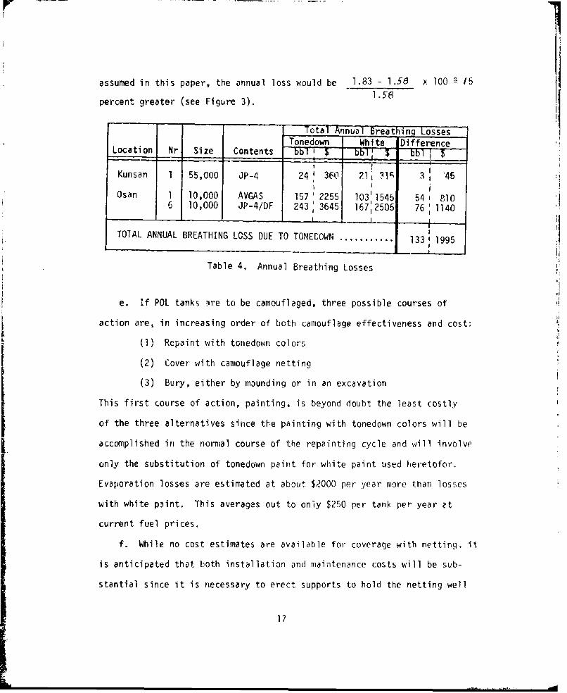
assumed in this paper, the annual loss would be 1.83 - 1.58 x 100 15
percent greater (see Figure 3). 1.8
Total Annual_ Breathin( LossesTonedown White Difference
Location Nr Size Contents bbl T_ bblI $ bbl $II I
Kunsan 1 55,000 JP-4 24 360 21 31• 3 ' 45
Osan 1 10,000 AVGAS 157' 2255 103 1545 54 1 8106 10,000 JP-4/DF 243; 3645 1672505 76 1140
TOTAL ANNUAL BREATHING LOSS DUE TO TONEDOWN ...........
Table 4. Annual Breathing Losses
e. If POL tanks )re to be camouflaged, three possible courses of
action are, in increasing order of both camouflage effectiveness and cost:
(1) Repaint with tonedown colors
(2) Cover with camouflage netting
(3) Bury, either by mounding or in an excavation
This first course of action, painting, is beyond doubt the least costly
of the three alternatives siiice the painting with tonedown colors will be
accomplished in the normal course of the repainting cycle and will involve
only the substitution of tonedown paint for white paint used lieretofor.
Evaporation losses are estimated at about $2000 per year more than losses
with white paint. This averages out to only $250 per tank per year "t
current fuel prices.
f. While no cost estimates are available for coverage with netting, it
is anticipated that both installation and maintenance costs will be sub-
stantial since it is necessary to erect supports to hold the netting well
17

above the roofs of the tanks in order to allow a working space between the
canopy and the tanks themselves. This entails internal restructuring of
the tanks because the tank roofs are not currently designed to support such
loads. Netting does, however, provide excellent camouflage and tanks
camouflaged by nets are not warmed by the sun, although their roofs and
walls are exposed to the ambient heat of the day and cool of the night and
so transmit this temperature change to the vapors within. This results in
breathing, but it is less than for an exposed tank painted white and so is
correspondingly less yet than for a tank painted with tonedown colors and
eyposed to the warming solar rays. How much less is not known, but it is
surely somewhere between the $800 per tank per year that would be saved by
burying the tanks and the $250 that would be saved by leaving them white.
On the other hand the cost of suspending wire netting above the tanks, while
less than the cost of burying the tanks, is clearly greater than the cost
of repainting them in tonedown colors, for repainting comes virtually free
of additional costs since it is to be done during the normal cyclic re-
painting schedule.
g. Burying tanks is more expensive than erecting poles and covering
them with netting. In this case the tanks must be reinforced to prevent
collapse of the sidewalls when the tank is empty. And the roof must be
strengthened to support the overburden of earth. A single wOu00 bbl tank
costs $73,000 more if it is buried. But, underground, tlere would be no
reduction in breathing losses from a floating pan. As seen from Table 5,
the cost saved by omitting the floating pan is $32,400. Furthermore, buried
tanks do not require protective ring walls; only direct hits are likely to
damage undergrcund tanks; and once damaged, the inflai'miable contents are
safely contained by the earth itself. Since a tyipical protective ring wall
for a 10,030 bbl tank in Korea costs in the neighborhood of $72,000, the
net saving is
$32,400 4 $72,000 - $73,000 $31,400
18

Cost of Cost Total CostType of Tank Tank Y! Ring Wall 2/ of Tank
10,000 bbl $108,000 $72,000 $180,000Above Ground
1o,O00 bblAbove Ground $140,400 $72,000 $212,400with Pan
10,000 bbl $181,000 Not Req'd $181,000Buried
55,000 bbl $306,900Abv rud 3690$205,000 $511 ,900Above Ground
55,000 bbl "Above Ground $524,700 $205,000with Pan
5uried bb] $739,200 Not Req'd $739,200 1Buried
IiSource: 1. Reference 9.
2. CINCPACAF/DE estimate.
Table 5. Costs of Tank Installations in Korea
19

which makes underground tanks very attractive in terms of current policy i:
which prescribes flc3ting pans for aboveground tanks. But, as shall be
seen in paragraph 6h, infra, floating pans are uneconomical and never pay
for themselves, even in tanks containing gasoline, as long as the "full
tank policy" is followed. Thus buried tanks, as compared with above-
ground tanks without floating pans, do not provile significant savings.
Furthermore, maintenance is a problem because earth must be removed to
effect repairs. But there is considerable attraction in the far superior
protection offered: with vegetation covering the soil over the tank,
camouflage can be very good indeed; only direct hits are likely to damage
buried tanks; and once damaged, the inflammable contents are safely con-
tained by the earth itself. Underground tanks suffer virtually no daily
breathing losses, for the warmth of the day and the rays of the sun never
penetrate to the region occupied by the vapors between the upper surface
of the fuel and the roof of the tank, so that the temperature within the
tank remains virtually constant over any twenty-four hour period and
varies but slowly from season to season. But not all soils are suitable
for burying tanks. And high water-tables can present a problem in keep-
ing tanks buried: the tanks tend to float up out of the earth. Nor are
suitable locations always available on the crowded air bases in Korea.
But where tanks are placed underground, evaporation savings can be as high
as $2255 per year for a toned down 10,000 bbl tank of gasoline without a
pan, and $600 per year for the same tank with JP-4 in it. Over the 30-
year life of a tank, these savings are not insignificant. But where there
is an option of storing either gasoline or JP-4 in an underground tank --
all else being equal -- the choice is clear: store the gasoline below
ground to reduce evaporation losses. The improved safety factor in placing
this more volatile substance below ground is also abundantly clear. Like-
wise, where there is an option of storing gasoline or JP-4 in a tank
equipped with a floating pan, the gasoline should be stored in the tank
with the floating pan.
20

h. From Table 5, it is seen that the cost of a floating pan in a
10,000 bbl tank is approximately $32,400.* How long would it take to
pay off this investment? To make this calculation, the cost C of the
pan over a period of n years, neglecting maintenance costs (which may
not be small, especially if the pan sinks, but are difficult to esti-
mate), is taken as
C = P (I + r)n
where P = initial cost
r = interest rate
This cost is to be offset against the savings S in cost of fuel saved
over the same period of n years
S L (l + r)n --1
r
where L = annual cost of fuel loss.
C is set equal to S and the resulting equation is solved for n
P (0 + r)n L ( r)-r
(1+ .)L (.-p) - k
(1 + r)n (TLP.In L
(I+ rn L -rP
taking logarithms of each side
n Log (1 4 r) L 'G L-r
LLog ( -- Wp)
n
Log (1 4- r)
The annual evaporation loss of gasoline from a toned down, welded, 10,000 bbl
tank at Osan, equipped with a floating pan is (per paragraph 5b, supra)
* Civil Ingineering cautions that this is a rough estimate. The cost would
be less as an increment in the purchase and erection cost of a new pre-fabricated tank.
21

=1.5 3.8] 0.7 5.20.7 Ks x 1.00 x 1.05
S t 14.7
= 653.71 (Kt KS)
= 29.4 to 39.2 ', 34.3 bbl/yr
" $514/yr @ $15/bbl
which is to be reduced by 12 percent to account for savings resulting from
pressure/vacuum vent. This leaves a value of
Ly • $437/yrL-yTo find the savings owing to use of a floating pan, then, this value is
subtracted from $2255, the annual lcss from the same tank without a float-
ing pan.
L = $2255 - $437 $1818/yr
If, also, r = 8% per annumP = 3L,4UU
n:then L og9(- L -T
Log (1 + r)
1818
Log ( T e-F )
Log 1.08
I --2i 35
Log 1.08
- more than an infinite number of years*
From this it can be seen that a floating pan can never pay for itself under
these circumstances. (But if the "full tank policy" were not followed, in-
creased losses might justify floating pans.)The maximum initial cost which can ever be paid off is P .-L 1818$
$22,725. (And even this would require an infinite number of years.)
22

i. Although working losses are not the proper subject of this re-
port, they cannot be divorced from any recommendation to dispense with
the floating pan. Paragraph 6h, supra, has set forth reasoning which
shows that floating pans cannot be justified by benefits accruing from
a reduction in breathing loss from tanks which are kept relatively
full (the PACAF "full tank policy"). Whether this be true or not of
tanks remaining relatively empty is moot since such a state would be a
violation of policy. On the other hand, what about tanks which are
worked significantly? Reference 7 states that withdrawal loss from
tanks equipped with floating pans is negligible, while reference 2 sets
forth the formula for the loss from one filling to the next as
L = 3PVKt x lO"4
wherc: P = true vapor pressure of fuel
V = volume of fuel pumped
Kt = (180 + N)/6Nwhere: N = annual thruput divided by tank
capacity
The factor Kt is considered unity for less than 37 turnovers per annui,.
Thus a 10,000 bbl tank of AVGAS at Osan with 10 turnovers per year would
suiffer an annutal wnrk-ng locs •f
Ly = 3 x 3.7 x 10 x 10,000 x 1.0 x 10-4
= 101 bbl/year
= $1515/year.
Since most of this would be saved hy a floatinr pan, the annual savings
of $1515 +$181P = $4343 indicate that a pan would, under these conditions,
pay for itself in
23

EXAMPH: I560C0 larI TankThuowpugl=15I 60O00 Sorrelt per Yoei toTu,"cw.S= 109.Tr,. Vapor Prosivre= 5.8 pt;a 90-
Wotk;.-g Loss f 7 S Serrei pee Y~or 8.0 17.0 90 V
- 6.0 -8101000 100-
9.0" 50 78.0 6.0
>-
3a. 7. *,o .0 .2500 c I - .
5 .0 -
.0- -. 0.. to 3 .0 .0
2000 - d*O 5. 9 - -. 0..
AD -- 0 1.5- 2.0.
-7
10 2.0 -O - 0 0 1.36 .'II~~ - -40 2.
6000t -12
60 1 . 250 - .0BOD Z 20S7-0
6000 . 1250 0.
100 330 0.6- 011000 102 400 os 07
a 06
0.4
033-
* 0.2-
-~015- 02
0 ~ Cc
0 to-0
0 0
0,07
1006 008"o
0.07
Note:flbc throunihput is diviJed by a number 1I, 10. 1041, 1.0)00) to bring it into the range of the sc~ic. 'I he wAorking 105%. read fromnn Olme
-calek. nmls then be nitmitirlied by the saivic mnumbem.
FIG. io -Warking log. cir cagslin maieci cruae Oil fronm Fistrol-Ron( Tanks.
24

n Log ( 4343- 2592~= L Log(1.0 )
Loq_2.4_8 0.394603
Log 1.08 0.033424
11.8 years
Thus it is seen that the decision whether to install a floating pan or
nmt depends to a very large degree upon thruput. Where use is made of
smaller tanks -- especially bladder tanks -- for working storage, larger
tanks being kept full, it is clear that floating pans cannot be justi-
fied even for gasoline storage. It is likewise clear that floating
pans cannot be justified for JP-4 storage irrespective of how the tankT.-
is worked.
25
25

14
7. CONCLUSIONS
a. Evaporation breathing losses resulting from camouflaging POL
tanks with tonedown paint on US air bases in Korea should not exceed
about $2000 per year, at present costs of $15 per barrel in place.
b. If tanks are buried instead of toned down, total savings of up
to $6200 per year in evaporation losses may bc realized over toning down
the tanks, and increased protection will result. But not all locations
are suitable for burying tanks, although net costs are about the same for
aboveground and for underground POL tanks.
c. If tanks are camouflaged with netting, evaporation losses will
be between present losses with while tanks and losses expected with buried
tanks; an evaporation loss saving over current practice and an even
greater saving over proposed tonedown painting. Netting installations,
however, introduce problems of handling, maintenance, accessibility, etc.
These factors are to be balanced against the better concealment afforded
by netting.
8. RECOMMENDATIONS
a. The present policy of burying tanks where possible should be con-
tinued. Burying results in maximum concealment, maximum protection, and
minimum evaporation losses.
b. The more volatile fuels, AVGAS and MOGAS, should be given priority
for underground storage to reduce evaporation losses and keep safety
hazards at a minimum. Where underground storage is not aiailable, these
fuels should be stored in tanks with fl)ating pans or with other means
of evaporation loss reduction.
26

c. Aboveground POL tanks may be camouflaged by paintifg them with
tonedown colors. Where AVGAS or MOGAS is stored aboveground, some con-
sideration should be given to the superior concealment obtainable with
permanent type wire netting because of the reduction in breathing losses
afforded.
i. The full tank policy of Hq PACAF should be continued since this
results in minimum breathing losses.
e. If construction requirements dictate that more aboveground tanks
are to be installed in Korea, they should be equipped with floating pans
only under special circumstances.
f. Small working tanks, preferably bladder tanks, may be used to
reduce working losses to a minimum.
21
27

REFERENCES
1. Evaporation Prevention Manual, an internal publication of Standard
oil Company of Cailfornia (SOCAL).
2. AP! Bulletin 2518: Evaporation Loss From Fixed-Roof Tanks.
3. Wright, Glenn C. Special Reflectance Characteristics of CamouflageGreens Versus Camouflage Detection "IRMA lI1", 11 Mar 53, Engineer Researchand Development Laboratories, Corps of Engineers, U.S. Army Report #1281.
4. Soil Penetrant-Colorant For Scarred Earth, Feb 69, Army Materiel Com-mand TIR 33.9.1.6.
5. Sell, Richard E. Camouflage Practices. Dec 67, USAF Aero-PropulsionLab, AFSC, AFAPL-TR-67-13M.
6. Scaff, William L. Jr.; Macias R., Frank M.; Bell, Robert E.; BiologcalMethods for Camouflage, Concealment and Tonedown. Northrop CorporateLaborf-t"res for USA Aero-Propulsion Lab, AFSb, AFAPL-TR-67-153.
7. API Bulletin 2517: Evaporation Loss From Floating Roof Tanks.
8. API ['"lletin 2521: Use of Pressure-Vacuum Vent Valves for AtmosphericPressure ..arhks to Reduce Evaporation Loss
). Cost Guidance for FY 76, Hq USAF/PRE
28

DISTRIBUTION
Hq USAF/SA 1 CINCPAC/J021 1PRE 2 J35 1
J42 1AFLC 1 J69
AU/AUL 1 CINCPACFLT (OEG) 1
MAC/OA 1 DDC 1DE 1
LG 1 RAND Corp 1
PACAF/DE 2LG 1XOA 10
5AF/DE 1LG 1
13AF/DE 1LG 1
SAC/NR 1DE 1LG 1
TAC/XPSY 1DE 1LG 1
USAFTAWC/OA 1
USAFTFWC/OA 1
USAFE/DOA 1DE 1LG 1
This Document
29 Reproduced FromBest Available Copy