Embed Size (px)
Citation preview

PARADIP PORT TRUST
BUDGETARY OFFER
FOR
Supply, Installation, Testing &Commissioning Supervisory Control and Data
Acquisition (SCADA) of Main receiving substation with other 09 substations installed
different location of Paradip Port Trust with 5 yrs AMC after warranty periods.
SUBMISSION ON OR BEFORE 02/04/2019
THE EXECUTIVE ENGINER (ELECT)
PORT ELECTRICLA DIVISION – II
PARADIP PORT TRUST,
PARADIP, JAGATSINGHPUR,
ODISHA – 754142
Contact No.9777-180-842
Email Id: [email protected]

REQUEST FOR BUDGETARY OFFER
a) GENERAL INFORMATIONS:
Sl.
No.
Item Details
1. Name of Work Supply, Installation, Testing & Commissioning Supervisory
Control and Data Acquisition (SCADA) of Main receiving
substation with other 09 substations installed different
location of Paradip Port Trust with 5 yrs AMC after warranty
periods.
. 2. Department /
Organization
ELECTRICAL & MECHANICAL DEPARTMENT /
PARADIP PORT TRUST
3. Executive Division Port Electrical Division.
4 Officer Inviting the Offer Executive Engineer
5. Immediate Next
Authority
Superintending Engineer
6. Sanctioning Authority Dy. Chairman, PPT
7. Executing Authority Executive Engineer
b) OTHER INFORMATIONS:
Sl. No. Item Date Time
1 Publication date 13.03.2019 17:00 Hrs.
2.a) Document download start date 13.03.2019 17:00 Hrs.
b) Document download end date 02.04.2019 17:00 Hrs.
3.a) Start date for seeking Clarification on-line 14.03.2019 17:00 Hrs.
b) Last date for seeking Clarification on-line 20.03.2019 17:00 Hrs.
4. Date of uploading response to Clarifications sought 29.03.2019 17:00 Hrs.
5. Offer Submission end date 02.04.2019 17:00 Hrs.
6. Offer Validity period 120 days
7. Currency of Offer Indian Rupee
8. Language of Offer English

Name of the Work: Supply, Installation, Testing & Commissioning (SITC) Supervisory Control and
Data Acquisition (SCADA) of Main receiving substation with other 09 substations installed different
location of Paradip Port Trust with 5 yrs AMC after warranty periods.
SCOPE OF WORK
Paradip Port Trust invites budgetary offer for Supply, Installation, Testing and Commissioning
(SITC) of Supervisory Control & Data Acquisition (SCADA) system of main control Room and other
09 substations located different location of PPT. The following works are to be taken up under this
system
1. The SCADA system shall cover Main Receiving Substation (132 / 33 / 11KV) and another 09
nos. of distribution substation of Paradip Port Trust as followings:
(i) V-Point S/S; (ii) Madhuban-II S/S; (iii) Radar S/S; (iv) Sector-9 S/S; (v) NAC S/S; (vi) Clean
Cargo S/S; (vii) Harbour S/S; (viii) 11 kV IOHP S/S; and (ix) BOT S/S.
The Contractor has to design the SCADA system for above substations considering the
requirement of numeric protection relay, energy meters / multi-function meters / tri-vector
meters, RTU panels and networking through OFC or wireless communication with each other
substations. The control room or command centre shall be installed in the 132 kV / 33 kV main
receiving substation building. The communication with other substation should be through only
wireless system, i.e. RF / WIFI / GSM / GPRS / 3G / 4G network. The SCADA system shall
have provision to add 40 substations (as future extension) for data storage, monitoring &
control.
The details of existing feeders & relays available in the substations are attached herewith as
ANNEXURE – A (07 sheets). By going through the details of existing relays, the Bidder /
Contractor has to select the type & quantity of numeric relay required for SCADA solution. The
Contractor has to replace the existing relay with advance with numeric relay suitable for
SCADA control system. Standard type of relay, RTU panel & data interface module shall be
used so that material of other standard manufacturer can be replaced in future and there should
be compatible with each other.
The Contractor shall supply RTU panels of reputed brands such as Siemens /ABB / Schneider
or other reputed manufacturer at Main Receiving Substation & other substations for
transmission and receiving data for SCADA control system.
The software, hardware and all materials & consumables required for SCADA control system
shall be supplied by the Contractor.
2.1 The Contractor has to supply numeric protection relay with following major technical
parameters besides other facilities:
a) Directional/Non Directional O/C protection relay:(67/50/51)
b) Earth fault protection: :(67N/50N/51N)
c) Voltage Controlled Over current: (51V)
d) Sensitive earth fault/Restricted earth fault: (64R)
e) Over voltage and under voltage; (59/27)

f) Over frequency/Under frequency /Rate of change of frequency (81O/81U/81R)
g) Power protection (32R/32L/32O)
h) Breaker fail protection (50BF)
i) Differential protection (87)
2.2 The following additional features of the relays are desirable:
a) Thermal overload protection.
b) Negative sequence over current protection.
c) Circuit breaker maintenance information.
d) CT supervision.
e) VT supervision.
f) Broken conductor detection by measuring I2/I1.
g) Cold load pickup function to change the settings when the protected object is connected to
a network i.e. at starting allowing the set value being lower than the connected inrush
current.
h) Trip Circuit Supervision.
i) Contact & LED test capability without using any testing instrument.
Besides that the relay shall have at least four independent setting groups. The relay shall
automatically switch from one setting group to another depending on system conditions (such
as failure of incomer supply, which causes fault level to decrease etc.).
2.3 The relay should be modular draw out type, suitable for either rack or panel mounting.
Standard terminal blocks should be located at the rear of the relay providing connections for all
input and output circuits. Relay should work with Auxiliary supply of 110V to 250V D.C. &
100V to 240V A.C. Relay should have total 5 nos. of CT (range 1A or 5A selectable at site) & 3
nos of VT input (Range 110V to 120V A.C.).
2.4 The relay in addition to protection and control should store all parameters in non volatile
memory so that in case of failure of auxiliary supply relay parameters remain intact. The feature
of the relay should be accessed through a front panel backlit LCD display with minimum 32
character alphanumeric type display. The relay should record all the events affecting and
affecting the relay performance and shall store at least 500 nos of time tagged events with 1 mili
second resolution in its battery backed memory. The relay shall also store at least 5 nos of latest
fault records containing the following information and same shall accessible from front panel
LCD display
i) Indication of faulted phase.
ii) Protection operation.
iii) Active setting group.
iv) Date and time.
v) Current, voltage and frequency.

2.5 Disturbance recorder shall have memory to store minimum 50 nos. of records with 0.5 second
record duration. Disturbance record wave form shall consist of minimum 3 nos of voltage
channels, 5 nos of current channels and 32 nos of digital channels. Recorded disturbances can be
stored in local PC and/or station PC in complete format for further analysis. The relay shall
have RS232 or USB front port for communication with laptop, fibre optic and R145 rear port for
communication to SCADA or any other station communication system. The relay should have
at least 8 optically isolated inputs and at least 7 programmable outputs apart from one
dedicated output relay (N/O & N/C type) should be permanently assigned for self-supervision.
The relay shall have minimum 8 nos. of freely programmable LED. The digital output contact
ratings of the relays shall be as follows:
a) Rated voltage 300V.
b) Continuous current: 10A
c) Short duration current: 30A for 3s
d) Mechanical Durability > 10000 operations.
2.6 The relay PCB shall have conformal coating so that the relay can be used in harsh & corrosive
environment. The relay shall have the facility of communication on industry standard open
protocols. The relay should have a RS 485 port for local engineering station. There shall have a
facility to have IEC61850 protocol inbuilt without use of any external converter and should
support GOOSE message of class-1 type to support faster transmission of message with 4ms.
The relay shall have facility for time synchronisation on SNTP, RS485 and through digital input.
The relay should measure the following standard quantities with accuracy± 1% of the full scale,
a) Phase current (positive, negative and zero sequence currents).
b) Phase voltage (positive, negative and zero sequence voltages).
c) Neutral current.
d) Frequency.
e) Thermal state.
f) Active and Reactive Power.
g) Energy
IEC 60529: 1992 for enclosure protection: IP 52, IP 50 & IP 10 for front, side & rear side of the
relay respectively and
Operating temperature range: 250C to + 550C,
Ambient Humidity Range As per IEC 60068-2-3, 56 days at 93 % relative humidity.
Corrosive Environments As per IEC60068-2-60:1995, to elevated concentrations of H2S, NO2, CL2
, SO2. Insulation: As per IEC 60255-27:
High Voltage (Dielectric) Withstand: As per IEC 60255-27: 2kV rms AC, 1 minute.
Immunity to Electrostatic Discharge: As per IEC 60255-22-2: Class 4.
Radiated Immunity from Digital Communications: As per EN610000-4-3.

Vibration Test: As per IEC 60255-21-1
Shock and Bump: As per IEC 60255-21-2
Seismic Test: As per IEC 60255-21-3
The relay shall have Cyber-Security facilities (NERC compliant) to avoid unauthorised access
and control.
3.1 The RTU shall cover the following requirements:
Proven track records to various utilities for their Transmission and Distribution network.
It shall be demonstrated that the same range of RTUs have already been installed,
commissioned and in operation in High Voltage environment for period of more than 5
years.
The RTU shall be based on a truly distributed design allowing any flexible combination
and distribution within the various substation areas or building being able to cope new
configuration with serial IEDs as well as for refurbished substations where large IO
quantities are required (around 20 or more, dealing with 2000 data points).
The RTU shall allow flexible, scalable and reliable integration of control, monitoring;
metering, power quality, fault recording and automation functions. It can be used for a
wide range of bays from medium-voltage substations.
The RTU shall comply with latest state of the Art Ethernet Based technology hence using
open system standard, at least 32 bit processor on the CPU board, possibility to integrate
some Optical Ethernet switches interface under 100Mbit/s technology. Should several
racks be used all the required interfaces between racks shall be embedded within the rack
hardware and not require any external switches.
The RTU shall allow latest HMI LCD display technology to be used on main RTU rack
allowing operator to access detailed substation alarms and events data without the
absolute necessity to use laptop computers. In the meantime laptop port should be
available for any major local database changes to be managed.
The RTU shall comply with applicable standards and shall equally satisfy the technical
requirements stated in European (CE) and International specifications (IEC – International
Electro technical commission).
The RTU shall be rugged and offer cyber-security facilities (NERC compliant), to avoid
unauthorised local access and control.
3.2 The RTU shall offer the most flexible and innovative communication speeds including at least:
Standard open SCADA protocol for data master-slave exchange through lower bandwidth
communication medium at least IEC60870-5-101 on master as well as slave.
For substations equipped with higher bandwidth communication data access (typical
optical backbone access) Ethernet based SCADA protocols shall be available at least IEC
60870-5-104
Ethernet based substation protocols for substation operator and asset managing engineers
(Ethernet IEC 61850)

For serial interface with Substation IEDs RS485 links using IEC 60870-5-103, DNP3 and
MODBUS shall be available. The Modularity of the racks shall be made so that 20 IEDs can
be connected serially to a rack through these links without jeopardizing the expected
response time at the SCADA level.
Should local Ethernet communications be required within the Substations the option to
include integrated Ethernet switch board shall be available.
Local SCADA HMI for local control & monitoring
3.3 Substation Local Interface:
The RTU shall include a local LCD screen to cover the need of operators to access data while
located into the Substations. These LCD shall cover the following functions:
Optionally the possibility to control (Open/Close) the main substation switching devices
(Incoming breaker)
Access to all Substation time stamped alarms ; while some configurable LEDs should be
available within the RTU front displays for the main groups of alarms, the operator shall
be able to navigate within this screen to further analyse the root cause of a given alarm
Access to all event logs
The basis of operation of this front display is to allow SCADA operators to inform Substation
operator of any alarm of event within a given substation, while the substation operator keep
access to all data history within the substation once they are there for troubleshooting purposes.
3.4 Communication with SCADA/DMS Master:
For distributed configuration consisting of several RTU racks, any rack can have the flexibility
to be designed as a the data concentrating interface to the upstream SCADA, concentration data
from any other rack without jeopardizing the response times expected at the master station
level. At least the following serial data port options shall be available: IEC 60870-5-104, IEC
60870-5-101 and DNP3.0 (serial and IP).
The RTU shall also have the capability to interface with several master stations of different
types in the same time, covering the possibility to at least interface through 4 independent
redundant ports (more than 8 ports in total).
Physical interface options shall cover the following possibilities: RS232, RS485, RJ45,Optical
Multi-mode medium or Optical Mono-mode medium.
3.5 Digital Input Processing:
All standard processing algorithms shall be provided for the standard signal types such as single
digital inputs, double digital inputs, transformer tap indications, etc.
Each of these signal types shall have the required number of conditioning parameters
associated with them, e.g. inversion of input state, filter times, scaling parameters etc. These
shall be configurable on a point by point basis.

All status changes shall be time stamped to a resolution of 1mS. Detection of multiple changes of
status between scan (MCD – Momentary change detection) shall be supported and the MCD data
is reported by exception for IEC 870-5-101 protocol.
3.6 Pulse accumulators:
These are assumed to be either single pulse accumulators / counters. Each pulse accumulator
shall be presented to the RTU as a single digital input or a complemented digital input
respectively. The points regarding the digital input above would therefore equally apply to these
inputs.
The value of the counter represents the number of pulses counted since the loading of database
or since the counter roll over or since a voluntary reset.
3.7 Digital Outputs:
Digital output card shall allow pairs of trip / close outputs. In addition to this, depending on the
configuration the output shall be configurable of Transient or Persistent type.
The outputs shall be presented as single pole Form A contacts. As applicable to the protocol
(IEC60870-5-101), the Controls shall be configurable of immediate type or of Select Before
Operate mode.
RTU shall support Dummy breaker (simulated CB to check end to end Communication with the
SCADA).
3.8 DC Analogue Inputs
The DC analogue input can be acquired by the RTU through transducers; each input is to be
isolated and shall be selectable individually among various ranges:
Current inputs: +-20mA, 4-20mA, 0-5mA, 0-10mA, 0-1mA
or Voltage inputs : 0-5Vdc , 0-10Vdc, +-10Vdc
Analog input accuracy shall be <= 0.1%. The CAD converter type is: 15bits + Sign.
3.9 AC Analogue Inputs (Curent /Voltages)
The AC analogue input (current/voltage) shall be acquired by the RTU through transducerless
acquisition when no transducers exist yet or through transducer inputs for existing substations.
For RTUs covering several circuit the RTU shall have the flexibility to interface up to 16 CT/VT
interfaces directly. These CT/VT interface shall allow for each circuit measuring of all key
parameters, at least Frequency, Watt, VA, Vars, Phase angle, Power factor.
The DC analog input option shall be converted through a 16bit A/D converter (15 bit + sign).
These signals correspond to the voltage and current DC delivered by Transducers
3.10 DC Analogue Outputs
The DC analogue outputs are to be secured and powered with an external source (output
maintained when the RTU power is Off).

Each output is to be isolated and shall be selectable individually among various ranges: +-
20mA, 4-20mA, +-5mA, +-10mA, 0-5mA, 0-10mA
Analog output accuracy shall be <= 0.1%.
Each analog output is associated to a “read-inhibit” output contact, signaling the stability of the
output value.
4.1 Automation
For each feeder a sectionaliser automated function shall be provided. It shall open automatically
the switch during the absence of voltage during recloser cycles. The number of faults and the
cycle duration shall be configurable. In addition, a general purpose automation language shall
be integrated and shall be compliant with IEC 61131-3 standard
4.2 Local MMI
On the front panel of RTU, LEDs and push buttons shall provide the following statuses and
controls:
- Status of all communication ports
- Switch position status
- Switch position control. The switch position control shall be validated by pressing
simultaneously 2 buttons in order to avoid unexpected manual control orders.
- Earth switch position
- Fault current detection
- Battery and power supplies status
- Local remote status
- Local remote control push button
- Automation status and control push button
- Fault detection reset control push button
The control and status related to each of the switchgear shall be presented in a clear and
ergonomic way, assuming that for each switchgear a clear area is dedicated to each switchgear
on the front panel.
4.3 Other local MMI
Locally, a Web Server interface shall be provided for connection of a laptop PC, a tablet or a
Smartphone in order to access to more details data such as alarms log, statuses and position,
and measurement.
4.4 Communication with SCADA
The RTU shall be able to communicate with the SCADA on 2 channels. In case of redundancy
the SCADA will activate the backup communication channel. The RTU shall be able to initiate
also a communication on the backup channel in case of detection of inactivity on the main
channel.The RTU shall accept communication with 2 SCADA simultaneously.

4.5 Protocol
The RTU shall comply with IEC 870-5-104 IEC 870-5-101 DNP3.0 standard protocol. The RTU
shall support Secure Authentication according to IEC 62351-5.
4.6 Transmission
The communication system is based on GPRS/3G/4G/ RF(free frequency band) / optical fiber.
The RTU power supply shall be sized to supply the communication modem. RTU shall transmit
data to the SCADA all the status and measurement. Each data shall be individually configurable
to be sent or not to the SCADA.
The measurement shall be spontaneously sent to SCADA according to configuration of :
- Threshold
- Dead band
4.7 WiFi:
A WiFi communication port shall be offered to access locally to the RTU. It shall be secured by
means of
- Activation/deactivation from the SCADA
- SSID visibility configurable
- Passphrase
- Automatic disconnection by timeout
5. Communication LAN for other devices
In order to ensure that future needs should be covered, the RTU shall be able to provide
additional communication ports:
- Ethernet port
- RS232/RS485 port
6.1 Power supply
The RTU shall include a power supply which integrates a 12Vdc battery charger
The battery charger shall be compensated in temperature and protected against deep discharge
and overvoltage. A single 12Vdc battery is mandatory in order to limit the maintenance
constraints.
In case of absence of the battery, the power supply shall be able to supply at least the RTU.
The power supply, from the battery voltage, provides the following:
- 110Vdc or 48Vdc± 10% for the motorisation. This voltage shall be connected only in
execute phase.
- 12Vdc for the transmission devices.
- 12Vdc for the RTU modules.

6.2 Power supply input
Input voltage: 230Vac± 10%
The power supply shall be insulated to 10kV and surge protected up to 20kV , in compliance
with IEC60255-5.
6.3 Battery
The battery capacity shall maintain a backup time of 10 hours for all the voltage outputs and
shall permit 10 Open/Close cycles of the switchgear.
The single 12Vdc battery shall be periodically checked, and a battery fault shall be transmitted
to the SCADA.
The maximum battery charging time shall be 24hours
6.4 Monitoring
The power supply shall deliver the following statuses to the SCADA
- End of life detection
- Battery disconnected
- Absence of power input
- Voltage output faults
- Battery fault
Any other data should be available through a serial link communication.
7.1 Cyber Security
In order to secure all controls and data acquisition, the RTU shall be designed to be compliant
with NERC and IEC62351 requirements. The RTU shall support secure access based on RBAC,
with the possibility to configure the roles.
Local and remote access connection shall be secured for maintenance (locally and remotely)
with HTTPS, SFTP and SSH protocols.
Authentication shall be based on a Radius server.
7.2 Interface minimization
Each interface shall support only the data types and protocols needed to meet the functional
requirements.
Unused interfaces and ports shall be removed. If removal is not possible, the unused interfaces
and ports shall be disabled.
A complete list of supported data types and supported communication protocols per interface
shall be provided.
All hardware interfaces that are used for programming or debugging shall be completely
removed after production.
Communication
Compliance to Security standards
The RTU shall follow the IEC 62351 standards and at least:
IEC 62351-5: 2013
IEC 62351-3
Configuration
Access to the RTU by configuration tool shall be possible only through secured connection:
HTTPS for Web server and SSH for console and configuration tool.
Access control
RBAC
The RTU shall support the implementation of Role-based Access Control in compliance with
IEC 62351-8.
It must be possible to configure the privileges of individual roles. It must be possible to carry
out changes by configuration files through a secure way.
It must be possible to define more roles for future applications.
It shall be possible to assign each role individual security credentials.
It shall be possible to bind roles to individual user accounts on the RTU.
The minimum following function and data shall be controlled through RBAC:
Configuration files
Software update
User management
Executing program or shell command
I/O on local maintenance access
A specific tool shall permit to configure the security policy, role and password.
Management of Security passwords
The RTU service application shall support individual user passwords.
Passwords shall be stored together with a salt using an allowed cryptographic hash function.
The RTU service application shall enforce a high complexity of passwords.
The RTU shall lock the access after several password error.
User Authentication
The RTU shall authenticate the communication parties on the WAN interface using a challenge-
response protocol based on message authentication codes The RTU shall terminate the
connection if the user authentication fails.
The RTU shall authenticate the communication parties on the Local Maintenance interface.
It shall be possible to configure the RTU so that it blocks authentication requests, either
temporarily or permanently, from an account after a number of failed login attempts. The
number of failed login attempts and the time the account is blocked shall be configurable.
Central Management of user account
The RTU should allow to manage user authentication through a Radius server.
Security Log
The RTU shall provide a local audit trail for all security events that occur.
Log files shall be produced in Syslog format.
Security events shall be logged locally in a dedicated security log or/and on a SYSLOG server.
Documentation
Secured Versioning
All released versions (hardware, firmware, software) of a device or product shall be uniquely
identifiable.
Exchangeable hardware modules shall be versioned separately.
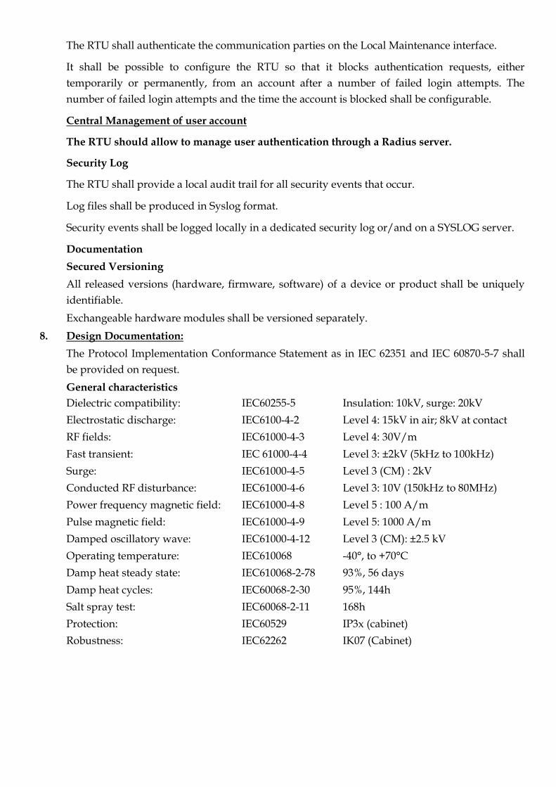
8. Design Documentation:
The Protocol Implementation Conformance Statement as in IEC 62351 and IEC 60870-5-7 shall
be provided on request.
General characteristics
Dielectric compatibility: IEC60255-5 Insulation: 10kV, surge: 20kV
Electrostatic discharge: IEC6100-4-2 Level 4: 15kV in air; 8kV at contact
RF fields: IEC61000-4-3 Level 4: 30V/m
Fast transient: IEC 61000-4-4 Level 3: ±2kV (5kHz to 100kHz)
Surge: IEC61000-4-5 Level 3 (CM) : 2kV
Conducted RF disturbance: IEC61000-4-6 Level 3: 10V (150kHz to 80MHz)
Power frequency magnetic field: IEC61000-4-8 Level 5 : 100 A/m
Pulse magnetic field: IEC61000-4-9 Level 5: 1000 A/m
Damped oscillatory wave: IEC61000-4-12 Level 3 (CM): ±2.5 kV
Operating temperature: IEC610068 -40°, to +70°C
Damp heat steady state: IEC610068-2-78 93%, 56 days
Damp heat cycles: IEC60068-2-30 95%, 144h
Salt spray test: IEC60068-2-11 168h
Protection: IEC60529 IP3x (cabinet)
Robustness: IEC62262 IK07 (Cabinet)

SCADA TECHNICAL REQUIREMENTS
TECHNICAL SPECIFICATION
System Architecture Included in the SCADA system’s family of products shall be a Graphical User
Interface (GUI), a fully integrated Real-Time sub-system, and a fully integrated Relational Database
Management System (RDBMS).
The SCADA system shall also provide for easy and open integration with third-party application
software via non-proprietary industry standards.
The SCADA system shall provide capability to extend real-time data from the field to the enterprise
by providing access to operational and historical data anytime, and anywhere.
The SCADA system shall allow Corporate Information Systems and specialized applications
packages access to the SCADA data.
The SCADA system architecture shall utilize non-proprietary industry standards to enable
transparent connectivity to other hardware, software and networks.
The Vendor shall adhere to Customer security policies and procedures in order to ensure the overall
security of the Vendor’s proposed SCADA system, Corporate Information Systems, and associated
specialized applications.
Where such policies and procedures require further clarification because of this SCADA project, the
Vendor shall provide security specialists for consultation with Customer IT and security staff.
The SCADA system shall leverage the infrastructure of the native operating system using the
Kerberos authentication protocol. Users accessing the SCADA system via the Internet shall
authenticate using the x.509 standard certificates.
The SCADA system shall provide for single sign-on that shall reduce redundancy and shall simplify
user security management by permitting central administration of security from the common Active
Directory Service (ADS) and/or AD LDS (Active Directory Lightweight Directory Service).
The SCADA system shall use the Active Directory Service, which may include AD LDS, to manage all
users, security and resources.
SSO (Single Sign-on) strategies shall centralize security administration tasks and definitions and shall
free the SCADA system from proprietary control of user name and passwords, as well as reducing
the burden on users to re-authenticate.
Use of the SCADA system and its security shall not cause end users to come into conflict with the
Customer’s enterprise-wide security practices and standards.
A SCADA system management application or application bundle shall provide an overview of which
hosts and subsystems are active in the SCADA system network, what role they are performing, and
what their health is. The management application shall be very quick to call up, and/or constantly
running on SCADA workstations and servers. With due consideration of user privilege and
restrictions, the application shall permit start/stop and change-role control over the various hosts,
and redundant systems and distributed systems.

Administrators shall be able to quickly assess, diagnose and respond to the health of components on
the SCADA network.
It shall be possible to use the above-mentioned SCADA management application to configure and
administer:
(i) Sub-systems; (ii) services; (iii) computers; (iv) devices; and (v) users, authorities and permissions
It shall be possible to use the above-mentioned SCADA management application to monitor:
(i) service states; (ii) processes; (ii) machine health; and (iii) error logs
The SCADA management application requirements are described further in 0.
The SCADA system architecture shall utilize non-proprietary industry standards such as TCP/IP,
ANSI SQL, ODBC and Extensible Mark-up Language (XML) encoding.
The SCADA system shall provide tools to view trends of historically-collected data.
The SCADA system shall be configured using industry standard, unmodified hardware and
operating systems. The hardware and Operating System shall be suppliers’ standard products and
shall constitute the primary components for the system.
The SCADA system shall not be dependent upon specialized, unique, or proprietary equipment or
third-party software components available from only a single supplier.
Under normal operating condition, in no case shall it be necessary to shutdown and/or restart any
systems in order to activate or deactivate the processing of data at a system.
Distributed System Architecture
The SCADA system shall conform to the concepts of a distributed information system.
Components provided as part of the Vendor’s SCADA system must have the ability to share real-time
and historical data between independent SCADA subsystems and geographical locations. This shall
enhance the overall system reliability and functionality by providing shared access to components
and applications.
The Vendor’s distributed system shall provide configuration options that allow multiple systems to
share telemetry data, alarming, eventing, telecommunication, and control functionality.
User permissions and security restrictions regarding all aspects of the SCADA system shall propagate
seamlessly across the SCADA system’s distributed architecture.
All computers in the SCADA system shall connect with each other using the latest industry standard
Local-Area Network (LAN) and Wide-Area Network (WAN) technology.
The SCADA system peripherals shall connect either directly to the SCADA LAN, through servers
connected directly to the system's LAN, or attached to workstation parallel or serial ports. This shall
allow access to any device from any computer in the system with the appropriate access authority.
The SCADA system shall provide support for distributed network equipment such as terminal
servers, networked printers, networked PC's, and mass storage/backup devices.

The SCADA system shall provide item by item replication of data across the SCADA system’s
distributed architecture. The direction of the replication shall be configurable based on data
groupings that pertain to data ownership (where the data originates) and where the data is required.
To handle the large amounts of data being exchanged between systems without requiring excessive
WAN bandwidth usage, real-time data shall only be shared between those systems with defined
relationships within the distributed architecture.
It shall be possible to define these system relationships to share all records or only specified fields
within records. To further reduce the network load between locations, it shall be possible to store
historical data locally by each system, or to store historical data only on the owning system and
replicate the historical data to other systems.
The SCADA system shall employ a mechanism to allow simultaneous configuration of database
points or records from two or more systems across the SCADA system’s distributed architecture,
while still maintaining database integrity.
Supported Architectures
The SCADA system shall provide flexibility and expandability of the initial system to accommodate
changes with a minimum of cost and effort.
The Vendor’s base product shall also support PRIMARY/BACKUP, PEER TO PEER, MASTER/SUB-
MASTER, and TEST/DEVELOPMENT architectures. (The Vendor’s “base product” refers to the
version of the product as developed and released by the Vendor’s R&D group. The “base product”
means that the requested configuration can be accommodated without customization, recompilation
or regeneration of the entire system. It is understood that some changes may require licensing
additional Vendor products or modules.)
Each SCADA system (consisting of real-time and historical servers, required functionality of which
are discussed later on in this document) shall be capable of single or redundant real-time and
historical servers.
It shall be possible, but not obligatory, to conflate the real-time and historical roles onto one server or
set of redundant servers. Conversely, it shall be possible to host those services on separate servers,
depending on load. This is a one-time, initial setup decision, agreed to in the System Configuration
Plan (SCP).
Each SCADA system shall be capable of supporting a Decision Support Server (DSS) or servers to
supply data to Corporate and other non-SCADA users. The DSS shall operate in a view only mode
(having no control or configuration capability).
PRIMARY BACKUP:
It shall be possible to configure the Vendor’s base product such that one system operates as the
primary control and operation system, and second system operates as the backup system.
PEER TO PEER:
It shall be possible to configure the Vendor’s base product such that each system nominally monitors
and controls a subset of the overall data, and each system also functions as the backup for the other.

MASTER/SUB-MASTER(S):
It shall be possible to configure the Vendor’s base product such that one system monitors and
controls all field data, with many sub-master systems responsible for field communications.
OFFLINE TEST/DEVELOPMENT:
It shall be possible to configure the Vendor’s base product such that one of the systems may operate
as an offline Test and Development (T&D) system used to implement and verify changes to the
SCADA system before deploying them to the production environment.
Depending on the configuration and the relationships defined between SCADA subsystems across
the SCADA system’s distributed architecture:
a) field devices owned by one system shall be controllable by another system
b) systems can act as backups for other systems
c) all or part of the real-time and historical data belonging to a given system can be shared with
other systems
In this way, real-time functional elements of the SCADA system shall inter-operate regardless of their
physical location, allowing elements in separate locations to “know” what the other systems are
doing.
It shall be possible to add layered applications onto the Vendor’s base product without shutting
down a dual-redundant system.
Middleware Requirements
Data Publishing
The Vendor’s software shall make real-time data available via a publishing mechanism such that
third-party applications can capture data that is of interest, such as changing states or values. This
mechanism shall allow distributed "event-driven" applications.
The data publishing capability shall permit one application to transmit or publish information to
other applications without waiting for the other applications to receive the information.
Additional data subscribers shall have no impact on the performance of publishers or the other
subscribers.
The Vendor shall ensure that the publisher/subscriber middleware provided consists of the following
attributes:
a) distributed
b) bi-directional
c) guaranteed message delivery during normal operations
d) data integrity update after network connectivity restoration
e) high performance
f) multithreaded
g) able to deliver messages across multiple routed network segments
h) able to integrate with non-real-time publisher/subscriber systems

API Data Access and Functionality
An API shall permit third-party applications to obtain and modify real-time and historical data, as
well as performing actions from system user defined or third-party applications, such as (but not
limited to) creating alarms and events, or acknowledging them.
Updates to the API components shall not require downtime. If downtime is necessary, it shall be kept
to a minimum and the downtime that shall be covered through the use of the distributed system
architecture.
Remote Access
The SCADA system shall support a protocol that provides the data communications corridor through
which all Controller-Machine Interface (CMI) clients exchange data with the system’s servers,
complete with encryption and compression for the transported data. Users will be presented the
choice of service the CMI clients are able to connect to.
SQL (Structured Query Language) Access
Data access and update capability to both real-time and historical data shall be possible through the
use of SQL.
ODBC, OLEDB, ADO and similar industry standard SQL interfaces shall function with the SCADA
real-time and historical databases.
System Redundancy through a Distributed Architecture
Due to the critical nature of SCADA system functions, there shall be no single point of failure on any
critical system component. A critical component is any component whose failure directly and
adversely affects the SCADA system's overall performance or its ability to continue performing
critical functions of monitoring and control.
The SCADA system shall make use of modular components such that the failure of a single
component does not render inoperative other components.
The SCADA system shall provide redundancy for all critical processes.
The components comprising the standby system shall receive continually updated data, as
appropriate, to provide a "hot-standby" capability in case of a hardware or software initiated fail-
over.
The SCADA system shall make connection(s) to any Corporate or other networks in such a way that a
failure of any of these networks shall not affect the SCADA system's ability to perform its critical
functions.
The redundancy model shall be self-healing with critical processes and devices being monitored by
health monitoring software provided by the Vendor. This shall be considered a key component of
system robustness and for ease of support and administration.
The health monitoring software shall check critical processes and devices for failures, and take the
least intrusive course of action to recover from any failure.

Self-healing may mean that the SCADA system could end up in a non-default yet functional state,
with administrative intervention required to return the system to its default state once the cause for
failure has been determined and acted upon.
Self-healing capability must function to the level of preventing any single failure from rendering the
SCADA system inoperative. For combinations of failures (more than a single point of failure)
additional redundancy may exist, such as the ability to transfer duties to another site (e.g. DRC) or
another system in the SCADA system’s distributed architecture, but such decisions will require
administrative action.
System Overview and Design
The SCADA system shall provide a real-time platform exposing data and functionality by open
connectivity standards such as ODBC, XML, ADO, JDBC, OLEDB, SQL, JAVA, and SOAP.
The SCADA system shall accommodate interconnectivity options and data store connectivity portals
for legacy and future third-party enterprise IT systems.
The SCADA system shall include open connectivity standards that enable integration with
applications and systems such as:
a) Microsoft® Reporting Services
b) Microsoft® Excel, Microsoft® Access
c) Crystal Reports
d) Large enterprise applications such as SAP, PeopleSoft, Siebel, and ERP systems
e) Internet or Intranet
f) Sybase, OSI soft PI, Aspen Tech, Oracle, DB2, and MSSQL data stores
It shall be possible to add, remove, upgrade or replace Applications in a building block fashion.
The SCADA system shall functionally consist of three main components:
a) real-time and time-critical applications
b) Controller interface applications
c) historical data storage
The real-time and time-critical applications, and Controller interface applications, shall be considered
critical and essential to the safe operation of the SCADA system.
The historical data storage shall provide data capture for historical data analysis, enterprise
application integration, and regulatory reporting needs.
These categories shall further be subdivided into the following types of functions in each category:
a) Real-time SCADA and time-critical applications:
(i) Application specific time-critical processes; (ii) real-time database applications / support; (iii)
application specific non-time-critical processes; and (iv) system security applications and
processes.

b) Controller interface applications
(i) interface support; (ii) applications; and (iii) Controller interface.
c) historical data storage
(i) historical database; (ii) historical data capture; and (iii) application specific historical data
manipulation processes
The real-time SCADA and time-critical applications provided by the Vendor shall be considered the
most critical category of functionality as they provide the basic monitoring and control capabilities of
the SCADA system. Typical functions in the real-time SCADA and time-critical applications category
include:
a) data acquisition
b) engineering units conversions
c) alarm detection and annunciation
d) alarm/event logging
e) interaction with the CMI
f) general control output and status change validation
g) maintenance of the system's real-time database
h) monitoring of the system performance
i) capture of instantaneous data to support historical and regulatory data requirements
j) topological analysis
k) switching validation
l) switching plan writing and execution
m) Maintenance of the network model.
Typical real-time database support functions provided by the Vendor shall include applications such
as:
a) on-line calculations/derived values
b) database save/transfer utilities
c) real-time data sampling
Typical graphical interface support functions provided by the Vendor shall include applications such
as:
a) output of Controller and software initiated control commands
b) alarm annunciation/alarm logging
c) updating alarm displays
d) responding to periodic requests to display real-time data
e) publishing of real-time data for display
The Vendor shall provide Controller applications comprising the next most critical area of
functionality for the system, and shall include the following functions:
a) data presentation

b) display navigation
c) data manipulation
d) control actions
e) alarm presentation
f) Controller entry of parameters or data
g) report generation
h) display printing operations
Supporting functionality for Controller applications includes:
a) display generation
b) display format editing/SCADA system maintenance
Notwithstanding the importance of data capture to feed the historical data storage module (see (i),
above), the historical data storage module provided by the Vendor is considered the least critical
function. Although the functions of this module support the operation of the field system, none of the
functions shall require data in real-time. The SCADA system shall provide the following typical
functions in this category:
a) data archival/retrieval
b) historical data manipulations/calculations
c) device operating times
d) interface to the Corporate network
The data acquired through real-time data acquisition shall be buffered for a limited time (up to 24
hours) should the ability to store the data in the historical data module be temporarily unavailable.
SCADA System Configuration, Monitoring and Control Management Environment.
The Vendor shall provide a single management environment (application or suite) for SCADA
software configuration, monitoring and control.
This management environment shall include the following attributes:
a) accessibility from any machine in the SCADA installation
b) enable monitoring of SCADA software and machine states
c) enable viewing of machine log files
d) enable viewing/modification of all SCADA machine/database/application privileges and user
Areas of Responsibility
e) enable viewing/modification of SCADA system and machine properties
f) enable addition/removal of SCADA software systems from the SCADA domain
g) enable addition/removal of SCADA machines
h) enable SCADA software and third-party integrated component control (i.e. start
up/shutdown/failover)

Communications
There shall be three primary forms of communication which shall be inherent in the SCADA system
as follows:
a) synchronous/asynchronous communications (dedicated circuits and dial-up circuits)
b) Local-Area Networks
c) Wide-Area Networks
The SCADA system shall support various types of physical networking media (e.g., fiber optics,
shielded twisted pair, microwave, radio, satellite, etc.). The use of any particular type of networking
media shall be transparent to the system.
The SCADA network interface hardware and software shall handle any inherent differences between
these various types of physical network media.
The redundant SCADA LAN shall use an industry standards compliant LAN technology operating at
a minimum speed of 100 Mbps with support for 1Gbps.
The SCADA LAN shall be fault-tolerant and shall utilize a network configuration, which shall
prevent any single point of failure disabling the system.
The LAN shall be redundant and shall support shared data paths or 100 percent operation on either
LAN.
All Wide-Area Networks shall be logical extensions of the Local-Area Networks. Any interfaces
between LANs and WANs shall be through routers, bridges and/or concentrators and data control
units.
All LAN/WAN communication equipment shall support the following common features, as
applicable to the type of equipment used:
a) network management - SNMP (Simple Network Management Protocol), CMIP (Common
Management Information Protocol), or both
b) multiple Protocol - TCP/IP, X.25, etc.
c) IP routing
d) destination address filtering
e) protocol filtering
f) source address filtering
g) spanning tree algorithm
The SCADA system shall include system management tools for
monitoring/analyzing/troubleshooting of all system Local-Area Networks, Wide-Area Networks
and connected equipment.
Network Interface Cards
Each SCADA server shall have two network interfaces, implemented as two separate Network
Interface Cards (NICs), or as dual ported NICs. Each port shall plug into a separate switch.
Failure of a NIC shall not affect any of the SCADA server processes.

Each NIC shall support IPSec to encrypt all data traffic on the LAN.
Data Acquisition Equipment
The SCADA system shall be capable of gathering data from various RTU/PLC and IED units in the
field. The communication media may be leased lines, dial-up telephone circuits, fiber optic cables,
radios, and microwave or satellite channels.
The SCADA system shall be capable of supporting more than one alternative communication paths.
The SCADA system shall also provide for automatic failover to the alternate path(s). If the Automatic
Failover to Alternate Path is set, the system shall monitor the alternate path on a regular basis, and
fail over to the alternate path when the primary path is declared failed.
The SCADA system shall be capable of supporting the required protocol(s) over communications
path, provided the appropriate ancillary communication hardware is available.
The SCADA system shall be capable of supporting any number of communication link paths
(connections) from the SCADA host to any single RTU/PLC or IED.
Though a different communication path may be used when the primary one or ones fail(s), the
protocol used by the field device shall remain the same.

OTHER COMMERCIAL CONDITIONS
1) Payment Terms:
The payment will be made as follows:
i) Initially material cost 50% will be paid against supply and delivery of materials at Paradip
Port in good condition and verification & acceptance thereof by the Engineer In-charge
(EIC). However, the Contractor must ensure that the materials are delivered to site in
parallel with the progress of site activities and approved BAR chart otherwise the
payment shall not be released.
ii) The material cost 40% will be paid against installation equipment & panels and
commissioning of system with satisfaction of EIC.
iii) The material cost 10% shall be retained by PPT towards Performance Security Deposit. The
Performance Security Deposit shall be released after successful completion of the warranty
period only. The Contractor may furnish a Bank Guarantee of equal value valid till one
month after expiry of the warranty period in which case the balance 10% money will be
released for payment.
iv) 100 % of the AMC cost shall be paid monthly after based on the satisfactory performance.
2) Security Deposit:
A sum of 10% of accepted value of the tender shall be deposited by the successful bidder
(Contractor) as Security Deposit (SD). This will be deposited initially 1% value of the contract as
initial security deposit (ISD) in shape of a Bank Guarantee or Demand Draft (DD) / Banker’s
Cheque drawn in favour of FA&CAO, Paradip Port Trust (DD/ Banker’s cheque shall be
payable at Paradip) within 15 days of issue of Letter of Intent (LOI). After deducting the EMD
and ISD from the stipulated security deposit, the balance amount will be recovered in
instalment through deduction at the rate of 10% of the value of each running account bill subject
to attaining the required amount by the last running bill. In case of exemption of EMD, the
successful bidder has to deposit initially 3% of the contract value as ISD instead of 1% of
contract value.
The Contractor may submit Bank Guarantee for the balance amount after deducting the EMD
and ISD from the stipulated security deposit in which case there will be no deduction from the
running bills towards security deposit.
EMD of the successful bidder may be refunded to the bidder after receiving an equivalent
amount of Bank Guarantee only after issue of work order and signing of agreement.
The Contractor may also submit Bank Guarantee for a sum of 10% of accepted value of tender as
Security Deposit (SD) within 15 days of issue of Letter of Intent (LOI) in which case (i) deposit of
1% ISD will not be required; (ii) there will be no deduction from the running bills towards
security deposit; and (iii) EMD of the successful bidder will be refunded to the bidder after issue
of work order and signing of agreement.

The security deposits shall be returned to the Contractor within 45 days of successful execution
and acceptance of the work. The BG shall be valid till 45 days after the scheduled date of
completion of the work.
3) Execution Period:
The execution period of the work shall be 180 days from the date of issue of work order.
4) Annual Maintenance Contract (AMC):
The Contractor has to carry out AMC of entire SCADA system for a period of 05 years including
supply of spares, software, hardware, etc. as required for smooth functioning of the system. The
Contractor has to attend the fault developed in system and rectify the fault as quickly as possible
on receipt of information from PPT. If the fault persists along with non-functioning of SCADA
system for more than 04 days, then a sum @ Rs. 10000/- per day or part thereof shall be
recovered from the contractor’s bill. If the penalty amount exceeds Rs.1, 50,000/- in an occasion
it will be treated as non performance of contractor and then, contract may be terminated.
5) Warranty:
The warranty period shall be valid up to 03 years on the entire work inclusive of the supply
items with effective from date of acceptance of the work.
The Contractor shall warrant the Board that the goods and services under this contract will
comply strictly with the contract, shall be first class in every particular case and, shall be
free from defects. The Contractor shall further warrant the Board that all materials,
equipment and the supplies furnished by him/her will be new and fit for their intended
purposes.
The Board shall promptly notify the Contractor in writing of any claim arising under this
Warranty. Upon receipt of such notice, the Contractor shall promptly repair or replace the
defective goods and/or services at no cost to the Board.
If the Contractor, having been notified, fails to remedy the defects in accordance with the
contract, the Board may proceed to take such remedial action as may be necessary, at the
Contractor’s risk and cost.
6) Any query in this regard may be raised to the following email id prior to dt.20.03.2019 to 17:00
hrs.) which will be clarified by dt.29.03.2019 by uploading in the website for facilitating
submission of a competitive budgetary offer.
Note:
a) The firm is also requested to obtain the view and also technical specification, if any, for additional requirement for well functioning of the system along with budgetary offer.
b) Budgetary offers shall be submitted to the following address (through email or by Registered Post):
Executive Engineer (Elect), Port Electrical Division – II, Paradip Port Trust. PO:- Paradip, Dist:-Jagatsinghpur, Odisha – 754142. Contact No. 9777-180-842 Email Id: [email protected]

BILL OF QUANTITY
Sub.: Supply, Installation, Testing &Commissioning Supervisory Control and Data Acquisition of
Main receiving substation with other 09 substations installed different location of Paradip Port
Trust with 5 yrs AMC after warranty periods.
Sl. No.
Description of Work Qty. Unit Rate (in Rs.)
Amount (in Rs.)
Remarks
1 Supply, Installation, Testing &
Commissioning of Compete Supervisory
Control and Data Acquisition (SCADA)
System at Main Receiving Substation with
other 09 substations.
01 Set
2 AMC of the complete SCADA system with
required software, hardware & consumable
and service for a period of 05 years after
completion warranty period.
05 years
TOTAL:
Note: GST percentage to be mentioned extra against each item.
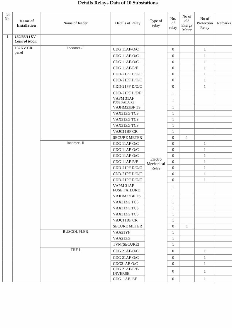
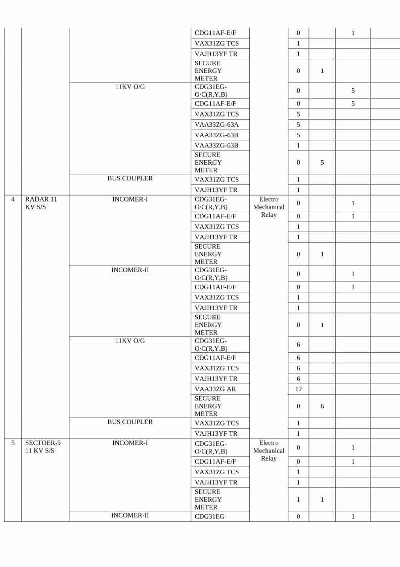
Details Relays Data of 10 Substations
Sl
No. Name of
Installation Name of feeder Details of Relay
Type of
relay
No.
of
relay
No of
old
Energy
Meter
No of
Protection
Relay
Remarks
1 132/33/11KV
Control Room
132KV CR
panel
Incomer -I CDG 11AF-O/C
Electro
Mechanical
Relay
0 1
CDG 11AF-O/C 0 1
CDG 11AF-O/C 0 1
CDG 11AF-E/F 0 1
CDD-21PF D/O/C 0 1
CDD-21PF D/O/C 0 1
CDD-21PF D/O/C 0 1
CDD-21PF D/E/F 1
VAPM 31AF FUSE FAILURE
1
VAJHM23BF TS 1
VAX31ZG TCS 1
VAX31ZG TCS 1
VAX31ZG TCS 1
VAJC11BF CR 1
SECURE METER 0 1
Incomer -II CDG 11AF-O/C 0 1
CDG 11AF-O/C 0 1
CDG 11AF-O/C 0 1
CDG 11AF-E/F 0 1
CDD-21PF D/O/C 0 1
CDD-21PF D/O/C 0 1
CDD-21PF D/O/C 0 1
VAPM 31AF
FUSE FAILURE 1
VAJHM23BF TS 1
VAX31ZG TCS 1
VAX31ZG TCS 1
VAX31ZG TCS 1
VAJC11BF CR 1
SECURE METER 0 1
BUSCOUPLER VAA21YF 1
VAA21ZG 1
TVM(SECURE) 1
TRF-I CDG 21AF-O/C 0 1
CDG 21AF-O/C 0 1
CDG21AF-O/C 0 1
CDG 21AF-E/F-
INVERSE 0 1
CDG11AF- EF 0 1

CAG 14AF-REF 0 1
VAA33ZG AR 5
DTH-31 DIFF. 1
VAX31ZG TCS 3
VAZHM23BF12D 1
VAZC11BF CR 1
TRF-II CDG 21AF-O/C 0 1
CDG 21AF-O/C 0 1
CDG21AF-O/C 0 1
CDG 21AF-E/F-
INVERSE 0 1
CDG11AF- EF 0 1
CAG 14AF-REF 0 1
VAA33ZG AR 5
DTH-31 DIFF. 1
VAX31ZG TCS 3
VAZC11BF CR 1
VAZHM23BF12D 1
TRF-III (New) 7UT613
SIPROTECH NUMERIC
RELAY
1
7SR 1
AX.RELAY Electro
Mechanical
Relay
8
TSR1MYN 2
RXMV2 1
MFM METER 1
33 KV
PANEL
BOARD
INCOMER -I (NEW)(P-11) CDG 31EG -
O/C(R,Y,B)
Electro
Mechanical
Relay
0 1
CDG11AF-E/F 0 1
CDG12-SE/F 0 1
CAG14AF-IE/F 0 1
VAA11YF AR 3
VAX31ZG TCR 1
VAJC11BF CR 1
VAJHM23BF ZG
MT 1
ENERGY
METER 0 1
INCOMER -II(P-6) CDG 31EG -
O/C(R,Y,B) 0 1
CDG11AF-E/F 0 1
CDG12-SE/F 0 1
CAG14AF-IE/F 0 1
VAA11YF AR 3
VAX31ZG TCR 1
VAJC11BF CR 1
VAJHM23BF ZG
MT 1
ENERGY
METER 0 1
INCOMER -III(P-24) MI COM 122
NUMERIC
RELAY 1

MI COM 120 NUMERIC
RELAY 1
1MYN56 MTR Electro
Mechanical
Relay
1
TCS1MYN 1
SECURE
ENERGY
METER
1
33KVOG(OLD) P- 1,5,12,16) CDG 31EG-
O/C(R,Y,B)
Electro
Mechanical
Relay
4 4
CDG 11AF-E/F 0 4
VAJC11AF CR 4
VAA11YF 12
VAJH23ZG 4
VAX31ZG 4
SECURE
ENERGY
METER
0 4
HORN4 RF 8
33KVOG TRf(OLD)(P-2,4,13,14) CDG 31EG-
O/C(R,Y,B) 0 4
CAG14AF-E/F 0 4
MBCH 12D1AB
DIFF 12
VAA11YF AR 12
VAX31ZG 4
VAJH23ZG MT 4
VAJC11BF CR 4
VAX13ZG AR 4
ENERGY
METER 0 4
33KVOG(NEW) P-17,22,23 MI COM 122 NUMERIC RELAY
3
HORN4 6
TCSYMYN Electro
Mechanical
Relay
3
1MYN56
RELAY 3
SECURE
ENERGY
METER
0 3
33KVOG TRF P-21,20 (NEW) MI COM 122 NUMERIC
RELAY
3
DTH31FF DIFF 3
YMYN56 AR Electro
Mechanical
Relay
6
TCSMYN56
RELAY 3
SECURE
ENERGY
METER
0 3
11KV VCB
PANEL
INCOMER -I ,II,III,IV,V (NEW) MICOM P-127 NUMERIC
RELAY 5
YMYN56 AR Electro
Mechanical Relay
5
TCSMYN56
RELAY 5
SECURE
ENERGY
METER
PREMERE-300
0 5

INCOMER-VI (OLD) CDG 31EG-O/C
&EF Electro
Mechanical
Relay
0 3
VAJH13YF 1
ENEGRY
METER 0 1
11KVOG(NEW) P-
2,3,4,8,9,10,14,15,16,20,21,22,27,28,&29. MICOM P-122
NUMERIC
RELAY 15
YMYN56 AR Electro
Mechanical
Relay
15
TCSYM 56 15
SECURE
ENERGY
METER
PREMERE-300
0 15
11KVOG(OLD)(P-1,31) ABB-RED616
NUMERIC
RELAY 1
11KVOG(OLD)(P-32) CDG 31EG-O/C
&EF Electro
Mechanical
Relay
0 1
CDG-R/F 0 1
2 MADHUBAN
11KV S/S
INCOMER-I CDG31EG-
O/C(R,Y,B)
Electro
Mechanical
Relay
0 1
CDG11AF-E/F 0 1
VAX31ZG TCS 1
VAJH13YF TR 1
SECURE
ENERGY
METER
0 1
INCOMER-II CDG31EG-
O/C(R,Y,B) 0 1
CDG11AF-E/F 0 1
VAX31ZG TCS 1
VAJH13YF TR 1
SECURE
ENERGY
METER
0 1
11KV O/G(8 No) CDG31EG-
O/C(R,Y,B) 0 8
CDG11AE-E/F 0 8
VAX31ZG TCS 8
VAA33ZG AR 16
VAJH13YF TR 8
SECURE
ENERGY
METER
0 8
BUS COUPLER VAX31ZG-TCS 1
VAJH13YF-TR 1
3 NAC 11KV
S/S
INCOMER-I CDG31EG-
O/C(R,Y,B)
Electro
Mechanical
Relay
0 1
CDG11AF-E/F 0 1
VAX31ZG TCS 1
VAJH13YF TR 1
SECURE
ENERGY
METER
0 1
INCOMER-II CDG31EG-
O/C(R,Y,B) 0 1
CDG11AF-E/F 0 1
VAX31ZG TCS 1
VAJH13YF TR 1
SECURE
ENERGY
METER
0 1
11KV O/G CDG31EG-
O/C(R,Y,B) 0 5
CDG11AF-E/F 0 5
VAX31ZG TCS 5
VAA33ZG-63A 5
VAA33ZG-63B 5
VAA33ZG-63B 1
SECURE
ENERGY
METER
0 5
BUS COUPLER VAX31ZG TCS 1
VAJH13YF TR 1
4 RADAR 11
KV S/S
INCOMER-I CDG31EG-
O/C(R,Y,B)
Electro
Mechanical
Relay
0 1
CDG11AF-E/F 0 1
VAX31ZG TCS 1
VAJH13YF TR 1
SECURE
ENERGY
METER
0 1
INCOMER-II CDG31EG-
O/C(R,Y,B) 0 1
CDG11AF-E/F 0 1
VAX31ZG TCS 1
VAJH13YF TR 1
SECURE
ENERGY
METER
0 1
11KV O/G CDG31EG-
O/C(R,Y,B) 6
CDG11AF-E/F 6
VAX31ZG TCS 6
VAJH13YF TR 6
VAA33ZG AR 12
SECURE
ENERGY
METER
0 6
BUS COUPLER VAX31ZG TCS 1
VAJH13YF TR 1
5 SECTOER-9
11 KV S/S
INCOMER-I CDG31EG-
O/C(R,Y,B)
Electro
Mechanical
Relay
0 1
CDG11AF-E/F 0 1
VAX31ZG TCS 1
VAJH13YF TR 1
SECURE
ENERGY
METER
1 1
INCOMER-II CDG31EG- 0 1

O/C(R,Y,B)
CDG11AF-E/F 0 1
VAX31ZG TCS 1
VAJH13YF TR 1
SECURE
ENERGY
METER
0 1
11KV O/G CDG31EG-
O/C(R,Y,B) 0 6
CDG11AF-E/F 0 6
VAX31ZG TCS 6
VAJH13YF TR 6
VAA33ZG AR 12
SECURE
ENERGY
METER
0 6
BUSCOUPLER VAX31ZG TCS 1
VAJH13YF TR 1
6 V-POINT
11KV S/S
INCOMER-I CDG31EG-
O/C(R,Y,B)
Electro
Mechanical
Relay
0 1
VAJH13YF-TR 1
ENERGY
METER 0 1
INCOMER-II CDG31EG-
O/C(R,Y,B) 0 1
VAJH13YF-TR 1
ENERGY
METER 0 1
11KV O/G CDG31EG-
O/C(R,Y,B) 0 6
CDG11AE-E/F 0 6
VAX31ZG TCS 6
VAA33ZG AR 6
VAJH13YF TR 6
ENERGY
METER 0 6
7 CCT 11KV
S/S
INCOMER-I (NEW) MI COM P-141
NUMERIC
RELAY
1
SeCURE
ENERGY
METER
0 1
INCOMER-II (NEW) MI COM P-141 1
SeCURE
ENERGY
METER
1
11KV O/G MI COM P-141 6
SeCURE
ENERGY
METER
0 6
8 BOT 33 KV
S/S
INCOMER-I (NEW) MI COM P-120
NUMERIC
RELAY
1
MI COM P-122 1
SeCURE
ENERGY
METER
0 1
INCOMER-II (NEW) MI COM P-120 1
MI COM P-122 1

SeCURE
ENERGY
METER
0 1
33KVOG(NEW) MI COM 122-O/C 4
SeCURE
ENERGY
METER
0 4
33KV TRF(NEW) MI COM 122-O/C 1
OTI-CV202J Electro
Mechanical
Relay
1
WTI-CV202J 1
BUCHHLOZ -
CV202J 1
SeCURE
ENERGY
METER
0 1
9 IOHP 11 KV
S/S
INCOMER-I CDG31EG-
O/C(R,Y,B)
Electro
Mechanical
Relay
0 1
CDG11AF-IE/F 0 1
CDG12AF-SE/F 0 1
VAJC11BF CR 1
VAX31ZG TCS 1
VAJH13YF TR 1
VAG11YF NVC 1
ENERGY
METER 0 1
INCOMER-II CDG31EG-
O/C(R,Y,B) 0 1
CDG11AF-IE/F 0 1
CDG12AF-SE/F 0 1
VAJC11BF CR 1
VAX31ZG TCS 1
VAJH13YF TR 1
VAG11YF NVC 1
ENERGY
METER 0 1
11KV O/G CDG31EG-
O/C(R,Y,B) 0 8
CDG11AF-IE/F 0 8
VAJC11BF CR 8
VAX31ZG TCS 8
VAJH13YF TR 8
ENERGY
METER 0 8
BUS TRANSFER CDG31EG-
O/C(R,Y,B) 0 1
CDG17AF-IE/F 0 1
VAJC11BF CR 1
VAA33JG (T/A)
AR 2
VAX31ZG TCS 1
VAJH13YF TR 1
BUS COUPLER VAJC11BF CR 1
VAX31ZG TCS 1
VAJH13YF TR 1

10 HARBOUR
33/11 KV S/S
INCOMER-I CDG31EG-
O/C(R,Y,B)
Electro
Mechanical
Relay
0 1
CDG11AF-IE/F 0 1
CDG12AF-SE/F 0 1
VAJC11BF CR 1
VAX31ZG TCS 1
VAJH13YF TR 1
VAPM31AF21A
FFR 1
VAG11YF NVC 1
ENERGY
METER 0 1
INCOMER-II CDG31EG-
O/C(R,Y,B) 0 1
CDG11AF-IE/F 0 1
CDG12AF-SE/F 0 1
VAJC11BF CR 1
VAX31ZG TCS 1
VAJH13YF TR 1
VAPM31AF21A
FFR 1
VAG11YF NVC 1
ENERGY
METER 0 1
33KV TRF CDG31EG-
O/C(R,Y,B) 0 1
CDG12ZF-SE/F 0 1
VAJC11BF CR 1
VAA23ZG AR 1
VAA33ZG AR 2
VAX31ZG TCS 1
VAJH13YF TR 1
33KV TRF CDG31EG-
O/C(R,Y,B) 1
CDG12ZF-SE/F 1
VAJC11BF CR 1
VAA23ZG AR 1
VAA33ZG AR 2
VAX31ZG TCS 1
VAJH13YF TR 1
BUS COUPLER VAJC11BF CR 1
VAX31ZG TCS 1
HARBOUR
11 KV S/S
INCOMER-I CDG31EG-
O/C(R,Y,B) 0 1
CDG11AF-IE/F 0 1
CDG12AF-SE/F 0 1
VAJC11BF CR 1
VAX31ZG TCS 1
VAJH13YF TR 1
ENERGY
METER 0 1
INCOMER-II CDG31EG- 0 1

O/C(R,Y,B)
CDG11AF-IE/F 0 1
CDG12AF-SE/F 0 1
VAJC11BF CR 1
VAX31ZG TCS 1
VAJH13YF TR 1
ENERGY
METER 0 1
11KV O/G CDG31EG-
O/C(R,Y,B) 0 8
CDG11AF-IE/F 0 8
VAJC11BF CR 8
VAX31ZG TCS 8
VAJH13YF TR 8
ENERGY
METER 8 1
11KV TRF CDG31EG-
O/C(R,Y,B) 0 1
CDG17AF-IE/F 0 1
VAJC11BF CR 1
VAX33ZG TCS 1
VAJH13YF TR 1
VAA33ZG(A/T)
AR 2
ENERGY
METER 0 1
BUS COUPLER VAJC11BF CR 1
VAX31ZG TCS 1
VAJH13YF TR 1
TOTAL 523 110 179