Embed Size (px)
Citation preview
Page 1 of 23
Request for Proposal – 2015 FRC® Control System
Contents 1.2. FIRST® Robotics Competition Overview .................................................................. 3
3. Project Overview ...................................................................................................... 3 4. Schedule .................................................................................................................. 3 5. Project Requirements ............................................................................................... 4
5.1 Manufacturing .................................................................................................... 4 5.2 Software/Firmware support ................................................................................ 4
5.3 Sales .................................................................................................................. 4 5.4 Technical Support/Documentation ..................................................................... 5
6. General RCS Requirements .................................................................................... 5 6.1 Safety ................................................................................................................. 7 6.2 User Experience ................................................................................................. 7
6.2.1 Complexity / Integration Level ..................................................................... 7
6.2.2 Simplicity of setup ........................................................................................ 8 6.2.3 Documentation and User Resources ........................................................... 8
6.2.4 Technical System Diagnostics ..................................................................... 8 6.3 Robustness ........................................................................................................ 9 6.4 Environmental .................................................................................................... 9
6.5 Mechanical ......................................................................................................... 9 6.6 Electrical ............................................................................................................ 9
6.7 Electro-Magnetic Interference ............................................................................ 9
6.8 User-Programming Language Support ............................................................ 10
6.9 RCS-Field Management System (FMS) Interface ............................................ 10 6.10 RCS Volume Requirements .......................................................................... 11
6.11 RCS Costing ................................................................................................. 11 7. RCS Component Specific Requirements ............................................................... 12
7.1 DS Feature Set ................................................................................................ 12
7.2 MRC Feature Set ............................................................................................. 13 7.3 Wireless Robot Control (WRC) Feature Set ..................................................... 14
7.4 Power Distribution Feature Set ........................................................................ 15 7.5 Motor Control Module (MCM) Feature Set ....................................................... 15
7.6 Vision Feature Set ............................................................................................ 16 8. Ownership of Materials .......................................................................................... 16 9. Proposal Elements ................................................................................................. 16
9.1 Cover Page ...................................................................................................... 17 9.2 Transmittal Letter ............................................................................................. 17 9.3 Section I – Executive Summary ....................................................................... 17 9.4 Section II – General Company Information ...................................................... 17
9.5 Section III – Technical Commitments ............................................................... 18 9.6 Section IV – Management Section ................................................................... 18 9.7 Section V – Supplier References ..................................................................... 18 9.8 Section VI – Additional Information .................................................................. 18 9.9 Section VII - Pricing .......................................................................................... 18
Page 2 of 23
10. Proposal Costs ....................................................................................................... 19
11. Available Project Resources .................................................................................. 19 12. Recognition Opportunities ...................................................................................... 19
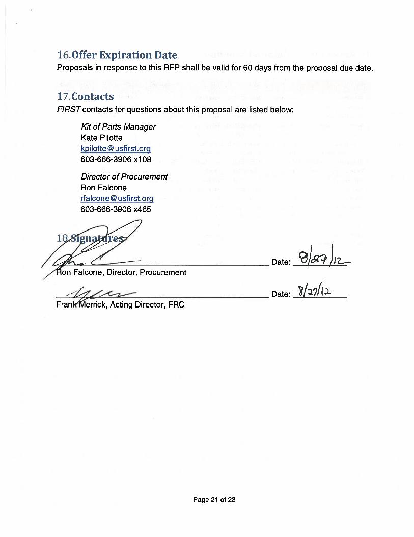
13. Proposal Evaluation Criteria ................................................................................... 19 14. Non-Disclosure....................................................................................................... 20 15. RFP Amendments .................................................................................................. 20 16. Offer Expiration Date .............................................................................................. 20 17. Contacts ................................................................................................................. 21
18. Signatures .............................................................................................................. 21 19. Appendix A - Detailed Schedule............................................................................. 22 20. Appendix B – Acronym Listing ............................................................................... 23
Page 3 of 23
FIRST® Robotics Competition Overview 2.The FIRST Robotics Competition, FRC®, is a unique varsity Sport for the Mind™
designed to help high-school-aged young people discover how interesting and
rewarding the lives of engineers and scientists can be. FRC stages short games played
by robots. The robots are designed and built in a limited time frame (from a common set
of parts) by a team of high-school-aged young people and Mentors. FRC teams
program and remotely control the robots in competition rounds on a competition field.
Teams are formed in the fall. The annual FRC Kickoff in early January starts the short
“build” season. Competitions take place in March and April. FRC Regional events are
typically held in arenas. They involve 40 to 70 teams cheered by thousands of fans over
three days. A championship event caps the season. Referees oversee the competition.
Judges evaluate teams and present awards for design, technology, sportsmanship, and
commitment to FIRST. The Chairman’s Award is the highest honor at FIRST and
recognizes a team that exemplifies the values of FIRST.
Project Overview 3.The current FRC control system is a custom configuration of devices from various
suppliers used by teams to program and wirelessly control actuators and sensors on
their robots. Details about the 2012 FRC control system are hosted on the FIRST
website here.
The current control system, to be used through the 2014 season, is based on Ethernet
and PWM protocols, but can also accommodate CAN, SPI, and I2C.
Given the end-of-life nature of the existing system, FIRST is searching for solutions and
a partner, or suite of partners, with which to implement such solutions for the 2015 -
2019 seasons. This document outlines the requirements and preferences for such a
system.
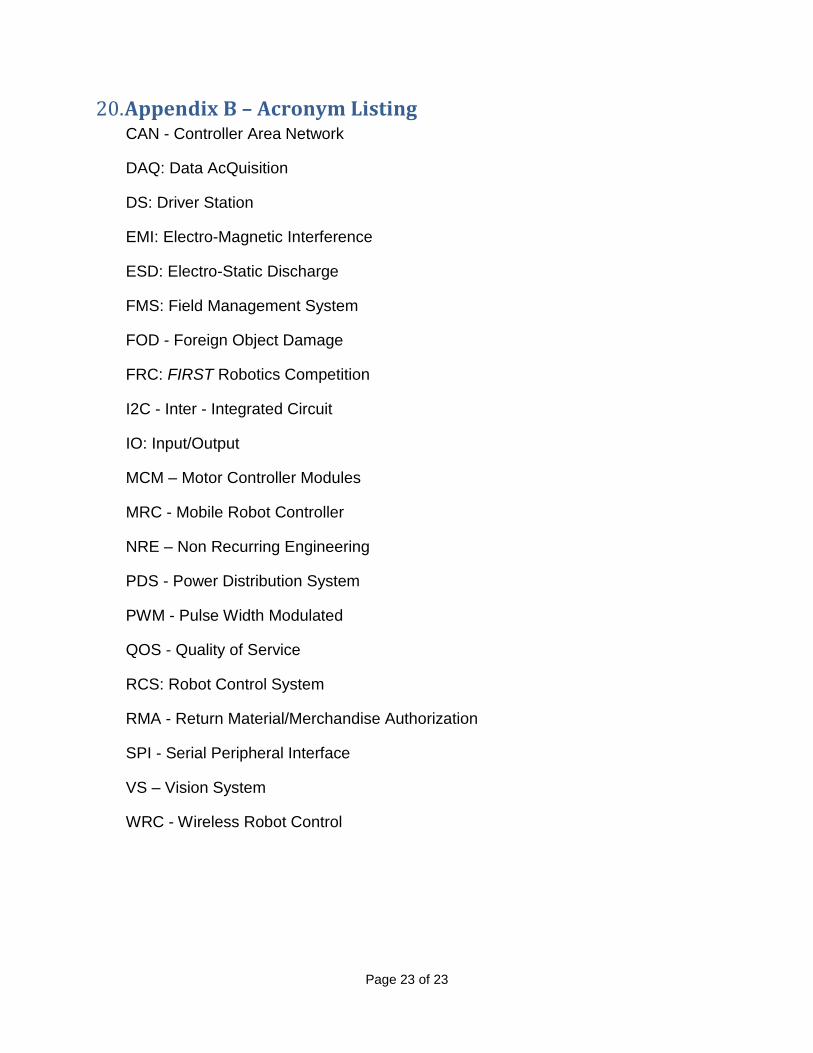
RFP specific terms and acronyms are defined in Appendix B – Acronym Listing.
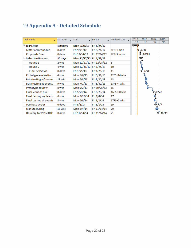
Schedule 4.The immediate proposal-specific timeline for the 2015 FRC Control System project is
outlined below. A detailed proposed schedule for efforts leading up to the 2015 season
is included in Appendix A - Detailed Schedule. Respondents are encouraged to include
added detail or proposed adjustments as required by their business models, as well as
a general schedule to support all five seasons of the proposal.
RFP published/distributed: August 28, 2012
Page 4 of 23
Letters of Intent due to FIRST: September 21, 2012
Proposals due to FIRST: December 14, 2012
Selection Progress, Round 1: December 28, 2012
Selection Progress, Final Selection: January 25, 2013
Project Requirements 5.FIRST needs a partner that will develop and support a system per the team populations
expected below.
2015: 3,600
2016: 4,000
2017: 4,700
2018: 5,400
2019: 6,200
5.1 Manufacturing
Any and all manufacturing efforts must include NRE efforts, material sourcing,
production, testing, and quality assurance.
This effort also requires the back-end support for RMAs and warranty support.
5.2 Software/Firmware support
FIRST needs a partner that can recommend, execute, test, and support any firmware or
software changes needed to support the next-generation control system.
5.3 Sales
To comprehensively support team competition needs, all components must be available
to teams for purchase in the event that a team needs additional devices for their
designs, replacements for damaged units, or spare inventory. FIRST does not host a
store front to accommodate this and needs a partner that can own inventory, house
inventory, host a store front, and process orders in a timely manner (shipping within, at
most, two days of a placed order).
Sales may or may not require a passive royalty paid to FIRST to be mutually agreed
upon by all parties affected.
Page 5 of 23
5.4 Technical Support/Documentation
FIRST is seeking a partner that can provide Robot Control System (RCS) technical
support for both FRC and FRC teams. A preferred support structure includes the
following components:
a) development support for FIRST for any changes required for hardware, firmware,
or software
b) support for incorporating any changes into the FRC software libraries
c) support for manufacturing efforts (approval of alternate components, updates to
relevant files, etc.)
d) support for FRC teams
i. updates to documentation that provide clean, concise instruction and
information
ii. accessibility for teams that needed additional help via phone, forum, email
(preferably all)
e) Presence at FRC events for triage and technical support during competitions
A product warranty with rapid replacement for critical components during the build
season is required.
General RCS Requirements 6.There are a number of considerations for the next generation RCS that must be
addressed in any proposal. The overall objective is to provide a challenging and
satisfying experience to for FRC teams. Generally, the FRC desires to minimize the
following parameters:
a) system complexity (wiring, etc.)
b) user set up time (2-3 hours maximum)
c) cost
d) size
e) fragility
With every system, there are tradeoffs which must be made; to that end, the following
criteria are detailed in this document to elaborate on FRC’s priorities and expectations
for a comprehensive proposal.
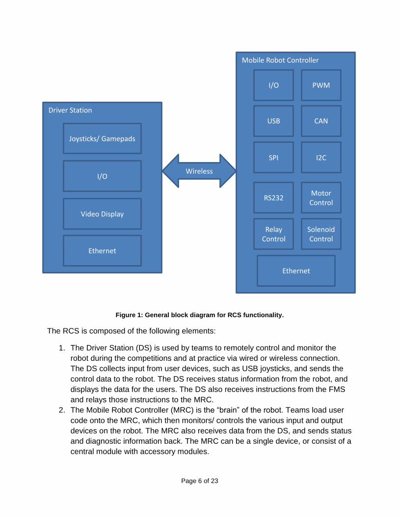
The RCS shall function in accordance with the top-level block diagram illustrated below
in Figure 1.
Page 6 of 23
Figure 1: General block diagram for RCS functionality.
The RCS is composed of the following elements:
1. The Driver Station (DS) is used by teams to remotely control and monitor the
robot during the competitions and at practice via wired or wireless connection.
The DS collects input from user devices, such as USB joysticks, and sends the
control data to the robot. The DS receives status information from the robot, and
displays the data for the users. The DS also receives instructions from the FMS
and relays those instructions to the MRC.
2. The Mobile Robot Controller (MRC) is the “brain” of the robot. Teams load user
code onto the MRC, which then monitors/ controls the various input and output
devices on the robot. The MRC also receives data from the DS, and sends status
and diagnostic information back. The MRC can be a single device, or consist of a
central module with accessory modules.
Driver Station
Joysticks/ Gamepads
I/O
Video Display
Mobile Robot Controller
PWM
USB
Wireless
I/O
CAN
I2C SPI
RS232 Motor Control
Relay Control
Solenoid Control
Ethernet
Ethernet
Page 7 of 23
3. Secondary Components provide additional modules in the robot control system,
including devices to provide power distribution and wireless communication. The
functionality of these modules may be integrated into the MRC, but is not
required.
4. Wireless Robot Control (WRC) modules facilitate wireless communication
between the DS and the MRC over a secure network – both “at home” and at
competition events. The wireless functionality may be integrated into the system
or as a separate component.
5. The RCS components on the robot accommodate a main 12V sealed lead acid
battery power source.
6. The RCS supports camera/vision.
7. All devices must have mounting points for securing to the robot.
8. The overall boot time for the system, from cold boot to wirelessly connected
(assuming an at-home configuration) shall be minimized, but shall not exceed 40
seconds. Individual boot times for individual component shall be minimized.
6.1 Safety
Safety must be foremost in the design and operation of all aspects of the RCS.
Safety features must prevent all run-away conditions. The most basic level of safety for
every system level is to prevent robot operation in the event of loss of communications.
Redundancy at both the top system level and the power module levels (motor
controllers, relays, etc.) is preferred.
Basic timeout failsafe features are required (in the event of locked code, etc.), and users
must be able to enable and disable device operation on their robot from their DS. These
safety features must not be able to be disabled by the user and should be “built into” the
modules in a secure manner. The user should be clearly informed when a safety system
is engaged.
6.2 User Experience
FRC teams present a wide range of technical capacity with diverse backgrounds. It is
important for the RCS to provide intuitive interfaces and streamlined setup for users.
Features promoting system convenience, e.g. the user may deploy code via a wireless
interface, are encouraged.
6.2.1 Complexity / Integration Level
The RCS design should aim for minimal module counts for basic robot operation. Basic
robot operation includes the following: DS, MRC, 4-motor variable speed/direction
control, I/O, WRC, Relay, Vision, and all supporting power distribution. The MRC must
be simple to wire and configure with an intuitive user setup. The MRC must provide
expansion capacity and flexibility for FRC teams.
Page 8 of 23
6.2.2 Simplicity of setup
A user should be able to configure the RCS components for use in 45 minutes or less.
This setup time includes:
1. Firmware/software upgrade on the MRC.
2. Configuration of any team-specific settings on the MRC.
3. Compilation and download of default code to the MRC.
4. Firmware/software upgrade on the DS.
5. Configuration of any team-specific settings on the DS.
The purpose of this requirement is to provide teams with the ability to quickly verify the
RCS operation and to enable programming teams to start with a working electrical
control system.
The RCS must provide for programming and image updates that are non-bricking and
can be recovered via a factory settings reset.
6.2.3 Documentation and User Resources
The submission must include a proposed portfolio for comprehensive, yet concise
information dissemination to teams. Content shall include, but not necessarily be limited
to device specifications, a quick-start guide, a detailed user guide, etc.
A strong bias toward graphical information representation is encouraged. Information
distribution that accommodates teams with all levels of resources is crucial, but
assumption that each team has access to a computer and the internet is appropriate.
Information distributed by additional methods (smart phone app, etc.) are encouraged.
6.2.4 Technical System Diagnostics
The RCS must have diagnostics to aid in both system setup and troubleshooting. At the
system level, a diagnostics system that maps the connected system and reporting
missing components or failed modules is preferred.
The module level diagnostics should include the ability to verify basic operation and
configuration of the various modules including software and hardware revisions. Missing
or failed modules should not cause the system to lock up, outside of safety features
noted in 6.1, Safety. The diagnostics should point the users towards modules or
connection level issues as an aid for debugging.
The RCS should also track and log, for later review, the quality of service (QOS)
information for the connection to the MRC. Live access to the QOS numbers or other
important diagnostics via the DS display is required.
Page 9 of 23
6.3 Robustness
The robot environments (at a home shop, in a team pit, and on the competition field) are
a particularly harsh environment with mechanical, electrical and environmental
conditions that stress the RCS significantly. The RCS must be designed to withstand
these conditions, assuming at least 4-5 events per season and provide multi-year
reliable service. The events are played out in 2 minute 15 sec matches with between 9
and 18 matches (including playoffs) spanning a 2-3 days. A failure of a module causing
a lost match is a negative user experience, the need to maintain the operation of the
core components of the system and logging of status is critical.
6.4 Environmental
The robots must operate under standard commercial operating conditions. Industrial
operating conditions capacity is desired as robots are operated throughout the summer
and in non-air-conditioned venues. Operation in these conditions is expected and must
not reduce the lifetime of the devices.
6.5 Mechanical
The mechanical conditions include shock, vibration, and stress due to repeated
insertion/removal of module connections. It would not be unusual for the RCS
components installed on a competition robot to experience up to 50Gs during operation
and significant vibration (including inverted falls of the robot). The modular nature of the
system facilitates swap out of components with the expectation that the connectors will
not fail nor become loose or disconnected during operation and be able to sustain
thousands of insertion/removals over the expected lifetime of the modules. RCS
modules must be protected from metal debris induced failures and come with a rugged
case.
6.6 Electrical
The electrical environment is harsh both during robot operation and assembly. Reverse
battery protection is desired to prevent damage to components due to an oversight or
miss wiring of power connections. The robots will encounter significant ESD events both
from interaction with the field and humans. ESD protection must be designed in and
tested for all devices with particular concern for IOs. Short circuit and overcurrent
protection is preferred to ensure that mis-wired, cut, or shorted lines will not damage the
module.
6.7 Electro-Magnetic Interference
The control system must be able to withstand the EMI generated by the on board DC
motors. Due to the limited space on the robot, control system components will be in
close proximity to the DC motors.
Page 10 of 23
6.8 User-Programming Language Support
The next generation RCS must support at least two programming languages (but not
require that teams use both). One language must support a graphical programming
environment (e.g. LabVIEW, EasyC). The current RCS supports LabVIEW, C++, and
Java. It is preferred that the new RCS support as many of these currently used
languages as possible. Installation and update times must be kept to a minimum for
library, language updates and for software development tool installation.
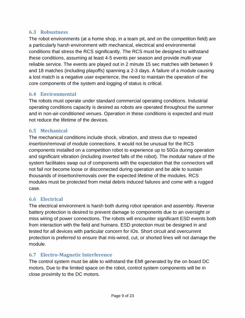
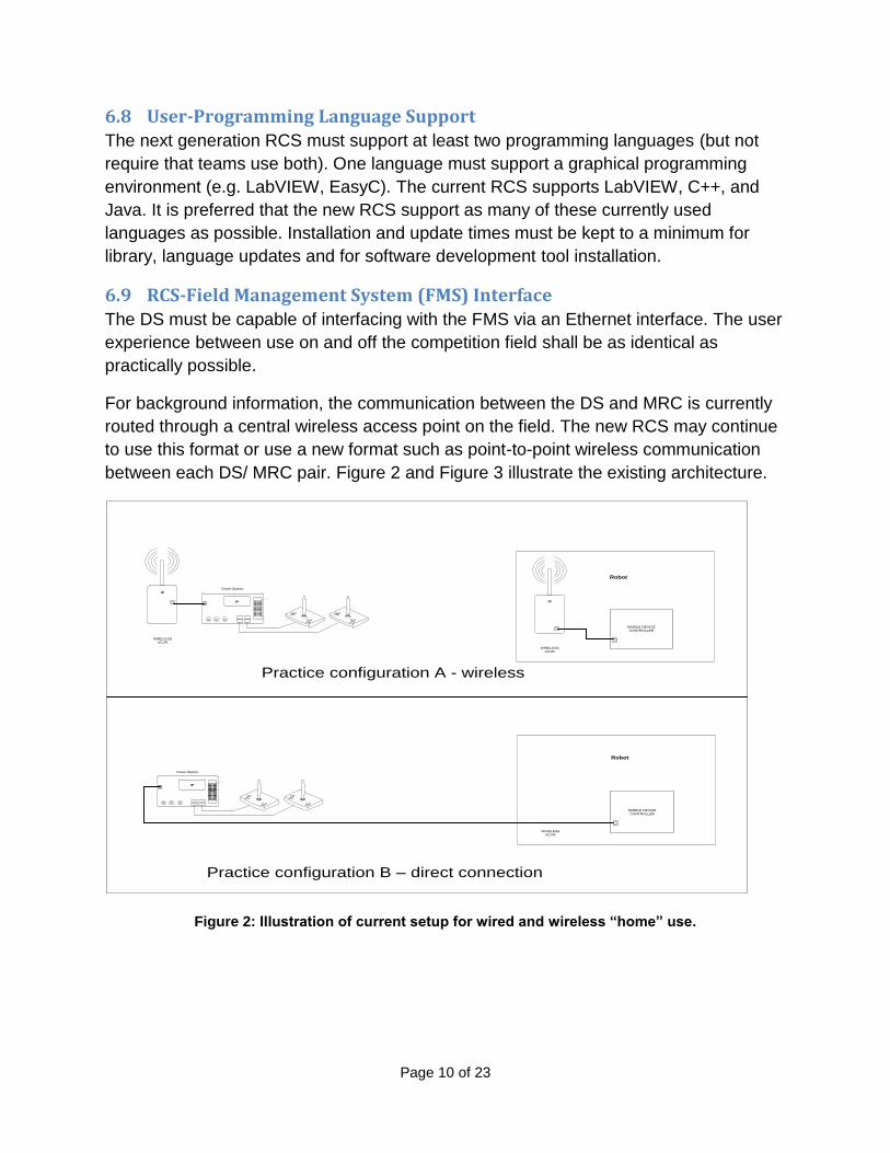
6.9 RCS-Field Management System (FMS) Interface
The DS must be capable of interfacing with the FMS via an Ethernet interface. The user
experience between use on and off the competition field shall be as identical as
practically possible.
For background information, the communication between the DS and MRC is currently
routed through a central wireless access point on the field. The new RCS may continue
to use this format or use a new format such as point-to-point wireless communication
between each DS/ MRC pair. Figure 2 and Figure 3 illustrate the existing architecture.
Driver Station
Bla
ck
RedWht/
Yel
GND+7.
2V
SIG
WIRELESS
XCVR
IP IP
Robot
MOBILE DEVICE
CONTROLLER
WIRELESS
XCVR
IP
Practice configuration A - wireless
Driver Station
Bla
ck
RedWht/
Yel
GND+7.
2V
SIG
WIRELESS
XCVR
IP
MOBILE DEVICE
CONTROLLER
Practice configuration B – direct connection
Robot
Figure 2: Illustration of current setup for wired and wireless “home” use.
Page 11 of 23
Driver Station
Bla
ck
Red
Wht/
Ye
l
GND+7
.
2V
SIG
Driver Station
Bla
ck
Red
Wht/
Ye
l
GND+7
.
2V
SIG
Driver Station
Bla
ck
Red
Wht/
Ye
l
GND+7
.
2V
SIG
DAQC
MODULE
SBC
Power
Supply
ETHERNET
TO RS422/485
ETHERNET SWITCH
BLUE SCC
Driver Station
Bla
ck
Red
Wh
t/
Ye
l
GND+7
.
2V
SIG
Driver StationB
la
ck
Red
Wh
t/
Ye
l
GND+7
.
2V
SIG
Driver Station
Bla
ck
Red
Wh
t/
Ye
l
GND+7
.
2V
SIG
DAQC
MODULE
SBC
Power
Supply
ETHERNET
TO RS422/485
ETHERNET SWITCH
RED SCC
FIELD
WIRELESS
ACCESS
POINT
WIRELESS
XCVR
IP
IP
IP
IP
IP
IP
IP
IP
IP
IP
IP
IP
IP
IP
IP
IP
BLUE BOT BLUE BOT BLUE BOT
RED BOT
MOBILE DEVICE
CONTROLLER
WIRELESS
XCVR
IP
MOBILE DEVICE
CONTROLLER
WIRELESS
XCVR
IP
MOBILE DEVICE
CONTROLLER
WIRELESS
XCVR
IP
MOBILE DEVICE
CONTROLLER
WIRELESS
XCVR
IP
MOBILE DEVICE
CONTROLLER
WIRELESS
XCVR
IP
MOBILE DEVICE
CONTROLLER
RED BOT RED BOT
Current Field Setup
Figure 3: Illustration of current field setup.
6.10 RCS Volume Requirements
The size and weight of the RCS must be kept to a minimum to ease integration onto
robot platforms and enable teams to meet the strict robot weight requirements. The
basic RCS for size and weight considerations will consist of following components: DS,
MRC, 4-motor variable speed/direction control, I/O, WRC, Relay, Vision, and all
supporting power distribution.
The combined footprint for these functional blocks should be less than 220 square
inches and no taller than 6 inches. The weight should be less than 7 lbs.
6.11 RCS Costing
The RCS is meant to be easy to implement on robots and affordable for teams. Teams
will need at least one full RCS setup while many will likely demand more than one
complete setup. The cost of the full RCS and sub-components will be a major factor
taken into account when evaluating proposals.
Target cost per system to FIRST: $0
Target cost per system to sold directly to FRC teams: $600
Page 12 of 23
There is a likely chance that FIRST, working with the Electronics Component Industry
Association, ECIA, and other Suppliers, may minimize material costs. In submitting
proposals, please itemize material costs as a separate line item. Also, the
manufacturing partner will likely need to incorporate/accommodate donated material
(but is invited to include the material commitment and due dates needed to
accommodate the manufacturing timeline). FIRST assumes that any donated
components/materials will be removed from any/all invoiced costs to FIRST.
RCS Component Specific Requirements 7.To elaborate on the general requirements from Section 6, General RCS Requirements,
component specific requirements are detailed below.
7.1 DS Feature Set
The DS provides teams with an interface for robot control and feedback. The DS will
provide user-to-robot commands in control packets and receives status and live video
back from the robot for display. Teams must be able to customize the display (adapting
the robot feedback to the game and their control/status needs). User input device
flexibility is also a requirement as teams may choose to use a wide range of joysticks,
gamepads, and specialized user interfaces. Required technical specifications for the DS
solution are listed below.
DS1. Battery operated 3-hour capacity with plug in power supply for charging.
DS2. Support for at least 4 USB 2.0 joysticks or gamepads (but not off the same
USB chip)
DS3. 8 digital IO and 4 analog inputs (in addition to USB requirements noted in
DS2), integrated or supported by external DAQ
DS4. 10/100 Ethernet
DS5. Wireless communication with robot, external or integrated
DS6. Capable of supporting video display from robot
DS7. Quick boot from power up not to exceed 30 seconds
DS8. Software to provide communications with MRC and FMS
DS9. Capability to display real-time system diagnostics, with ability for teams to
customize which data is displayed
DS10. Sufficient non-volatile storage capable of rough environment / handling to
provide user code and logging storage (“sufficient” is dependent on the
solution, but ultimately presents no perceptible delay or performance issues
to the user).
Page 13 of 23
7.2 MRC Feature Set
The MRC provides all the needed control and sensing on the robot for the teams.
Minimum requirements are listed below.
MRC1. Battery brown out protection and ride through without loss of state/reboot
MRC2. Control of actuators remains active to 6V
MRC3. Control logic remains active and not lose state to 4V
MRC4. At least 16 PWM channels available for supporting hobby servos and motor
controllers
a) capable of supporting at least 2 x 6V hobby servos (~1.1A/servo)
b) drive strength of 330 Ohms @ 5V
c) 150kHz timer resolution
MRC5. At least 18 digital I/O, with user able to add at least 10 more if needed
a) of which are dedicated for relay control (≥4mA, ≥3V)
b) 3.3V native
c) 5V compatible
d) 150kHz sampling
e) Integrated weak pull up resistors.
MRC6. Able to drive at least 4, 8 preferred, pneumatic solenoid valves with 500mA
minimum, 24V (12V and 24V preferred, but not required)
a) At least 4 analog inputs, with user able to add at least 8 more if
needed
b) 10 bit or higher resolution
c) sampling at 250 kS/s
d) 0V to 5V
MRC7. USB 2.0 host port
MRC8. Support for Ethernet 10/100 devices
MRC9. Overall target for system latency of 10ms joystick to motor controller
command under typical communication conditions (assumptions include
running system in “home” configuration and running default code).
MRC10. Onboard non-volatile storage sufficient for storing user code and logging
data (up to 3 event-days) with no perceptible performance issues by the
user
MRC11. Ability for user to remove storage is preferred, but not required.
MRC12. Self-diagnostics with reporting of device status and failure modes to DS.
MRC13. Diagnostic tool for basic robot state (power, connected) viewable from at
least 50 feet.
MRC14. A display providing basic diagnostics is preferred, but not required.
Examples of such diagnostics include, but are not limited to:
a) team number,
b) IP address;
Page 14 of 23
c) Link status
d) Enable disable state
e) Teleoperated/autonomous state
f) Common error codes
MRC15. CAN 2.0B
MRC16. I2C Master
a) V2.1 compliant
b) 100kbits/s into 400pF bus load
MRC17. SPI Master
a) 100kbits/s minimum
b) Drives minimum of 4 devices
MRC18. RS232
a) 115200 baud
b) No arbitration signals necessary
MRC19. Preferred but not required support for 3D-Gyroscope and 3D-Accelerometer
7.3 Wireless Robot Control (WRC) Feature Set
This feature set is derived based on experience during the 2009, 2010, 2011, and 2012
FRC competition seasons. To date, the best performing radio has been the Linksys
WGA600N. An ideal radio would have all the features of the WGA600N, as well as
include the capability to function as an access point, and have a four port 10/100
Ethernet switch.
Other radios used/tested:
- Linksys WET610N (2010 season), - Dlink DAP-1522 (2011 & 2012 seasons), and - Linksys WES610N - Dlink DIR-825 running DD-WRT firmware
WRC1. Capable of controlling 4 co-located active fields with up to 6 robots on each field.
WRC2. <15ms latency
WRC3. Secured communication, 128-bit with no known breaks.
WRC4. Automated setup for competitions and at home use.
WRC5. Boot and acquisition within 20 seconds.
WRC6. Locking / secured power connection
WRC7. Communication QoS reported and recorded from each member in the
network.
WRC8. Reliable, robust functionality in hostile wireless environments (> 150 other
access points, cell phones, etc.)
WRC9. Target size approximately 5” x 6” x 2.”
Page 15 of 23
WRC10. Factory/initial default setup recovery required (via external but protected
button)
WRC11. Wireless module must remain active to an robot supply battery voltage of
4.5V. A dedicated power supply for the radio is preferred (to protect
diagnostic information/tools in the event of a robot power outage).
WRC12. Data logging in the device is preferred.
7.4 Power Distribution Feature Set
PD1. Stand alone, rugged On/Off switch able to be mounted in accessible spot on
the robot, likely a separate device.
PD2. Power distribution system providing 120A main supply protection.
PD3. Multi-channel power distribution board with configurable current limiting per
channel (via fuse, breaker, etc.)
PD4. At least 16 12V channels (beyond what is required by RCS components), 20
are preferred. At least 8 capable of 40A continuous, nominal.
PD5. The PDS should provide secondary voltage supplies as needed, including,
but not limited to:
PD6. 3.3V supply
PD7. 5V +/- 5%, regulated, for custom logic circuits
PD8. 24V for pneumatic solenoid valves, et al
PD9. Power budget and current logging capacity preferred, but not required.
PD10. Regulated supplies for the MRC and WRC (unless built-in to MRC and
WRC devices)
7.5 Motor Control Module (MCM) Feature Set
MCM1. Compatibility with Victor and Jaguar motor controllers is required (use of
any/all of these controllers in the RCS solution proposal is acceptable even
if they don’t meet all requirements outlined here).
MCM2. Any new controller must have a safety shut off to prevent catastrophic
failure. Such an event must be communicated to the user.
MCM3. Full H-bridge motor controller forward/reverse; capable of 60A continuous
operation (100A burst 2.5 sec).
MCM4. Motor controller must provide EMI suppression from the motor(s) via optical
isolation or comparable buffer.
MCM5. Low voltage (6V) brownout state preservation is preferred, but not required.
MCM6. If 3-pin analog interface, a ground-power-signal convention is preferred
MCM7. If proposing a “smart” motor controllers (non-PWM), controller must have:
a) current limiting,
b) voltage control,
c) PID features with analog input,
d) 0-5V quadrature encoder support,
Page 16 of 23
e) forward/reverse limit switch support
f) (preferred) robust daisy chain capability
MCM8. Linear output is preferred, but not required.
MCM9. If the user is expected to update device firmware, a common interface shall
be used.
MCM10. Simple, complete error code indication and short-term storage is preferred
MCM11. Safe dissipation of motor generated voltages and currents when power off
and motor is mechanically driven is required.
7.6 Vision Feature Set
V1. Capable of 30 Frames Per Second
V2. Capable of color
V3. Must be capable of a 320x240 resolution (higher resolution as a user option
is acceptable)
V4. RCS must support at least 1 camera; support for 2 cameras is preferred.
V5. Vision processing either on MRC, in camera, or DS is required. User ability
to use their co-processor is preferred, but not required.
V6. Cold boot to operation in less than 20 sec is desired
V7. User ability to turn off auto settings in the vision device(s) is preferred (i.e.
manually set/fix white balance and exposure).
Ownership of Materials 8.All materials submitted in response to this RFP shall become the property of FIRST.
Proposals and supporting materials will not be returned to suppliers.
Proposal Elements 9.Respondents to this Request for Proposals, RFP, have the option of bidding on all
requirements outlined in this document alone, with a suite of partners, or one or more
subsets defined below, as they feel appropriate per their business model.
Supplier Letters of Intent to Bid shall be sent to Kate Pilotte, [email protected], no
later than September 21, 2012.
Proposals are due by December 14, 2012 and must accommodate the following layout
and content:
Page 17 of 23
9.1 Cover Page
9.2 Transmittal Letter
The supplier shall prepare a brief transmittal letter on their business stationery with a
company logo. The transmittal letter should provide all of the following:
a) The supplier’s legal company name and addresses for the office submitting
the proposal as well as the address of the company’s legal headquarters.
b) A statement that the person signing this proposal is authorized to make
decisions towards the proposal and the prices quoted.
c) The name, title and telephone numbers of the persons authorized to negotiate
the contract on behalf of the organization.
d) The names, title and telephone numbers of persons to be contacted for
clarification of the proposal if needed.
9.3 Section I – Executive Summary
The executive summary shall serve to familiarize FIRST executives and evaluators
with the key elements and unique features of your proposal by briefly describing
what you are proposing to do and how you intend to accomplish the work.
The executive summary shall contain the following:
a) A summary of your approach to the project, including the main points of all
sections. Material should include the business features that make your
proposal attractive and different.
b) A master milestone schedule of all major efforts to be undertaken in the
project. Dates shall begin as listed in Section 4 of this RFP.
c) A list of exceptions taken against this RFP and the reason these exceptions
were taken. If an alternative solution or product is being proposed, it should
be briefly described.
9.4 Section II – General Company Information
a) Full legal company name.
b) Year business started.
c) State of incorporation or headquarters.
d) Are you a United States corporation?
e) Tax identification number.
f) Brief company history.
g) Current number of employees.
h) Are you a public or private corporation?
Page 18 of 23
i) Is your company currently involved in any litigation in which an adverse
decision might result in a material change in the company’s financial position
or future viability?
j) Most recent annual audited company financial report or public annual report.
9.5 Section III – Technical Commitments
The technical component of the proposal shall address the requirements listed in
this document. Responses shall indicate the specifications they intend to preserve,
as well as any they propose to modify. If modifications are proposed, this section
must include detail regarding any proposed modifications.
9.6 Section IV – Management Section
In this section, the supplier shall provide information organized into the following
sections.
a) Project Management. Suppliers shall present their company’s approach and
ability to provide experienced project managers and resources to successfully
execute this project.
b) Maintenance. Supplier shall provide a detailed description of all maintenance
activities, daily or monthly support activities and principal period of
maintenance.
c) Education and Training. Supplier shall provide a detailed description of all
education and training required for this project.
9.7 Section V – Supplier References
Suppliers shall include a minimum of three references where related contracts have
been awarded within the last three years.
9.8 Section VI – Additional Information
Suppliers may submit additional information that is relevant but was not requested in
the RFP. This information should clarify or enhance the proposal or provide
information about areas in the RFP that are deficient and need to be corrected.
9.9 Section VII - Pricing
Provided that the service or product is not a donation, suppliers are to provide firm,
fixed pricing proposals for this project. The pricing section shall include detailed line
items and to provide detailed explanations where required.
a) Manufacturing
o Any NRE costs
o Unit material cost
o Unit production cost
b) Sales
Page 19 of 23
o Projected sales price
o Proposed passive royalty to FIRST
c) Software/Firmware Support
o Cost of support
d) Technical Support
o Cost to team support during the season
o Cost of team support per event
Proposal Costs 10.FIRST is not responsible for any costs incurred by the supplier in the preparation of the proposal, site visit or prototype production and/or demonstrations.
Available Project Resources 11.Upon granting of the bid, FIRST will be able to provide the following resources:
a) Existing system architecture documentation
b) Existing FIRST-owned source & object code for product operation &
test/programming
c) Existing FIRST-owned plastic injection mold(s) & test/programming fixture(s)
Recognition Opportunities 12.Partner(s) selected to participate in the Control System effort will be eligible for
recognition by FIRST within the FIRST Community. Opportunities for recognition are as
follows:
a) Recognition, based on in-kind contribution value (as stated by the supplier) per
the Supplier Opportunities document (may be updated for following seasons, but
the 2013 version provides the general content).
b) Co-branding opportunity on the Control System components (per proof approval
by FIRST)
c) Opportunity to interface directly with end users/customers at FRC events to build
brand recognition/appreciation.
d) In-kind contributions to FIRST are tax deductible
e) Networking access to other FRC Suppliers via FRC events
Proposal Evaluation Criteria 13.FIRST is interested a solution that addresses the requirements contained in this RFP.
Proposals that meet the instructions and requirements will be given a thorough and
Page 20 of 23
objective review. Proposals that are late and do not comply with proposal instructions or
take exception to mandatory requirements will be eliminated without further
consideration.
FIRST will evaluate proposals based on criteria including, but not necessarily limited to
the following (no one criterion will “make or break” a proposal):
a) Minimized cost to FIRST
b) Minimized cost to teams
c) Quality of the user experience (Please note: FIRST has bias for neither a custom
FRC solution nor a system which integrates various components. Both
architectures have their own strengths and weaknesses and the solutions
presented will be evaluated based on the criteria listed here.)
i. Minimized MRC boot time (target < 5 seconds)
ii. Minimized cold boot to connection time (target < 30 seconds)
iii. Devices are electrically isolated (cases are not ground)
iv. Connector retention is present, robust, and easy to use.
d) Confidence in meeting quality standards, including but not limited to process for
FOD prevention in components
e) Confidence in meeting schedule
f) Comprehensiveness of support proposed to FIRST and for end users
g) Past experience/relationship with organization
h) Breadth of FIRST support
i) Company health and reputation
j) Strength of product warranty
k) Replacement part turn-around time during the build season
l) Boot time (complete system and for individual components)
Non-Disclosure 14.FIRST requires all suppliers responding to this RFP sign and return a nondisclosure agreement (NDA), included as a separate document, to the address specified in Section 17, Contacts.
RFP Amendments 15.FIRST reserves the right to amend this RFP at any time prior to the submission date.
Offer Expiration Date 16.Proposals in response to this RFP shall be valid for 60 days from the proposal due date.
Page 22 of 23
Appendix A - Detailed Schedule 19.
Page 23 of 23
Appendix B – Acronym Listing 20.CAN - Controller Area Network
DAQ: Data AcQuisition
DS: Driver Station
EMI: Electro-Magnetic Interference
ESD: Electro-Static Discharge
FMS: Field Management System
FOD - Foreign Object Damage
FRC: FIRST Robotics Competition
I2C - Inter - Integrated Circuit
IO: Input/Output
MCM – Motor Controller Modules
MRC - Mobile Robot Controller
NRE – Non Recurring Engineering
PDS - Power Distribution System
PWM - Pulse Width Modulated
QOS - Quality of Service
RCS: Robot Control System
RMA - Return Material/Merchandise Authorization
SPI - Serial Peripheral Interface
VS – Vision System
WRC - Wireless Robot Control