Embed Size (px)
Citation preview

RFP No.: DMS-12/13-001 Page 1 of 119
REQUEST FOR PROPOSAL
FOR TELECOMMUNICATION INFRASTRUCTURE PROJECT SERVICES
(TIPS)
RFP NO.: DMS-12/13-001
RELEASE: OCTOBER 26, 2012
Refer ALL Inquiries to Procurement Officer: Christina Espinosa Departmental Purchasing Department of Management Services 4050 Esplanade Way, Suite 380.9z Tallahassee, FL 32399-0950 Telephone: (850) 410-2404 [email protected]

RFP No.: DMS-12/13-001 Page 2 of 119
TABLE OF CONTENTS SECTION 1 – INTRODUCTORY MATERIALS ....................................................................................................... 6
1.01 DEFINITIONS ................................................................................................................................................... 6 1.02 BACKGROUND ................................................................................................................................................. 7 1.03 OVERVIEW ...................................................................................................................................................... 7 1.04 TIMELINE ........................................................................................................................................................ 8
SECTION 2 – SPECIAL INSTRUCTIONS TO RESPONDENTS ........................................................................... 8
2.01 AMENDMENTS TO THE SOLICITATION DOCUMENTS .................................................................................... 9 2.02 QUESTIONS ...................................................................................................................................................... 9 2.03 LIMITATION ON VENDOR CONTACT WITH AGENCY DURING SOLICITATION PERIOD. ............................. 9 2.04 ALTERNATE RESPONSES ................................................................................................................................ 9 2.05 SPECIAL ACCOMMODATION .......................................................................................................................... 9 2.06 CONFIDENTIAL, PROPRIETARY, OR TRADE SECRET MATERIAL ............................................................... 9 2.07 CERTIFICATION OF DRUG-FREE WORKPLACE PROGRAM ........................................................................ 10 2.08 DIVERSITY ..................................................................................................................................................... 10 2.09 INAPPLICABLE PROVISIONS OF PUR 1001 GENERAL INSTRUCTIONS FOR RESPONDENTS ..................... 10 2.10 PRICE SHEET INFORMATION/INSTRUCTION ............................................................................................... 10 2.11 RESPONSE SUBMITTAL ................................................................................................................................. 11 2.12 PASS / FAIL REQUIREMENTS ........................................................................................................................ 12 2.13 RESPONSE EVALUATION PROCESS/AWARD ............................................................................................... 14 2.14 RESPONSE EVALUATION CRITERIA ............................................................................................................ 14 2.15 DISCLOSURE OF RESPONSE CONTENTS ...................................................................................................... 22 2.16 SUBCONTRACTING ........................................................................................................................................ 23
SECTION 3 – TECHNICAL SPECIFICATIONS ................................................................................................... 23
3.01 SCOPE OF WORK .......................................................................................................................................... 24 3.02 CABLING DISTRIBUTION SYSTEMS .............................................................................................................. 24 3.03 OPERATIONS AND USER GUIDE .................................................................................................................. 24 3.04 ADDITION OF CONTRACTORS ...................................................................................................................... 24 3.05 CHANGES IN PERSONNEL ............................................................................................................................. 25 3.06 PERFORMANCE STANDARD (SERVICE LEVELS) ......................................................................................... 25 3.07 MANUFACTURER WARRANTY ..................................................................................................................... 27 3.08 CONTRACTOR WARRANTY .......................................................................................................................... 27 3.09 PROJECT COMMENCEMENT SUBMITTALS .................................................................................................. 27 3.10 PROJECT FINAL SUBMITTALS ...................................................................................................................... 29 3.11 MAC COMMENCEMENT SUBMITTALS ........................................................................................................ 30 3.12 MAC FINAL SUBMITTALS ............................................................................................................................ 30 3.13 CODES AND STANDARDS .............................................................................................................................. 31 3.14 REGISTERED COMMUNICATIONS DISTRIBUTION DESIGN CERTIFICATION ............................................. 32 3.15 WORK COORDINATION ................................................................................................................................ 33 3.16 PERMITS, FEES, AND INSPECTIONS ............................................................................................................. 33 3.17 MANUFACTURER AND EQUIPMENT REQUIREMENTS ................................................................................. 33 3.18 DAMAGE TO OTHER WORK AND PERSONNEL ............................................................................................ 34 3.19 “FIRE AND SMOKE RATED” WALLS, FLOORS, ROOFS, AND CEILINGS .................................................... 34 3.20 CUTTING AND PATCHING ............................................................................................................................. 34 3.21 REMOVAL OF RUBBISH ................................................................................................................................ 34 3.22 REMOVAL OF ACCESSIBLE ABANDONED CABLE ....................................................................................... 34 3.23 CUTTING, TRENCHING, EXCAVATION, AND OBSTRUCTIONS .................................................................... 34 3.24 INSTALLATION GUIDELINES ........................................................................................................................ 35 3.25 TESTING REQUIREMENTS ............................................................................................................................ 50 3.26 PROHIBITED MATERIALS – ASBESTOS ........................................................................................................ 54 3.27 COPPER CABLING ......................................................................................................................................... 55

RFP No.: DMS-12/13-001 Page 3 of 119
3.28 AERIAL COPPER CABLE ............................................................................................................................... 55 3.29 PLENUM COPPER CABLE ............................................................................................................................. 55 3.30 RISER COPPER CABLE ................................................................................................................................. 55 3.31 OUTSIDE PLANT COPPER CABLE ................................................................................................................ 55 3.32 CATEGORY 3 COPPER CABLE ...................................................................................................................... 55 3.33 CATEGORY 3 VOICE CROSS-CONNECT COPPER CABLE ........................................................................... 56 3.34 CATEGORY 5E COPPER CABLE .................................................................................................................... 56 3.35 CATEGORY 5E - 25 PAIR HIGH SPEED DATA TIE COPPER CABLE ............................................................ 57 3.36 CATEGORY 6 COPPER CABLE ...................................................................................................................... 58 3.37 CATEGORY 6A COPPER CABLE ................................................................................................................... 59 3.38 CATEGORY 5E, 6, AND 6A MODULAR PATCH CORDS ................................................................................. 60 3.39 CATEGORY 5E, 6, AND 6A PATCH PANELS WITH 110 TERMINATION ........................................................ 61 3.40 CATEGORY 5E, 6, AND 6A BLANK FACE PATCH PANELS WITH MODULAR JACK TERMINATION ........... 63 3.41 CATEGORY 3 MODULAR JACKS .................................................................................................................. 64 3.42 CATEGORY 5E MODULAR JACKS ................................................................................................................ 64 3.43 CATEGORY 6 MODULAR JACKS .................................................................................................................. 65 3.44 CATEGORY 6A MODULAR JACKS ................................................................................................................ 66 3.45 OPTICAL FIBER CABLE ................................................................................................................................ 66 3.46 PLENUM FIBER CABLE ................................................................................................................................. 67 3.47 RISER FIBER CABLE ..................................................................................................................................... 67 3.48 OUTSIDE PLANT FIBER CABLE .................................................................................................................... 67 3.49 INDOOR/OUTDOOR FIBER CABLE ............................................................................................................... 67 3.50 TIGHT BUFFER FIBER CABLE CONSTRUCTION .......................................................................................... 67 3.51 LOOSE TUBE FIBER CABLE CONSTRUCTION .............................................................................................. 69 3.52 MULTIMODE 62.5/125 MICRON TIGHT BUFFER FIBER (OM1) .................................................................. 70 3.53 MULTIMODE 62.5/125 MICRON LOOSE TUBE FIBER (OM1) ..................................................................... 71 3.54 MULTIMODE 50/125 MICRON TIGHT BUFFER FIBER (OM2) ..................................................................... 71 3.55 MULTIMODE 50/125 MICRON LOOSE TUBE FIBER (OM2) ........................................................................ 71 3.56 MULTIMODE 50/125 MICRON TIGHT BUFFER FIBER (OM3) ..................................................................... 72 3.57 MULTIMODE 50/125 MICRON LOOSE TUBE FIBER (OM3) ........................................................................ 73 3.58 MULTIMODE 50/125 MICRON TIGHT BUFFER FIBER (OM4) ..................................................................... 73 3.59 MULTIMODE 50/125 MICRON LOOSE TUBE FIBER (OM4) ........................................................................ 73 3.60 SINGLE-MODE TIGHT BUFFER FIBER ......................................................................................................... 74 3.61 SINGLE-MODE LOOSE FILLED FIBER .......................................................................................................... 75 3.62 FIBER PATCH CABLES .................................................................................................................................. 75 3.63 ST FIBER CONNECTOR AND TERMINATION ............................................................................................... 75 3.64 SC FIBER CONNECTOR AND TERMINATION ............................................................................................... 76 3.65 LC FIBER CONNECTOR AND TERMINATION ............................................................................................... 76 3.66 OPTICAL FIBER CABLE INTERCONNECT CABINET .................................................................................... 77 3.67 OPTICAL FIBER CABLE SPLICES & CLOSURES .......................................................................................... 78 3.68 PLENUM COAXIAL CABLE ........................................................................................................................... 78 3.69 FLOODED COAXIAL CABLE ......................................................................................................................... 79 3.70 RG-6/U COAXIAL CABLE ............................................................................................................................. 79 3.71 RG-6/UQ COAXIAL CABLE.......................................................................................................................... 79 3.72 RG-11/U COAXIAL CABLE ........................................................................................................................... 80 3.73 RG-59/U COAXIAL CABLE ........................................................................................................................... 80 3.74 CABLE CONNECTORS AND ACCESSORIES ................................................................................................... 81 3.75 RACKS AND CABINETS ................................................................................................................................. 82 3.76 TELECOMMUNICATIONS BONDING BACKBONE ......................................................................................... 83 3.77 TELECOMMUNICATIONS BACKBOARD ........................................................................................................ 85 3.78 CONDUITS AND FITTINGS ............................................................................................................................. 85 3.79 SURFACE RACEWAYS ................................................................................................................................... 85 3.80 INNERDUCT ................................................................................................................................................... 86 3.81 FLEXIBLE ENGINEERED FABRIC ................................................................................................................. 86

RFP No.: DMS-12/13-001 Page 4 of 119
3.82 CABLE TRAYS ............................................................................................................................................... 86 3.83 TELE-DATA POWER POLES .......................................................................................................................... 87 3.84 ELECTRICAL PROTECTION DEVICES .......................................................................................................... 87 3.85 LINE VOLTAGE ELECTRICAL POWER WORK ............................................................................................ 88 3.86 OUTLETS & ADAPTERS ................................................................................................................................ 90 3.87 UTILITY TELEPHONE CONNECTIONS .......................................................................................................... 90 3.88 VOICE TERMINATION, BACKBONE, AND RISER MODULAR TOWER SYSTEMS......................................... 91 3.89 110 CROSS-CONNECT ................................................................................................................................... 91 3.90 ELEVATOR CONDUIT & CABLE ................................................................................................................... 92 3.91 FIRE ALARM CONDUIT & CABLE ................................................................................................................ 92 3.92 SECURITY ALARM CONDUIT & CABLE ....................................................................................................... 92 3.93 T1 TRANSMISSION ........................................................................................................................................ 92 3.94 DIRECTIONAL DRILLING ............................................................................................................................. 93 3.95 DIRECT BURIED CABLE PLACEMENT ......................................................................................................... 93 3.96 AIR BLOWN FIBER ........................................................................................................................................ 93 3.97 HAND HOLES ................................................................................................................................................ 94 3.98 WORKERS COMPENSATION INSURANCE ..................................................................................................... 94 3.99 GENERAL INSURANCE .................................................................................................................................. 94
SECTION 4 – BUSINESS OPERATIONS .............................................................................................................. 95
4.01 BUSINESS OPERATIONS ................................................................................................................................ 95 4.02 GENERAL DESCRIPTION OF THE DIVTEL BUSINESS MODEL .................................................................... 95 4.03 HOW THE DIVTEL BUSINESS MODEL WILL APPLY TO THIS CONTRACT .................................................. 95 4.04 FUNCTIONS IN OASIS ................................................................................................................................... 98
SECTION 5 – E-RATE ............................................................................................................................................ 104
5.01 E-RATE ........................................................................................................................................................ 104
SECTION 6 – SPECIAL CONDITIONS ................................................................................................................ 106
6.01 INSPECTION AND ACCEPTANCE ................................................................................................................. 107 6.02 COMPLIANCE WITH LAWS ......................................................................................................................... 107 6.03 PERFORMANCE BOND ................................................................................................................................ 108 6.04 BACKGROUND CHECK................................................................................................................................ 108 6.05 CONTRACT MANAGEMENT ........................................................................................................................ 109 6.06 CONTRACT TERM ....................................................................................................................................... 109 6.07 PREFERRED PRICE ..................................................................................................................................... 109 6.08 INAPPLICABLE PROVISIONS OF PUR 1000 GENERAL CONTRACT CONDITIONS: .................................. 110 6.09 E-VERIFY .................................................................................................................................................... 110 6.10 SCRUTINIZED COMPANIES LISTS .............................................................................................................. 110
SECTION 7 – FORMS INSTRUCTION AND INFORMATION ......................................................................... 110
ATTACHMENT 1 – RESPONDENT’S CONTACT INFORMATION ............................................................. 112 ATTACHMENT 2 - CERTIFICATION OF DRUG-FREE WORKPLACE PROGRAM ............................... 113 ATTACHMENT 3 - NOTICE OF CONFLICT OF INTEREST ........................................................................ 114 ATTACHMENT 4 - NON-COLLUSION AFFIDAVIT ...................................................................................... 115 ATTACHMENT 5 - STATEMENT OF NO INVOLVEMENT .......................................................................... 116 ATTACHMENT 6 – BUSINESS/CORPORATE REFERENCE ........................................................................ 117 ATTACHMENT 7 – ADDENDUM / AMENDMENT ACKNOWLEDGEMENT FORM ............................... 118 ATTACHMENT 8 – SUBCONTRACTING ......................................................................................................... 119
INCLUDED AS SEPARATE DOCUMENTS:
ATTACHMENT 9 – Region Map ATTACHMENT 10 – PUR 1000 General Contract Conditions ATTACHMENT 11 – PUR 1001 General Instructions to Respondents

RFP No.: DMS-12/13-001 Page 5 of 119
ATTACHMENT 12 – Price Sheets (Not Included, Available upon request from Procurement Officer) ATTACHMENT 13 – Reference Worksheet ATTACHMENT 14 – Contact Worksheet ATTACHMENT 15 – Project Commencement Submittal Section A Form ATTACHMENT 16 – Project Commencement Submittal Section C Form ATTACHMENT 17 – Project Final Submittal Section A Form ATTACHMENT 18 – Project Final Submittal Section B Form (NOT APPLICABLE) ATTACHMENT 19 –Work Schedule
This space intentionally left blank.

RFP No.: DMS-12/13-001 Page 6 of 119
SECTION 1 – INTRODUCTORY MATERIALS 1.01 Definitions
A. Client: The State of Florida and its agencies, political subdivisions of the State, municipalities,
universities, libraries, or schools that request services under the Contract.
B. Contract: The legally enforceable agreement, if any, that results from this solicitation. The parties to the Contract will be DMS and the Contractor.
C. Contract Manager: The person listed in Section 6.05 Contract Management, Section B of this solicitation.
D. Contractor: The Responsive Respondent who is awarded a contract as a result of this solicitation.
E. Contractor Project Manager: The employee of the Contractor who is assigned to manage
Projects and Moves, Adds, and Changes within a specific region. F. Department of Management Services: The State of Florida, Department of Management
Services referred to in this document as “DMS.”
G. Division of Telecommunications: A division within the DMS also known as DivTel. H. Identifier: A unique number that is assigned to a Project or MAC.
I. Moves, Adds, and Changes: Any work that is $40,000 or less, initiated by the Client that uses the
Contract to procure services for existing buildings, existing telecommunication systems, existing building renovations, or existing outside plant renovations. Also known as “MAC” or “MACs”.
J. OaSIS: Open and Shared Information System.
K. Procurement Officer: The person indicated on the first page of the solicitation. See PUR 1001
General Instructions to Respondents for definition.
L. Project: Any work that exceeds $40,000 in cost, initiated by the Client that uses the Contract to procure services for new building construction, significant building renovations, new outside plant construction, significant outside plant renovations, significant changes to existing systems over $40,000, or any services that the Client specifically requests at the time of the OaSIS order, quote, or service request.
M. Product Manager: The DMS, DivTel, Bureau of Engineering employee who oversees and coordinates all services ordered by Clients.
N. Project Contact: The employee of the Client who is the point of contact for a Project or a MAC
with the authority to make decisions regarding the Project or MAC.
O. Region: A specific group of counties specified in Attachment 20, Region Map.
P. Respondent: See PUR 1001 General Instructions to Respondents for definition.
Q. Response: See PUR 1001 General Instructions to Respondents for definition.
R. RFP: Request for Proposal.

RFP No.: DMS-12/13-001 Page 7 of 119
S. State: The State of Florida and its agencies. T. Subcontract: An agreement entered into by the Contractor with any other entity, organization, or
person who agrees to perform any obligation for the Contractor specifically related to securing or fulfilling the Contractor’s obligations to DMS under the terms of the Contract.
U. Subcontractor: an organization or entity that has a Subcontract with the Contractor. V. SUNCOM: The Department of Management Services, Division of Telecommunications brand
name for telecommunication services. 1.02 Background
The Florida Department of Management Services (DMS), Division of Telecommunications (DivTel) serves Florida government at the enterprise level for voice, data, conference, and infrastructure telecommunication services for government under the brand name SUNCOM. DivTel’s primary purpose is to reduce costs and minimize unnecessary usage of telecommunications service for the State of Florida. It achieves this through economies of scale, volume discounts, reduction of vendor costs and risks, pooled services and expertise focused on getting the best value. Using product design, cost accounting techniques and a robust inventory and billing system, DivTel brings transparency, accountability and incentives to motivate and empower government customers to save. The Telecommunications Infrastructure Project Services (TIPS) program was established in 1998 to provide expertise, construction standards, and assistance to Florida government, municipalities, and schools for its voice and data cabling distribution system needs. TIPS provides customers with a point of contact for services ranging from total project management, procurement of infrastructure cabling, equipment components, and design.
1.03 Overview
The purpose of this RFP is to establish multi-award contracts by Region for TIPS to responsive and responsible Respondents. The successful Respondents shall furnish all labor, materials, tools, and equipment necessary to provide cabling distribution systems for analog, digital and VoIP telephony, audio, video, and networking data. The cabling distribution systems provided, based on this solicitation, include systems for new building construction, building renovations, inter-building, intra-building, outside plant, and MACs to existing systems. DMS is interested in entering into contracts with multiple Contractors for services identified in Section 3 of the solicitation. The term of the Contract will be three years with an option for up to three years of renewals.

RFP No.: DMS-12/13-001 Page 8 of 119
1.04 Timeline
Listed below are important dates/times during which actions must be taken or completed. If DMS finds it necessary to update any of the dates/times noted, it will be accomplished by an addendum to the solicitation. All times listed below are local time in Tallahassee, Florida.
DATE TIME
October 26, 2012 8:00 a.m. Release of Solicitation
November 5, 2012
12:00 p.m. Questions Due
November 14, 2012 8:00 a.m. Answers to Questions which will be posted on the
Vendor Bid System December 13, 2012 3:00 p.m. Replies Due/Opening
December 14, 2012– January 24, 2013
Anticipated Dates of Evaluation
February 13, 2013 12:00 p.m. Anticipated Posting of Intended Award on Vendor Bid
System July 1, 2013 Anticipated Contract Start Date
This space intentionally left blank.

RFP No.: DMS-12/13-001 Page 9 of 119
SECTION 2 – SPECIAL INSTRUCTIONS TO RESPONDENTS 2.01 Amendments to the Solicitation Documents
DMS will post amendments to the solicitation documents on the Florida Vendor Bid System (VBS).
Respondents can locate the solicitation at http://vbs.dms.state.fl.us/vbs/search.criteria_form, by selecting “Department of Management Services” in the “Agency” drop down box. Each Respondent is responsible for monitoring the VBS for new or changing information.
2.02 Questions
Respondents shall address all questions regarding this solicitation in writing to the Procurement Officer.
DMS will post answers to questions on VBS as noted on Section 1.04, Timeline. (See PUR 1001 - General Instructions to Respondents, Section 21.)
2.03 Limitation on Vendor Contact with Agency during Solicitation Period.
The Respondent shall advise DMS in writing during the question and answer phase of any and all
discrepancies between the procedures within this solicitation and the manufacturer's specific procedures. If the Respondent has any issue with the requirements or terms and conditions of this solicitation, such issues shall be presented to DMS and addressed by DMS during the question and answer phase of the solicitation.
2.04 Alternate Responses
Alternate responses and exceptions to this solicitation are not permitted.
2.05 Special Accommodation
Any person requiring a special accommodation at Departmental Purchasing because of a disability should
call Departmental Purchasing at (850) 413-7190 at least five (5) workdays prior to the scheduled event. If you are hearing or speech impaired, please contact Purchasing by using the Florida Relay Service at (800) 955-8771 (TDD).
2.06 Confidential, Proprietary, Or Trade Secret Material
The Contract shall allow public access to all documents, papers, letters, or other material made or received
by the Contractor in conjunction with the Contract, unless the records are exempt from section 24(a) of Article I of the State Constitution or section 119.07(1), Florida Statutes. The Department may unilaterally terminate the Contract if the Contractor refuses to allow public access as required in this section.
If Respondent considers any portion of any documents, data, or records submitted to the Department to be confidential, proprietary, trade secret or otherwise not subject to disclosure pursuant to chapter 119, Florida Statutes, the Florida Constitution or other authority, Respondent must simultaneously provide the Department with a separate redacted copy of the information it claims as Confidential and briefly describe in writing the grounds for claiming exemption from the public records law, including the specific statutory citation for such exemption. This redacted copy shall contain the Contract name and number, and shall be clearly titled “Confidential.” The redacted copy should only redact those portions of material that the Respondent claims are confidential, proprietary, trade secret or otherwise not subject to disclosure. The Contractor will maintain this obligation for all documents, data, or records submitted to the Department during the term of the Contract.
In the event of a public records or other disclosure request pursuant to chapter 119, Florida Statutes, the
Florida Constitution or other authority, to which documents that are marked as “Confidential” are responsive, the Department will provide the Contractor-redacted copies to the requestor. If a requestor asserts a right to the Confidential Information, the Department will notify the Contractor such an assertion

RFP No.: DMS-12/13-001 Page 10 of 119
has been made. It is the Contractor’s responsibility to assert that the information in question is exempt from disclosure under chapter 119 or other applicable law. If the Department becomes subject to a demand for discovery or disclosure of the Confidential Information of the Contractor under legal process, the Department shall give the Contractor prompt notice of the demand prior to releasing the information labeled “confidential” (unless otherwise prohibited by applicable law). Contractor shall be responsible for defending its determination that the redacted portions of its response are confidential, proprietary, trade secret, or otherwise not subject to disclosure.
Contractor shall protect, defend, and indemnify the Department for any and all claims arising from or
relating to Contractor’s determination that the redacted portions of its response are confidential, proprietary, trade secret, or otherwise not subject to disclosure. If Contractor fails to submit a redacted copy of information it claims is Confidential, the Department is authorized to produce the entire documents, data, or records submitted to the Department in answer to a public records request for these records.
2.07 Certification of Drug-Free Workplace Program
The State supports and encourages initiatives to keep the workplaces of Florida’s suppliers and contractors
drug-free. Section 287.087, Florida Statutes, provides that, where identical tie proposals are received, preference shall be given to a proposal received from a Respondent that certifies it has implemented a drug-free workforce program. If applicable, Respondent shall sign and submit Attachment 2, “Certification of Drug-Free Workplace Program” form to certify that the Respondent has a drug-free workplace program. Where applicable, the Respondent shall describe how it will address the implementation of a drug-free workplace in offering the items of bid.
2.08 Diversity
Florida is a state rich in its diversity and is dedicated to fostering the continued development and economic
growth of small, minority, women and service-disabled veteran owned business enterprises in the State of Florida. Participation of a diverse group of vendors doing business with the State is central to our effort. To this end, it is vital that small, minority, women and service-disabled veteran owned business enterprises participate in the State’s procurement process as both prime Contractors and Subcontractors under prime contracts. Small, minority, women and service-disabled veteran owned businesses are strongly encouraged to submit replies to this solicitation.
2.09 Inapplicable Provisions of PUR 1001 General Instructions for Respondents
The following are not applicable:
A. Section 3. Electronic Submission of Responses
Responses shall be submitted in accordance with section 2.11 of this solicitation.
B. Section 5. Questions
Questions shall be submitted in accordance with Section 2.02 of this solicitation. 2.10 Price Sheet Information/Instruction
Respondents must request the Price Sheet via e-mail from the DMS Procurement Officer. Price Sheets (and accompanying instructions) will be provided in Microsoft Excel format. Failure to follow the instructions may result in the Respondent being deemed non-responsive.

RFP No.: DMS-12/13-001 Page 11 of 119
The Respondent shall return the Price Sheet with its response to this solicitation. The Price Sheet shall identify the Name of the Respondent, Date of Submission, and the Region(s) for which a proposal is submitted, and shall bear the signature of the Company Representative. By submitting a response under this solicitation, each Respondent warrants its agreement to the prices submitted. Any qualifications, counter offers, deviations or challenges shall render the response non-responsive. The Respondent shall complete the Price Sheet, in its entirety, in response to this solicitation in accordance with the following instructions:
A. The Respondent shall price all items on the Price Sheet for each Region in which the Respondent is
proposing to provide services for both the original term and renewal term. Failure to price all of the required items for that Region for both the original term and renewal term shall deem the Respondent non-responsive for that Region. If zero is entered on the Price Sheet, DMS will assume that the corresponding service(s) or item(s) will be at no cost to DMS. The Respondent shall save two electronic versions of its completed Price Sheet on a CD or DVD, one in the original file format obtained from DMS and one in a .pdf format, and submit with its response
B. Each unit cost submitted on the Price Sheet should account for the costs associated with the actual
performance of each work item, including but not limited to, material cost, installation, the equipment, tools, and testing necessary to complete the work described in the specifications. Mobilization/demobilization, mileage, subsistence, and labor and other costs associated with traveling should be considered when assigning unit costs to each work item.
C. The Price Sheet unit costs will be utilized to order services. All unit prices on the Price Sheets are
“not to exceed” prices for both the original and renewal terms. Respondents shall not alter any cell or portion of the worksheet, except for adding the unit cost values.
D. All price sheet calculations will be verified for accuracy by DMS. If mathematical error(s) in a
Respondent’s Price Sheet calculations are identified, unit prices submitted by the Respondent will be used to determine the total price for that Respondent. Price proposal points will be awarded based on DMS verification and, if applicable, corrected Price Sheets. DMS-corrected Price Sheets will be made available upon written request.
2.11 Response Submittal
The Respondent may respond to one, more than one, or all regions identified in Attachment 9. The Respondent shall commit to and must provide services for the entire area of each county within the geographic region(s) for which the Respondent responds and is awarded a Contract.
Responses should be prepared simply and economically, providing a straightforward, concise description of the Respondent’s ability to provide the solution sought by the solicitation. Excessive information distracts readers from focusing on essentials. When responding to specific questions, please reprint each question in its entirety before the response. Type size shall not be less than a 12-point font. Bindings and covers will be at the Respondent’s discretion. Elaborate notebooks or hard back binders are discouraged. Unnecessarily elaborate brochures, artwork, expensive paper and expensive visual and other presentation aids are neither necessary nor desired.

RFP No.: DMS-12/13-001 Page 12 of 119
The overall response must be written in a concise manner, which is conducive to effective evaluation and product selection.
The Respondent shall organize the content of the proposal as follows:
Tab 1 A cover letter on the Contractor’s letterhead with the following information:
a) Name and location of the headquarters for the Respondent. b) Primary location from where the work will be executed for each region in which the Respondent is proposing to provide services.
Tab 2 Completed Attachments
Complete and include Attachments 1-8, 13, and 14
Tab 3 Pass / Fail Requirements As indicated in Pass/Fail Requirements within this solicitation (Section 2.12).
Tab 4
Response Evaluation Criteria As indicated in Response Evaluation Criteria within this solicitation (Section 2.14).
Tab 5
Completed Price Sheets for the Original and Renewal Terms ( Section 2.10).
A. The Respondent shall submit:
1. One original version of the response submittal, with three copies.
2. One scanned copy of the entire response, minus the Price Sheets, on a CD or DVD with large files scanned as several separate .pdf files.
3. One REDACTED scanned copy of the response, if applicable (see Section 2.06).
4. One original completed and signed hard copy of the Price Sheets and two electronic versions on
a CD or DVD, one in the original file format obtained from DMS and one in a .pdf format, and submit with its response.
5. The hard copies of the Price Sheet(s) shall be in a sealed envelope clearly marked as “Price Sheet” with the Respondent’s company name, solicitation name and number.
6. Sealed packages to be delivered shall be clearly marked on the outside of the package with the
solicitation number and company name.
7. Submitted hardcopies contained within the sealed packages shall be clearly marked with the Respondent’s company name, an indication of each region in which the Respondent is proposing to provide services, and solicitation number.
Respondents are responsible for submitting the responses to the Procurement Officer by the date and time specified in Section 1.04 of the solicitation. DMS shall not consider late responses.
2.12 Pass / Fail Requirements
A. The Respondent must satisfy the requirements listed below. By submitting a response the Respondent certifies that it either meets or exceeds the requirements below. The Respondent shall place this information under Tab 3 of its response submission. Should a Respondent fail any of the

RFP No.: DMS-12/13-001 Page 13 of 119
Pass / Fail requirements listed below, the Respondent will be considered non-responsive, the price proposal will not be opened, and the remainder of the response will not be evaluated or scored. 1. Response Date
The Response was received by the date/time indicated in the Timeline, Section 1.04.
2. Convicted Vendor List The Respondent has not been disqualified from the public contracting and purchasing process in accordance with Section 287.133(3)(d), Florida Statutes.
3. Suspended Vendor List
The Respondent has not been removed from the DMS vendor list pursuant to Rule 60A-1.006, Florida Administrative Code, and is not currently under suspension or debarment by the State or any other governmental authority pursuant to Rule 60A-1.002(7).
4. MyFloridaMarketPlace Registration
The Respondent has registered with MyFloridaMarketPlace.
Respondents desiring to sell commodities or contractual services to the State are required by Rule 60A-1.030, Florida Administrative Code, to register in MyFloridaMarketPlace. Also see PUR 1000 General Contract Conditions.
5. Articles of Incorporation
The Respondent has provided DMS with copies of its Articles of Incorporation.
NOTE: Pursuant to 607.1503(1), Florida Statutes, Corporations, out-of-state corporations are required to obtain a Florida Certificate of Authorization from the Florida Department of State, Division of Corporations, to transact business in the State of Florida. The Respondent agrees to attain such authorization within seven (7) business days of notice of award, should the Respondent be awarded. Website: www.sunbiz.org
6. Region Presence
The Respondent or their Subcontractor has a service facility in each Region where the Respondent is proposing to provide services.
Due to the critical operation of the “Telecommunications Infrastructure Project Services” Contract, DMS requires that, the Contractor or Subcontractor have a service facility within each region awarded that shall be maintained during the entire term of the Contract. A service facility shall be a physical location with support capabilities and adequate staff to respond to any and all the requirements of this solicitation
The Respondent shall demonstrate its Region presence in its bid response by:
a) Identifying the physical address; b) Identifying if the facility is owned or leased; and
1. If leased, identify the term of the lease, number of years remaining and lease renewal options. If the lease is for a term less than the proposed term of any contract resulting from this solicitation, identify the plans to renew the lease and/or to relocate to a new facility in the region with support capabilities and adequate staff.
c) Identifying the services to be provided by the facility, including for storage of equipment and materials, office use, and number and type of staff.

RFP No.: DMS-12/13-001 Page 14 of 119
7. Licenses The Respondent shall have the required licenses at the time the bid response is submitted. Respondents shall provide copies of the current Florida Department of Business and Professional Regulation (DBPR) Registered Electrical Specialty Contractor, Low Voltage System Specialist or a Registered Electrical Contractor licenses for both the Contractor and proposed Subcontractors. Failure to provide the required licenses will result in rejection of the response.
8. Registered Communications Distribution Design Certification
The Respondent has Registered Communications Distribution Design (RCDD) certification. The Respondent or the proposed Subcontractors must have at a minimum one employee with the Building Industry Consulting Services International (BICSI) RCDD certification on staff. The Respondent shall provide a copy of the RCDD certification.
2.13 Electronic Posting of Agency Decisions
On the dates indicated on the Timeline, the Department will electronically post all notices including a notice of the ranking of Respondents and notice of intent to award at http://fcn.state.fl.us/owa_vbs/owa/vbs_www.main_menu, as an agency decision advertisement by the Department (see Section 2.01) Any person who is adversely affected by the decision shall file with the Department a notice of protest within 72 hours, pursuant to Chapter 120.57 (3), Florida Statutes, after the electronic posting. The Department shall not provide tabulations or notices of award by telephone.
2.14 Response Evaluation Process / Criteria/Award
An Evaluation Team will be established to review and evaluate responses received for this solicitation.
Each member of the Evaluation Team will be provided a copy of each Response to be evaluated. Evaluation Team members will individually and independently review and evaluate the replies by allocating a rating for Categories 1 – 4 of the 5 Categories identified in Section 2.14 A., Tables 1-3, based on the criteria outlined in Section 2.14., B.-F., of this RFP. DMS intends to award to a maximum of five (5) vendors for each Region based on the top-ranked Respondents for each Region.
For the purposes of evaluation, scoring and ranking, responses are divided into five categories. The Respondent shall insert the information from this section under Tab 4 of its response submittal. The following shows the maximum number of points that may be awarded by category. (See PUR 1001 – General Instructions to Respondents, Section 15. Clarifications/Revisions. If Respondents receive an average score of 19 points or less on Categories 1-4, the Respondents proposal shall be considered non- responsive. Category 1 – Qualifications 18 Points Category 2 – Technical Specifications 20 Points Category 3 – Business Operations 2 Points Category 4 – E-Rate 2 Points Category 5– Price 58 Points
100 Points The process for evaluating Category 5-Price Sheets is described in Section 2.14, F.
DMS reserves the right to: (i) reject any and all Responses if it determines that such action is in the best
interest of the state, and (ii) waive minor irregularities in Responses or provide for the correction of other irregularities if it determines that doing so is in the best interest of the state.

RFP No.: DMS-12/13-001 Page 15 of 119
A. Evaluation Rating Guidelines
TABLE 1
Category 1 Section 1-5, Category 2 Table 1, Category 3, Category 4
Evaluator Rating Points Awarded Based on Evaluator Rating
Assessment Assessment Description Evaluator
Rating
Category 1 Section 1-5
(0-3 Points)
Per Item
Category 2 Table 1
(0-1.1
Points) Per Item
Category 3
(0-2 Points)
Per Item
Category 4
(0-2 Points)
Per Item
Unacceptable
- Reply Fails to address the component or it does
not describe any experience related to the
component.
0 0 0 0 0
Below Average
- Reply minimally addresses the
requirements; one or more major
considerations of the component are not addressed, or are so
limited that it results in a low degree of confidence
in the Respondent’s response or proposed
solution.
1 0.75 0.275 0.5 0.5
Average
- Reply adequately meets the minimum requirements,
specification, or provision of the specific
item, and is generally capable of meeting the
state's needs for specific criteria
2 1.5 0.55 1 1
Above Average
- Reply more than adequately meets the
minimum requirements, specification or provision
of the specific criteria, and exceeds those
requirements in some aspects for the specific
criteria
3 2.25 0.825 1.5 1.5
Excellent - Reply fully meets all
requirements and exceeds several requirements
4 3 1.1 2 2

RFP No.: DMS-12/13-001 Page 16 of 119
TABLE 2
Category 1 Section 6
Evaluator Rating Points Awarded Based on Evaluator
Rating
SQR Risk Score
SQR Risk Score Description
Evaluator Rating
Category 1 Section 6
(0- 3 Points)
1 Lowest Risk Rating 3 3
2 2.75 2.75
3 2.5 2.5
4 2.25 2.25
5 2 2
6 1 1
7 0 0
8 0 0
9 Highest Risk Rating 0 0
TABLE 3
Category 2 Table 2
Evaluator Rating Points Awarded Based on Evaluator
Rating
Assessment Assessment Description Evaluator
Rating
Category 2 Table 2
(0 or 0.1 Points) Per Item
Yes “Read, Understood, and
Acknowledged” is included in the item response.
Y 0.1
No “Read, Understood, and Acknowledged” is NOT
included in the item response. N 0

RFP No.: DMS-12/13-001 Page 17 of 119
B. Category 1 - Qualifications (Maximum 18 points) Respondents should provide clear responses for each item. The Respondent shall provide the following information to support Respondent’s qualifications and experience:
1. Years of Experience (0 – 3 Points)
Please indicate the number of years providing services significantly similar to the services listed within this solicitation.
2. Current Contracts (0 – 3 Points)
Submit Attachment 13 – Reference Worksheet to provide a list of current contracts or work of similar size and scope where the Respondent has provided services as a Contractor, subcontractor or partner. The list shall contain the name, contact name and address, telephone number and e-mail address of the entity who received the services from the Respondent. Also, the listing shall include a detailed description of the services provided to the identified customer. Consideration shall be given to the duration of such contracts or work, the volume of services and the quality of services provided.
References should be directly relevant to the services in the solicitation. References that do not support services significantly similar to the services listed within this solicitation may be rejected, along with any incomplete Business / Corporate Reference forms.
3. Ability to Perform (0 – 3 Points)
Submit narrative describing the Respondent’s ability to provide the operational services described in this solicitation based upon their past professional experience and performance.
4. Project Team (0 – 3 Points)
Submit Attachment 14 – Contact Worksheet to provide a listing of each team member that the Respondent will be using to provide the services. The listing shall provide the team member’s name, title, years of services with Respondent, and a description of the duties and responsibilities of each identified team member. Provide detailed information on certifications and training of your field technicians and how that relates to the Respondent’s ability to obtain Manufacturer warranties.
5. Business / Corporate References (0 – 3 Points)
The Respondent shall furnish four business/corporate references with their response, utilizing the form provided as Attachment 6 of this solicitation to support the requirements of the Business/Corporate Experience. In order to qualify current experience, services described by corporate references shall be ongoing or shall have been completed within sixty (60) months preceding the issue date of this solicitation.
References should be directly relevant to the services in the solicitation. References that do not support the service delivery experience may be rejected, along with any incomplete Business / Corporate Reference forms.
References will not be accepted from:
a. Current employees of DMS.
b. Former employees of the DMS within the past three years.
c. Persons currently or formerly employed by the Respondent’s organization.
d. Board members of the Respondent’s organization.

RFP No.: DMS-12/13-001 Page 18 of 119
e. Relatives.
f. Corporations based solely in a foreign country.
g. A member of the Respondent’s organization, who has written, completed and submitted the form on behalf of the reference.
DMS may contact references during the evaluation process of this solicitation. 6. Financial Status Information (0 – 3 Points)
DMS will consider the Respondent’s financial viability to perform the services outlined in this RFP. DMS requires submission of the Respondent’s Supplier Qualifier Report (SQR) prepared by Dun & Bradstreet (D&B). The SQR is a standard report detailing financial and operational capability.
The Evaluation Rating Guideline identified in Section 2.14, A., Table 2, will be used when evaluating the financial viability of the Respondent.
The Respondent shall request the SQR report from D&B’s website as follows:
Enter your company’s D-U-N-S Number. If you don’t know your company’s D-U-N-S number, you may use the search feature to find it.
Confirm Registration
Enter payment method and information and complete registration. The cost of the preparation of the D&B report shall be the responsibility of the Respondent.
Once the SQR is received from D&B, the Respondent must provide DMS with a complete copy of the report. The SQR report shall be a part of the Respondents Response. It is the duty of the Respondent to ensure the timely submission of this SQR report that accurately reflects the proposing entity.
Respondents are advised to allow sufficient time before the proposal due date for the D&B processing. Respondents should allow a minimum of 10 business days for D&B to process.
C. Category 2, Technical Specifications (Maximum 20 Points) Respondent must respond to Category 2, Technical Specifications by inserting the response immediately below the text of each numbered section and subsection in Table 1 and Table 2 below. A sample format for the required response is shown below:
3.01 Scope of Work
Response: Respondent will insert narrative describing how they will address the Technical Specification Item.
1. Category 2, Technical Specification: Items in Table 1 below will be rated by evaluators
using the rating system identified in Section 2.14, B. The ratings will be entered into an electronic scoring sheet and points awarded automatically based on the rating. The maximum number of points that can be awarded for each of the items are shown in Table 1.

RFP No.: DMS-12/13-001 Page 19 of 119
2. Category 2, Technical Specification: Items in Table 2 below will be evaluated and awarded points based on the response of “Read, Understood, and Acknowledged.” If the Respondent includes the required “Read, Understood, and Acknowledged” statement they will be awarded the maximum points for that item. If the Respondent does not include the required “Read, Understood, and Acknowledged” statement for that item, that item will be scored at zero (0) points.
An example of the “Read, Understood and Acknowledged” statement is shown below:
Item #
Table 2 Technical Specifications Point Scoring
Information
Point Range(Total: 0-0.1
Points)3.02 Cabling Distribution Systems 0-0.1 Points3.04 Addition of Contractors 0-0.1 Points3.05 Changes in Personnel 0-0.1 Points3.08 Contractor Warranty 0-0.1 Points3.11 MAC Commencement Submittals 0-0.1 Points3.12 MAC Final Submittals 0-0.1 Points3.13 Codes and Standards 0-0.1 Points3.14 Registered Communications Distribution Design
Certification 0-0.1 Points3.15 Project Coordination 0-0.1 Points3.16 Permits, Fees, and Inspections 0-0.1 Points3.17 Manufacturer and Equipment Requirements 0-0.1 Points3.18 Damage to Other Work and Personnel 0-0.1 Points3.19 "Fire and Smoke Rated" Walls, Floors, Roofs, and
Ceilings 0-0.1 Points
Table 1Item # Technical Specifications Point Scoring
Information Point Range
(Total: 0-1.1 Points)3.01 Scope of Work 0-1.1 Points3.03 Operations and User Guide 0-1.1 Points3.06 Performance Standard (Service Levels) 0-1.1 Points3.07 Manufacturer Warranty 0-1.1 Points3.09 Project Commencement Submittals 0-1.1 Points3.10 Project Final Submittals 0-1.1 Points3.24 Installation Guidelines 0-1.1 Points3.25 Testing Requirements 0-1.1 Points3.98 Worker’s Compensation Insurance 0-1.1 Points3.99 General Insurance 0-1.1 Points
3.02 Facilities Served, Equipment and Service Times
A. Addition of Facilities/Equipment Served. Response: Read, Understood, and Acknowledged

RFP No.: DMS-12/13-001 Page 20 of 119
Item #
Table 2 Technical Specifications Point Scoring
Information
Point Range(Total: 0-0.1
Points)3.20 Cutting and Patching 0-0.1 Points3.21 Removal of Rubbish 0-0.1 Points3.22 Removal of Accessible Abandoned Cable 0-0.1 Points3.23 Cutting, Trenching, Excavation, and Obstructions 0-0.1 Points3.26 Prohibited Materials - Asbestos 0-0.1 Points3.27 Copper Cabling 0-0.1 Points3.28 Aerial Copper Cable 0-0.1 Points3.29 Plenum Copper Cable 0-0.1 Points3.30 Riser Copper Cable 0-0.1 Points3.31 Outside Plant Copper Cable 0-0.1 Points3.32 Category 3 Copper Cable 0-0.1 Points3.33 Category 3 Voice Cross-Connect Copper Cable 0-0.1 Points3.34 Category 5e Copper Cable 0-0.1 Points3.35 Category 5e - 25 Pair High Speed Data Tie Copper
Cable 0-0.1 Points3.36 Category 6 Copper Cable 0-0.1 Points3.37 Category 6a Copper Cable 0-0.1 Points3.38 Category 5e, 6, and 6a Modular Patch Cords 0-0.1 Points3.39 Category 5e, 6, and 6a Patch Panels with 110
Termination 0-0.1 Points3.40 Category 5e. 6, and 6a Blank Face Patch Panels
with Modular Jack Termination 0-0.1 Points3.41 Category 3 Modular Jacks 0-0.1 Points3.42 Category 5e Modular Jacks 0-0.1 Points3.43 Category 6 Modular Jacks 0-0.1 Points3.44 Category 6a Modular Jacks 0-0.1 Points3.45 Optical Fiber Cable 0-0.1 Points3.46 Plenum Fiber Cable 0-0.1 Points3.47 Riser Fiber Cable 0-0.1 Points3.48 Outside Plant Fiber Cable 0-0.1 Points3.49 Indoor/Outdoor Fiber Cable 0-0.1 Points3.50 Tight Buffer Fiber Cable Construction 0-0.1 Points3.51 Loose Tube Fiber Cable Construction 0-0.1 Points3.52 Multimode 62.5/125 Micron Tight Buffer Fiber
(OM1) 0-0.1 Points3.53 Multimode 62.5/125 Micron Loose Tube Fiber
(OM1) 0-0.1 Points3.54 Multimode 50/125 Micron Tight Buffer Fiber
(OM2) 0-0.1 Points3.55 Multimode 50/125 Micron Loose Tube Fiber
(OM2) 0-0.1 Points3.56 Multimode 50/125 Micron Tight Buffer Fiber
(OM3) 0-0.1 Points3.57 Multimode 50/125 Micron Loose Tube Fiber
(OM3) 0-0.1 Points3.58 Multimode 50/125 Micron Tight Buffer Fiber
(OM4) 0-0.1 Points3.59 Multimode 50/125 Micron Loose Tube Fiber
(OM4) 0-0.1 Points3.60 Single-Mode Tight Buffer Fiber 0-0.1 Points

RFP No.: DMS-12/13-001 Page 21 of 119
Item #
Table 2 Technical Specifications Point Scoring
Information
Point Range(Total: 0-0.1
Points)3.61 Single Mode Loose Filled Fiber 0-0.1 Points3.62 Fiber Patch Cables 0-0.1 Points3.63 ST Fiber Connector and Termination 0-0.1 Points3.64 SC Fiber Connector and Termination 0-0.1 Points3.65 LC Fiber Connector and Termination 0-0.1 Points3.66 Optical Fiber Cable Interconnect Cabinet 0-0.1 Points3.67 Optical Fiber Cable Splices & Closures 0-0.1 Points3.68 Plenum Coaxial Cable 0-0.1 Points3.69 Flooded Coaxial Cable 0-0.1 Points3.70 RG-6/U Coaxial Cable 0-0.1 Points3.71 RG-6/UQ Coaxial Cable 0-0.1 Points3.72 RG-11/U Coaxial Cable 0-0.1 Points3.73 RG-59/U Coaxial Cable 0-0.1 Points3.74 Cable Connectors and Accessories 0-0.1 Points3.75 Racks and Cabinets 0-0.1 Points3.76 Telecommunications Bonding Backbone 0-0.1 Points3.77 Telecommunications Backboard 0-0.1 Points3.78 Conduits and Fittings 0-0.1 Points3.79 Surface Raceways 0-0.1 Points3.80 Innerduct 0-0.1 Points3.81 Flexible Engineered Fabric 0-0.1 Points3.82 Cable Trays 0-0.1 Points3.83 Tele-data Power Poles 0-0.1 Points3.84 Electrical Protection Devices 0-0.1 Points3.85 Line Voltage Electrical Power Work 0-0.1 Points3.86 Outlets & Adapters 0-0.1 Points3.87 Utility Telephone Connections 0-0.1 Points3.88 Voice Termination, Backbone, and Riser Modular
Tower Systems 0-0.1 Points3.89 110 Cross-Connect 0-0.1 Points3.90 Elevator Conduit & Cable 0-0.1 Points3.91 Fire Alarm Conduit & Cable 0-0.1 Points3.92 Security Alarm Conduit & Cable 0-0.1 Points3.93 T1 Transmission 0-0.1 Points3.94 Directional Drilling 0-0.1 Points3.95 Direct Buried Cable Placement 0-0.1 Points3.96 Air Blown Fiber 0-0.1 Points3.97 Hand Holes 0-0.1 Points
D. Category 3, Business Operations (Maximum 2 Points)
The response to Category 3, Business Operations, should include a narrative describing how the Respondent will work with DMS to provide services to the Clients based on the Business Model described in Category 3. The narrative should also address the following:
A description of the staff resources and capability of utilizing the Open and Shared Information System (OaSIS) for ordering and invoicing of services if awarded a contract from this solicitation.

RFP No.: DMS-12/13-001 Page 22 of 119
E. Category 4, E-Rate (Maximum 2 Points) The response to Category 4, E-Rate, should include a narrative describing how the Respondent will work with DMS to provide services to the Clients based on E-Rate described in Category 4. The narrative should answer: 1. Whether the Respondent is an E-Rate eligible vendor.
2. Whether the Respondent will be providing E-Rate services to DMS if awarded a Contract under this solicitation.
3. Whether the Respondent has provided E-Rate services to customers who are similar to those described in this solicitation.
4. Describe the Respondents’ experience with providing E-Rate services which are similar to those described in this solicitation.
F. Category 5 - Price (Maximum 58 points) The Respondent shall fill out the Price Sheets and return them completed with its response per Section 2.10.
A DMS Financial Specialist will upload the electronic spreadsheets from Respondents into the master evaluation electronic spreadsheet. When these Price Sheets are uploaded:
8 mock-up projects will be automatically populated and totaled for each Region bid; and Unit prices for each Region bid will be totaled.
Points will be awarded as follows: The Respondent can earn up to 5.5 points for each mock-up project and up to 14 points for the Price Sheet total for a possible maximum of 58 points for each Region bid. 1. Points earned for eight (8) mock-up projects based on prices submitted: 0 - 44 points per
Region bid.
For each of the 8 mock-up projects, the Respondent with the lowest price will receive 5.5 points for that mock-up. Each subsequent Respondent will be awarded a proportional share of 5.5 points based on their price relative to the lowest price ([lowest Respondent project price/Respondent project price] x 5.5 points).
2. Points earned for the lowest price for the Price Sheet Total: 0 - 14 points per Region bid.
The Respondent with the lowest Price Sheet Total by region bid will receive 14 points. Each subsequent Respondent will be awarded a proportional share of 14 points based on their Price Sheet Total relative to the lowest Price Sheet Total ([lowest Respondent Price Sheet Total/ Respondent Price Sheet Total] x 14 points).
2.15 Disclosure of Response Contents
All documentation produced as part of this solicitation shall become a public record of DMS and will not be returned. DMS shall have the right to use any or all ideas or adaptations of the ideas presented in any response. Selection or rejection of a response shall not affect this right. See Section 2.06 Confidential, Proprietary, or Trade Secret Material.

RFP No.: DMS-12/13-001 Page 23 of 119
2.16 Subcontracting
The Respondent shall be fully responsible for all work performed under any Contract arising from this solicitation. Should the Respondent be awarded, and need to subcontract any services to Subcontractors not identified in the Response, the Respondent shall submit a written request to the DMS Contract Manager identified in Section 4. The written request shall include the following: A. The name, address, and other information identifying the Subcontractor;
B. Component / type of services to be performed by the Subcontractor;
C. Time of performance of the identified service;
D. How the Respondent plans to monitor the Subcontractor’s performance of the identified services;
E. Certification that the Subcontractor has all licenses and/or has satisfied all legal requirements to provide the services to DMS and copies of all required licenses and certifications described in Section 2.12, Items 7 and 8 (if applicable) of this solicitation. Also, Respondent shall certify that the Subcontractor is approved by the Florida Department of State to transact business in the State of Florida. If the Subcontractor is an out-of-state company, it must have a Florida Certificate of Authority from the Department of State, Division of Corporations, to transact business in the State of Florida. Website: www.sunbiz.org
F. A copy of the written subcontract agreement; and
G. Acknowledgement from the Subcontractor of the Respondent’s contractual obligation to DMS and that Subcontractor agrees to comply with all terms and conditions of the response and resulting contract. This includes but not limited to PUR, 1000 General Contract Conditions, Section 35. Insurance Requirements.
The Respondent acknowledges that it shall not be released of its contractual obligation to DMS because of any Subcontract. The Contractor is solely responsible for ensuring the Subcontractor maintains the insurance as required. DMS shall treat the Contractor’s use of a Subcontractor not contained herein and/or approved by DMS as a breach of this Contract. Nothing in this Section shall be construed to create a third party beneficiary relationship between DMS and any Subcontractor.
This space intentionally left blank.

RFP No.: DMS-12/13-001 Page 24 of 119
SECTION 3 – TECHNICAL SPECIFICATIONS 3.01 Scope of Work
The Contractor shall furnish all labor, materials, tools, and equipment to provide a cabling distribution system for analog, digital and VoIP telephony, audio, video, and networking data. The cabling distribution systems, components of cabling distribution systems, and any materials utilized by the Contractor to provide services to Clients shall meet or exceed the specifications contained in the Technical Specifications, Section 3. The services provided to Clients by the Contractor shall include systems for new building construction, building renovations, inter-building, intra-building, outside plant, Projects, and MAC to existing systems. The Contractor shall use all the materials as specified in the Technical Specifications, Section 3, when the material is specifically described. The Contractor shall be capable of providing any and all services required under the Contract. The scope of work varies from small MACs to large Projects.
3.02 Cabling Distribution Systems
Cabling distribution systems contain a variety of related components. The Contract provides pricing for numerous standard products; however, there are circumstances where orders may contain products not listed in the catalog, but are necessary to deliver overall functionality. In such cases, items within the scope of the Contract can be added or removed from OaSIS at DMS’s sole discretion.
3.03 Cabling distribution systems contain a variety of related components. The Contract provides pricing for numerous standard products; however, there are circumstances where orders may contain products not listed in the OaSIS Catalog, but are necessary to deliver overall functionality. Operations and User Guide
A. Operations Guide: Within ten days after Contract execution, DMS will provide an Operations Guide for the Telecommunication Infrastructure Project Services program which the Contractors and Subcontractors shall follow in good faith. The purpose of the Operations Guide is to provide further detail into the day-to-day working relationship between DMS, the Contractors, the Subcontractors, and the Clients. Changes in the Operational Guide may be accomplished, implemented, and amended by DMS without a formal amendment to the Contract.
User Guide: Within ten days after Contract execution, DMS will provide a User Guide for the Telecommunication Infrastructure Project Services program. The purpose of the User Guide is to familiarize the Client with the overall service. For example, the User Guide will provide detail for the process of ordering and receiving of services by the Client. The User Guide may be accomplished, implemented, and amended by DMS without a formal amendment to the Contract.
3.04 Addition of Contractors
Once per year, at the Department’s sole discretion, on or about the Contract anniversary date, DMS may conduct a solicitation as provided in chapter 287, F.S. asking additional respondents to submit proposals that meet ALL of the requirements, terms and conditions of this RFP. New respondents will be evaluated in accordance with the original RFP. If it is determined by DMS that ALL qualifying criteria have been met, the Respondent may be added as a TIPS contractor, with the same expiration date as the other TIPS contracts arising from this RFP.

RFP No.: DMS-12/13-001 Page 25 of 119
3.05 Changes in Personnel
The Contractor may assign, reassign and substitute personnel at any time. In the event it becomes necessary for the Contractor to substitute key personnel, they shall notify the DMS Product Manager in writing of key personnel changes at the time the changes occur. The key personnel shall include Contractor Project Managers, licensed BICSI personnel, and agents and manufacturer certified personnel assigned to TIPS Projects.
3.06 Performance Standard (Service Levels)
A. All products and services provided under the Contract must meet or exceed all conditions and specifications of this solicitation. When technical documentation is required by this solicitation, its purpose is to demonstrate compliance with the Contract and shall be submitted with the project.
The Contractor is ultimately responsible to submit the required technical documentation. The Contractor shall not assume that such documentation is otherwise available to the State. The State shall not be responsible for the accuracy of the technical documentation in its possession.
B. The Contractors shall meet the following timelines and requirements for Projects:
1. The Contractor has two business days from receiving a request from a Client for a Project draft order within OaSIS to accept the request or to return the request to the Client in OaSIS.
2. The Contractor has one business day from receiving an OaSIS order from a Client to accept the
order to provide services; otherwise, the Contractor shall return the order to the Client within the OaSIS system within one business day from receiving the order.
3. The Project Commencement Submittals documentation shall be submitted by the Contractor in
OaSIS at least four business days prior to the commencement date.
4. The Project Final Submittals documentation shall be submitted in OaSIS by the Contractor within 21 business days after completion of on-site work for the Project.
5. Invoices shall be submitted in OaSIS by the Contractor within 60 calendar days of completion
of services and in accordance with Business Operations. The completion of services shall mean the completion of on-site work, work completion sign off by the Client or Project Contact and the Product Manager, and the delivery of the Project Final Submittals documentation specified in Section 3.11.
6. The Contractor shall provide a completed Work Schedule (Attachment 19) of the service levels for Projects. The Work Schedule shall be submitted by the last day of the calendar month following a month of services. For example, the Work Schedule for January shall be submitted no later than the last day in February. Please see the attached Work Schedule, Attachment 19. The Contractor shall be responsible for completing the Work Schedule. The Work Schedule may be accomplished, implemented, and amended by DMS without a formal amendment to the Contract.
7. Once OaSIS supports the capability to provide the Work Schedule, the Contractor shall use the
Work Schedule and Work Schedule process in OaSIS instead of the spreadsheet (Attachment 19). DMS will provide a 30-day notice (at a minimum) of the effective date to the Contractors for the new Work Schedule and process. Upon the effective date, the Work Schedule spreadsheet (Attachment 19) will be eliminated as a requirement replaced by the OaSIS Work Schedule process.

RFP No.: DMS-12/13-001 Page 26 of 119
C. The Contractors shall meet the following timelines for MACs:
1. The Contractor has two business days from receiving a request from a Client for a MAC draft order within OaSIS to accept the request or to return the request to the Client.
2. The Contractor shall submit a draft order in OaSIS within seven business days from the MAC
draft order request by the Client.
3. The Contractor has one business day from receiving an OaSIS order to accept the order to provide services; otherwise, the Contractor shall return the order to the Client within the OaSIS system within one business day from receiving the order.
4. The Contractor shall submit invoices in OaSIS within sixty 60 calendar days of completion of
services and in accordance with Business Operations. The completion of services shall mean the completion of on-site work and work completion sign off by the Client or Project Contact.
5. The Contractor shall provide a completed Work Schedule (Attachment 19) of the service
levels for Projects and MACs. The Work Schedule shall be submitted by the last day of the calendar month following a month of services, for instance, the Work Schedule for January shall be submitted no later than the last day in February. Please see the attached Work Schedule, (Attachment 19). The Contractor shall be responsible for completing the Work Schedule. The Work Schedule may be accomplished, implemented, and amended by DMS without a formal amendment to the Contract.
6. Once OaSIS supports the capability to provide the Work Schedule, the Contractor shall use the
Work Schedule and Work Schedule process in OaSIS instead of the spreadsheet (Attachment 19). DMS will provide a 30-day notice (at a minimum) of the effective date to the Contractors for the new Work Schedule and process. Upon the effective date, the Work Schedule spreadsheet (Attachment 19) will be eliminated as a requirement and replaced by the OaSIS Work Schedule process.
D. The Contractors shall be held to the following service levels for the Performance Standards listed above in Section 3.06, B. 1-6 and C. 1-5.
1. If the Contractor fails to meet the deadline for a total of 12 performance standards specified within Performance Standard (Service Levels) of this Contract within one calendar month, the Contractor shall be suspended from services for seven consecutive days.
2. If the Contractor fails to meet the deadline for a total of 36 performance standards specified
within Performance Standard (Service Levels) of this Contract within a calendar year the Contractor shall be required to meet with the DMS Contract Manager and Product Manager regarding service levels and shall be suspended from services for 30 consecutive days. A performance standard shall be any item, 1 through 6 within Performance Standard (Service Levels) for Projects and 1 through 5 within Performance Standard (Service Levels) for MACs.
3. If a Contractor returns a total of six or more draft orders for Projects, MACs, or a combination
thereof, denying service to Clients, within one calendar month, the Contractor shall be suspended from services for seven consecutive days.
4. If a Contractor returns a total of 24 or more draft orders for services for Projects, MACs, or a
combination thereof, denying service to Clients, within one calendar year, the Contractor shall be suspended from services for 30 consecutive days.

RFP No.: DMS-12/13-001 Page 27 of 119
5. If a Contractor returns a total of six orders for services for Projects, MACS, or a combination thereof, denying services to Clients, within one calendar month the Contractor shall be suspended from services for seven consecutive days.
6. If a Contractor returns 24 or more orders for services for Projects, MACs, or a combination
thereof, denying services to Clients, within one calendar year the Contractor shall be suspended from services for 30 consecutive days.
7. The Contract Manager will inform the Contractor in writing of the start and ending date of the
suspension 14 calendar days prior to suspension. Suspension shall mean the Contractor will be unable to receive new Project or MAC orders during the suspension timeframe. The suspension shall not keep the Contractor from completing work ordered prior to the suspension.
3.07 Manufacturer Warranty
A minimum 15 year Manufacturer’s extended product warranty and system assurance warranty shall be provided for Projects or MACs which meet Manufacturer’s warranty requirements. If a Client requests a Manufacturer’s extended product warranty and system assurance warranty greater than 15 years for a specific project the Contractor shall meet this requirement if the Manufacturer provides such warranty.
A. The extended product warranty shall insure against product defects. All cabling components shall meet or exceed the specifications of TIA 568-C. The system shall meet or exceed the attenuation and Near End Cross Talk (NEXT) requirements of TIA 67. The installation shall meet or exceed the loss and bandwidth requirements of TIA 67 for fiber links/channels, for a minimum of a 15 year period from the date of final acceptance. The extended product warranty shall apply to all passive system components.
B. The system assurance warranty shall cover the failure of the cabling system to support the applications for which it was designed to support for a minimum of a 15 year period from the date of final acceptance.
C. The extended product warranty and the system assurance warranty shall cover the replacement or repair of defective product(s) and labor for the replacement or repair of such defective product(s). Upon successful completion of the installation, subsequent inspection, and testing, the Client shall be provided a numbered certificate, from the manufacturing company, registering the installation.
3.08 Contractor Warranty Contractor warrants that all products furnished under the Contract shall be free of defective material and workmanship, and shall otherwise perform in accordance with required performance criteria, for a period of not less than one year from date of final acceptance. Warranty repairs shall be completed by the Contractor at no cost to the Client.
3.09 Project Commencement Submittals Prior to commencement of any Project, the Contractor shall submit in OaSIS, a document or multiple documents (as needed due to file size) in Portable Document Format (PDF) consisting of items A. -G. below. The document name[s] shall consist of the unique Identifier with “PCS” after the Identifier. The Identifier shall consist of: the OaSIS order date in year-month-day format, agency acronym, city abbreviation of the work, and street number of the location. For instance, 20120301DMSTL4030 is the Identifier for a Project that was originally ordered in OaSIS on March 1, 2012, for DMS, for a site in Tallahassee with the address numbers 4030. The Identifier format may be accomplished, implemented, and amended by DMS without a formal amendment to the Contract.

RFP No.: DMS-12/13-001 Page 28 of 119
Each item must be addressed in the Project Commencement Submittals to be considered complete. If an item, such as item D of this Section is not applicable for the Contractor to complete for the specific Project, a statement of such shall be included in the Project Commencement Submittal. Work shall not proceed without the DMS Product Manager’s written approval.
A. Project Commencement Submittal-Section A, (see the sample form in Attachment 15):
Submittal identification shall include, the unique Identifier, the Contractor’s name, Contractor’s address, Contractors contact information, Subcontractor’s full name, Subcontractor’s address, Subcontractors contact information, Client’s full name, physical address of the Project including building name (if applicable), date of Project commencement, and the Project Contact’s name, phone number, and email address. Please see the sample Project Commencement Submittal-Section A form in Attachment 15 for an example of the submittal of item A and the format required. The information required for Project Commencement Submittal-Section A may be modified by DMS during the term of the Contract as necessary.
B. Manufacturer's Data Information: The Contractor shall submit manufacturer’s data on all
products that includes the bill of materials, manufacturer’s technical data sheets, and manufacturer’s catalog information showing dimensions, colors, and configurations. The technical data sheet(s) shall include the physical specifications as well as the following cable electrical and transmission characteristics: Mutual Capacitance, Impedance, Direct Current (DC) Resistance, Insertion loss, Structural Return Loss (SRL), Attenuation to Cross Talk Ration (ACR), Power Sum Near End Crosstalk, Worst Pair-to-Pair Near End Crosstalk.
C. Project Commencement Submittal-Section C, (see the sample form in Attachment 16): The
Contractor shall verify the color selection of the equipment with the Client prior to ordering the following equipment:
1. Patch cords
2. Horizontal cable
3. Racks and/or cabinets
4. Faceplates
5. Jacks
Please see the sample Project Commencement Submittal-Section C form in Attachment 16 for an example of the submittal of Item C and the format required. The information required for Project Commencement Submittal-Section C may be modified by DMS during the term of the Contract. If the color requirements for all components are stated in the specification for the Project, the color selection does not have to be verified, and the Contractor should respond to this section as “not applicable colors are determined in the specification.”
D. Permit Information: The Contractor shall provide all applicable permits issued by authorities having jurisdiction.
E. Engineering Approvals: The Contractor shall provide the approval of a licensed structural
engineer in accordance with Cutting and Patching, as applicable.
F. Insurance and Bonding Documents: The Contractor shall provide insurance and bonding documents, as applicable.

RFP No.: DMS-12/13-001 Page 29 of 119
G. Drawings: The Contractor shall provide AutoCAD installation/layout drawings for the entire system, showing equipment model numbers, complete part quantities & numbers, configurations and the inter-relationship and position of all components. Drawings shall be a minimum of 11" X 17" in size. The drawing submittal requirement may be waived if drawings have been provided by DMS, the Project Contact, or Client as part of the design.
3.10 Project Final Submittals
Prior to final invoicing of any Project, the Contractor shall submit in OaSIS, a document or multiple documents (as needed due to file size) as a PDF consisting of items A - D below. The document name[s] shall consist of the unique Identifier with “PFS” after the Identifier. The Identifier shall consist of: the OaSIS order date in year-month-day format, agency acronym, city abbreviation of the work, and street number of the location. For instance, 20120301DMSTL4030 is the Identifier for a Project that was originally ordered in OaSIS on March 1, 2012, for DMS, for a site in Tallahassee with the address numbers 4030. The Identifier format may be accomplished, implemented, and amended by DMS without a formal amendment to the Contract.
Each item must be addressed in the Project Final Submittals to be considered complete. If an item, such as item E. below, is not applicable for the Contractor to complete for the Project, a statement of such shall be included in the Project Final Submittal.
A. Project Final Submittal-Section A (see the sample form in Attachment 17): Submittal identification shall include: the unique Identifier, the Contractor’s name, Contractor’s address, Contractors contact information, Subcontractor’s full name, Subcontractor’s address, Subcontractors contact information, Client’s full name, physical address of the Project including building name (if applicable), date of Project commencement, and the Project Contact’s name, phone number, and email address. Please see the sample Project Final Submittal-Section A form for an example of the submittal of item A and the format required. The information required for Project Final Submittal-Section A may be modified by DMS during the term of the Contract as necessary.
B. Testing Documentation: Test measurements and system calibrations for the entire system shall be
performed by and provided by the Contractor as a PDF. This documentation shall include test measurements and system calibrations specified under the Testing Requirements in Section 3.25. The Contractor shall provide a certification report, listing the test results with both the calculated and measured loss for each fiber.
C. General Requirements: The Contractor shall submit all of the following documentation, prior to
approval of final invoice:
1. All DMS inspection reports with each item signed off by the Contractor indicating completion of those items. DMS inspection reports will list items to be completed or repaired by the Contractor prior to DMS payment to the Contractor.
2. A letter stating that the system is installed properly and that all system components meet or exceed specifications of this Contract. The Contractor’s one (1) year guarantee of installation shall be included in this letter.
3. Manufacturer’s Warranty as specified in Section 3.07, if applicable.
4. Inspection certificates issued by authorities having jurisdiction.
5. Contractor's Affidavit of Contract Completion.

RFP No.: DMS-12/13-001 Page 30 of 119
6. A properly executed Consent of Surety Company to Final payment, AIA Document G707, if applicable.
7. Contractor's Affidavit of Release or Waivers of Lien on AIA Document, Form G706.
D. Drawings: The Contractor shall provide detailed documentation of the distribution system, including as-built drawings prepared to scale in AutoCAD if specified in the Project’s specification or requested by the Project Contact. The drawings shall be submitted in OaSIS as a PDF and as an electronic AutoCAD file.
The Contractor shall include in the as-built drawings: cable routes and outlet locations with all cables and terminations identified by their sequential number as defined by the numbering convention; riser and backbone riser diagrams; a bill of materials of all installed equipment and wiring; and racks and equipment layouts showing placement of equipment and model numbers of all installed equipment. Drawings shall be a minimum of 11" X 17" in size. If drawings have been provided to the Contractor as part of the design, these documents will be modified accordingly by the Contractor to denote as-built information if required in the Project’s specification or requested by the Project Contact.
3.11 MAC Commencement Submittals A Project Commencement Submittal, as outlined in Section 3.09, does not need to be submitted for MACs on existing telecommunication systems when the Contractor installs components from the same Manufacturer of existing components. However, the Contractor shall verify in writing the materials and equipment to be installed and the quantity of materials needed prior to work commencement, and verification shall be submitted by the Contractor to the Product Manager in OaSIS as a PDF.
3.12 MAC Final Submittals
A submittal as outlined in the Project Final Submittals section 3.10 of the Contract does not need to be provided for MACs on existing telecommunication systems when the Contractor installs components from the same Manufacturer of existing components.
A. The Contractor shall perform test measurements and system calibrations for the components
installed and provide these to the DMS Product Manager in OaSIS as a PDF. This documentation shall include test measurements and system calibrations specified under the Testing Requirements in Section 3.25. The Contractor shall provide a certification report, listing the test results with both the calculated and measured loss for each fiber.
B. The Contractor shall update the existing drawings to include the new components from the MAC
order and submit the drawings in OaSIS if requested by the Project Contact in the OaSIS order. The Contractor shall include in the as-built drawings: cable routes and outlet locations with all cables and terminations identified by their sequential number as defined by the numbering convention; riser and backbone riser diagrams; a bill of materials of all installed equipment and wiring; and racks and equipment layouts showing placement of equipment and model numbers of all installed equipment. Drawings shall be a minimum of 11" X 17" in size. The drawings submitted shall be a PDF and an electronic AutoCAD file.
C. The Contractor shall submit a letter to the DMS Product Manager in OaSIS stating that the components are installed properly and that all system components meet or exceed specifications of this Contract. The Contractor’s one (1) year guarantee of installation shall be included in this letter.

RFP No.: DMS-12/13-001 Page 31 of 119
D. The Contractor shall submit the Manufacturer’s Warranty documentation (see Section 3.07) as a PDF in OaSIS.
3.13 Codes and Standards The Contractor shall provide and install the cabling distribution system in accordance with the codes and standards from the following organizations and any codes and standards referenced herein, which shall include the latest edition, amendment and all applicable addenda. DMS will verify that codes and standards have been followed, by inspection, testing documentation, and/or review of documentation required in Sections 3.10 C.2 and 3.12 C., provided by the Contractor. Where there is a conflict between the Contract documents and the applicable codes, the most stringent requirements shall govern. The following codes and standards are incorporated by reference and are applicable to work performed under this Contract:
A. Underwriters' Laboratories (UL). All materials shall be UL listed and labeled. All applicable
systems shall have a systems label. If there are no published standards for a particular item, then other national independent testing standards shall apply and such items shall bear those labels.
B. TIA-526-7 - Measurement of Optical Power Loss of Installed Single-Mode Fiber Cable Plant, latest edition.
C. TIA-526-14A - Optical Power Loss Measurements of Installed Multimode Fiber Cable Plant, latest edition.
D. TIA-568-C - Commercial Building Telecommunications Cabling Standard Parts C.1, C.2, C.3, and C.4, latest edition.
E. TIA-569-B - Commercial Building Standard for Telecommunications Pathways and Spaces, latest edition.
F. TIA 606-A - Administration Standard for the Telecommunications Infrastructure of Commercial Buildings, latest edition.
G. TIA 607 – B - Generic Telecommunications Bonding and Grounding (Earthing) for Customer Premises, latest edition.
H. TIA-758-A - Customer-owned Outside Plant Telecommunications Infrastructure Standard, latest edition.
I. TIA – 942 - Telecommunications Infrastructure Standard for Data Centers, latest edition.
J. TIA – 1152 - Requirements for Field Test Instruments and Measurements for Balanced Twisted-Pair Cabling, latest edition.
K. NFPA 70 - National Electrical Code (NEC), latest edition.
L. NFPA 75 - Standard for the Protection of Information Technology Equipment, latest edition.
M. NFPA 76 - Standard for the Fire Protection of Telecommunications Facilities, latest edition.
N. ANSI/BICSI 001-2009 - Information Transport Systems Design Standard for K-12 Educational Institutions, latest edition.
O. ANSI/BICSI 002-2011 - Data Center Design and Implementation Best Practices, latest edition.
P. NECA/BICSI 568-2006 - Installing Commercial Building Telecommunications Cabling, latest edition.

RFP No.: DMS-12/13-001 Page 32 of 119
Q. ANSI/NECA/BICSI 607-2011 - Standard for Telecommunications Bonding and Grounding Planning and Installation Methods for Commercial Buildings, latest edition.
R. BICSI Manuals, latest editions:
1. “Telecommunications Distribution Methods Manual”
2. “Outside Plant Design Reference Manual”
3. “Information Technology Systems Installation Methods Manual”
4. “AV Design Reference Manual”
S. Institute of Electrical and Electronics Engineers (IEEE) Applications standards, latest editions:
1. LAN Standard for Gigabit Ethernet IEEE 802.3
2. LAN Standard for Wireless IEEE 802.11
T. Federal Communications Commission (FCC).
U. Americans with Disabilities Act (ADA).
V. Occupational Safety and Health Administration Regulations (OSHA).
W. National Fire Protection Association (NFPA).
X. American National Standards Institute (ANSI).
Y. Telecommunications Industry Association (TIA).
Z. National Electrical Contractors Association (NECA).
AA. Society of Cable Television Engineers (SCTE).
BB. National Electrical Manufacturers Association (NEMA).
CC. National Electrical Safety Code (NESC).
DD. The State Uniform Building Code for Public Educational Facilities Construction (UBC), State Requirements for Educational Facilities.
EE. ISO/IEC – International Standards Organization and International Electrotechnical Commission.
3.14 Registered Communications Distribution Design Certification The Contractor shall have a minimum of one employee with the BICSI Registered Communications Distribution Design (RCDD) certification on staff for the term of the Contract. This requirement will be met if the Subcontractor has an employee with the RCDD certification. The RCDD employee shall be made available as needed for Projects requiring an RCDD. If the employee with the RCDD certification identified in the bid response is no longer affiliated with the Contractor, a copy of the RCDD Certification for another employee shall be provided to DMS within 14 days of the change.

RFP No.: DMS-12/13-001 Page 33 of 119
3.15 Work Coordination
A. The Contractor shall strive to perform work in a manner that will not disrupt the Client’s day-to-day operations at the site. When disruptions to the Client’s day-to-day operations are necessary to perform the services requested, the Contractor shall coordinate with the Project Contact in advance and obtain written approval from the Project Contact. The Contractor shall provide a copy of the Project Contact’s approval electronically to the DMS Product Manager for the Project file.
B. All information available for each facility, such as construction or as-built drawings, equipment installation and aboveground/underground utilities details will be made available by the Project Contact. On projects where this information is not available, the Contractor will provide surveys that are included as part of the services of this Contract. Where hazardous materials are detected during the surveys or during construction the Contractor shall notify the DMS Product Manager and the Project Contact of the hazardous conditions immediately for determination and disposition of the issue.
3.16 Permits, Fees, and Inspections The Contractor shall obtain and pay for all permits, fees, impact fees, fines, and inspections. The Contractor shall submit in OaSIS a copy of permits and inspection certificates, as a PDF, issued by authorities having jurisdiction, to the DMS Product Manager.
3.17 Manufacturer and Equipment Requirements
A. The Contractor shall ensure telecommunication equipment provided meets the specifications herein
and any additional requirements provided by the specifications for each Project and Client’s request.
B. On MACs to existing telecommunication systems, the Contractor shall utilize the same manufacturer of components currently installed in the facility unless otherwise directed by the Project Contact. The Contractor shall notify the DMS Product Manager in writing if directed by the Project Contact to utilize manufacturer components that are a different manufacturer than existing components and where the new components or materials would void an existing system warranty.
C. On renovation and new construction projects, the Contractor shall comply with the Project Contact or DMS Product Manager requirements as indicated by each Project specification. These requirements will be provided to the Contractor by the DMS Product Manager or Project Contact for the specific Project. When feasible, the Contractor shall match all system components to the same manufacturer Project wide and obtain a Project warranty.
D. On Projects where the manufacturer is not listed, the Contractor shall select the manufacturer which meets all the requirements of this specification, Client’s request, and any supplementary requirements.
E. When feasible the Contractor shall install outlet faceplates, jacks, patch panels, and patch cords from the same manufacturer of the components currently in place and specifically indicated as acceptable components by the cable manufacturer.
F. When feasible the Contractor shall install optical fiber cabinets, outlets, connectors, and patch cords from the same manufacturer of the components currently in place and specifically indicated as acceptable components by the cable manufacturer.

RFP No.: DMS-12/13-001 Page 34 of 119
3.18 Damage to Other Work and Personnel
A. During construction the Contractor shall adequately protect workspace, equipment, fixtures, and materials and upon work completion, ensure all workspaces, equipment, fixtures, and materials are clean and in good condition.
B. The Contractor shall carry insurance for protection of employees, other persons, materials and
equipment on the building site, as prescribed by law for the duration of the Contract and as required in the specific Project or MAC.
C. The Contractor shall pay for all damages caused by their personnel, including their Subcontractors.
3.19 “Fire and Smoke Rated” Walls, Floors, Roofs, and Ceilings
Where fire-rated walls, floors, roofs, and ceiling assemblies are penetrated or cut by the Contractor as a result of this Contract, the Contractor shall provide and install all materials, including fire-rated assemblies, as required to re-establish the rating of the wall, floor, roof or ceiling assembly to the satisfaction of the authority having jurisdiction.
3.20 Cutting and Patching
A. The Contractor shall cut and patch all walls, partitions, floors, pits, and chases as required by the
scope of work for the Project or MAC, design and specifications of the Project or MAC, or as directed by the Project Contact following the requirements of Codes and Standards.
B. The Contractor shall obtain the approval of a licensed structural engineer in the State of Florida, according to Chapter 471, Florida Statutes prior to cutting any structural member and submit in OaSIS a copy, as a PDF, to the DMS Product Manager before commencement. Such approval shall contain the engineer’s instruction for methods to be implemented for cutting and patching.
3.21 Removal of Rubbish
During construction, the Contractor shall keep the job site clean and remove all rubbish at the close of each workday. Upon completion of work, the Contractor shall leave the premises and workspace in a clean and acceptable condition. The Contractor shall remove all tools, scaffolding, unused materials, and rubbish from the building and site.
3.22 Removal of Accessible Abandoned Cable
The Contractor shall remove accessible, abandoned cable pursuant to the National Electric Code which requires accessible portions of abandoned cables to be removed. Removal of abandoned cable by the Contractor shall be coordinated with the DMS Product Manager and the Project Contact to determine the scope of demolition and the cost to the Client. The Contractor shall submit its demolition proposal as a draft order in OaSIS to the DMS Product Manager.
3.23 Cutting, Trenching, Excavation, and Obstructions
The Contractor shall verify with the Project Contact, utility companies, municipalities, and other interested parties that all available information has been provided, before any cutting, trenching, or excavation operations begins and shall verify the locations given to ensure accuracy. Should obstructions be encountered, whether shown or not, the Contractor shall alter the route of new work, reroute existing lines, remove obstruction where permitted, or otherwise perform the work as necessary to satisfy the purpose of the new construction and leave existing services and structures in a satisfactory and serviceable condition.

RFP No.: DMS-12/13-001 Page 35 of 119
3.24 Installation Guidelines
The Contractor shall adhere to the following specifications in accordance with Section 3.13, Codes and Standards for the installation of any material, component, or services provided, for Projects and MACs utilizing this Contract:
A. General Installation
1. The Contractor shall install systems and materials in accordance with manufacturer instructions, specifications, drawings, and details.
2. The Contractor shall inspect all installation and safety equipment for defects and replace any unsafe equipment.
3. Electricians and technicians of the Contractor shall perform the system installation under direct supervision of the person with the State of Florida electrical license.
4. All components shall be installed in an organized, clean, and neat manner, consistent with the best electrical, voice, and data installation practices. The Contractor shall run exposed conduits parallel or at right angles to the building or other construction lines in a neat and orderly manner.
5. The Contractor shall provide all conduit, raceway, sleeves, and cable tray not specifically identified in the project drawing or specifications as part of the General Contractor’s or Electrical Contractor’s Project scope.
6. The Contractor shall be responsible for any damage to any surfaces or work disrupted as a result of its work or the work of its Subcontractor. The Contractor shall repair all damaged surfaces to match adjacent finishes.
7. The Contractor shall schedule above ceiling cable and conduit installation work prior to ceiling tile installation. On retrofit projects if the Contractor is required to remove ceiling tiles, the Contractor should avoid damaging tiles or disturbing grid. The Contractor shall replace all damaged surfaces and coordinate tile replacement with the Project Contact or General Contractor.
8. The Contractor shall provide wire management devices on backboards and racks to facilitate organized routing of exposed cables and patch cords. The finished installation shall be required to meet the approval of the Project Contact for overall quality, cleanliness, and organization.
9. The Contractor shall secure written approval from the Project Contact on the final locations of telecommunication outlets, especially those located in floor slabs.
B. Layout
The Contractor shall provide all outlets shown on the drawings and field verify the exact location of all equipment, devices, and openings. The layout of equipment shall include ample space around equipment for inspection and maintenance. The Contractor shall provide outlets, racks, and patch panels at locations as shown on the drawings. All equipment, raceways, conduit, and sleeves shall be installed by the Contractor plumb and level.

RFP No.: DMS-12/13-001 Page 36 of 119
C. Coordination
The Contractor shall coordinate installation and construction sequences with the General Contractor, when a General Contractor is in charge of site construction and with the Project Contact, when the Project Contact is in charge of construction improvements.
D. Color Coding
Color identification and coding of termination fields installed by the Contractor shall comply with TIA 606A. Acceptable methods of color-coding termination fields include the use of colored connections, cable assemblies, covers, or labels. The Contractor shall ensure that all outlets have unique sequential numbers and shall modify outlet numbers if the same number is shown for more than one outlet on the drawings.
E. Demolition
The Contractor shall remove all existing equipment from areas as indicated in the scope of work and remove accessible abandoned telecommunication cable. Any existing unused conduit which is concealed, or which does not interfere with the work may remain in place. Telecommunication cable and equipment to be demolished, except items noted to be relocated or delivered to the Client, become the property of the Contractor for disposal.
F. Fire Stopping
1. All penetrations through fire-rated walls, floors, and ceilings assemblies shall be sealed by the Contractor with a UL Listed fire stop system approved by the authority having jurisdiction. This requirement applies to through penetrations (complete penetration) and membrane penetrations (through one side of a hollow fire rated structure).
2. Conduit sleeves shall be provided by the Contractor as a means of routing cables between
various distribution frame rooms. Openings in sleeves and conduits used for the system cables and those that remain empty (spare) shall be sealed by the Contractor with a UL listed fireproof, removable safing material approved by the authority having jurisdiction.
3. Sealing material and application of this material by the Contractor shall be accomplished in
such a manner that is acceptable to the local fire and building authorities having jurisdiction over this work. Creation of such openings as are necessary for cable passage between locations as shown on the drawings shall be the responsibility of the Contractor. All slots, sleeves, and conduit penetrations shall be fire stopped by the Contractor using a UL listed re-enterable system. Any openings created by or for the Contractor and left unused shall also be sealed by the Contractor.
G. Cable
1. The majority of telecommunication system wiring shall be installed above ceilings by the Contractor. All communications cabling used throughout the projects shall comply with the requirements as outlined in the National Electric Code (NEC) Article 800.
2. The Contractor shall minimize cable pulling tensions using suitable equipment and practices.
Installation procedures implemented of the Contractor shall include smooth uniform pulling and continuous management of the cable feed. The Contractor shall not install exposed cable in public access spaces. Cable installation shall comply with the minimum bending radius and maximum pulling tension allowed by the manufacturer and the specification requirements of Section 3.13 Codes and Standards.

RFP No.: DMS-12/13-001 Page 37 of 119
3. The bending radius and pulling tension requirements of all cables shall be adhered to by the
Contractor during handling and installation to prevent damage to the cable.
4. The Contractor shall coil cables in the wall or surface-mount boxes if adequate space is present to house the cable coil without exceeding the manufacturer’s bend radius. In hollow wall installations where box-eliminators are used, the Contractor is permitted to store excess cable in the wall. No more than 12 inches of copper cable and 36 inches of fiber cable slack shall be stored in an in-wall box, modular furniture raceway, or an insulated wall. The Contractor shall loosely coil excess slack and store it in the ceiling above each drop location when there is not enough space present in the outlet box to store slack cable.
5. Cables shall be dressed and terminated in accordance with the recommendations of TIA 568-C,
the manufacturer's recommendations, and best industry practices.
6. Cable installed in cable trays, conduit, and raceways shall comply with the cable fill limits set by BICSI and TIA 569-A, not to exceed 40 percent and shall not exceed the manufacturer’s recommendations or impact the cable shape. The Contractor shall avoid over filling cable trays, conduit, and raceways.
7. The Contractor shall inspect conduits for plastic insulating bushings and shall install plastic
insulating bushings on the conduit when the bushings are missing prior to pulling cable through the conduit. Cables installed by the Contractor in conduits without plastic insulating bushings shall be removed. Such cables shall be replaced and not reused.
8. The Contractor shall install each run of cable between the termination block/interconnect unit
and the information outlet/building control device shall be continuously without any joints or splices. Bridge taps, or repairs are not allowed. Damaged or broken cables shall be replaced by the Contractor.
9. When transition or consolidation points are allowed, the Contractor shall locate and house them
in accessible locations in an enclosure suitable for its purpose.
10. The Contractor shall ensure that cable installation by comply with the manufacturer’s requirements, with Section 3.13 Codes and Standards, and to the following requirements:
a. Folds shall not exceed 90 degrees.
b. Excessive cable bending shall be avoided.
c. Tie wraps must be tightened without tools (tight enough to hold cables together).
d. Tight twisting of cable, caused by over tight tie wraps close to cable bends or by pulling a cable that is looped, shall be avoided.
e. Cables with torn jackets, cut jackets, skinned jackets or wear-through due to abrasion or sharp edges shall be replaced.
f. Excessive scoring of the jacket that cuts into the copper conductors shall be avoided.
g. The bend radius of the horizontal cable shall not be less than 4 times the outside diameter of the cable.
h. Cable and pathways shall be installed to provide for a minimum bending radius greater than 6 times the cable diameter for copper cable and 10 times the cable diameter for optical

RFP No.: DMS-12/13-001 Page 38 of 119
fiber. A greater bending radius shall be used, if required by the manufacturer cable specifications.
H. Horizontal Cable Installation
1. The Contractor shall organize and keep all cables clean and organized at the racks, in the wire management devices, and interconnect cabinets. Hook and Loop or "Velcro" Cable wraps shall be used by the Contractor to secure and release cables quickly and safely in the racks for station cables and patch cords and in the telecommunication room where cables are reconfigured.
2. The Contractor shall install cable in accordance with manufacturer’s recommendations, Section 3.13 Codes and Standards, and best industry practices.
3. The Contractor shall install 200-pound nylon pull cord with a thickness of 1/8-inch minimum in every conduit.
4. The Contractor shall not fill cable raceways greater than maximum fill limits set by BICSI, the TIA-569-A maximum fill for the particular raceway type, or 40 percent, whichever is more stringent.
5. Any cable damaged or cable exceeding recommended installation parameters during installation shall be replaced by the Contractor prior to final acceptance at no cost to the Client.
6. The Contractor shall identify cables with a self-adhesive label in accordance with TIA-606A. The Contractor shall apply the cable label shall to the cable behind the faceplate on a section of cable that can be accessed by removing the cover plate.
7. Copper cable shall be installed so that there are no bends smaller than four times the cable outside diameter at any point in the run and at the termination field.
8. Pulling tension on four-pair UTP cables shall not exceed 25 pounds per foot during installation.
9. Cables installed on the outer surface of ceilings or sidewalls shall be supported by the structural components of the building structure in such a manner that the cable is not damaged by normal building use. Cables shall be attached by the Contractor to structural components with approved hangers to avoid cable damage.
10. The Contractor shall install all cables parallel to or at right angles to the building or other construction lines in an organized and orderly manner.
I. Backbone Cable Installation
1. The Contractor shall secure vertical cable at the top of the run and at every other floor to bear the weight of the cable. The cable attachment point by the Contractor shall comply with the minimum bend radius of the cable. The shall utilize split mesh grip or other approved devices to bear the weight of the cable. The Contractor shall provide supporting hardware at each vertical closet location to prevent slippage of vertical cable. The Contractor may only use cable ties may to prevent lateral movement.
2. Backbone cables shall be installed separately from horizontal distribution cables.
3. A 200-pound nylon pull cord with a thickness of 1/8-inch minimum shall be installed in every conduit.

RFP No.: DMS-12/13-001 Page 39 of 119
4. Where backbone cables and distribution cables are installed in a cable tray or wire way, The Contractor shall install backbone cables first, and bundled separately from the horizontal distribution cables.
5. All backbone cables shall be securely fastened to the sidewall of the Telecommunication Room on each floor.
6. Where backbone cables are installed in an air return plenum, the Contractor shall install riser-rated cable in metallic conduit.
7. Backbone cables spanning more than three floors shall be securely attached at the top of the cable run with a wire mesh grip and on alternating floors.
8. The Contractor shall install vertical runs of cable supported by messenger strand, cable ladder, or other method to provide proper support for the weight of the cable.
9. Large bundles of cables or heavy cables shall be attached using metal clamps or metal banding to support the cables.
J. Optical Fiber Cable
1. The Contractor shall install the building backbone cable in a star topology with separate segments of fiber optic cable originating in the Equipment Room and terminating in each Telecommunications Space without splices.
2. All fiber backbone cables shall be installed by the Contractor in innerduct for physical protection. The Contractor shall provide 1-inch, 1 ½-inch and/or 2-inch nonmetallic corrugated flexible innerduct for use in plenum, outside duct banks, and riser applications. In plenum rated areas, the Contractor shall place plenum rated cable in plenum rated inner duct.
3. Where specifically requested, the Contractor shall provide flexible engineered fabric conduit. Engineered fabric shall include 3 cells, not rip or tear, and shall be chemically resistant to ground chemicals and petroleum products. The Contractor shall install a pull cord in each cell. In plenum rated areas the Contractor shall provide plenum rated fabric.
K. Terminations
The Contractor shall strip a maximum of 1 inch of the jacket at both ends of the Category 3, 5e, 6, and 6a cable, , maintaining the twisting of the individual pair as close as possible to the termination point, maintaining the wire twist within a ½-inch of the end of the wire. The Contractor shall cleanly route cable directly to the connection blocks without open loops. The Contractor shall provide pair termination cable with tight and non-distorted twists that are maintained up to the connecting blocks. From each jack location there will be one sheath of horizontal wiring cable to the associated distribution frame.
L. Copper Termination Hardware
1. The Contractor shall dress and terminate cables in accordance with TIA 568-C standard, manufacturer's recommendations, and best industry practice. The Contractor shall install cables in organized bundles and dressed to their respective panels or blocks. Each panel or block shall be fed by an individual bundle separated and dressed back to the point of cable entrance into the rack or frame.
2. Data jacks shall be located in the bottom position(s) of each vertical faceplate and data jacks in horizontally oriented faceplates shall occupy the right-most position(s).

RFP No.: DMS-12/13-001 Page 40 of 119
3. Voice jacks shall be located in the top position(s) on the vertical faceplates and in the left most position(s) in horizontally oriented faceplates.
M. Identification
1. The Contractor shall utilize clear permanent typewritten labels matching the scheme indicated on the drawings for identification. All labeling shall be a minimum 12-point in size. The Contractor shall submit all labeling systems and schemes to the Project Contact for approval prior to fabrication. Labeling shall last as long as the system is in use.
2. The Contractor shall identify each outlet jack and fiber connector with a unique label, in accordance with the drawings or as required by the Project Contact.
3. The Contractor or identify each end of every cable and shall include the jack/connector, in accordance with the drawings or as required by the Project Contact.
4. The Contractor shall clearly label each cable on the cable jacket behind the patch panel at a location that can be viewed without removing the bundle support ties. Cables labeled within the bundle where the label is obscured from view are not acceptable.
5. The Contractor shall identify the rack or cabinet with the telecommunications room number in accordance with the Project requirements or as required by the Project Contact.
6. The Contractor shall identify fiber optic cable and innerduct on each floor and by each distribution frame with a plastic tag identifying the origination point and termination point.
7. The Contractor shall label each end of the riser and tie cables to specify the termination communication closet number and the cable pair or cable numbers. The cable numbers shall continue until the total cable quantities for all riser and tie cables are reached.
N. Cable Supports
1. J-hook hanging supports shall be located on 5-foot centers maximum and shall be located as required to adequately support and distribute the cable's weight. The Contractor shall utilize supports specifically designed for the required cable weight and volume and a minimum of two hangers shall be provided at all 90 degree bends. The Contractor shall provide a hanger to support the extra cable loop at the outlet location.
2. Bridle rings and trapeze hangars are not approved cable supports. Tie wraps shall not be used as cable supports.
3. The Contractor shall utilize cable trays where the cable quantity exceeds the design amount for a J-hook. The Contractor shall utilize a cable tray when any area contains 40 or more cables, unless the use of multiple J-hooks is specifically approved by the DMS Product Manager. The Contractor shall not exceed the cable installation area of the J-hook. The Contractor shall support the cable where the cable leaves cable tray. Use of ceiling tiles and ceiling grid hanger wires for support of cables is prohibited.
4. In suspended ceiling and raised floor areas where cable trays or conduit are not utilized, or in the cable tray in the telecommunications room, the Contractor shall bundle station wiring. The bundles shall consist of 40 or fewer cables with the cables secured snuggly at appropriate distances with cable ties, but shall not deform the cable geometry.
5. The Contractor shall route station cables and tie cables installed within ceiling spaces through these spaces at right angles to electrical power circuits and supported only from the building

RFP No.: DMS-12/13-001 Page 41 of 119
structure.
6. Cable shall be installed above fire-sprinkler systems and shall not be attached to the system or any ancillary equipment or hardware. The cable system and support hardware shall be installed by the Contractor without obscuring any valves, fire alarm conduits, boxes, or other control devices.
7. Cables shall not be attached to ceiling grid or lighting fixture wires. Where support for horizontal cable is required, the Contractor shall install appropriate carriers to support the cabling.
8. The Contractor shall adhere to the manufacturers’ requirements for bending radius and pulling tension of all data and voice cables. Cable tensions in suspended cable runs shall be minimized by the Contractor by using suitable equipment and practices.
9. The Contractor shall consider electromagnetic interference (EMI) and shall avoid sources of EMI as outlined in Section 10.3 of TIA -569A: Pathways.
10. The Contractor shall comply with NFPA 70 Article 800.52 for separation of cable from power conductors.
11. Open wiring shall be separated and routed away from any cable that passes through or is adjacent to the outside of the building, subject to lightning strikes, or subject to power surges.
O. Cable Trays Contractor shall install ladder cable trays or wire mesh cable trays above drop ceiling areas, in common spaces where shown on drawings, or as required by the Project Contact. Ladder cable trays shall be installed in the telecommunication rooms. The cable tray size is dependent on the cable loading. All trays shall meet the following specifications:
1. Ladder Cable Tray
Cable management tray width and depth is dependent on the cable loading and design.
Cable management system shall be installed using support components as recommended by the manufacturer. The Contractor shall install cable trays according to NEC Article 318 or in accordance with manufacturer recommendations, whichever is more stringent.
2. Solid Bottom Cable Tray
Cable management tray width and depth is dependent on the cable loading and design.
The Contractor shall utilize cable management fittings and hardware recommended by the manufacturer and shall provide drop-offs, 90 degrees, and tees as required for the equipment served, and support of the cable.
Cable management system shall be installed using support components as recommended by the manufacturer and following the manufacturer’s suggested span load criteria.
3. Wire Mesh Cable Tray
Cable management tray width and depth is dependent on the cable loading and design.
The cable management fittings shall be field-manufactured from straight sections through use

RFP No.: DMS-12/13-001 Page 42 of 119
of hardware and instructions recommended by manufacturer. The Contractor shall provide drop-offs, 90 degrees, and tees as required for the equipment served, and support of the cable.
The cable management system shall be installed by the Contractor using splice connectors and support components as recommended by the manufacturer. The Contractor shall install cable trays, where shown, according to NEC Article 392 and in accordance with manufacturer recommendations and suggested span load criteria.
P. Surface Raceways The Contractor shall mount communication outlets that require surface mounting in non-metallic back-boxes with surface raceways. The Contractor shall omit surface raceways shall where access into existing walls is available. The Contractor shall mount back-boxes at power receptacle height and secure raceways every 16 inches with screws and wall anchors.
Q. Cabinet wiring
1. In cabinets, the Contractor shall bundle station wiring, in bundles of 40 or less, with Velcro type cable ties, snug, but not deforming the cable geometry, at appropriate distances to support and secure cable in the cabinets.
The patch panels will be co-located on 19-inch racks with the network hubs and the fiber optical interconnection cabinets as designated on the drawings or as required by the Project Contact. The configuration of the patch panels shall be in an arrangement that minimizes patch cord lengths.
R. Racks
1. The Contractor shall secure racks in place with appropriate fasteners and attached to the concrete floor using a minimum of 3/8-inch hardware or as required by manufacturer.
2. Each rack shall be mounted on an isolation pad and utilize nonconductive washers to secure the rack to the floor.
3. The Contractor shall provide isolation pads, except where mounted on vinyl ceramic tile.
4. When required by the Project Contact or placed on carpet, the Contractor shall provide a properly grounded isolation pad.
5. Floor mounted open racks shall be secured from the top rail to the backboard in the room with a length of cable runway to prevent movement.
6. The Contractor shall place racks with a minimum of 36 inches of clearance from the walls on all sides of the rack. When racks are mounted in a row, the Contractor shall maintain, a minimum of 36 inches from the wall behind, in front of the row of racks, and from the wall at each end of the row.
7. All racks shall be grounded to the telecommunications ground bus bar.
8. Rack mount screws not used for installing patch panels and other hardware shall be bagged by the Contractor and left with the rack upon completion of the installation.
9. The Contractor shall mount all mounted termination block fields on telecommunication backboard. The telecommunication backboard shall be mounted vertically 12 inches above the finished floor, if possible.

RFP No.: DMS-12/13-001 Page 43 of 119
10. Wall mounted termination block fields shall be installed by the Contractor with the lowest edge of the mounting frame 18 inches from the finished floor.
S. Spare Cable
1. The Contractor shall terminate copper or fiber cables in the telecommunication and equipment rooms with enough spare cable length to be routed to the equipment rack with a 10-foot figure-eight service loop neatly managed and secured above the rack in the cable tray.
2. The Contractor shall terminate copper cables at outlets with two feet of spare cable length supported above the ceiling at the closest J-hook location.
3. Category 5e, 6, or 6a cable maximum length of 295 feet shall include the spare cable lengths listed above. If link length exceeds the maximum length, the Contractor shall coordinate routing and spare cable length with the DMS Product Manager, prior to commencing cable installation.
T. Boxes
Telecommunication outlets installed in dry-wall, plaster or concrete block walls must be installed by the Contractor in a 4-inch square by 2 ½-inch deep outlet box. Knockouts shall comply with the size of conduit specified. The Contractor shall comply with the applicable requirements of the NEC for the material and installation of electrical boxes in addition to the following requirements:
1. Outlet boxes shall not be placed back to back.
2. Cover plates for wall-mounted outlets shall be single or double gang to match devices specified.
3. Telecommunication outlets shall be installed at the same level as the adjacent duplex receptacles unless otherwise noted.
4. All outlet plates shall be securely mounted, plumb and level.
5. A blank device plate for each spare or unused box shall be provided.
U. Outlets Mounting
1. If the interior walls are not obstructed, the Contractor shall conceal the horizontal wiring shall internally within the walls. If an obstruction exists, the Contractor shall secure approval from the Project Contact prior to the use of alternate methods of installation.
2. Communication outlets that require surface mounting shall be mounted in non-metallic back-boxes with surface raceways and raceways, shall be secured every 16 inches with screws and wall anchors.
3. Telecommunication outlets being installed in existing dry wall may utilize a single gang or double gang low voltage mounts specifically design to accommodate the thickness of the drywall and the outlets specified.
V. Telecommunication Outlets
1. The Contractor shall provide fiber optical outlets with connectors as designated on the drawings or as required by the Project Contact in single or double gang faceplates to match devices specified. The Contractor shall provide recessed angled jacks to protect mating cables. The modular design of the outlet shall allow for the adoption of interchangeable units for standard

RFP No.: DMS-12/13-001 Page 44 of 119
or customized voice, video, and data applications. The outlets shall include a decorative cover and all associated mounting hardware, modules, couplings, adapters, and connectors. Covers shall come with recessed label space for circuit identifications.
2. The Contractor shall identify outlets with clear permanent typewritten labels matching the numbering plan indicated on the drawings. Each module shall be labeled by the Contractor as to its current function using color-coded icons. All labeling must be permanent. All labeling shall be a minimum 12-point in size. All labeling systems and schemes shall be submitted to the Project Contact for approval prior to fabrication. Labeling shall last as long as the system is in use.
3. The Contractor shall provide a surface mounted enclosure that attaches directly over the standard electrical box provided.
4. The Contractor shall provide a means of securing fiber cables while maintaining a minimum bend radius of 30 millimeters.
W. Structural Supports The Contractor shall utilize hardware specifically designed to support the weight of: conduits, raceways, cable trays, cables, and J-hooks when suspending these materials from or attaching these materials to structural ceilings or walls. Supports shall be structurally independent of the suspended ceiling. All conduits, cable trays, and raceways shall be reamed and free of burrs, sharp edges, or projections that can damage cable insulation. The Contractor shall maintain a 3-inch separation between cable supports and suspended ceilings. Horizontal cables shall not rest directly on ceiling panels of suspended ceilings.
Conduits
1. Conduits shall comply with the following requirements: a. Conduits shall be ¾-inch minimum. b. Contain no conduit bodies, or 90 degree conduits (i.e. el backs, LBs). c. Contain no more than two 90 degree bends or a total of 180 degrees of bend between pull
boxes. d. Contain no metal flexible conduit. e. Contain no more than 100 feet between pull boxes. f. Conduit bend radius
i. Conduit 2-inch I.D. or less: radius = 6 times I.D. ii. Conduit greater than 2-inch I.D.: radius = 10 times I.D.
iii. Conduit for optical fiber: radius = 10 times I.D.
2. All conduits shall be clean, dry, unobstructed, capped for protection, and labeled for identification. The Contractor shall provide a nylon or plastic line with a minimum test rating of 200 pounds on all conduits. The Contractor shall clean and swab dry conduits installed below slab or below the exterior grade of the structure prior to the installation of cabling.
3. The Contractor shall terminate all conduits entering telecommunication rooms as close to the wall nearest the backboard or rack to minimize the cable route inside the closet. Conduits from the floor shall be terminated 4 inches above finished floor. Conduits above racks shall terminate 4 inches above the rack.
4. Conduits installed in ceilings and walls shall be EMT and shall meet the NEC requirements. The Contractor shall conceal conduit in finished areas.

RFP No.: DMS-12/13-001 Page 45 of 119
5. Conduit installed above exterior grade shall be galvanized rigid steel conduit. If service is in floor slab, the Contractor shall use galvanized rigid steel conduit. Outside plant cable not rated for interior use installed 50-foot or greater in the building shall be installed by the Contractor in galvanized rigid steel conduit within the building.
6. The Contractor shall install conduits below exterior grade shall be Schedule 40 PVC unless noted otherwise. The Contractor shall provide rigid steel conduit elbows coated with black asphaltic paint.
7. The Contractor shall terminate metal conduit using plastic bushings.
8. The Contract shall place conduit runs in the shortest straight route possible. Any section of conduit longer than 100 feet or containing more than the equivalent of two 90-degree bends for telecommunications cabling and of four 90-degree bends for electrical wiring will require pull boxes.
9. Each conduit bend should be a long sweep radius wherever possible. In no instance shall the inside radius or bend be less than 6 times the internal diameter of the conduit. All bends shall be free from flattening or indentations.
10. Buried conduit shall be at a minimum depth of 24 inches and meet all applicable codes.
11. Riser sleeves are to be threaded, extended 4 inches above finished floor, and equipped with caps.
12. Conduit shall be provided by the Contractor from the communication cabinet(s) and outlet boxes to above the ceiling with a 90 degree bend, and shall be sized for the number of cables installed within maximum fill limits set by BICSI and TIA 569-A or 40 percent, whichever is more stringent and shall include 25 percent spare capacity.
13. Electrical power conduits shall be continuous between outlets, junction and pull boxes, and panels. Metallic conduit shall enter and be secured to enclosures so that each system is electrically continuous throughout. Where knockouts are used, provide double locknuts, one on each side.
14. The Contractor shall run concealed conduit as directly and with the largest radius bends as possible. The Contractor shall run exposed conduit parallel or perpendicular to the building or other construction lines in an organized and orderly manner.
15. The Contractor shall securely fasten and support exposed conduit to metal framing using hot dipped galvanized steel pipe straps or other approved means.
16. The fill ratio of innerduct should not exceed 50 percent. The Contractor shall avoid excessive tension and deformation when placing innerduct. Any damaged innerduct shall be replaced by the Contractor. Where innerduct will be continuous the Contractor shall allow sufficient slack so it can be secured on racks and maintain bend radius. Where the innerduct is not continuous the Contractor shall allow for slack due to innerduct relax. The Contractor shall provide fiber optic warning signs on innerduct.
X. Electrical Power Work
1. The Contractor shall not install the conductors until the conduit raceway system is complete. The Contractor shall not exceed manufacturer's maximum pulling tension or bending radius recommended for the conductors.
2. The Contractor shall mount receptacles vertically in a suitable steel outlet box at the height required by the project requirements.

RFP No.: DMS-12/13-001 Page 46 of 119
3. After all electrical power circuits have been completed and put into operation, the Contractor shall test each circuit under design conditions to assure proper operation. All work shall be tested and adjusted by Contractor for proper operation. The Contractor shall install the system and all materials in accordance with manufacturer's instructions.
Y. Outside Plant Installation Preparation
1. Prior to placing any cable or duct for outside plant projects, the Contractor shall provide accurate route surveys and maps to the DMS Product Manager with the installation method to be used and all potential problems and obstructions noted on it.
2. The Contractor shall resolve all right-of-way issues and obtain permits from the authorities having jurisdiction before beginning installation. The Contractor shall provide permitting in order to provide service under this Contract and as necessary to meet state, federal, and local requirements.
3. The Contractor shall obtain prior written permission from all property owners prior to working on private property.
4. The Contractor shall allocate sufficient safety personnel and equipment for safe installation of the outside plant cabling and coordinate the placement of pedestrian and vehicular traffic barricades, traffic cones and warnings signs with appropriate agencies.
5. The Contractor shall investigate and accommodate any potential future road and utility improvements that may impact the cable placement route.
6. The Contractor shall design the location of all splice points along the route and provide enough cable slack on each cable to reach a splice vehicle plus 16 feet. Subsequent splice points will need to be approved by the Project Contact and DMS Product Manager prior to cutting the cable.
7. The Contractor shall comply with the manufacturer’s minimum bend radius and the maximum pulling tension and avoid cutting or crushing the cable during the installation process.
Z. Outside Plant Aerial Installations
1. The Contractor shall maintain required clearance from electric power lines and other cables based on the NESC and applicable local codes and requirement and assure that there is sufficient separation to avoid flashover from a power line when installing a metallic messenger cable.
2. The Contractor shall verify existing pole and guy support capabilities and any owner restrictions. Telecommunications aerial construction shall meet applicable codes and the NESC and ANSI O5.1, whichever is more stringent
3. The Contractor shall secure all equipment to prevent it from falling when working on ladders, lifts or bucket trucks.
AA. Outside Plant Underground Installations
1. Open trenches and holes shall be refilled by the Contractor as soon as possible and shall be protected by barricades. The Contractor shall avoid damaging of tree roots, shrubs, or other vegetation.
2. The Contractor shall locate all existing underground facilities including but not limited to power, water, sewer, gas, CATV, fiber, and telephone and comply with all local requirements regarding separation distances from other utilities with a minimum of 12 inches of separation.

RFP No.: DMS-12/13-001 Page 47 of 119
3. Fiber Optic backbone cables shall be installed by the Contractor with a conductive marker tape for future location of fiber run and is to be secured at each end of conduit. At a minimum,the tape shall be marked “Warning-Optical Cable.”
4. Minimum underground depth placement is 24 inches under finished grade. Additional depth may be required based on the specific location, local codes or client requirements. Rigid metallic or rigid PVC duct is required under any transportation pathway.
5. The Contractor shall provide any rodding or slugging on all existing underground duct banks as required to install communication cabling.
6. The Contractor shall backfill trenches with soil sand or sandy loam free of large rocks or debris 9 to 12 inches. The fill shall be uniformly compacted in 6-inch to 9-inch horizontal layers. The Contractor shall not use water to compact fill. Indigenous soil shall be used by the Contractor to complete backfill. The Contractor shall remove debris, trash, and excess soil and restore with seed or sod as required to match original conditions.
7. The Contractor shall remove concrete or paved surfaces, where necessary for the purposes of cabling and equipment installation and surfacing material shall be disposed of at approved disposal sites. The Contractor shall match the existing surface when replacing the damaged concrete or paved surface. Where trenching is done through and under said paved surfaces, the trench shall be backfilled with clean, dry sand.
8. Nonmetallic conduits shall be encased in concrete of minimum 2500 pounds per square inch compressive strength where vehicular traffic is above the pathway, or where a bend or sweep is placed. For direct burial or encasement in concrete conduit shall meet NEMA standard TC-2.
9. The Contractor shall install underground conduit with a slope to allow for drainage and prevent the accumulation of water with a drain slope of no less than 0.125 inch per foot when extending conduit away from building structures and from the middle of the span where conduit extends between maintenance holes.
BB. Hand Holes
1. Telecommunications hand holes shall be placed by the Contractor where conduit or duct section lengths exceed 600 feet. Hand holes shall have provisions for drainage and shall not be shared with electrical installations other than those needed for telecommunications equipment. Traffic bearing covers shall be installed where subject to vehicular traffic. All covers shall be labeled with “TELECOM” embossed on the top surface.
2. The hand holes shall not exceed 4 feet long by 2.5 feet wide and 3 feet deep and shall include racking devices and space. The Contractor shall store the cable slack so that the cable is not damaged.
3. The Contractor shall place cable slack horizontally in hand hole and ensure bend radius and cable is routed through hand hole. The Contractor shall provide larger quantities of cable slack where there are large numbers of intermediate hand holes.
4. All conduits shall be sealed in the hand holes with bell housing covers to protect the cable from rocks and debris.

RFP No.: DMS-12/13-001 Page 48 of 119
CC. Directional Drilling
1. The Contractor shall install the system and materials in accordance with the manufacturer instructions and the Contractor shall provide “as built” maps of the cable installation developed from actual depth and conduit locations as specified by the Project specification. The Contractor shall furnish all labor, materials, tools, and equipment to install conduit/duct beneath roads, driveways, the ground surface, and existing underground utilities without surface damage or disruption of above ground activities.
2. The installation crew including the supervisor, rig operator, locator, mud system operator, backhoe/track hoe operator and helpers shall be trained in correct operational procedures and experienced in the safe operation of all equipment.
3. The Contractor shall not exceed manufacturer's maximum bending radius on the conduit. The Contractor shall provide as-built maps of cable installation developed from actual depth and location of the conduits as required by the Project Contact.
4. The Contractor shall not infringe on the right-of-way of existing underground or overhead utilities. The Contractor shall repair all damage to existing underground utilities damaged by the directional drilling equipment.
5. The Contractor shall provide all equipment necessary for a directional drilling installation including but are not limited to a drill frame, power source, hydraulic drilling fluid, conduit and guidance system with all the features and options needed for a safe installation. The Contractor shall provide overhead electronic tracking of the depth and location of the bore head.
6. The Contractor shall provide directional drilling equipment with the required thrust and pullback for the installation of the conduit system.
7. The Contractor shall provide the correct drilling fluid with the appropriate mixed additive for the soil conditions. All fluids and additives shall meet DEP and EPA Regulations.
DD. Core Drilling and Boring
1. The Contractor shall provide all equipment necessary for wet or dry drilling where core drilling or boring is required. The installation crew shall be trained in correct operational procedures and experienced in the safe operation of all equipment and shall operate the equipment in accordance with manufacturer's instructions.
2. The Contractor shall avoid structural damage to all structural members and pre-stressed concrete, and avoid all conduits, piping and other equipment embedded in the concrete. Penetrations through steel reinforced walls and all concrete floors and ceilings require x-ray analysis to assure conduit and reinforcing rod locations.
3. The Contractor shall review all as-built drawings and obtain the approval of a licensed structural engineer in the State of Florida prior to cutting any structural member.
4. The Contractor shall provide and maintain water and dust barriers to prevent spread of dust and dirt to adjacent areas. The Contractor shall protect all structures, finishes, and adjacent equipment and systems from damage.
5. Penetrations through structural concrete walls, floors, and ceilings shall be sealed by the Contractor with an approved UL Listed fire stop system.

RFP No.: DMS-12/13-001 Page 49 of 119
EE. Air Blown Optical Fiber Cable
1. The Contractor shall furnish all labor, materials, tools, and equipment to provide air blown fiber through compact cable infrastructure tubes. The air blown fiber equipment manufacture shall have at least 5 years of successful manufacturing of products with characteristics and capacities required by this section. All work by the Contractor shall comply with all applicable codes and standards.
2. The Contractor shall provide rack and key lockable wall-mounted enclosures to terminate optical fibers from the air blown fiber bundles. The enclosures shall support and organize the fibers for termination.
3. All accessories shall include, but are not limited to, breakout cables, tube couplings, plugs, caps, and organizers. All couplings and caps shall be pressure rated to 200 pounds per square inch. The Contractor shall install the system and all materials in accordance with manufacturer instructions.
4. All optical fibers shall meet the specifications and requirements per fiber type and use contained herein.
5. The Contractor shall install the system and all materials in accordance with manufacturer's instructions.
6. The Contractor shall not install the fiber until the fiber tube cable system is complete.
7. The Contractor shall not exceed the manufacturer's maximum bending radius on tubes and fiber bundles.
8. The Contractor shall provide all cable blowing heads and all equipment necessary for blowing the fiber in the tubes including any air or nitrogen gas required.
9. Fiber slack shall be neatly coiled within the fiber splice tray or enclosure. No slack loops shall be allowed external to the fiber panel.
10. Each cable shall be individually attached to the respective splice enclosure by mechanical means. The cables strength member shall be securely attached to the cable strain relief bracket in the enclosure.
11. Each fiber bundle shall be stripped upon entering the splice tray and the individual fibers shall be routed in the splice tray.
12. Each cable shall be clearly labeled at the entrance to the splice enclosure. Cables labeled within the bundle shall not be acceptable.
13. A maximum of 12 strands of fiber shall be spliced by the Contractor in each tray.
14. All spare strands shall be installed by the Contractor into spare splice trays.
FF. Direction Drilling Where direction drilling is required, the Contractor shall install the system and materials in accordance with the manufacturer instructions and the Contractor shall provide “as built” maps of the cable installation developed from actual depth and conduit locations as specified by the Project specification. The Contractor shall furnish all labor, materials, tools, and equipment to install

RFP No.: DMS-12/13-001 Page 50 of 119
conduit/duct beneath roads, driveways, the ground surface, and existing underground utilities without surface damage or disruption of above ground activities.
GG. Direct Buried Cable
1. Where direct buried cable is indicated on the drawings or permitted by the Project Contact, the Contractor shall install system and materials in accordance with the manufacturer instructions and the Contractor shall provide “as built” maps of the cable installation developed from actual depth and conduit locations.
2. The Contractor shall furnish all labor, materials, tools, and equipment to install cable with minimal
surface damage or disruption of above ground activities.
3. This method can be combined with other outside plant installation methods to go beneath roads, driveways, and existing underground utilities.
4. The Contractor shall assure that the prime mover horsepower is sufficient for the soil type and cable depth required. The Contractor shall provide tracked or wheeled prime movers dependent on the route placement.
3.25 Testing Requirements
Testing shall be performed by the Contractor after all components have been labeled and prior to system cutover. Test results shall meet or exceed manufacturer documentation data. All test equipment shall utilize the latest software recommended by the manufacturer. All test equipment shall be calibrated, tested, and certified within one year of the commencement of the project testing or following the manufacturer recommendations, whichever is more stringent. The Contractor shall perform the calibration, testing, and certification documentation listed below:
A. Telecommunications Bonding Backbone testing shall verify the integrity of all bonding connections and compliance to the NEC and Telecommunications Bonding Backbone contained herein. Verify proper grounding at service entrance and at all surge suppression devices.
B. All cables and termination hardware shall be 100 percent tested for defects in installation and to verify cabling system performance under installed conditions according to the requirements of TIA-568-C. All pairs of each installed cable shall be verified prior to system acceptance. Any defect in the cabling system installation including but not limited to cable, connectors, patch panels, and connector blocks shall be repaired or replaced in order to ensure 100 percent useable conductors in all cables installed.
C. All cables shall be tested in accordance with the specifications of the Contract and the manufacturer’s requirements. If any of these are in conflict, the Contractor shall bring any discrepancies to the attention of the Product Manager for clarification and resolution.
D. All twisted-pair copper cable links shall be tested for continuity, pair reversals, shorts, opens and performance testing required to verify Category performance. Test each cable for correct termination on a pin-by-pin basis. Document the results of the testing. The test log shall include outlet identifiers as indicated on the drawings, the test date, the initials of the technician who tested the cable and the test results. The Contractor shall submit test results with final documentation. The tests required at a minimum are:
1. Continuity: The Contractor shall test each conductor for end-to-end continuity. Each pair of installed cable shall be tested using a test unit that shows opens, shorts, polarity, pair-reversals, crossed pairs and split pairs. Shielded/screened cables shall be tested by the Contractor with a

RFP No.: DMS-12/13-001 Page 51 of 119
device that verifies shield continuity in addition to the above stated tests. The test shall be recorded as pass/fail as indicated by the test unit in accordance with the manufacturers’ recommended procedures, and referenced to the appropriate cable identification number and circuit or pair number. Any faults in the wiring shall be corrected and the cable re-tested prior to final acceptance.
2. Length: Each installed cable link shall be tested for installed length using a TDR type device. The cables shall be tested from patch panel to patch panel, block to block, patch panel to outlet or block to outlet as appropriate. The cable length shall conform to the maximum distances set forth in the TIA 568-C Standard. Cable lengths shall be recorded, referencing the cable identification number and circuit or pair number. For multi-pair cables, the shortest pair length shall be recorded as the length for the cable.
E. For Category 5e, 6, or 6a copper cables, each jack in each outlet shall be, to verify both the integrity of all conductors and the correctness of the termination sequence. Testing shall be performed between modular jacks at the outlets and the modular jacks at the TC station field. Follow the requirements established in TIA 568-C:
1. The basic tests required are: a. Wire Map b. Length c. Attenuation d. NEXT (Near End Crosstalk) e. Return Loss f. ELFEXT (Equal Level Far End Crosstalk) Loss g. Propagation Delay h. Delay skew i. PSNEXT (Power Sum Near End Crosstalk loss) j. PSACRF (Power Sum Attenuation to Crosstalk Ratio, Far-End)
2. Provide connector testing of each Category 5e, 6, or 6a data link for TIA 568-C compliance, using an appropriate testing instrument. Every wire and connector pin for each cable from an outlet to the distribution frame shall be tested for continuity, shorts, crossed pairs, reversed pairs, split pairs and any other miss-wires. Provide 100 megahertz sweep tests, continuity, polarity checks, NEXT, Insertion loss and the installed length for all, Data/Voice station cables, backbone cables, and pairs.
3. Each link shall be labeled and verified to be in working order. Verification sheets for each individual link with the test data listed above shall be provided as a PDF in OaSIS with a table of test results, signed by the Contractor.
4. All circuits shall be tested to ensure transmission capability of 100 megahertz. The test shall be conducted both ways from the outlets to the patch panel connections. The Contractor shall provide a transmission verification test sheet recording the cable tested (the cable number), the test result with the date and initials of the testing personnel. The Contractor shall submit data on the test equipment being used prior to commencing tests to the DMS Product Manager.

RFP No.: DMS-12/13-001 Page 52 of 119
5. The Category 5e permanent links shall meet the following transmission characteristics:
Frequency (MHz)
Maximum Insertion loss (dB) @ 20°C
Minimum NEXT loss (dB)
Minimum ACRF (dB)
Minimum PSACRF (dB)
Minimum PSNEXT (dB)
1.0 2.1 60.0 58.6 55.6 57.0 4.0 3.9 54.8 46.6 43.6 51.8 8.0 5.5 50.0 40.6 37.5 47.0 10.0 6.2 48.5 38.6 35.6 45.5 16.0 7.9 45.2 34.5 31.5 42.2 20.0 8.9 43.7 32.6 29.6 40.7 25.0 10.0 42.1 30.7 27.7 39.1 31.25 11.2 40.5 28.7 25.7 37.5 62.5 16.2 35.7 22.7 19.7 32.7 100.0 21.0 32.3 18.6 15.6 29.3
6. The Category 6 permanent links shall meet the following transmission characteristics:
Frequency (MHz)
Maximum Insertion loss (dB) @ 20°C
Minimum NEXT loss (dB)
Minimum ACRF (dB)
Minimum PSACRF (dB)
Minimum PSNEXT (dB)
1.0 1.9 65 64.2 61.2 62.0 4.0 3.5 64.1 52.1 49.1 61.8 8.0 5.0 59.4 46.1 43.1 57.0 10.0 5.5 57.8 44.2 41.2 55.5 16.0 7.0 54.6 40.1 37.1 52.2 20.0 7.9 53.1 38.2 35.2 50.7 25.0 8.9 51.5 36.2 33.2 49.1 31.25 10.0 50.0 34.3 31.3 47.5 62.5 14.4 45.1 28.3 25.3 42.7 100.0 18.6 41.8 24.2 21.2 39.3 200.0 27.4 36.9 18.2 15.2 34.3 250.0 31.1 35.3 16.2 13.2 32.7
7. The Category 6a permanent links shall meet the following transmission characteristics:
Frequency (MHz)
Maximum Insertion loss (dB) @ 20°C
Minimum NEXT loss (dB)
Minimum ACRF (dB)
Minimum PSACRF (dB)
Minimum PSNEXT (dB)
1.0 1.9 65 64.2 61.2 62 4.0 3.5 64.1 52.1 49.1 61.8 8.0 5.0 59.4 46.1 43.1 57.0 10.0 5.5 57.8 44.2 41.2 55.5 16.0 7.0 54.6 40.1 37.1 52.2 20.0 7.8 53.1 38.2 35.2 50.7 25.0 8.8 51.5 36.2 33.2 49.1 31.25 9.8 50.0 34.3 31.3 47.5 62.5 14.0 45.1 28.3 25.3 42.7 100.0 18.0 41.8 24.2 21.2 39.3 200.0 26.1 36.9 18.2 15.2 34.3 250.0 29.50 35.3 16.2 13.2 32.7 300 32.7 34.0 14.6 11.6 31.4 400 38.4 29.9 12.1 9.1 27.1 500 43.8 26.7 10.2 7.2 23.8
RFP No.: DMS-12/13-001 Page 53 of 119
8. The testers shall meet TIA – 1152 accuracy level.
F. Fiber testing shall be performed on all fibers in the completed end-to-end system. There shall be no splices unless clearly defined in the proposal or Project specifications. Where links are combined to complete a circuit between devices, the Contractor shall test each link from end to end to ensure the performance of the system, subject to the following:
1. Testing shall be in accordance with TIA -526-14A Optical Power Loss Measurements of
Installed Multimode Fiber Cable Plant for multimode fiber; and TIA -526-7 Optical Power Loss Measurements of Installed Single-mode Fiber Plant for single-mode fiber.
2. Each fiber shall undergo a power meter test at 850 nanometers and 1300 nanometers for multimode at 1310 nanometers and 1500 nanometers for single-mode and a high resolution Optical Time Domain Reflectometer (OTDR) test. Horizontal and backbone fiber links less than 300 feet in length shall not require an OTDR test. Each fiber strand tested is to be recorded in a log with the Project information, fiber number, date, attenuation in decibels, and the initials of the technician who tested the fiber.
3. The Contractor shall notify the Project Contact not less than five days prior to commencing fiber optic cable testing. The DMS Product Manager may elect to be present for and witness fiber optic cable testing. The Contractor shall record all test procedures and setup parameters including test jumper length and loss and include with test documentation.
4. If the power meter or OTDR test results, in the judgment of the Project Contact or Product Manager indicate excessive power loss, the Contractor shall re-polish the fiber, clean the fiber, clean the connector, replace the connector, or replace the affected cable(s) as required to achieve specified performance levels. The cable shall be retested to verify system compliance after the corrective measures are complete.
5. The fiber attenuation characteristic shall not exceed the maximum loss allowable for all components in the link. Maximum loss allowable = (allowable cable loss per kilometer multiplied by the kilometers of fiber link) plus (0.4 decibels multiplied by the number of connectors) plus (0.3 decibels multiplied by the number of splices).
6. Cable Acceptance: The Contractor shall evaluate the continuity and quality of the cable both on the reel and installed. The Contractor shall use an OTDR to:
a. Measure normalized fiber loss in decibels per kilometer at 850 nanometers for multimode and 1310 nanometers for single mode.
b. Detect point faults or discontinuities caused by poor handling during shipping or installation. c. Measure overall length.
7. Splice and Connector Loss: The Contractor shall measure and document the losses of individual splices and connectors.
8. Documentation: Printed copies of OTDR traces provide proof of actual system integrity and performance. A trace of the entire length of fiber shall be documented for Client cable acceptance, maintenance, and system upgrades.
9. Cable Route Diagram: The cable route shall provide locations and routes of "as-built" cable plant and include:
a. End points b. Fiber routing c. Splice points

RFP No.: DMS-12/13-001 Page 54 of 119
d. Patch panels e. Termination connector type f. Cable lengths including slack
10. Troubleshooting and Fault Location: All fiber backbone cable runs shall be documented as installed with an OTDR for initial cable acceptance. Signature traces of the system shall include a record of:
a. Wavelength b. Fiber type c. Fiber and cable number d. Measurement direction e. Test equipment model and serial numbers f. Date g. Reference setup including refraction index h. Operator (crew members)
G. The Contractor shall provide cable records for cable data, which include the following:
1. Part number 2. Reel or serial number, if available 3. Fiber type 4. Attenuation specifications 5. Bandwidth specifications
The OTDR tester shall meet TIA – 1152 accuracy level and provide precise, automated fiber analysis software with automatic loss mode and cursor functions.
H. The Contractor shall test each coaxial cable for ground, shorts, leakage, RF pickup, continuity, and
attenuation and shall check each cable for correct termination. The Contractor shall verify proper grounding at service entrance and at all surge suppression devices. The Contractor shall test each wall tap to verify correct signal strength. The Contractor shall document results of testing and submit to the DMS Product Manager for review and approval. The test log shall include the outlet identifier, the test date, the initials of the technician who tested the cable, and the test results.
I. The Contractor shall perform a Cumulative Leakage Index (CLI) text on the completed system utilizing industry standard test equipment. Leakage shall be no more than allowed by FCC rules and regulations. The Contractor shall document results of testing and submit to the DMS Product Manager for review and approval. The test results shall include documentation on the instrumentation used, the test date, the name of the technician who performed the test, and the test results, compared to the applicable FCC rules and regulations.
J. The Contractor shall conduct proof of performance of the system in the presence of the DMS Product Manager or the Project Contact. The Contractor shall supply all applicable test equipment. Any equipment or material not meeting specifications shall be remedied or replaced by the Contractor with other equipment to the satisfaction of the Project Contact. These tests shall be conducted after the Contractor has adjusted the system to its satisfaction. The Project Contact reserves the right to conduct any test in addition to those prescribed in this specification.
3.26 Prohibited Materials – Asbestos Per Section 255.40, Florida Statutes, the use of asbestos or asbestos-based fiber materials is prohibited in any buildings where the construction has commenced after September 30, 1983, which is financed with public funds or is constructed for the express purpose of being leased to any governmental entity. No asbestos or asbestos-based fiber materials are allowed under this Contract.

RFP No.: DMS-12/13-001 Page 55 of 119
3.27 Copper Cabling
The copper cable distribution system shall be aerial, direct-buried, underground, or any combination thereof, as required by the specific project.
3.28 Aerial Copper Cable
Aerial air core copper cable shall be a self-supporting with an integral support messenger or lashed cable consisting of plastic-insulated solid conductors covered by a plastic core wrap and surrounded by an inner polyethylene jacket, a corrugated aluminum shield, a corrugated steel wrap and a bonded ultraviolet resistant polyethylene jacket. The cable shall meet the requirements of TIA 568-C.2 Balanced Twisted-Pair Telecommunications Cabling and Components Standards.
3.29 Plenum Copper Cable
Plenum rated copper cable shall be certified to conform to NFPA 262, communications metallic plenum (CMP) and shall be marked as such. The plenum cable shall be composed of 22 to 24 gauge bare solid copper conductors insulated with fluorinated ethylene propylene (FEP). The insulated conductors are twisted into pairs and jacketed with low smoke, flame-retardant polyvinyl chloride (PVC). The cable shall meet the requirements of TIA 568-C.2 Balanced Twisted-Pair Telecommunications Cabling and Components Standards.
3.30 Riser Copper Cable
Riser rated copper cable shall be certified to conform to UL 1666, communications riser cable (CMR), and IEC 332-1 and shall be marked as such. The non-plenum cable shall be composed of 22 to 24 gage bare solid copper conductors insulated with polyethylene or polyolefin (PE) covered by a PVC jacket and placed in conduit as required. The PVC sheath shall have improved frictional properties, allowing it to be pulled through conduit without the use of lubricants. The cable shall meet the requirements of TIA 568-C.2 Balanced Twisted-Pair Telecommunications Cabling and Components Standards.
3.31 Outside Plant Copper Cable
Outside plant copper cables shall be composed of 22 to 24 gage solid bare copper conductors individually insulated with polyethylene. The outside plant fiber cable shall have water blocking technology to prevent the migration of water throughout the cable and jacketed with UV resistant polyethylene. The cable shall meet the requirements of TIA 568-C2 Balanced Twisted-Pair Telecommunications Cabling and Components Standards.
3.32 Category 3 Copper Cable
The minimum rating of the Category 3 data wiring distribution system and all support apparatus shall be a minimum of 16 megahertz frequency. All Category 3 Unshielded Twisted Pair (U/UTP) cables shall be round and consist of 22 to 24 gage solid bare copper conductors individually insulated with thermoplastic and sheathed with a PVC outer jacket. All Category 3 copper cable shall meet or exceed the following requirements:
A. All Category 3 cables shall conform to the requirements of TIA 568-C.2 Balanced Twisted-Pair
Telecommunications Cabling and Components Standard.
B. Applications include 10Base-T and Voice.

RFP No.: DMS-12/13-001 Page 56 of 119
C. The cable construction, including the insulation and outer jacket, shall meet the requirements specified herein and by use, for instance but not limited to: plenum, non-plenum, riser, or outside plant.
D. The cables shall meet or exceed the following representative electrical and transmission characteristics:
Frequency
megahertz
Maximum Insertion loss
decibels per 100 meters
Pair to Pair NEXT
decibels
1.0 2.6 41.3 4.0 5.6 32.3 8.0 8.5 27.8
10.0 9.7 26.3 16.0 13.1 23.2
Mutual Capacitance 6.6 nanofarads per 100 meters at 1 kilohertz Impedance Z 100 (plus or minus 15 percent) Ohms from 1 to 16 megahertz DC Resistance Maximum 9.38 Ohms per 100 meters
E. Cable Manufacturer shall be ISO-9001 certified.
F. The cable packaging shall be constructed so as to prevent kinking and other damage to the cable during shipping and handling. All damaged cable will be replaced.
3.33 Category 3 Voice Cross-Connect Copper Cable Category 3 voice cross-connect wire shall consist of 24 AWG solid annealed copper conductors, individually insulated with 0.20-millimeter PVC, for the punch down block. The wire shall meet or exceed the following electrical specifications:
DC Resistance: 1.71 Ohm per 100 meters Mutual Capacitance: 4.9 nanofarads per 100 meters maximum
3.34 Category 5e Copper Cable
The minimum rating of the Category 5e data wiring, distribution system and all support apparatus shall be a minimum of 100 megahertz frequency. All Category 5e U/UTP cables shall be round and consist of 24 AWG solid bare copper conductors individually insulated and sheathed with an outer jacket. All Category 5e copper cable shall meet or exceed the following requirements:
A. All Category 5e cable shall conform to the requirements of TIA 568-C.2 Balanced Twisted-Pair
Telecommunications Cabling and Components Standards.
B. Applications include IEEE 802.3 10 Base-T at 10 megabits per second, IEEE 802.3 100 Base-TX at 100 megabits per second, IEEE 802.3 1000 Base-T 1 gigabits per second, and 155 megabits per second ATM.
C. Each sheath shall contain four unshielded copper pairs. Each pair shall have a different twist ratio per foot.
D. The cable construction, including the insulation and outer jacket, shall meet the requirements specified herein and by use, for instance but not limited to: plenum, non-plenum, riser, or outside plant.

RFP No.: DMS-12/13-001 Page 57 of 119
E. The cables shall meet the following representative electrical and transmission characteristics:
Frequency
megahertz
Maximum Insertion
loss
decibels
Minimum NEXT loss
decibels
Minimum PSNEXT
loss
decibels
Minimum ACRF
decibels
Minimum PSACRF
decibels 1.0 2.0 65.3 62.3 63.8 60.8 4.0 4.1 56.3 53.3 51.8 48.8 8.0 5.8 51.8 48.8 45.7 42.7
10.0 6.5 50.3 47.3 43.8 40.8 16.0 8.2 47.3 44.2 39.7 36.7 20.0 9.3 45.8 42.8 37.8 34.8 25.0 10.4 44.3 41.3 35.8 32.8 31.25 11.7 42.9 39.9 33.9 30.9 62.5 17.0 38.4 35.4 27.9 24.9 100 22.0 35.3 32.3 23.8 20.8
Mutual Capacitance 5.6 nanofarads per 100 meters at 1 kilohertz DC Resistance Maximum 9.38 Ohms per 100 meters
F. Cable Manufacturer shall be ISO-9001 certified.
G. The cable packaging shall be constructed so as to prevent kinking and other damage to the cable during shipping and handling. All damaged cable will be replaced.
3.35 Category 5e - 25 Pair High Speed Data Tie Copper Cable The minimum rating of the Category 5e data wiring, distribution system and all support apparatus shall be a minimum of 100 megahertz frequency. All Category 5e U/UTP cables shall be round and consist of 24 AWG solid bare copper conductors individually insulated and sheathed with an outer jacket. All Category 5e copper cable shall meet or exceed the following requirements:
A. All Category 5e cable shall conform to the requirements of TIA 568-C.2 Balanced Twisted-Pair
Telecommunications Cabling and Components Standards.
B. Applications include IEEE 802.3 10Base-T at 10 megabits per second, IEEE 802.3 100 Base-TX at 100 megabits per second, IEEE 802.3 1000 Base-T 1 gigabits per second, and 155 megabits per second ATM.
C. Each cable shall contain 25 unshielded copper pairs. Installed in tight sub-units to meet power sum Near End Crosstalk, and swept Insertion loss requirements. The insulated conductors shall be twisted into pairs and stranded into mini-units. Each pair shall have a different twist ratio per foot.
D. The cable construction, including the insulation and outer jacket, shall meet the requirements specified herein and by use, for instance but not limited to: plenum, non-plenum, riser, or outside plant.

RFP No.: DMS-12/13-001 Page 58 of 119
E. The cables shall meet the following representative electrical and transmission characteristics:
Frequency
megahertz
Maximum Insertion
loss
decibels
Minimum NEXT loss
decibels
Minimum PSNEXT
loss
Decibels
Minimum ACRF
decibels
Minimum PSACRF
decibels 1.0 2.0 65.3 62.3 63.8 60.8 4.0 4.1 56.3 53.3 51.8 48.8 8.0 5.8 51.8 48.8 45.7 42.7
10.0 6.5 50.3 47.3 43.8 40.8 16.0 8.2 47.3 44.2 39.7 36.7 20.0 9.3 45.8 42.8 37.8 34.8 25.0 10.4 44.3 41.3 35.8 32.8 31.25 11.7 42.9 39.9 33.9 30.9 62.5 17.0 38.4 35.4 27.9 24.9 100 22.0 35.3 32.3 23.8 20.8
Mutual Capacitance 5.6 nanofarads per 100 meters at 1 kilohertz DC Resistance Maximum 9.38 Ohms per 100 meters
F. Cable Manufacturer shall be ISO-9001 certified.
G. The cable packaging shall be constructed so as to prevent kinking and other damage to the cable during shipping and handling. All damaged cable will be replaced.
3.36 Category 6 Copper Cable A. The minimum rating of the Category 6 data wiring, distribution system and all support apparatus
shall be a minimum of 250 megahertz frequency. All Category 6 U/UTP cables shall be round and consist of 24 AWG solid bare copper conductors individually insulated and sheathed with an outer jacket.
B. All Category 6 Foiled Twisted Pair (U/FTP) cables shall be round and consist of 24 AWG solid
bare copper conductors individually insulated, the pairs individually shielded with foil and sheathed with an outer jacket.
C. All Category 6 Foiled Unshielded Twisted Pair (F/UTP) cables shall be round and consist of 24
AWG solid bare copper conductors individually insulated, with an overall foil sheath, and sheathed with an outer jacket.
D. All Category 6 Screened Foiled Twisted Pair (S/FTP) cables shall be round and consist of 24 AWG
solid bare copper conductors individually insulated, the pairs individually shielded with foil, with an overall braided screen sheath, and sheathed with an outer jacket.
E. All Category 6 copper cable shall meet or exceed the following requirements:
1. All Category 6 cable shall conform to the requirements of TIA 568-C.2 Balanced Twisted-Pair
Telecommunications Cabling and Components Standards.
2. Applications include IEEE 802.3 10 Base-T at 10 megabits per second, IEEE 802.3 100 Base-TX at 100 megabits per second, IEEE 802.3 1000 Base-T 1 gigabits per second, TIA/EIA-854 1000 Base-TX at 1 gigabits per second, and 155 megabits per second ATM.

RFP No.: DMS-12/13-001 Page 59 of 119
3. Each sheath shall contain four unshielded copper pairs. Each pair shall have a different twist ratio per foot.
F. The cable construction, including the insulation and outer jacket, shall meet the requirements
specified herein and by use, for instance but not limited to: plenum, non-plenum, riser, or outside plant.
G. The cables shall meet the following representative electrical and transmission characteristics:
Frequency
megahertz
Maximum Insertion
loss
decibels per 100 meters
Minimum Pair to Pair NEXT loss
decibels
Minimum PSNEXT
loss
decibels
Minimum ACRF
decibels
Minimum PSACRF
decibels
1.0 2.0 74.3 72.3 67.8 64.8 4.0 3.8 65.3 63.3 55.8 52.8 8.0 5.3 60.8 58.8 49.7 46.7
10.0 6.0 59.3 57.3 47.8 44.8 16.0 7.6 56.2 54.2 43.7 40.7 20.0 8.5 54.8 52.8 41.8 38.8 25.0 9.5 53.3 51.3 39.8 36.8 31.25 10.7 51.9 49.9 37.9 34.9 62.5 15.4 47.4 45.4 31.9 28.9 100 19.8 44.3 42.3 27.8 24.8 200 29.0 39.8 37.8 21.8 18.8 250 32.8 38.3 36.3 19.8 16.8
Mutual Capacitance 5.6 nanofarads per 100 meters at 1 kilohertz DC Resistance Maximum 9.38 Ohms per 100 meters
H. Cable Manufacturer shall be ISO-9001 certified.
I. The cable packaging shall be constructed so as to prevent kinking and other damage to the cable during shipping and handling. All damaged cable will be replaced.
3.37 Category 6a Copper Cable
The minimum rating of the Category 6a data wiring, distribution system and all support apparatus shall be a minimum of 500 megahertz frequency. All Category 6a U/UTP cables shall be round and consist of 24 AWG solid bare copper conductors individually insulated and sheathed with an outer jacket.
All Category 6a U/FTP cables shall be round and consist of 24 AWG solid bare copper conductors individually insulated, the pairs individually shielded with foil and sheathed with an outer jacket.
All Category 6a F/UTP cables shall be round and consist of 24 AWG solid bare copper conductors individually insulated, with an overall foil sheath, and sheathed with an outer jacket.
All Category 6a S/FTP cables shall be round and consist of 24 AWG solid bare copper conductors individually insulated, the pairs individually shielded with foil, with an overall braided screen sheath, and sheathed with an outer jacket.
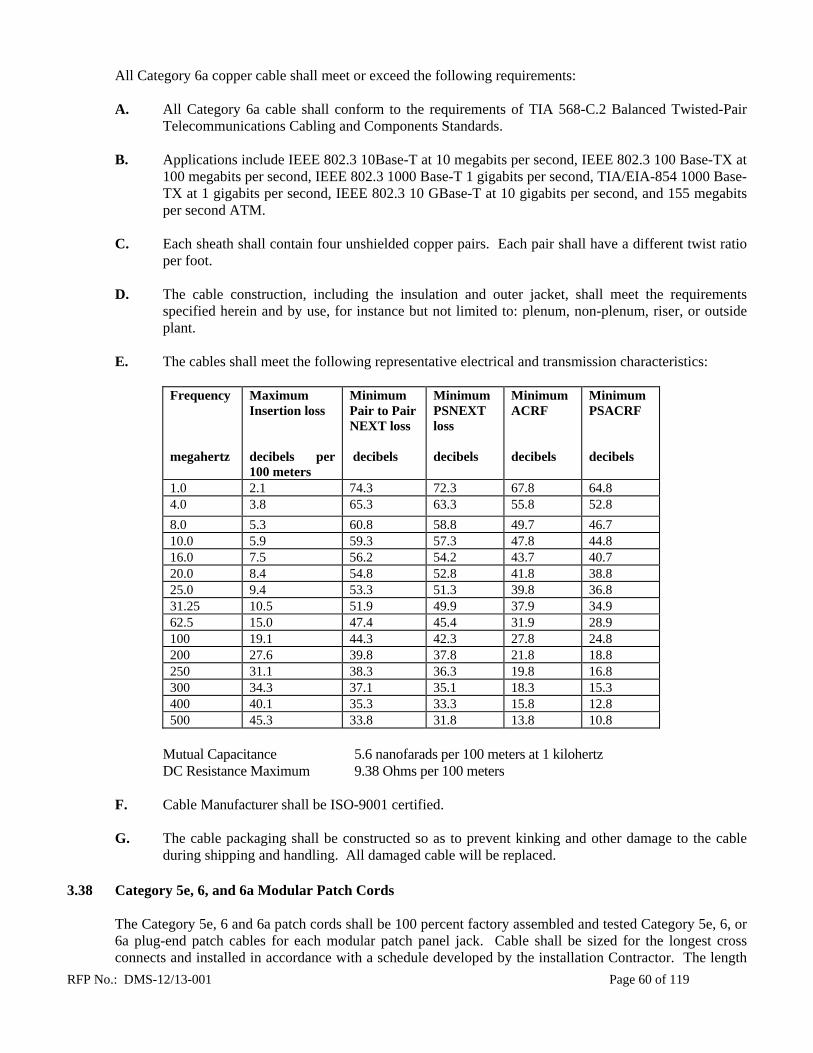
RFP No.: DMS-12/13-001 Page 60 of 119
All Category 6a copper cable shall meet or exceed the following requirements: A. All Category 6a cable shall conform to the requirements of TIA 568-C.2 Balanced Twisted-Pair
Telecommunications Cabling and Components Standards.
B. Applications include IEEE 802.3 10Base-T at 10 megabits per second, IEEE 802.3 100 Base-TX at 100 megabits per second, IEEE 802.3 1000 Base-T 1 gigabits per second, TIA/EIA-854 1000 Base-TX at 1 gigabits per second, IEEE 802.3 10 GBase-T at 10 gigabits per second, and 155 megabits per second ATM.
C. Each sheath shall contain four unshielded copper pairs. Each pair shall have a different twist ratio
per foot.
D. The cable construction, including the insulation and outer jacket, shall meet the requirements specified herein and by use, for instance but not limited to: plenum, non-plenum, riser, or outside plant.
E. The cables shall meet the following representative electrical and transmission characteristics:
Frequency megahertz
Maximum Insertion loss decibels per 100 meters
Minimum Pair to Pair NEXT loss decibels
Minimum PSNEXT loss decibels
Minimum ACRF decibels
Minimum PSACRF decibels
1.0 2.1 74.3 72.3 67.8 64.8 4.0 3.8 65.3 63.3 55.8 52.8
8.0 5.3 60.8 58.8 49.7 46.7 10.0 5.9 59.3 57.3 47.8 44.8 16.0 7.5 56.2 54.2 43.7 40.7 20.0 8.4 54.8 52.8 41.8 38.8 25.0 9.4 53.3 51.3 39.8 36.8 31.25 10.5 51.9 49.9 37.9 34.9 62.5 15.0 47.4 45.4 31.9 28.9 100 19.1 44.3 42.3 27.8 24.8 200 27.6 39.8 37.8 21.8 18.8 250 31.1 38.3 36.3 19.8 16.8 300 34.3 37.1 35.1 18.3 15.3 400 40.1 35.3 33.3 15.8 12.8 500 45.3 33.8 31.8 13.8 10.8
Mutual Capacitance 5.6 nanofarads per 100 meters at 1 kilohertz DC Resistance Maximum 9.38 Ohms per 100 meters
F. Cable Manufacturer shall be ISO-9001 certified.
G. The cable packaging shall be constructed so as to prevent kinking and other damage to the cable during shipping and handling. All damaged cable will be replaced.
3.38 Category 5e, 6, and 6a Modular Patch Cords
The Category 5e, 6 and 6a patch cords shall be 100 percent factory assembled and tested Category 5e, 6, or 6a plug-end patch cables for each modular patch panel jack. Cable shall be sized for the longest cross connects and installed in accordance with a schedule developed by the installation Contractor. The length

RFP No.: DMS-12/13-001 Page 61 of 119
of the patch cable shall not exceed 25 feet. Provide color coded boot assemblies to match the Project Contact’s requirements. A. All Category 5e, 6, or 6a patch cords shall be round, and consist of 24 AWG copper, stranded
conductors insulated with high density polyethylene, tightly twisted into individual pairs and jacketed with flame retardant PVC and shall meet or exceed the specifications listed below:
Plug insertion life - minimum 750 plug insertions Plug Retention Force - 110 newton minimum between modular plug and jack
B. All Category 5e, 6, and 6a patch cord cables shall conform to the requirements of TIA 568-C.2
Balanced Twisted-Pair Telecommunications Cabling and Components Standards and shall meet the electrical and transmission characteristics therein. All Category 5e, 6, and 6a patch cord cables shall meet the requirements of Category 5e, 6, and 6a cables in Section 3.34, 3.36, and 3.37 respectively.
C. The patch cords shall have built-in exclusion features to prevent accidental polarity reversals and
split pairs.
D. Cable Manufacturer shall be ISO-9001 certified.
E. The cable packaging shall be constructed so as to prevent kinking and other damage to the cable during shipping and handling. All damaged cable will be replaced.
3.39 Category 5e, 6, and 6a Patch Panels with 110 Termination
All Category 5e, 6, and 6a patch panels shall have eight wires, 8-position modular jacks (RJ-45) with 110 terminations on the rear for connection of station cables. The Category 5e, 6, and 6a cables to the outlets will be directly connected to 110 insulation displacement hardware associated with each jack on the patch panel. These panels will be designed to operate at a minimum of 100, 250, and 500 MHz for Category 5e, 6, and 6a respectively. Quantities sufficient for all positions of every outlet are required.
A. The patch panel shall be a Category 5e, 6, and 6a modular jack panel with the following
characteristics: 1. The patch panel will utilize a 110 insulation displacement connector field on the back of the
panel to terminate the horizontal cables. The 110 field is to remain continuous to the 8-pin modular jack field in the front of the panel.
2. The cross-connect patch panel shall meet TIA 568-C.2 Balanced Twisted-PairTelecommunications Cabling and Components Standards.
B. The Category 5e panels shall be approved to work in all applications up to 100 megahertz.

RFP No.: DMS-12/13-001 Page 62 of 119
C. The Category 5e panels shall meet or exceed the following representative electrical and transmission characteristics:
Frequency
megahertz
Maximum Insertion loss
Decibels
Minimum NEXT loss
decibels
Minimum FEXT loss
decibels
1.0 0.10 65.0 65.0 4.0 0.10 65.0 63.1 8.0 0.11 64.9 57.0
10.0 0.13 63.0 55.1
16.0 0.16 58.9 51.0 20.0 0.18 57.0 49.1 25.0 0.20 55.0 47.1
31.25 0.22 53.1 45.2
62.5 0.32 47.1 39.2 100. 0.40 43.0 35.1
D. The Category 6 panels shall be approved to work in all applications up to 250 megahertz.
E. The Category 6 panels shall meet or exceed the following representative electrical and transmission
characteristics:
Frequency
megahertz
Maximum Insertion loss
Decibels
Minimum NEXT loss
decibels
Minimum FEXT loss
decibels
1.0 0.10 75.0 75.0 4.0 0.10 75.0 71.1 8.0 0.10 75.0 65.0
10.0 0.10 74.0 63.1 16.0 0.10 69.9 59.0 20.0 0.10 68.0 57.1 25.0 0.10 66.0 55.1
31.25 0.11 64.1 53.2 62.5 0.16 58.1 47.2 100 0.20 54.0 43.1 200 0.28 48.0 37.1 250 0.32 46.0 35.1
F. The Category 6a panels shall be approved to work in all applications up to 500 megahertz.
This space intentionally left blank.

RFP No.: DMS-12/13-001 Page 63 of 119
G. The Category 6a panels shall meet or exceed the following representative electrical and transmission characteristics:
Frequency
megahertz
Maximum Insertion loss
Decibels
Minimum NEXT loss
decibels
Minimum FEXT loss
decibels
1.0 0.10 75.0 75.0 4.0 0.10 75.0 71.1 8.0 0.10 75.0 65.0
10.0 0.10 74.0 63.1 16.0 0.10 69.9 59.0 20.0 0.10 68.0 57.1 25.0 0.10 66.0 55.1
31.25 0.11 64.1 53.2 62.5 0.16 58.1 47.2 100 0.20 54.0 43.1 200 0.28 48.0 37.1 250 0.32 46.0 35.1 300 0.35 42.9 33.6 400 0.40 37.9 31.1 500 0.45 34.0 29.1
3.40 Category 5e, 6, and 6a Blank Face Patch Panels with Modular Jack Termination
The blank patch panels shall have blank faces with cutouts that accept Category 5e, 6, and 6a snap-in modular jacks. These panels, when populated, will be designed to operate at a minimum of 100, 250, and 500 megahertz for Category 5e, 6, and 6a respectively. Modular jack quantities sufficient for all positions of every outlet are required.
A. The patch panels shall be Category 5e, 6, and 6a modular jack panels and shall meet TIA 568-C.2
Balanced Twisted-Pair Telecommunications Cabling and Components Standards.
B. The Category 5e panels shall be approved to work in all applications up to 100 megahertz and the Category 5e modular jacks shall meet or exceed the electrical and transmission characteristics contained herein.
C. The Category 6 panels shall be approved to work in all applications up to 250 megahertz and Category 6 modular jacks shall meet or exceed the electrical and transmission characteristics contained herein.
D. The Category 6a panels shall be approved to work in all applications up to 500 megahertz and Category 6a modular jacks shall meet or exceed the electrical and transmission characteristics contained herein.
This space intentionally left blank.
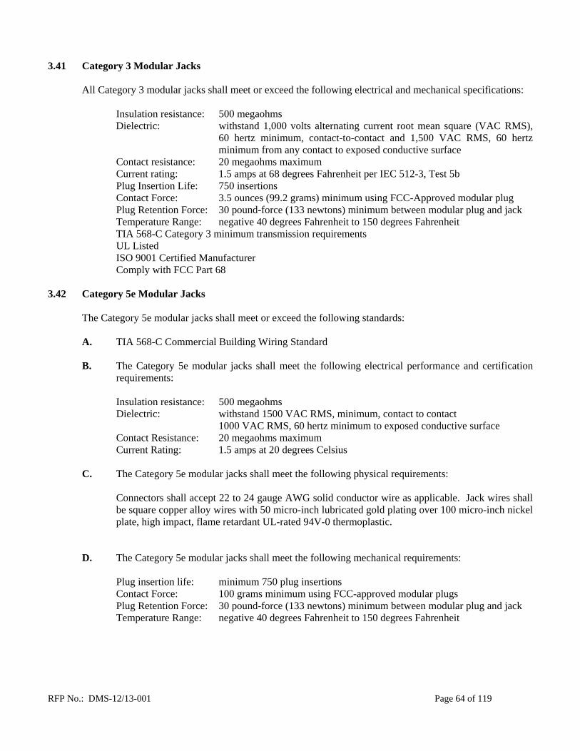
RFP No.: DMS-12/13-001 Page 64 of 119
3.41 Category 3 Modular Jacks
All Category 3 modular jacks shall meet or exceed the following electrical and mechanical specifications:
Insulation resistance: 500 megaohms
Dielectric: withstand 1,000 volts alternating current root mean square (VAC RMS), 60 hertz minimum, contact-to-contact and 1,500 VAC RMS, 60 hertz minimum from any contact to exposed conductive surface
Contact resistance: 20 megaohms maximum Current rating: 1.5 amps at 68 degrees Fahrenheit per IEC 512-3, Test 5b Plug Insertion Life: 750 insertions
Contact Force: 3.5 ounces (99.2 grams) minimum using FCC-Approved modular plug Plug Retention Force: 30 pound-force (133 newtons) minimum between modular plug and jack Temperature Range: negative 40 degrees Fahrenheit to 150 degrees Fahrenheit
TIA 568-C Category 3 minimum transmission requirements UL Listed ISO 9001 Certified Manufacturer Comply with FCC Part 68
3.42 Category 5e Modular Jacks
The Category 5e modular jacks shall meet or exceed the following standards:
A. TIA 568-C Commercial Building Wiring Standard
B. The Category 5e modular jacks shall meet the following electrical performance and certification
requirements:
Insulation resistance: 500 megaohms Dielectric: withstand 1500 VAC RMS, minimum, contact to contact 1000 VAC RMS, 60 hertz minimum to exposed conductive surface Contact Resistance: 20 megaohms maximum Current Rating: 1.5 amps at 20 degrees Celsius
C. The Category 5e modular jacks shall meet the following physical requirements:
Connectors shall accept 22 to 24 gauge AWG solid conductor wire as applicable. Jack wires shall be square copper alloy wires with 50 micro-inch lubricated gold plating over 100 micro-inch nickel plate, high impact, flame retardant UL-rated 94V-0 thermoplastic.
D. The Category 5e modular jacks shall meet the following mechanical requirements:
Plug insertion life: minimum 750 plug insertions Contact Force: 100 grams minimum using FCC-approved modular plugs Plug Retention Force: 30 pound-force (133 newtons) minimum between modular plug and jack Temperature Range: negative 40 degrees Fahrenheit to 150 degrees Fahrenheit

RFP No.: DMS-12/13-001 Page 65 of 119
E. The outlet shall be approved to work in all applications up to 100 megahertz.
Frequency
megahertz
Maximum Insertion loss
Decibels
Minimum NEXT loss decibels
Minimum FEXT loss
decibels
1.0 0.10 65.0 65.0 4.0 0.10 65.0 63.1 8.0 0.11 64.9 57.0
10.0 0.13 63.0 55.1
16.0 0.16 58.9 51.0 20.0 0.18 57.0 49.1 25.0 0.20 55.0 47.1
31.25 0.22 53.1 45.2
62.5 0.32 47.1 39.2 100 0.40 43.0 35.1
3.43 Category 6 Modular Jacks
The Category 6 modular jacks shall meet or exceed the following standards:
A. TIA 568-C Commercial Building Wiring Standard
B. The Category 6 modular jacks shall meet the following physical requirements:
Connectors accepting 22 to 24 gauge AWG solid conductor wire as applicable. Jack wires shall be square copper alloy wires with 50 micro-inch lubricated gold plating over 100 micro-inch nickel plate, high impact, and flame retardant UL-rated 94V-0 thermoplastic.
C. The Category 6 modular jacks shall meet the following mechanical requirements:
Plug insertion life: minimum 750 plug insertions Contact Force: 100 grams minimum using FCC-approved modular plugs Plug Retention Force: 133 newtons minimum between modular plug and jack Temperature Range: negative 40 degrees Fahrenheit to 150 degrees Fahrenheit
The outlet shall be approved to work in all applications up to 250 MHz.
Frequency
megahertz
Maximum Insertion loss
Decibels
Minimum NEXT loss
decibels
Minimum FEXT loss
decibels 1.0 0.10 75.0 75.0 4.0 0.10 75.0 71.1 8.0 0.10 75.0 65.0
10.0 0.10 74.0 63.1 16.0 0.10 69.9 59.0 20.0 0.10 68.0 57.1 25.0 0.10 66.0 55.1
31.25 0.11 64.1 53.2 62.5 0.16 58.1 47.2 100 0.20 54.0 43.1 200 0.28 48.0 37.1 250 0.32 46.0 35.1
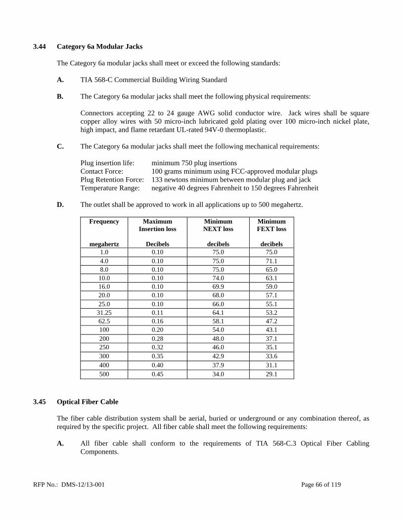
RFP No.: DMS-12/13-001 Page 66 of 119
3.44 Category 6a Modular Jacks
The Category 6a modular jacks shall meet or exceed the following standards:
A. TIA 568-C Commercial Building Wiring Standard
B. The Category 6a modular jacks shall meet the following physical requirements:
Connectors accepting 22 to 24 gauge AWG solid conductor wire. Jack wires shall be square copper alloy wires with 50 micro-inch lubricated gold plating over 100 micro-inch nickel plate, high impact, and flame retardant UL-rated 94V-0 thermoplastic.
C. The Category 6a modular jacks shall meet the following mechanical requirements:
Plug insertion life: minimum 750 plug insertions Contact Force: 100 grams minimum using FCC-approved modular plugs Plug Retention Force: 133 newtons minimum between modular plug and jack Temperature Range: negative 40 degrees Fahrenheit to 150 degrees Fahrenheit
D. The outlet shall be approved to work in all applications up to 500 megahertz.
Frequency
megahertz
Maximum Insertion loss
Decibels
Minimum NEXT loss
decibels
Minimum FEXT loss
decibels
1.0 0.10 75.0 75.0 4.0 0.10 75.0 71.1 8.0 0.10 75.0 65.0
10.0 0.10 74.0 63.1 16.0 0.10 69.9 59.0 20.0 0.10 68.0 57.1 25.0 0.10 66.0 55.1
31.25 0.11 64.1 53.2 62.5 0.16 58.1 47.2 100 0.20 54.0 43.1 200 0.28 48.0 37.1 250 0.32 46.0 35.1 300 0.35 42.9 33.6 400 0.40 37.9 31.1 500 0.45 34.0 29.1
3.45 Optical Fiber Cable
The fiber cable distribution system shall be aerial, buried or underground or any combination thereof, as required by the specific project. All fiber cable shall meet the following requirements:
A. All fiber cable shall conform to the requirements of TIA 568-C.3 Optical Fiber Cabling
Components.

RFP No.: DMS-12/13-001 Page 67 of 119
B. The cable construction, including the insulation and outer jacket, shall meet the requirements specified herein and by use, for instance but not limited to: plenum, non-plenum, riser, armored or outside plant.
C. Cable Manufacturer shall be ISO-9001 certified.
D. The cable packaging shall be constructed so as to prevent kinking and other damage to the cable during shipping and handling. All damaged cable will be replaced.
E. All optical fibers shall be sufficiently free of surface imperfections and inclusions to meet the
optical, mechanical, and environmental requirements of the specification herein. All fibers in the cable must be usable.
F. All fibers in the cable shall meet maximum attenuation and minimum bandwidth. Cables that state
attenuation and bandwidth as average or nominal values are unacceptable. All optical fibers shall be 100 percent attenuation tested. The attenuation of each fiber shall be provided with each cable reel. The attenuation shall be measured at 850 nanometers and 1300 nanometers for multimode fibers and 1310 nanometers and 1550 nanometers for single-mode fibers.
3.46 Plenum Fiber Cable
Plenum rated fiber cable shall be certified to conform to NFPA 262 and be Optical Fiber Nonconductive Plenum (OFNP) rated.
3.47 Riser Fiber Cable
Riser rated fiber cable shall be certified to conform to UL 1666 and be Optical Fiber Nonconductive Riser (OFNR) rated.
3.48 Outside Plant Fiber Cable
Outside plant fiber cable shall have a medium-density polyethylene jacket to provide durability and superior protection against ultraviolet radiation, fungus, and abrasions. The outside plant fiber cable shall have water blocking technology to prevent the migration of water throughout the cable. Outside Plant fiber cable shall have minimum pull strength of 260 newtons (600 pound-force). Outside Plant fiber cable shall support a bend radius of 10 times the cable outside diameter when not subject to tensile load, and 20 times the cable outside diameter when subject to tensile loading up to the cable’s rated limit.
3.49 Indoor/Outdoor Fiber Cable
The indoor/outdoor fiber cable shall be suitable for both riser and campus distribution applications. The fiber cable shall comply with the water-blocking requirement of TIA/EIA 455-82. Indoor/outdoor fiber cable shall have minimum pull strength of 260 newtons (600 pound-force). Indoor/outdoor fiber cable shall support a bend radius of 10 times the cable outside diameter when not subject to tensile load, and 20 times the cable outside diameter when subject to tensile loading up to the cable’s rated limit.
3.50 Tight Buffer Fiber Cable Construction
The tight buffer fiber cable shall be engineered to provide a superior operating environment for optimum fiber performance. Cable shall be a dry type swell-able cable waterblocking or a gel-filled or flooded technology. Tight buffer fiber cable shall meet the following specifications:

RFP No.: DMS-12/13-001 Page 68 of 119
A. Buffer The coated fiber shall have a low friction slip layer placed between the acrylate coating of the optical fiber and the thermoplastic buffer.
The fiber coating and buffer shall each be removable with commercially available stripping tools in a single pass for connector termination or splicing.
Both buffer tubes and fibers shall be individually color-coded for easy identification. Every cable shall be clearly marked for ease of identification.
B. Strength Yarns
The fibers shall be stranded around a dielectric strength element consisting of water blocking aramid strength yarns. The strength yarns shall be water swell-able to prevent the migration of water throughout the cable. The water blocking element shall be non-nutritive to fungus, electrically non-conductive, and homogenous. The purpose of the strength element is to provide tensile strength. The aramid yarns shall be helically stranded evenly around the buffered fibers.
Binders shall be applied with sufficient tension to secure the buffer tubes to the central member without crushing the buffer tubes. The binders shall be non-hygroscopic, non-wicking and dielectric with low shrinkage. Non-toxic and non-irritant talc shall be applied to the yarns to allow them to be easily separated from the fibers and the outer jacket.
C. Jacket
Cables shall be sheathed with flame-retardant polyvinyl chloride (PVC). The PVC shall contain carbon black to provide ultraviolet light protection and shall not promote the growth of fungus.
The cable shall contain at least one ripcord under the sheath for easy sheath removal. The jacket shall be continuous, free from pinholes, splits, blisters, or other imperfections. The jacket shall have a consistent, uniform thickness. Jackets extruded under high pressure are not acceptable. The jacket or sheath shall be marked with the Manufacturer’s name, the year of manufacture, the sequential meter or foot markings, fiber count, fiber type, flame rating and listing marking. The markings shall be repeated at least every one meter. The actual length of the cable shall be within plus or minus one percent of the length marking. The marking shall be in a contrasting color to the cable jacket. The height of the marking shall be approximately 2.5 millimeters.
D. Armor Armored tight buffered fiber cables shall include an interlocking aluminum armor applied helically around the outside of the cable jacket. The interlocking armor may be left un-jacketed or may have a PVC outer jacket. The armor for these cables shall be comparable to liquid tight flexible metal conduit if jacketed or flexible metal conduit if not jacketed.
E. Temperature
The installation temperature range for the tight buffered fiber cable shall be 0 degrees Celsius to 60 degrees Celsius for plenum cables and negative 10 degrees Celsius to 60 degrees Celsius for riser cable. The operating temperature range for the cable shall be negative 40 degrees Celsius to 70 degrees Celsius.

RFP No.: DMS-12/13-001 Page 69 of 119
3.51 Loose Tube Fiber Cable Construction The loose tube fiber cable shall be engineered to provide a superior operating environment for optimum fiber performance. Fibers shall be placed in buffer tubes and suspended in a filling compound that mechanically decouples the fiber from the cable structure. Fiber cable shall be a dry type swell-able cable waterblocking or a gel-filled or flooded technology. Loose tube fiber cable shall meet the following specifications:
A. Buffer Tubes
Optical fiber shall be placed inside a 2.5-millimeter outer diameter loose buffer tube. Each buffer tube shall contain up to 12 fibers. The fibers shall not adhere to the inside of the buffer tube. The cable shall utilize a highly reliable loose buffer tube design that shall contain multiple fibers within a buffer tube several times larger in diameter than the fibers. The extra space shall effectively isolate the fibers from the effects of tension and temperature felt by the cable, ensuring stable optical performance over a wide range of conditions. Buffer tubes shall be of a dual-layer construction with the inner layer made of polycarbonate and the outer layer made of polyester. Fillers shall be included in the cable core to lend symmetry to the cable cross-section where needed. Buffer tubes shall be stranded around a central member using the reverse oscillating, or “SZ,” stranding process to provide maximum cable flexibility while minimizing fiber strain. Each buffer tube shall contain a water blocking element for water-blocking protection. The water swell-able element shall be non-nutritive to fungus, electrically non-conductive, and homogenous. The buffer tubes shall be resistant to kinking. A one meter length of un-aged cable shall withstand a one meter static head or equivalent continuous pressure of water for one hour without leakage through the open cable end. Both buffer tubes and fibers shall be individually color coded for easy identification. Every cable shall be clearly marked for ease of identification.
B. Cable Core
The required number of buffer tubes containing 1 to 12 optical fibers in each tube, shall be stranded around a central member to form the cable core. The central member shall consist of a dielectric, glass reinforced plastic (GRP) rod. The purpose of the central member is to provide tensile strength and prevent buckling of the cable. The tensile strength shall be provided by the central member, and additional dielectric yarns as required. The dielectric yarns shall be helically stranded evenly around the cable core. Filler rods may be included as necessary to maintain the circularity of the cable core. Binders shall be applied with sufficient tension to secure the buffer tubes to the central member without crushing the buffer tubes. The binders shall be non-hygroscopic, non-wicking and dielectric with low shrinkage.
C. Jacket Cables shall be sheathed with flame-retardant PVC. The PVC shall contain carbon black to provide ultraviolet light protection and shall not promote the growth of fungus. The cable shall contain at least one ripcord under the sheath for easy sheath removal.

RFP No.: DMS-12/13-001 Page 70 of 119
The jacket shall be continuous, free from pinholes, splits, blisters, or other imperfections. The jacket shall have a consistent, uniform thickness. Jackets extruded under high pressure are not acceptable. The jacket shall be marked with the Manufacturer’s name, the year of manufacture, the sequential meter or foot markings, fiber count, fiber type, flame rating and listing marking. The markings shall be repeated at least every one meter. The actual length of the cable shall be within plus or minus one percent of the length marking. The marking shall be in a contrasting color to the cable jacket. The height of the marking shall be approximately 2.5 millimeters.
D. Armor Armored loose tube fiber cables shall include an interlocking aluminum armor applied helically around the outside of the cable jacket. The interlocking armor may be left un-jacketed or may have a PVC outer jacket. The armor for these cables shall be comparable to liquid tight flexible metal conduit if jacketed or flexible metal conduit if not jacketed.
E. Pulling Tension
The maximum pulling tension shall be 2700 newtons (600 pound-force) during installation (short term) and 810 newtons (180 pound-force) long term installed.
F. Temperature
The installation temperature range for the loose tube fiber cable shall be negative 10 degrees Celsius to 60 degrees Celsius. The operating temperature range for the cable shall be negative 40 degrees Celsius to 70 degrees Celsius.
3.52 Multimode 62.5/125 micron Tight Buffer Fiber (OM1) The multimode fiber utilized in the cable specified herein shall meet EIA/TIA-492AAAA-A and IEC 60793-2-10. The cable construction, including the insulation and outer jacket, shall meet the requirements specified herein and by use, for instance but not limited to, plenum, riser, armored, indoor/outdoor or outside plant. The 62.5/125 micron multimode optical fiber shall meet the following optical characteristics:
850 nanometers: maximum attenuation 3.4 decibels per kilometer minimum OFL bandwidth 200 megahertz-kilometer minimum Gigabit distance 300 meters
1300 nanometers: maximum attenuation 1.0 decibels per kilometer minimum OFL bandwidth 500 megahertz-kilometer minimum Gigabit distance 550 meters
The multimode fiber utilized in the cable specified herein shall conform to the following specifications: Buffered Fiber: 62.5/125 micron Core Diameter: 62.5 plus or minus 2.5 micrometers Core-to-Cladding Offset: less than or equal to 1.5 micrometers Fiber Dimensions: 125 micron cladding plus or minus 2 micrometers 242 micron coating plus or minus 5 micrometers

RFP No.: DMS-12/13-001 Page 71 of 119
3.53 Multimode 62.5/125 micron Loose Tube Fiber (OM1) The multimode fiber utilized in the cable specified herein shall meet EIA/TIA-492AAAA-A and IEC 60793-2-10. The cable construction, including the insulation and outer jacket, shall meet the requirements specified herein and by use, for instance but not limited to, plenum, riser, armored, indoor/outdoor or outside plant. The 62.5/125 micron multimode optical fiber shall meet the following optical characteristics:
850 nanometers: maximum attenuation 3.4 decibels per kilometer minimum OFL bandwidth 200 megahertz-kilometer minimum Gigabit distance 300 meters
1300 nanometers: maximum attenuation 1.0 decibels per kilometer minimum OFL bandwidth 500 megahertz-kilometer minimum Gigabit distance 550 meters
The multimode fiber utilized in the cable specified herein shall conform to the following specifications: Buffered Fiber: 62.5/125 micron Core Diameter: 62.5 plus or minus 2.5 micrometers Core-to-Cladding Offset: less than or equal to 1.5 micrometers Fiber Dimensions: 125 micron cladding plus or minus 2 micrometers 242 micron coating plus or minus 5 micrometers 3.54 Multimode 50/125 micron Tight Buffer Fiber (OM2)
The multimode fiber utilized in the cable specified herein shall meet TIA/EIA-492AAAB and IEC 60793-2-10. The cable construction, including the insulation and outer jacket, shall meet the requirements specified herein and by use, for instance but not limited to, plenum, riser, armored, indoor/outdoor or outside plant. The 50/125 micron multimode optical fiber shall meet the following optical characteristics:
850 nanometers: maximum attenuation 2.8 decibels per kilometer minimum OFL bandwidth 700 megahertz-kilometer minimum Gigabit distance 750 meters
1300 nanometers: maximum attenuation 1.0 decibels per kilometer minimum OFL bandwidth 500 megahertz-kilometer minimum Gigabit distance 600 meters
The multimode fiber utilized in the cable specified herein shall conform to the following specifications: Buffered Fiber: 50/125 micron Core Diameter: 50 plus or minus 2 micrometers Core-to-Cladding Offset: less than or equal to 1.5 micrometers Fiber Dimensions: 125 micron cladding plus or minus 2 micrometers 242 micron coating plus or minus 5 micrometers 3.55 Multimode 50/125 micron Loose Tube Fiber (OM2)
The multimode fiber utilized in the cable specified herein shall meet EIA/TIA-492AAAB and IEC 2-10. The cable construction, including the insulation and outer jacket, shall meet the requirements specified herein and by use, for instance but not limited to, plenum, riser, armored, indoor/outdoor or outside plant. The 50/125 micron multimode optical fiber shall meet the following optical characteristics:

RFP No.: DMS-12/13-001 Page 72 of 119
850 nanometers: maximum attenuation 3.0 decibels per kilometer minimum OFL bandwidth 700 megahertz-kilometer minimum Gigabit distance 750 meters
1300 nanometers: maximum attenuation 1.0 decibels per kilometer minimum OFL bandwidth 500 megahertz-kilometer minimum Gigabit distance 600 meters
The multimode fiber utilized in the cable specified herein shall conform to the following specifications: Buffered Fiber: 50/125 micron Core Diameter: 50 plus or minus 2 micrometers Core-to-Cladding Offset: less than or equal to 1.5 micrometers Fiber Dimensions: 125 micron cladding plus or minus 2 micrometers 242 micron coating plus or minus 5 micrometers 3.56 Multimode 50/125 micron Tight Buffer Fiber (OM3)
The multimode fiber utilized in the cable specified herein shall meet TIA/EIA-492AAAC and IEC 60793-2-10. The cable construction, including the insulation and outer jacket, shall meet the requirements specified herein and by use, for instance but not limited to, plenum, riser, armored, indoor/outdoor or outside plant. The 50/125 micron multimode optical fiber shall meet the following optical characteristics:
850 nanometers: maximum attenuation 2.8 decibels per kilometer minimum OFL bandwidth 1500 megahertz-kilometer minimum Gigabit distance 1000 meters
1300 nanometers: maximum attenuation 1.0 decibels per kilometer minimum OFL bandwidth 500 megahertz-kilometer minimum Gigabit distance 600 meters
The multimode fiber utilized in the cable specified herein shall conform to the following specifications: Buffered Fiber: 50/125 micron Core Diameter: 50 plus or minus 2 micrometers Core-to-Cladding Offset: less than or equal to 1.5 micrometers Fiber Dimensions: 125 micron cladding plus or minus 2 micrometers 242 micron coating plus or minus 5 micrometers
This space intentionally left blank.

RFP No.: DMS-12/13-001 Page 73 of 119
3.57 Multimode 50/125 micron Loose Tube Fiber (OM3)
The multimode fiber utilized in the cable specified herein shall meet EIA/TIA-492AAAC and IEC 2-10. The cable construction, including the insulation and outer jacket, shall meet the requirements specified herein and by use, for instance but not limited to, plenum, riser, armored, indoor/outdoor or outside plant. The 50/125 micron multimode optical fiber shall meet the following optical characteristics:
850 nanometers: maximum attenuation 3.0 decibels per kilometer minimum OFL bandwidth 1500 megahertz-kilometer minimum Gigabit distance 1000 meters
1300 nanometers: maximum attenuation 1.0 decibels per kilometer minimum OFL bandwidth 500 megahertz-kilometer minimum Gigabit distance 600 meters
The multimode fiber utilized in the cable specified herein shall conform to the following specifications: Buffered Fiber: 50/125 micron Core Diameter: 50 plus or minus 2 micrometers Core-to-Cladding Offset: less than or equal to 1.5 micrometers Fiber Dimensions: 125 micron cladding plus or minus 2 micrometers 242 micron coating plus or minus 5 micrometers 3.58 Multimode 50/125 micron Tight Buffer Fiber (OM4)
The multimode fiber utilized in the cable specified herein shall meet TIA/EIA-492AAAD and IEC 60793-2-10. The cable construction, including the insulation and outer jacket, shall meet the requirements specified herein and by use, for instance but not limited to, plenum, riser, armored, indoor/outdoor or outside plant. The 50/125 micron multimode optical fiber shall meet the following optical characteristics:
850 nanometers: maximum attenuation 2.8 decibels per kilometer minimum OFL bandwidth 3500 megahertz-kilometer minimum Gigabit distance 1100 meters
1300 nanometers: maximum attenuation 1.0 decibels per kilometer minimum OFL bandwidth 500 megahertz-kilometer minimum Gigabit distance 600 meters
The multimode fiber utilized in the cable specified herein shall conform to the following specifications: Buffered Fiber: 50/125 micron Core Diameter: 50 plus or minus 2 micrometers Core-to-Cladding Offset: less than or equal to 1.5 micrometers Fiber Dimensions: 125 micron cladding plus or minus 2 micrometers 242 micron coating plus or minus 5 micrometers 3.59 Multimode 50/125 micron Loose Tube Fiber (OM4)
The multimode fiber utilized in the cable specified herein shall meet TIA/EIA-492AAAD and IEC 60793-2-10. The cable construction, including the insulation and outer jacket, shall meet the requirements specified herein and by use, for instance but not limited to, plenum, riser, armored, indoor/outdoor or outside plant. The 50/125 micron multimode optical fiber shall meet the following optical characteristics:

RFP No.: DMS-12/13-001 Page 74 of 119
850 nanometers: maximum attenuation 3.0 decibels per kilometer minimum OFL bandwidth 3500 megahertz-kilometer minimum Gigabit distance 1100 meters
1300 nanometers: maximum attenuation 1.0 decibels per kilometer minimum OFL bandwidth 500 megahertz-kilometer minimum Gigabit distance 600 meters
The multimode fiber utilized in the cable specified herein shall conform to the following specifications: Buffered Fiber: 50/125 micron Core Diameter: 50 plus or minus 2 micrometers Core-to-Cladding Offset: less than or equal to 1.5 micrometers Fiber Dimensions: 125 micron cladding plus or minus 2 micrometers 242 micron coating plus or minus 5 micrometers 3.60 Single-mode Tight Buffer Fiber
The single-mode fiber utilized in the cable specified herein shall meet TIA/EIA-492CAAB. The cable construction, including the insulation and outer jacket, shall meet the requirements specified herein and by use, for instance but not limited to, plenum, riser, armored, indoor/outdoor or outside plant. The single-mode optical fiber shall meet the following optical characteristics:
1310 nanometers: maximum attenuation 0.65 decibels per kilometer
minimum Gigabit distance 5000 meters
1550 nanometers: maximum attenuation 0.50 decibels per kilometer
The single-mode fiber utilized in the cable specified herein shall conform to the following specifications: Core-to-Cladding Concentricity: less than or equal to 0.5 micrometers Cladding Non-circularity: less than or equal to 0.7 percent Fiber Dimensions: 125 micron cladding plus or minus 0.7 micrometers 245 micron coating plus or minus 5 micrometers Zero Dispersion Wavelength: 1313 plus or minus 11 nanometers Cable Cutoff Wavelength: 1260 nanometers
This space intentionally left blank.

RFP No.: DMS-12/13-001 Page 75 of 119
3.61 Single-mode Loose Filled Fiber
The single-mode fiber utilized in the cable specified herein shall meet TIA/EIA-492CAAB and IEC 60793-2-50. The cable construction, including the insulation and outer jacket, shall meet the requirements specified herein and by use, for instance but not limited to, plenum, riser, armored, indoor/outdoor or outside plant. The single-mode optical fiber shall meet the following optical characteristics:
1310 nanometers: maximum attenuation 0.4 decibels per kilometer minimum Gigabit distance 5000 meters
1550 nanometers: maximum attenuation 0.30 decibels per kilometer
The single-mode fiber utilized in the cable specified herein shall conform to the following specifications: Core-to-Cladding Concentricity: less than or equal to 0.5 micrometers Cladding Non-circularity: less than or equal to 0.7 percent Fiber Dimensions: 125 micron cladding plus or minus 0.7 micrometers 245 micron coating plus or minus 5 micrometers Zero Dispersion Wavelength: 1313 plus or minus 11 nanometers Cable Cutoff Wavelength: 1260 nanometers 3.62 Fiber Patch Cables
Fiber connectors for the fiber patch cables shall match the fiber connector specifications specified herein. The patch cable fiber shall match the optical characteristics and specifications of the fiber cable specified herein.
3.63 ST Fiber Connector and Termination
The only approved method of fiber termination using an ST connector is one approved by the cable manufacturer for the specific cable supplied. The connector shall be installed on the fiber utilizing an approved tool kit. This kit contains all tools and instructions to mount the connector quickly and easily, utilizing the manufacturer’s installation procedures. The ST fiber connectors and terminations shall meet the following specifications:
A. Multimode The only approved method of termination is as specified in TIA-568 C.3 Optical Fiber Cabling
Components. The connector shall meet the following requirements: Durability: 500 re-matings Typical Insertion Loss: 0.2 decibels Maximum Insertion Loss: 0.5 decibels Maximum Temperature Cycling: 0.3 decibels

RFP No.: DMS-12/13-001 Page 76 of 119
B. Single-mode The only approved method of termination is as specified in TIA-568 C.3 Optical Fiber Cabling
Components. The connector shall meet the following requirements: Durability: 500 re-matings Typical Insertion Loss: 0.2 decibels Maximum Insertion Loss: 0.5 decibels Maximum Temperature Cycling: 0.3 decibels
3.64 SC Fiber Connector and Termination
The only approved method of fiber termination using an SC connector is one approved by the cable manufacturer for the specific cable supplied. The connector shall be installed on the fiber utilizing an approved tool kit. This kit contains all tools and instructions to mount the connector quickly and easily, utilizing the manufacturer’s installation procedures. The SC fiber connectors and terminations shall meet the following specifications:
A. Multimode The only approved method of termination is as specified in TIA-568 C.3 Optical Fiber Cabling
Components. The connector shall meet the following requirements:
Durability: 500 re-matings Typical Insertion Loss: 0.1 decibels Maximum Insertion Loss: 0.5 decibels Maximum Temperature Cycling: 0.3 decibels
B. Single-mode The only approved method of termination is as specified in TIA-568 C.3 Optical Fiber Cabling
Components. The connector shall meet the following requirements: Durability: 500 re-matings Typical Insertion Loss: 0.2 decibels Maximum Insertion Loss: 0.5 decibels Maximum Temperature Cycling: 0.3 decibels
3.65 LC Fiber Connector and Termination
The only approved method of fiber termination using an LC connector is one approved by the cable manufacturer for the specific cable supplied. The connector shall be installed on the fiber utilizing an approved tool kit. This kit contains all tools and instructions to mount the connector quickly and easily, utilizing the manufacturer’s installation procedures. The LC fiber connectors and terminations shall meet the following specifications:
A. Multimode The only approved method of termination is as specified in TIA-568 C.3 Optical Fiber Cabling
Components. The connector shall meet the following requirements:
Durability: 500 re-matings Typical Insertion Loss: 0.1 decibels Maximum Insertion Loss: 0.5 decibels Maximum Temperature Cycling: 0.3 decibels

RFP No.: DMS-12/13-001 Page 77 of 119
B. Single-mode The only approved method of termination is as specified in TIA-568 C.3 Optical Fiber Cabling
Components. The connector shall meet the following requirements:
Durability: 500 re-matings Typical Insertion Loss: 0.2 decibels Maximum Insertion Loss: 0.5 decibels Maximum Temperature Cycling: 0.3 decibels
3.66 Optical Fiber Cable Interconnect Cabinet
All fiber cables will be terminated at the telecommunication room sites in fiber interconnect cabinets. These cabinets will be wall or rack mounted, as designated on the drawings or as required by the Project Contact. Rack mounted interconnect cabinets shall be placed at the top of the rack and located to minimize cable distance to electronic equipment. Provide quantities and configurations as shown on the drawings. The fiber interconnect cabinet shall be a certified component and will directly terminate the fiber building cable. The fiber interconnect cabinet shall meet or exceed all the following requirements:
A. The fiber unit kit shall contain all parts required for termination of the cable with the specified
connectors and couplings.
B. The unit shall accommodate the connectors specified.
C. Provide plastic split rings fiber bend limiters for routing and expressing cables to manage slack fiber within the unit and rings for routing cable through the unit. It will also contain cable tie brackets for entry and exit of the fiber cable.
D. Include provision for labeling of the terminations and installation instructions.
E. Labeling for fiber cabling and cabinet shall be by distribution frame number, plus the color suffix
designating which fiber is terminated.
F. Include access for cable entry and provide inserts to enclose the cabinet around the cable entry area.
G. The cabinet shall be UL listed.
H. Include grounding lugs in the rear of the unit.
I. The interconnect cabinet shall provide cross-connect, inter-connect, splicing capabilities and
contain the proper troughs for supporting and routing the fiber cables.
J. The interconnect cabinet shall consist of a modular enclosure with retainer rings in the slack storage section to limit the bending radius of fibers.
K. The steel enclosure, designed for industrial application, shall come with a removable outer door
and inner door for securing the network section. The interconnect cabinet shall have bottom knockouts for cable entry. The interconnect cabinet shall have a “window” section to insert connector panels for mounting of terminated fibers.
L. All loose tube filled cables shall be provided with fan-out kits at each termination point.
M. The Contractor shall assure that the connectors for each cabling segment are installed in the correct

RFP No.: DMS-12/13-001 Page 78 of 119
orientation to ensure proper polarity of an optical fiber system from the main cross-connect to the telecommunications outlet or connector.
3.67 Optical Fiber Cable Splices & Closures
All fiber cable splicing shall be performed by the Contractor using the fusion splicing method unless the Project Contact specifically requires the mechanical method. Fiber cable splicing shall meet or exceed the following specifications:
A. Fusion
The fiber splicer shall be fully automatic, calibrated, and operate under the various jobsite environmental conditions (e.g., temperature, humidity, altitude, etc.) for all types of fiber cable being deployed.
1. The mean splice loss for identical dispersion-unshifted single mode fibers shall be equal to
0.05 decibels at 1310 nanometers and 1550 nanometers wavelengths in accordance with CCITT G.652.
2. The microprocessor controlled automatic positioning system shall control the fiber alignment, cleaning, gap-setting correlation of fiber positioning and fusing.
3. The fusion splicer shall measure and document the splice losses of each splice. These measurements shall be saved and submitted to the DMS Product Manager, during final documentation reporting requirements.
4. Heat shrink protection shall be provided for each splice.
B. Mechanical The fiber splice module shall meet the following specifications:
1. Accept 250 and 900 micron fibers 2. Re-enterable, rearrangeable and reusable 3. Require no polishing 4. Require no adhesives 5. No loose parts 6. Mean splice loss 0.15 decibels 7. Blind splice loss less than 0.5 decibels 8. One part index matching gel 9. Stable from negative 40 degrees Celsius to 75 degrees Celsius
C. Splice Closures
The fiber splice canister closure shall seal, bond, anchor, and protect fiber optic cable splices. The splice closure shall be re-enterable with a maximum of six cable entries in a butt-end configuration. The cap shall be capable of accepting additional cables without disturbing existing splices. The splice closure shall be designed for application required aerial, underground, and direct buried. It shall use corrosion free construction designed for splicing fibers. The unit shall include slack storage and the splice trays required for the specific project installation.
3.68 Plenum Coaxial Cable
Plenum rated coaxial cable shall be certified to conform to NFPA 262 and shall be marked as CMP. The plenum coaxial cable shall be composed of 22 to 24 gauge bare solid copper conductors insulated with FEP. The conductor shall be jacketed with low smoke, flame-retardant PVC.

RFP No.: DMS-12/13-001 Page 79 of 119
3.69 Flooded Coaxial Cable All flooded coaxial cable shall be injected with a water resistant flooding compound and jacketed with UV resistant polyethylene.
3.70 RG-6/U Coaxial Cable
All RG-6/U coaxial cables shall be round and consist of 18 AWG solid bare copper conductors individually insulated and sheathed with an outer jacket. A. The RG-6/U coaxial cable shall conform to the requirements of TIA 568-C.4 Broadband Coaxial
Cabling and Components Standard.
B. The RG-6/U coaxial cable construction, including the insulation and outer jacket, shall meet the requirements specified herein and by use, for instance but not limited to: plenum, non-plenum, or flooded.
C. The RG-6/U coaxial cable shall meet the following requirements:
Insulation Dielectric: Foam fluorinated ethylene propylene (FEP) Shield Type and Minimum Coverage: braid shield at 95 percent Nominal Impedance: 75 Ohms Maximum Attenuation at 750 megahertz: 5.65 decibels per 100 feet
D. Cable Manufacturer shall be ISO-9001 certified.
E. The cable packaging shall be constructed so as to prevent kinking and other damage to the cable
during shipping and handling. All damaged cable will be replaced. 3.71 RG-6/UQ Coaxial Cable
All RG-6/UQ coaxial cables shall be round and consist of 18 AWG solid bare copper conductors individually insulated, with four layers of shielding, and sheathed with an outer jacket.
A. The RG-6/UQ coaxial cable shall conform to the requirements of TIA 568-C.4 Broadband Coaxial
Cabling and Components Standard.
B. The RG-6/UQ coaxial cable construction, including the insulation and outer jacket, shall meet the requirements specified herein and by use, for instance but not limited to: plenum, non-plenum, or flooded.
C. The RG-6/UQ coaxial cable shall meet the following requirements:
Insulation Dielectric: Foam fluorinated ethylene propylene (FEP) Shield Type and Minimum Coverage: braid shield at 95 percent Nominal Impedance: 75 Ohms Maximum Attenuation at 750 megahertz: 5.65 decibels per 100 feet
D. Cable Manufacturer shall be ISO-9001 certified.
E. The cable packaging shall be constructed so as to prevent kinking and other damage to the cable
during shipping and handling. All damaged cable will be replaced.

RFP No.: DMS-12/13-001 Page 80 of 119
3.72 RG-11/U Coaxial Cable All RG-11/U coaxial cables shall be round and consist of 14 AWG solid bare copper conductor individually insulated and sheathed with an outer jacket.
A. The RG-11/U coaxial cable shall conform to the requirements of TIA 568-C.4 Broadband Coaxial
Cabling and Components Standard.
B. The RG-11/U coaxial cable construction, including the insulation and outer jacket, shall meet the requirements specified herein and by use, for instance but not limited to: plenum, non-plenum, or flooded.
C. The RG-11/U coaxial cable shall meet the following requirements:
Insulation Dielectric: Foam fluorinated ethylene propylene (FEP) Shield Type and Minimum Coverage: braid shield at 95 percent Nominal Impedance: 75 Ohms Maximum Attenuation at 750 megahertz: 3.65 decibels per 100 feet
D. Cable Manufacturer shall be ISO-9001 certified.
E. The cable packaging shall be constructed so as to prevent kinking and other damage to the cable
during shipping and handling. All damaged cable will be replaced. 3.73 RG-59/U Coaxial Cable
All RG-59/U coaxial cables shall be round and consist of 23 AWG solid bare copper conductor individually insulated and sheathed with an outer jacket.
A. The RG-59/U coaxial cable shall conform to the requirements of TIA 568-C.4 Broadband Coaxial
Cabling and Components Standard.
B. The RG-59/U coaxial cable construction, including the insulation and outer jacket, shall meet the requirements specified herein and by use, for instance but not limited to: plenum, non-plenum, or flooded.
C. The RG-59 coaxial cable shall meet the following requirements:
Insulation Dielectric: Foam fluorinated ethylene propylene (FEP) Shield Type and Minimum Coverage: braid shield braid shield at 95 percent Nominal Impedance: 75 Ohms Maximum Attenuation at 750 megahertz: 9.708 decibels per 100 feet
D. Cable Manufacturer shall be ISO-9001 certified.
E. The cable packaging shall be constructed so as to prevent kinking and other damage to the cable
during shipping and handling. All damaged cable will be replaced.

RFP No.: DMS-12/13-001 Page 81 of 119
3.74 Cable Connectors and Accessories All coaxial cable connectors and accessories shall consist of and meet or exceed the following specifications:
A. Connectors and Accessories
1. Male “F” Connector, Crimp-On, RG-59 Series Male “F” Connector, Crimp-On, RG-6 Series Male “F” Connector, Crimp-On, RG-11 Series Male BNC Connector, Crimp-On, three-piece, RG-59 Series Coaxial Adapter, “F” Inline Splice, Female to Female Coaxial Adapter, “F” Inline Splice, Female to Female with Nut and Washer Coaxial “F” Terminator, 75 Ohms Coaxial BNC Adapter, Female-to-Female Splice Coaxial BNC Adapter, BNC “T” Female Coaxial BNC Terminator, 75 Ohms
Wall Plate, with Female-to-Female “F” Connector
B. Passive Splitters, 5-750 Megahertz 1. Passive Two-Way Splitter, 5-750 megahertz
Maximum Splitter Loss per Output, 5-500 megahertz: 3.5 decibels Maximum Splitter Loss per Output, 500-600 megahertz: 4.0 decibels Maximum Splitter Loss per Output, 600-750 megahertz: 4.5 decibels Input Return Loss: 17 decibels, Minimum Isolation between Outputs: 27 decibels, Minimum RFI Shielding: 80 decibels, Minimum Connector Orientation: In-Line
2. Passive Three-Way Splitter, 5-750 megahertz
Maximum Splitter Loss per Output, 5-500 megahertz: 5.2 decibels Maximum Splitter Loss per Output, 500-600 megahertz: 5.5 decibels Maximum Splitter Loss per Output, 600-750 megahertz: 6.0 decibels Input Return Loss: 17 decibels, Minimum Isolation between Outputs: 27 decibels, Minimum RFI Shielding: 80 decibels, Minimum Connector Orientation: In-Line
3. Passive Four-Way Splitter, 5-750 megahertz
Maximum Splitter Loss per Output, 5-500 megahertz: 7.2 decibels Maximum Splitter Loss per Output, 500-600 megahertz: 8.0 decibels Maximum Splitter Loss per Output, 600-750 megahertz: 8.8 decibels Input Return Loss: 18 decibels, Minimum Isolation between Outputs: 27 decibels, Minimum RFI Shielding: 80 decibels, Minimum Connector Orientation: In-Line

RFP No.: DMS-12/13-001 Page 82 of 119
4. Passive Eight-Way Splitter, 5-750 megahertz Maximum Splitter Loss per Output, 5-450 megahertz: 12.0 decibels Maximum Splitter Loss per Output, 450-600 megahertz: 13.5 decibels Maximum Splitter Loss per Output, 600-750 megahertz: 14.0 decibels Input Return Loss: 14 decibels, Minimum Isolation between Outputs: 27 decibels, Minimum RFI Shielding: 80 decibels, Minimum Connector Orientation: In-Line
C. Indoor Directional Tap, Four Output, 5-750 MHz Tap Value: 8 decibels, All Ports Terminated Tap Value: 11 decibels, Minimum Isolation, Output to Tap, 21 decibels Tap Value: 14 decibels, Minimum Isolation, Output to Tap, 21 decibels Tap Value: 17 decibels, Minimum Isolation, Output to Tap, 23 decibels Tap Value: 20 decibels, Minimum Isolation, Output to Tap, 27 decibels Tap Value: 23 decibels, Minimum Isolation, Output to Tap, 29 decibels Tap Value: 26 decibels, Minimum Isolation, Output to Tap, 31 decibels Tap Value: 29 decibels, Minimum Isolation, Output to Tap, 35 decibels Tap Value: 32 decibels, Minimum Isolation, Output to Tap, 38 decibels Tap Value: 35 decibels, Minimum Isolation, Output to Tap, 40 decibels
D. Female-to-Male Fixed Attenuator, 5-750 MHz
Nominal Impedance, All Ports: 75 Ohms Return Loss: 18 decibels, Minimum Available Through-Loss Models: 3, 6, 10, and 20 decibels
3.75 Racks and Cabinets
The main distribution frame (MDF) shall be located in the communication equipment room, as designated on the drawings or as required by the Project Contact. The intermediate distribution frame (IDF) shall be located in the telecommunication rooms, as required by the specific Project. The MDF and IDF shall house racks, voice termination fields, and required cable routing hardware. Racks shall be placed by the Contractor in a manner that will allow a minimum of 3 feet of clearance from the front, rear, and one-side mounting surface. If one mounting rail of the rack is placed against a wall by the Contractor, the mounting rail shall be no closer than 6 inches to the wall to allow room for vertical management. Where there is more than one rack, the racks shall be ganged by the Contractor with vertical management hardware to provide inter-bay management. Ganged rack frames will be placed by the Contractor in a manner that will allow a minimum of 3 feet of clearance from the front and rear mounting surfaces and on one side of the ganged assembly. Racks and cabinets shall consist of:
A. 3 Inches Wide Floor Mounted Rack (Free Standing) As designated on the drawings or as required by the Project Contact, each distribution frame shall be equipped with a free standing, self-supporting, seven foot tall, 3 inches wide channel, 19-inch EIA standard equipment rack to house equipment, patch panels and fiber interconnect cabinets. The Contractor shall provide racks with integral vertical wire management pathways and secure in place with appropriate fasteners. Each rack shall be mounted on an isolation pad by the Contractor and utilize nonconductive washers to secure the rack to the floor.
B. 6 Inches Wide Floor Mounted Rack (Free Standing)
As designated on the drawings or as required by the Project Contact, each distribution frame shall be equipped with a free standing, self-supporting, seven foot tall, 6 inches wide channel, 19-inch EIA standard equipment rack to house equipment, patch panels, and fiber interconnect cabinets. The Contractor shall provide racks with integral vertical wire management pathways and secure in

RFP No.: DMS-12/13-001 Page 83 of 119
place with appropriate fasteners. Each rack shall be mounted on an isolation pad by the Contractor and utilize nonconductive washers to secure the rack to the floor.
C. Floor Mounted Cabinet
As designated on the drawings or as required by the Project Contact, each distribution frame shall be equipped with an 84 inches high by 31.5 inches wide and 48 inches deep electronic cabinet, equipped with 19-inch EIA standard equipment uprights to house equipment, patch panels, and fiber interconnect cabinets. The Contractor shall provide a Plexiglas front door with security lock, vented rear door with security lock, removable side panels, vented top panel, dual packed 275 CFM blower unit and coasters. All cabinet keys for a Project shall be keyed alike and provided to the Project Contact upon completion.
D. Wall Mounted Rack
As designated on the drawings or as required by the Project Contact, each distribution frame shall be equipped with a 19-inch EIA standard swing frame equipment rack to house equipment, patch panels, and fiber interconnect cabinets. The Contractor shall secure in place with appropriate fasteners.
E. Wall Mounted Cabinet
As designated on the drawings, or as required by the Project Contact, each wall mounted distribution frame shall be equipped with an electronic cabinet. That cabinet shall be equipped with 19-inch EIA standard adjustable equipment uprights to house equipment, patch panels, and fiber interconnect cabinets. The Contractor shall provide a solid front door with security lock and a swing 3-section frame for rear access. The wall mounted cabinet must able to support left hand or right hand opening. All cabinet keys for a project shall be keyed alike and provided to the Project Contact upon completion.
F. Wire Management Components
1. All equipment racks shall be augmented with horizontal and vertical cable management hardware, both front and rear, to properly dress horizontal cables and patch cords.
2. Wire management shall be closed cover or distribution ring with front cover wire management panels, as required by the Project Contact, sized for the quantity wires anticipated at each location. Each horizontal row of patch panels shall have a wire management panel above and below. Common panels may be used between rows provided they are large enough to contain all wiring.
3. The Contractor shall provide a wire management cable support bar or strain relief brackets designed to provide strain relief at the rear of the 19-inch EIA distribution rack for the horizontal wiring cables terminated at the modular patch panels.
G. NEMA Enclosures NEMA enclosures shall be constructed for either indoor or outdoor use to provide a degree of protection for the equipment inside against falling dirt, water, or damage from the external formation of ice on the enclosure.
3.76 Telecommunications Bonding Backbone
The Contractor shall provide a Telecommunications Bonding Backbone utilizing a number 6 AWG or larger bonding conductor that provides direct bonding between the MDF and IDF. The permanent infrastructure for telecommunications grounding and bonding shall be independent of telecommunications cabling. The co-routed bonding conductor shall be installed by the Contractor as follows:

RFP No.: DMS-12/13-001 Page 84 of 119
A. Communication bonding and grounding shall be in accordance with the NEC, NFPA, NESC, BICSI and TIA Standard 607. Horizontal cables shall be grounded in compliance with NFPA 70 and local requirements and practices. Horizontal equipment includes cross-connect frames, patch panels and racks, active telecommunication equipment and test apparatus and equipment.
B. Copper bonding conductors shall be installed by the Contractor through every major
telecommunications backbone pathway and directly terminated on a grounding bus bar in each telecommunication equipment location. The grounding bus bar shall be directly bonded to the building’s structural steel and other permanent metallic systems. Each pathway bonding conductor must be terminated on the bus bar. The bus bar shall be visible and physically secured.
C. The Contractor shall route the number 6 AWG copper conductor along each backbone cable route
and ensure a minimal separation between the conductor and the cables along the entire distance.
D. The Contractor shall bond each end of the copper conductor at the nearest approved ground in the area which the associated cables terminate or are spliced or cross-connected onto other cables. Such bonding shall be done with a grounding bus bar.
E. The main bus bar shall be directly bonded by the Contractor to the electrical service grounding
electrode system. The telecommunications grounding system shall be directly attached to the closest point in the building's electrical service grounding system.
F. The Contractor shall use the grounding bus bars as the local approved ground. Backbone cabling
shall be bonded by the Contractor at each sheath opening. All metallic cable trays shall be grounded.
G. The Contractor shall provide telecommunications bonding connections in accessible locations and
make all bonding connections with listed bolts, crimp pressure connectors, clamps, or lugs. Multiple grounding bus bars placed in the building shall be directly bonded by the Contractor with a number 6 AWG copper conductor.
H. Bonding conductors shall be routed by the Contractor with a minimum number of bends. The
bends placed in the conductor shall be sweeping.
I. A number 6 AWG stranded copper wire cable shall be extended by the Contractor between new ground bars located at each intermediate cross-connect and the building main service ground point. This ground conductor shall be utilized for equipment, termination, equipment rack and computer equipment grounding. All cabinets and racks shall be grounded by the Contractor from the telecommunication room isolated ground bar to the frame using a standard ground lug and number 6 AWG jacketed green ground cable.
J. When the Telecommunications Rooms contain an electrical panel, the Contractor shall provide a
telecommunications ground utilizing a number 6 AWG or larger bonding conductor that provides direct bonding between telecommunications rooms ground bar and a connection to the telecommunications rooms electrical panel Alternating Current Equipment Ground buss ACEG.
K. All outside plant installation by the Contractor of metallic cable elements shall be grounded at the
building entry points and at each splice location.

RFP No.: DMS-12/13-001 Page 85 of 119
3.77 Telecommunications Backboard Telecommunications backboard shall be 3/4 inch, 4 to 8 foot high, void-free, A/C grade plywood as designated on the drawings or as required by the Project Contact. The Contractor shall paint the backboard with one prime coat and two finish coat of fire retardant pearl gray latex paint and securely fasten the backboard to the wall.
3.78 Conduits and Fittings
All conduits and fitting shall meet or exceed the following specifications:
A. Electrical Metallic Tubing (EMT) The electrical metallic tubing shall use compression type, malleable iron either cadmium plated or
hot dipped galvanized fittings. The EMT conduit shall be UL 797 Listed. B. Electrical Non-Metallic Tubing (ENT) The electrical non-metallic tubing shall be corrugated and hand bendable PVC. The ENT conduit
shall be UL 1653 Listed. C. Rigid Nonmetallic Conduit (RNMC) The rigid nonmetallic conduit shall be 90 degrees Celsius rated Schedule 40 polyvinylchloride
(PVC) suitable for direct burial and contain solvent weld socket type fittings. The rigid nonmetallic shall be UL 651 Listed.
D. Galvanized Rigid Conduit (GRC) The hot dipped galvanized rigid conduit shall be constructed from steel with zinc coated threads
and an outer coating of zinc chromate. Threaded, malleable iron, either cadmium plated or hot dipped galvanized fittings. The GRC shall be UL 6 Listed
E. Intermediate Metal Conduit (IMC)
The galvanized intermediate conduit shall be constructed from steel with zinc coated threads and an outer coating of zinc chromate and contain threaded, steel either cadmium plated or hot dipped galvanized fittings. The IMC shall be UL 1242 Listed.
3.79 Surface Raceways
All surface raceways shall meet or exceed the following requirements:
A. Metallic Mechanical Construction
The metallic mechanical raceways shall be constructed of extruded steel with either durable satin anodized finish or coated with epoxy powder coating. All raceways shall incorporate the following: 1. A minimum of 2-inch radius control at all bending points (elbows and similar fittings). 2. Complete line of modular termination boxes and external means of coupling sections and
fittings of raceway together so that no sharp edges, field cuts or threaded ends of fasteners shall be visible or protrude into the raceway. The raceway fittings shall not reduce interior cross sectional area at the couplers.

RFP No.: DMS-12/13-001 Page 86 of 119
B. Non-metallic Mechanical Construction The non-metallic mechanical raceway shall be constructed of self-extinguishing high impact extruded PVC with internal coloring. The hinge shall allow raceway to be opened repeatedly without fracture and shall latch secure to prevent accidental opening. All raceways shall incorporate the following:
1. Snap fit cover design with cover removal groove accessible from either the top or side
of the raceway. 2. A minimum of 2-inch radius control at all bending points (elbows and similar fittings). 3. Complete line of modular termination boxes and external means of coupling sections
and fittings of raceway together so that no sharp edges, field cuts or threaded ends of fasteners shall be visible or protrude into the raceway. The raceway fittings shall not reduce interior cross sectional area at the couplers.
3.80 Innerduct
All fiber backbone cables shall be installed by the Contractor in innerduct for physical protection. Innerduct shall be 1-inch, 1 ½-inch, or 2-inch non-metallic corrugated flexible innerduct for use in plenum, outdoor, or riser applications and meet or exceed the following specifications:
A. Riser Innerduct
The riser rated multi-tube shall have a flame resistant PVC outer jacket and meet TIA standards. The operating temperature range shall be 32 degrees Fahrenheit to 122 degrees Fahrenheit. The minimum bending radius shall be 20 cable diameters during installation and 10 cable diameters after installation. UL 1666 OFNR Rated.
B. Indoor Plenum Rated Fiber Tubes
The plenum rated multi-tube shall have a low smoke, flame resistant outer jacket and meet TIA standards. The operating temperature range shall be 32 degrees Fahrenheit to 122 degrees Fahrenheit. The minimum bending radius shall be 20 cable diameters during installation and 10 cable diameters after installation. UL 910 OFNP Rated.
C. Outdoor Innerduct
The multi-tube shall have a polyethylene outer jacket with a dry tape water blocked cable core and meet TIA standards. The operating temperature range shall be negative 40 degrees Fahrenheit to 158 degrees Fahrenheit. The minimum bending radius shall be 20 cable diameters during installation and 10 cable diameters after installation.
3.81 Flexible Engineered Fabric
Where specifically requested, the Contractor shall provide flexible engineered fabric conduit. Engineered fabric shall not rip or tear, contain three cells, and shall be chemically resistant to chemicals and petroleum products. The Contractor shall install a pull cord in each cell. In plenum rated areas the Contractor shall provide plenum rated fabric.
3.82 Cable Trays
The cable trays shall be classified into three categories: ladder cable tray, solid bottom cable tray, and wire mesh cable tray. Above drop ceiling areas, ladder cable tray or wire mesh cable tray shall be installed by the Contractor, dependent on the cable loading. Ladder cable tray shall be installed by the Contractor in the telecommunication rooms. Tray size is dependent on the cable loading. All trays shall meet or exceed the following specifications:

RFP No.: DMS-12/13-001 Page 87 of 119
A. Ladder Cable Tray
The ladder cable tray shall be hot rolled carbon steel and hot dipped galvanized after fabrication with 6 inch rung spacing utilizing either hot dipped galvanized or cadmium plated fasteners.
B. Solid Bottom Cable Tray The solid bottom cable tray shall be constructed from ASTM A36 steel bar. It shall have a baked powder painted surface treatment using polyester coating. The cable management tray width shall be dependent on the cable loading.
C. Wire Mesh Cable Tray
The wire mesh cable tray shall be constructed of welded wire mesh with a continuous safety edge wire lip. Provide the mesh system for continuous ventilation of cables and maximum heat dissipation. The mesh size shall be 4 inches by 2 inches.
The wire mesh cable tray shall be surfaced treated after manufacture. The surface treatment shall meet or exceed the following specifications:
1. Electroplated zinc galvanizing shall be electrodeposited zinc coating applied to an average
thickness of 0.7 mils to 0.8 mils. 2. Hot dip galvanizing in molten zinc bath providing an average coating thickness of 2.4 mils to
3.2 mils. 3. Powder painted surface treatment using ASA 61 Gray Polyester coating. 4. Cable management tray width and depth is dependent on the cable loading and design.
The cable management fittings shall be field-manufactured from straight sections through use of hardware and instructions recommended by manufacturer.
3.83 Tele-data Power Poles
A. Tele-data poles shall be provided by the Contractor to extend telecommunication and electrical
services from a ceiling to the workstation outlets. The tele-data poles shall include dual channel poles for electrical power circuits in one channel and telecommunication cabling in the other channel.
B. The tele-data power poles shall be provided by the Contractor with circuit feed fittings, ceiling trim
plates, T-bar mounting hardware and carpet/floor grippers, and other associated accessories for a complete installation. The tele-data pole shall allow inserts for various manufacturers’ telecommunication outlet plates.
C. Tele-data poles shall accommodate the installation ceiling requirement, 10-foot, 12-foot, and 15-
foot ceilings. The finish shall be coordinated with the Project Contact and shall include a variety of painted, polished and satin anodized finishes.
3.84 Electrical Protection Devices All copper circuits shall be provided by the Contractor with protection between each building with an entrance cable protector panel. All building-to-building circuits shall be routed by the Contractor through this protector. The protector shall be connected by the Contractor with a number 6 AWG copper bonding conductor between the protector ground lug and the Telecommunication Room ground point. Each protector chassis shall be provided by the Contractor with solid state plug-in or gas-tube protector modules for each pair terminated on the chassis. For small pair-count applications, the Contractor shall supply electrical protection apparatus that consists of a mounting panel for a series of solid-state or gas-tube protector units and a wiring block. The wiring block shall be used for input and output cable terminations.

RFP No.: DMS-12/13-001 Page 88 of 119
Insertion of the protector units into the mounting block will complete the circuit. The electrical protection devices shall meet or exceed the following specifications:
A. Solid-State Protector The solid-state protector unit shall meet the following requirements:
Operating Temperature Range: -40°F to +149°F (-40°C to +65°C) DC Breakdown Voltage (at 2 kV/sec): 220-300V
Surge Breakdown Voltage (at 100V/µsec): 220-300 V Insulation Resistance (PE-80): >100 M typical DC Holdover Current: 260 mA/52V, 200 mA/135V, 140 mA/150V On-State Voltage (at 100A): <19/V Response Time: <100 nsec Rated Impulse Discharge: 200 A Capacitance: <100 pF Line Series Resistance: <4W Sneak Current Operation (heat coils): 540 mA:<210 sec, 1 A: <15 sec
Number of Operations: unlimited UL Listed ISO 9001 Certified Manufacturer
B. Gas-Tub Protector The gas-tube protector unit shall meet the following electrical specifications:
DC Breakdown Voltage (at 2 kV/sec): 265-425V Surge Breakdown Voltage (at 100V/µsec): 200-800 V Insulation Resistance (PE-80): >100 M typical DC Holdover Current: 260 mA/52V, 200 mA/135V, 140 mA/150V Vented Breakdown Voltage: <1,000 V DC Arc Voltage: 20 V typical Glow-to-Arc Transition Current: 0.5 A typical Capacitance (PE-80): <10 pF AC Discharge (PE-80): 65 A(11 cycles at 60 Hz) Maximum Impulse Discharge (PE-80): 20 kA (8/20 µsec waveform)
Sneak Current Operation (heat coils): 540 mA: <219 secm 1A: <15 sec Short Life Duration 60 Hz AC: 1 A, 60 Hz/1 sec burst: >60 operations 10 A, 60 Hz/1 sec burst: >20 operations Continuous Life: 60 Hz AC, 0.5 A: 140 sec
10 A Surge (10/1,000 µsec waveform) : >1,000 operations
100 A Surge (10/1,000 µsec waveform) : >100 operations 300 A Surge (10/1,000 µsec waveform) : >50 operations
UL Listed ISO 9001 Certified Manufacturer 3.85 Line Voltage Electrical Power Work
When line voltage electrical power for telecommunication spaces, data centers, cabinets, and equipment is not installed by third parties and is essential to the telephony or data infrastructure system for Clients use of the system, the Contractor shall furnish all labor, materials, tools, and equipment to provide line voltage electrical power for telecommunication spaces, data centers, cabinets, and equipment. Any line voltage electrical power work performed by the Contractor shall meet or exceed the Codes and Standards section 3.13 and following specifications:

RFP No.: DMS-12/13-001 Page 89 of 119
A. Contractor The Contractor shall have at least five years of successful installation experience on similar
installations and shall be an electrician licensed by the State of Florida and verified with the Department of Business and Professional Regulation, for the line voltage electrical work required for the Project.
B. Subcontracting Should the Contractor subcontract out these services, the Contractor shall obtain written approval
from the DMS Product Manager, provide the information required in Section 2.14 to the DMS Product Manager, and written certification of the following: 1. The electrical equipment manufacturer shall have at least five (5) years of successful
manufacturing of products with characteristics and capacities required.
2. The Subcontractor shall have at least five (5) years of successful installation experience on similar installations and shall be and electrician licensed by the State of Florida and verified with the Department of Business and Professional Regulation, for the line voltage electrical work required for the project.
C. Insulated Conductors
1. Insulated conductors shall be new 600 volt, soft-drawn, annealed, 98 percent conductivity,
copper insulated conductors. The copper conductors shall meet the following specifications:
2. Insulation shall be Thermoplastic Heat and Water Resistant Insulated Wire (THW) or Thermoplastic High Heat Resistant Nylon Coated (THHN) for number 10 & 12 AWG sizes and shall be sized in accordance with the NEC. The Contractor shall provide number 10 conductors for single phase, 20 ampere circuits that are more than 100 feet from the panel board.
3. The Contractor shall use pressure type lugs or connectors for stranded conductor terminations.
4. The Contractor shall mark conductors according to NEC Article 310 with W. H. Brady or
equal cable markers and provide colored insulated conductors for all circuits as follows: 120/240 volt shall have L1 Black, L2 Red, Neutral White, Ground Green 120/208 volt shall have L1 Black, L2 Red, L3 Blue, Neutral White, Ground Green
UL 83 Listed
D. Electrical Outlet Boxes
Electrical outlet boxes shall be galvanized steel boxes of sufficient size to accommodate wiring devices to be installed at flush outlet. Unless otherwise noted, the Contractor shall provide 2-1/8 inch deep by 4 inch square box and securely fasten outlet boxes in position using the fastener design for the wall type involved. The Contractor shall provide box rings for all boxes in sheetrock and plastered walls and provide an extension ring for the device to be installed. The Contractor shall provide one-piece cast outlet boxes with threaded openings for surface mounting in areas having exposed conduit systems.
E. Electrical junction Boxes
Electrical junction boxes shall be galvanized steel junction boxes with an associated cover conforming to NEC and that are UL 514 Listed. The Contractor shall provide NEMA 1 type boxes for interior spaces and NEMA 3R type boxes for exterior spaces.

RFP No.: DMS-12/13-001 Page 90 of 119
F. Receptacles
Receptacles shall be 3-wire, NEMA 5-20R, 20 ampere, 125 VAC duplex receptacles with plastic, steel or stainless steel receptacle plates of the type required for service and device involved. The receptacles shall be UL 498 Listed.
G. Circuit Breakers
The Contractor shall provide circuit breakers for the existing or specified manufacturer’s panel involved, with the number of poles and ampere ratings required for the equipment installation indicated and UL 67 Listed. The circuit breakers shall meet or exceed the following specifications:
1. Factory assembled molded case quick-break breakers shall be both manual and automatic
operation with trip indication.
2. The Contractor shall provide a common trip mechanism that will trip all poles simultaneously on an overload or fault on one pole.
3. The Contractor shall provide single pole 120 VAC breakers, or 208/240 VAC multi-pole
breakers with a minimum interrupting rating of 10,000 RMS symmetrical amperes at rated voltage. For each breaker, the Contractor shall provide typewritten circuit identification mounted inside the door for identifying the outlet served.
3.86 Outlets & Adapters
Outlets shall consist of single or double gang wall plates equipped with 8-position modular jacks or as specified in the Project and TIA 568-C standard. All outlet cabling shall terminate at the associated intermediate distribution frame. Unless otherwise noted on the floor plans or specified, all jacks for 24 AWG copper cables shall be:
A. 8-position/ 8-conductor modular with insulation displacement, universal application, multivendor
supportive, and accepting phone and data plugs.
B. Contain blank module inserts for all unused module locations. Jack module arrangement shall be as required by the specific Project. The Contractor shall provide color-coded inserts at each outlet and at patch panels as specified.
C. All outlets shall be identified in accordance with TIA 606-A.
D. Modular furniture adapters shall snap directly into the standard cutouts in most major modular
furniture systems and include any spacers or adapters to ensure a proper fit when used with the panels. The Contractor shall coordinate adapter with modular furniture being supplied prior to ordering.
E. Floor box adapters shall snap directly into the standard cutouts in most major floor boxes and
include any spacers or adapters to ensure a proper fit when used with the panels. The Contractor shall coordinate the adapter with floor boxes provided prior to ordering.
3.87 Utility Telephone Connections
Wiring utilized for a telephone company central office based voice, video, and data services shall originate at the wall-mounted cross-connect provided by the telephone company per the State of Florida Public Service Commission rules and regulations. This service demarcation field shall be located in the MDF and shall originate at a RJ-21X cross-connect. Installation, termination, and identification of the wiring

RFP No.: DMS-12/13-001 Page 91 of 119
between the demarcation cross-connect and the premise distribution system shall be in accordance of the specifications herein. Each telephone company telephone number shall be identified on the inside cover of the RJ21X.
3.88 Voice Termination, Backbone, and Riser Modular Tower Systems
A. The Contractor shall provide a modular tower system to provide high-density field terminations,
cross-connections, and cable management that are designed for wall mount. The Contractor shall provide assemblies for vertical cable routing including vertical cable managers. Assembly shall include mounting hardware consisting of alternate rows of 110 wiring blocks and horizontal managers and a cable manager at the bottom of the unit. The system shall be securely fastened by the Contractor to the telecommunication backboard with all required D-rings or other approved cable guides as required providing an organized and orderly installation.
B. Voice distribution frame locations shall be equipped with 110 patch blocks for termination of voice station and cross-connect cable pairs. The station field blocks shall be supplied by the Contractor as dictated by cable counts with 10 percent spare capacity on total voice cables indicated. Designation strips shall meet the ANSI/TIA/EIA 606 Standard. The Contractor shall terminate all cables in numerical sequence.
C. The termination block shall support the appropriate Category 3 or Category 5e applications and facilitate cross-connection and inter-connection using either cross-connect wire or patch cords.
D. The wiring blocks shall be fire retardant molded plastic, with the base consisting of horizontal index strips for terminating 25 pairs of conductors each. To establish pair location, the index strips shall be marked with five colors on the high teeth, separating the tip and ring of each pair. A series of fanning strips shall be located on each side of the block for dressing the cable pairs terminated on the adjacent index strips. Clear label holders with the appropriate colored inserts shall be provided with the wiring blocks. The insert labels shall contain vertical lines spaced on the basis of circuit size (3, 4, or 5 pair) and shall not interfere with running, tracing or removing jumper wire or patch cords. Separation of the backbone sections is required with two sections of cable managers if the backbone sections are located in the same tower.
3.89 110 Cross-Connect The 110 cross-connect terminations will match the termination on the 110 type communications outlet so that the color codes at both terminations will be the same and the color code will match the cable being installed. The connector shall allow many reconnections with consistent repeatable performance. The cross-connect shall be UL Listed and meet NFPA 70 standards, FCC Part 15 and 68 standards, and the manufacturer shall be ISO 9001 certified. The 110 blocks shall meet the following physical requirements:
wire insulation:
Size: 0.050 inches diameter over Dielectric Maximum for top of connecting block 0.07 inches diameter over Dielectric Maximum for bottom of connecting block
Types: all plastic insulants (including PVC, irradiated PVC, Polyethylene, polypropylene, PTFE Polyurethane, Nylon, Teflon)

RFP No.: DMS-12/13-001 Page 92 of 119
terminations: Solid: wire ranges 22 to 26 AWG greater than 200 terminations Stranded: 7 strands wire ranges 22 to 26 AWG greater than 200 terminations Wire termination: insulation displacement, slotted beam contact Wire insertion force: 13 to 28 pound-force Wire pullout force: 2.2 pound-force Reconnects: 500 repeated insertions Wire retention force: horizontal 8 pound-force (36 newtons), vertical 2 pound-force (9 newtons) Contact material: phosphor bronze Plating for IDC: solder plate (60 percent tin/40 percent lead)
Temperature: 14 degrees Fahrenheit to 140 degrees Fahrenheit Humidity: 95 percent (noncondensing) 3.90 Elevator Conduit & Cable
Where the elevator control room is located at the top of the building, the Contractor shall provide a one-inch conduit from the telecommunication space located on the upper most floor to each elevator control room. Where the elevator control room is located on the lowest floor of the building the Contractor shall provide a one-inch conduit from the telecommunication space located on the lower most floor to each elevator control room. The conduit shall originate in the vicinity of the 110 termination blocks and terminate in a four-inch square telecommunication outlet box, with a voice jack, located as requested by the Project specifications or the Project Contact. The Contractor shall provide one Category 5e cable from the outlet box to the voice demarcation point.
3.91 Fire Alarm Conduit & Cable
The Contractor shall provide a one-inch conduit from the telecommunication space located closest to the fire alarm panel. The conduit shall originate in the vicinity of the 110 termination blocks and terminate in a 4-inch square telecommunication outlet box, with two voice jacks, located as requested by the Project specifications or the Project Contact. The Contractor shall provide two Category 5e cables from the outlet box to the voice demarcation point.
3.92 Security Alarm Conduit & Cable The Contractor - shall provide a one-inch conduit from the telecommunication space located closest to the security alarm panel. The conduit shall originate in the vicinity of the 110 termination blocks and terminate in a 4 inch square telecommunication outlet box, with a voice jack, located as requested by the Project specifications or the Project Contact. The Contractor shall provide one Category 5e cable from the outlet box to the voice demarcation point.
3.93 T1 Transmission
The Contractor shall provide outlets and circuit wiring for video teleconferencing over T1 transmission lines. The T1 service cable shall be run from the T1 outlet jack to the T1 demarcation outlets as required by the Project. Each T1 demarcation outlet shall include a RJ48X miniature, non-keyed, 8-position 8-wire jack for each T1 outlet. Each T1 outlet shall include two TIA 568-C 8-position Category 5e modular voice (telephone) jacks connected to a four pair Category 5e cable and one RJ48X miniature. This T1 jack shall be non-keyed, 8-position 8-wire jack with shorting bars on pins 1 & 4 and 2 & 5, 110 type terminations shall be connected to a four pair Category 5e cable.

RFP No.: DMS-12/13-001 Page 93 of 119
3.94 Directional Drilling
Directional drilling also referred to as directional boring, horizontal directional drilling, or fluid assisted boring will be considered on a case-by-case basis as required. The Contractor shall furnish all labor, materials, tools, and equipment to install conduit/duct beneath roads, driveways, the ground surface, and existing underground utilities without surface damage or disruption of above ground activities. Any directional drilling performed by the Contractor shall meet or exceed the following specifications:
A. Subcontracting Should the Contractor subcontract out these services, the Contractor shall obtain written approval from the DMS Product Manager, noting the Subcontractor’s business name, Subcontractor’s representative name and contact information, and written certification of the following:
1. The drilling equipment manufacture shall have at least 5 years of successful manufacturing of
products with characteristics and capacities required by this section.
2. The Subcontractor shall have at least 3 years of successful installation experience on similar installations.
B. Polyduct
The Contractor shall provide high-density polyethylene conduit that is smooth on the inside and outside. The Contractor shall include a 1/8-inch poly rope pull-string in each duct and any connection fittings for continuation of conduit system.
C. Multiduct
The Contractor shall provide high-density polyethylene conduit with multi-cell inner ducts that are smooth on the inside and outside. The Contractor shall include a 1/8-inch poly rope pull-string in each duct and any connection fittings for continuation of conduit system.
3.95 Direct Buried Cable Placement
A. Static or vibratory plow installation will be considered on a case-by-case basis as required.
B. The Contractor shall furnish all labor, materials, tools, and equipment to install fiber cable with minimal surface damage or disruption of above ground activities.
C. The Contractor shall assure that the prime mover horsepower is sufficient for the soil type and cable depth required. The Contractor shall provide tracked or wheeled prime movers dependent on the route placement.
D. Should the Contractor subcontract out these services, the Contractor shall obtain written approval from the Product Manager, noting the Subcontractor’s business name, Subcontractor’s representative name and contact information, and written certification of the following:
1. The drilling equipment manufacture shall have at least five years of successful manufacturing of products with characteristics and capacities required by this section.
2. The Subcontractor shall have at least three years of successful installation experience on similar installations.
3.96 Air Blown Fiber
A. The Contractor shall furnish all labor, materials, tools, and equipment to provide air blown fiber
through compact cable infrastructure tubes. The air blown fiber equipment manufacture shall have

RFP No.: DMS-12/13-001 Page 94 of 119
at least 5 years of successful manufacturing of products with characteristics and capacities required by this section. All work by the Contractor shall comply with all applicable codes and standards.
B. The Contractor shall provide rack and key lockable wall-mounted enclosures to terminate optical
fibers from the air blown fiber bundles. The enclosures shall support and organize the fibers for termination.
C. All accessories shall include, but are not limited to, breakout cables, tube couplings, plugs, caps,
and organizers. All couplings and caps shall be pressure rated to 200 pounds per square inch.
D. The Contractor shall provide all cable blowing heads and all equipment necessary for blowing the fiber in the tubes including any air or nitrogen gas required.
E. All optical fibers shall meet the specifications and requirements per fiber type and use contained
herein. 3.97 Hand Holes
Hand holes shall be Quazite Composolite hand holes facilitate placing of cables in outside plant conduit systems. The box shall be lightweight, sunlight resistant, and resistant to weathering and chemicals. Include stainless steel inserts and bolts. The cover shall include a communications logo.
Enclosures and covers shall be concrete gray colored and not rated for less than 8000-pound design load. The hand holes shall be designed for sidewalk applications with a safety factor for light vehicular traffic. The materials shall be made of closed mold pre-cast polymer concrete. The Contractor shall provide six to eight inches of gravel or crushed rock for drainage below the box. The hand hole shall be installed by the Contractor flush with finished grade.
3.98 Workers Compensation Insurance
The Contractor shall have in place and maintain during the life of any Contract awarded under this solicitation, Workers Compensation Insurance for all of its employees connected with the work of this Contract. Any work is subcontracted; the Contractor shall require the Subcontractor to provide Workers Compensation Insurance for all of its employees connected with the work of this Contract, unless such employees are covered by the protection afforded by the Contractor. Such insurance shall comply fully with the Florida Workers Compensation law.
3.99 General Insurance The Contractor shall have in place and maintain, during the life of any Contract awarded under this solicitation, Comprehensive General Liability and Comprehensive Automobile Liability Insurance with such terms and limits as may be reasonably associated with the awarded Contract to protect it from claims for damage for personal injury, including accidental death, as well as claims for property damage which may arise from operating under this Contract, whether such operations are by the Contractor or by anyone employed by the Contractor. The Contractor shall not cancel such insurance unless the Contractor gives DMS notice in writing thirty calendar days prior to cancelation and has insurance in place with an alternate carrier. If the insurer cancels such insurance, the Contractor must notify DMS in writing immediately upon receipt of Contractor notification of cancellation from the insurer.
RFP No.: DMS-12/13-001 Page 95 of 119
SECTION 4 – BUSINESS OPERATIONS 4.01 Business Operations
TIPS is a service provided by DivTel under the SUNCOM brand name available to agencies and political subdivisions. TIPS is provided as a beneficial service to the State without the requirement that agencies use TIPS services under section 282.703 F.S. TIPS services are considered non-recurring and do not include subscription (monthly recurring) or metered (based on monthly quantities of usage) charges like other telecommunications services due to the nature of cabling infrastructure. TIPS orders, order fulfillment and invoicing processes accommodate manual data entry by the Contractor as the primary way of providing data to DivTel (as opposed to standard business to business electronic transactions).
The below General Description of the DivTel Business Model provides broad context for how the TIPS business operation will be implemented. The more detailed description further below provides for some exceptions and unique operational designs for TIPS including allowance for manual data entry by the Contractor.
4.02 General Description of the DivTel Business Model
DivTel’s standard business model establishes DivTel as an aggregator of Florida’s public sector telecommunications purchases. From the Contractor’s perspective, this means that DivTel is a single customer for all TIPS services. This is achieved not only through enterprise bulk contracts, but DivTel also centralizes, consolidates and standardizes all ordering and billing through a system known as the Open and Shared Information System (OaSIS).
When Clients log-in to OaSIS, for all telecommunications service types and providers, they establish users and their rights, manage billing accounts, review a comprehensive list of contracted services, place service orders, and have access to their entire telecommunications inventory with associated event histories and charges.
Contractors bill DivTel monthly for services rendered to all Clients through a single invoice with supporting electronic detail data. The supporting detail includes auditable charges at the activity level under unique identifiers for each transaction (for metered services), service account (e.g. circuit number, telephone number, user IDs, etc. under which charges accrue) or one time purchases (as with most TIPS services).
In addition to empowering Clientss and establishing substantial cost controls and transparency, this model minimizes vendor risks associated with collecting payment on thousands of billing accounts and achieves significant economies of scale for all parties. Because this self-service process is highly automated however, a series of Business-to-Business (B2B) electronic transactions are often sent between DivTel and its vendors. But under this TIPS contract, Contractors will manually input data into OaSIS in place of electronic B2B transactions.
4.03 How the DivTel Business Model will apply to this Contract
A. Flowchart of Steady State Business Process Figure 1 below is a flow chart of functions to be implemented by DivTel (and Clients) and the Contractor. Note there are seven named “B2B” transactions that are described in more detail in the narrative below.

RFP No.: DMS-12/13-001 Page 96 of 119
FIGURE 1
Establish Catalog Restrictions
Establish TIPS Client
Establish Users & Rights
Establish OaSIS Billing Accounts
Place an order through OaSIS
Send B2B order from OaSIS to install or disconnect service
Design Product/Service Offering
Update OaSIS Product/Service Catalog
Review product/service/feature in OaSIS
DivTel Vendor
Seek Product/Service/Feature Posting to OaSIS Catalog
TIPS Business Process
Install or disconnect service
Return B2B installation/disconnct acknowledgement
Update OaSIS inventory Update Vendor inventory
TIPS customer action required
Submit hand bill including all changes
Submit B2B invoicing detail substantiating the hand bill
OaSIS & staff audit substantiating detail against inventory, product catalog & hand bill
OaSIS invoices TIPS clients
DivTel pays vendor less applicable exceptions
Provide billing exception report
Accept payment
Reconcile exceptionsReconcile exceptions
OaSIS notifies TIPS Client
Account Management
B2B means a Business to Business electronic messages, batch files and/or Application Program Interfaces (APIs) exchanging all of the electronic data necessary to the transaction. For TIPS, this will include OaSIS screens where the vendor can input data.
B2B-7
B2B-6
B2B-4
B2B-3
B2B-1
TIPS clients pay DivTel
Approve product/service/feature & set price in OaSIS Update Vendor’s catalog to show active TIPS serviceB2B-2
Propose draft order for TIPS client
Inventory reconciliationInventory reconciliation B2B-5Inventory Inventory

RFP No.: DMS-12/13-001 Page 97 of 119
B. Table of Functions in OaSIS and Contractor Systems Table 3 below briefly describes the respective roles of the supporting systems in the processes.
Table 3
Function DivTel’s OaSIS Contractor’s System
Service Catalog
Data necessary to describe and order TIPS products, services, and features (hereafter referred to as “services”) will be held in the OaSIS service catalog.
The Contractor will propose new products, services and features by providing data about them to OaSIS. A Contractor system should hold corresponding catalog data of authorized TIPS services.
Account Management
All specific Client account information will be held exclusively in OaSIS.
Inventory and invoicing data for all TIPS services will be designated in the Contractor’s system under a single DivTel billing account.
System Users All Client users, and their rights to order and view account and inventory information, will be held exclusively in OaSIS. Contractor staff will also be able to perform functions in OaSIS.
If the Contractor uses electronic B2B transactions, OaSIS will be the only DivTel user of the Contractor’s system. Otherwise, Contractor staff will use OaSIS to draft proposals (as orders), provide fulfillment data and invoice DivTel.
Orders All orders sent to the Contractor for TIPS services will exclusively come from OaSIS in B2B-3 transactions or through OaSIS screens where Contractors view submitted orders.
The Contractor will accept no orders for TIPS services through any means other than OaSIS. The Contractor will update OaSIS with fulfillment data (which can include sending electronic B2B-4 transactions) when the order is satisfied.
Invoicing OaSIS will accept and audit substantiating detail from the Contractor for all TIPS charges. All payments to the Contractor for all DivTel services will come from DivTel.
The Contractor will send a single monthly hand bill for all TIPS charges. To provide substantiating detail, the Contractor has two options; it can: 1) Send substantiating electronic detail to
OaSIS using B2B-6 transactions. 2) When marking the orders in OaSIS as
fulfilled, indicate that the order detail constitutes complete and accurate invoice substantiation.
Billing Disputes and SLAs
All disputed charges (B2B-7) and SLA violations related to TIPS services will be identified by, and settled exclusively with DivTel and DivTel will distribute them to Clients.
The Contractor will work directly with, and issue appropriate credits to DivTel to settle any billing disputes and SLA violations related to all TIPS services.

RFP No.: DMS-12/13-001 Page 98 of 119
4.04 Functions in OaSIS A. OaSIS Function Types and Interfaces with Contractor
There are three primary ways to implement transactions between DivTel (OaSIS) and the Contractor. The third method, manual review and data entry by Contractor staff, is the primary method DivTel expects to use for TIPS. However, the two electronic interfaces (APIs and batch routines) are mentioned here for context and consideration as an option for TIPS Contractors willing and able to implement them. 1. Application Program Interfaces
Application Program Interfaces (APIs) are defined here by four primary characteristics; 1) they are software routines initiated by a request from a business partner’s system, 2) they accept data from that business partner and deliver data in return, 3) they perform these functions automatically upon demand at (near) real time and 4) interface procedures are defined and documented for business partners to use them. OaSIS contains many APIs to facilitate the transactions described below.
2. Batch Routines
A second way to implement transactions with OaSIS is batch routines which are periodic exchanges of data files containing large numbers of records. Monthly delivery of invoicing substantiation files are the best example because of the substantial amount of data required in the transaction. There may be other instances (like inventory reconciliation) where batch file exchanges are permitted, but use of APIs is more desirable.
3. Electronic Acknowledgements
All electronic API and batch transactions have acknowledgements. Acknowledgments merely confirm that a transaction has been received. However, acknowledgements can be included in associated B2B response transactions (e.g. B2B-4 fulfillments as the associated response to a B2B-3 order) when they can be provided within a few minutes of the transaction prompting the acknowledgement.
4. Manual Review and Data Entry by Contractor Staff
The third means of implementing transactions with OaSIS is manual review and data entry by Contractor staff in OaSIS. Contractors will use OaSIS for example to view a submitted order from a Client and mark the order as fulfilled. However, in every case where it is permitted, OaSIS has made electronic transactions available for the same purpose to accelerate the process, eliminate duplicate data entry (given that the same data must be input into the Contractor’s system) and minimize inaccuracies.
5. Exclusion of Manual Entry by DivTel Staff and Clients
Note that, despite providing the opportunity for the Contractor to manually enter some data in OaSIS as an alternative to electronic transactions, there are no conditions under this agreement where DivTel staff or Clients will be required to manually use Contractor systems to view, update or extract order, billing, and inventory or account management data. These functions are exclusive to OaSIS. If the Contractor proposes to grant DivTel or Clients access to its systems, DivTel will consider it to be a supplemental offering that does not displace any of the requirements described here for the Contractor to exchange electronic data, or view and enter data into OaSIS.
Nor will DivTel or Client's staff be required to input data into OaSIS on behalf of the Contractor. In all instances where the Contractor is the source of data, the Contractor must directly provide the data in OaSIS. For example, the Contractor is required to verify that an

RFP No.: DMS-12/13-001 Page 99 of 119
order (submitted by the Client) has been fulfilled. If the Contractor is unable to do so electronically, it must input the fulfillment data directly into OaSIS (rather than send an email for example, asking DivTel to mark the order as fulfilled).
B. Catalog
Relevant data regarding TIPS products, services and features, and the relationships between them, sold through this Contract (hereafter referred to as “services”) will be listed in the OaSIS service catalog prior to making them available for use or purchase by any Client. The Contractor will propose new TIPS services by submitting the data into OaSIS. DivTel can accept this data through electronic B2B-1 transactions or through OaSIS screens where Contractors can manually input the data. 1. DivTel’s Sole Discretion over the Catalog
DivTel will have sole discretion over whether or not Contractor proposed services will be available for purchase in the OaSIS catalog and the prices charged to Clients for them (prices will include cost recovery fees to cover DivTel operations).
After the Contractor submits the proposed service into OaSIS, the TIPS Product Manager will review it for completeness and accuracy of the data, compliance with the contract and its scope, fit within the portfolio of TIPS services, cost value of the service and consistency with DivTel’s statutory charge to offer services that are in the best public interest. If the Product Manager authorizes a service, he/she will establish a price and make it available for purchase to Clients through OaSIS. If the Product Manager rejects a service, it will not be made available for purchase through OaSIS, will not be enabled by the Contractor to accrue any usage charges and DivTel will not pay any charges associated with it. Note however, there are circumstances where orders may legitimately contain items not listed in the catalog. This is because TIPS installations may require a wide array of non-standardized products. When orders contain such items however, those items must be accurately priced in the order and the order will receive special scrutiny from DivTel engineers who must approve it before it is submitted.
2. Taxes and Fees Classified as Services
Taxes (defined here to include fees that the Contractor collects on behalf of public entities) will be established as services in the service catalog prior to charging DivTel. Therefore, the standard process whereby the Contractor submits a request for inclusion of services in the catalog and DivTel approves them must be implemented with a few additional requirements.
The catalog item must be tagged as a tax/fee. The description field provided by the Contractor must clearly identity the tax or public
fee. The Contractor must provide a complete explanation describing the basis for the
tax/fee. This explanation must be sufficient for DivTel to develop formulas that calculate the charges using invoicing substantiation data.
When the tax/fee changes, the Contractor must update it in the OaSIS service catalog with approval from the TIPS service manager (otherwise, invoicing exceptions will occur because the charges will be inconsistent with what is expected).

RFP No.: DMS-12/13-001 Page 100 of 119
On the Price Sheet in the response to this RFP, the Contractor shall identify and explain all known current taxes, surcharges and fees applicable to Clients. No such taxes or fees shall be sought by the Contractor if Florida public entities are exempt from paying them.
C. Account and User Management
1. Client Users and Rights
Before buying TIPS services, uncommitted Clients will register in OaSIS and agree to DivTel terms and conditions (including deference to DivTel authority to manage Customer Proprietary Network Information data). DivTel staff will review these registrations to verify TIPS eligibility. Once authorized to buy TIPS services, Clients will establish at least one, or any number of OaSIS billing account(s) that will correspond to distinct invoices where charges from DivTel will accrue. Clients will also establish users with comprehensive or distinct authorities to draft and submit orders, view invoices and inventory, etc. These authorities can be specified at the billing account level or apply to the entire Client. Clients can also grant users authority to order specific classes of services and establish catalog restrictions to prevent orders of certain services on a given account. None of the above account and user management functions related to Clients described herein, require any actions from the Contractor either in the Contractor’s system or OaSIS.
2. Contractor Users & Rights
OaSIS provides robust authority discrimination that will likely align with distinct job duties of Contractor staff. Contractor staff will be able to use OaSIS for the following functions.
Input proposed services for inclusion in the TIPS service catalog (as an alternative to
the B2B-1 transaction). Assist Clients by drafting orders as Contractor proposals in OaSIS for Clients to later
(modify and) submit (or delete). This is possible because user authorities can be restricted to draft only (i.e. lacking the authority to submit orders).
Update order fulfillment data (as an alternative to the B2B-4 transaction). Mark fulfilled orders to become substantiation of the invoice (as an alternative to the
B2B-6 transaction). Review past orders submitted to the Contractor. Create other Contractor staff users and give them rights. Consistent with OaSIS’ user
management structure, DivTel will authorize a master user(s) designated by the Contractor who will have all of these Contractor authorities and who may authorize others to have any authorities of the master user.
OaSIS may provide other screens for Contractor use in the future as well.
DivTel reserves the right to terminate the OaSIS authorities of any Contractor staff without cause or notice.
D. Orders
TIPS orders fall into two broad categories; 1) MAC orders (e.g. adding one drop to existing wiring infrastructure) and 2) projects (installations costing $40,000 or more and/or installations where there is no existing wiring infrastructure). An authorized Client user of OaSIS will be able to search and view services in the OaSIS catalog and place orders for them under specific OaSIS billing accounts. Clients can create orders in stages

RFP No.: DMS-12/13-001 Page 101 of 119
including drafts that can be routed to others for approval before officially placing an order. Upon completion, B2B-3 transactions can be sent to the Contractor or the Contractor can log-on to OaSIS, as prompted by an OaSIS email, to see submitted orders. There is a mechanism for Clients to request TIPS project proposals by posting a draft order request in OaSIS. Contractors can respond to a draft order request by submitting a draft order that meets the Clients’ needs. Once a Client accepts the Contractor’s proposal, the draft order becomes final, and the Client effectively accepts and authorizes the work. To the extent possible, TIPS orders should name and quantify all of the services from the OaSIS service catalog that will be used. But for many wiring installations, all of the hardware or services required might not be in the OaSIS catalog. Therefore, orders may also contain items not listed in the OaSIS service catalog. With service manager approval, such services/hardware might be subsequently added to the catalog. But in all cases, the total cost of the proposed order must be defined and approved prior to submittal. In addition to naming services to be provided, the order will contain other data necessary to specify and authorize the service like target installation dates, locations, configuration data and even documents showing diagrams where available. DivTel cannot invoice its Clients without associating key fields to Client invoicing accounts in OaSIS and therefore, will not pay for any services where such data is missing or incorrect. Order dates are also critical to the inventory as they are used during audits to verify when a service was active, or should not have been, during an invoicing period. Contractors must also provide all of the fulfillment data as well. Completion dates for example are critical as they are used during audits to verify when a service was active, or should not have been, during an invoicing period. OaSIS will provide a screen for Contractors to manually update orders with fulfillment data as an alternative to electronic B2B-4 transactions. Regardless of the method, the Contractor must provide all of the required data when composing an order proposal and verifying fulfillment in order to get paid for the associated service.
1. Projects, Milestone and Draws
Identifiable TIPS projects should be contained in a single order (rather than broken between orders) so that the order is a comprehensive depiction of the work and cost associated with a project. Upon drafting an order for a project (proposal) on behalf of a Client, the Contractor can define project milestones for which it will seek to be partially paid (this is not an option for add/move orders). Those milestones should be readily distinguishable and represent substantial portions of the overall project work (and never elapsed time). Milestones comprise a line or group of lines in the order that name services and hardware for which partial fulfillment can be verified. Contractors will then be able to mark those lines listed under the milestone as fulfilled when updating the order status in OaSIS to receive partial payment for the project (a draw). If those lines list hardware, like wiring, it must actually be installed (rather than merely delivered to the site) to qualify as a milestone completion and draw payment. Draws will be automatically calculated from the order lines listed under the milestone and will equate to no greater than 80% of the costs associated with those milestone lines (i.e. the draw will not fully recover all milestone costs thus leaving full payment, the unpaid 20%, for completion of the entire project).

RFP No.: DMS-12/13-001 Page 102 of 119
At DivTel’s sole discretion, payments on draws may be contingent on DivTel’s inspection and approval of the Contractor’s submittal of testing documentation performed in accordance with the specifications of the contract associated with the milestone. But whether or not inspection or testing are performed, payment of draws by DivTel is not an unconditional verification that the work associated with the milestone has been adequately performed thus is subject to rescission prior to final project payment upon discovery that milestone work was incomplete or inadequate.
2. Project Discount Offers
Given that many items in the order will be listed from the service catalog, and catalog prices are expected to be stable (other than periodic permanent price reductions), there is no opportunity to discount specific services on a specific proposal. To create the opportunity for volume discounts or competitive offerings, OaSIS orders will allow for a single comprehensive discount factor, e.g. 5% on the total cost to be included in the draft order (Contractor proposal).
3. Change Orders
Any given TIPS project may encounter unexpected conditions that increase or reduce costs thus warranting change orders on an approved order. Change orders can reduce costs by an unlimited amount. But change orders that increase costs are limited to a contingency percentage of the project cost specified in the original order and none of that contingency can be charged without cause, itemization and approval by DivTel engineers and the Client.
The Contractor may seek to add items under the contingency through a change order process in OaSIS by adding new items to an existing order. There is no guarantee that change orders will be approved. Once the change order is submitted by the Client, the Contractor is permitted to perform and charge for the additional work.
E. Inventory
Every order and many other actions related to TIPS services are permanently logged into OaSIS. As such, it is a useful tool for DivTel, Clients and Contractors to see what has been ordered, its status, where it located, its costs, any associated comments, etc. Most of the inventory data comes from orders and becomes the basis for verifying payment to the Contractor. If a vender bills for a service that is not in the inventory or the inventory shows it was not active during the invoicing period, DivTel will not pay the associated charge. OaSIS inventory is also structured around key data elements. No inventory record is valid without these key fields thus posing invoicing disputes when they are missing or inaccurate. Contractors may maintain a corresponding inventory as a basis for invoicing DivTel. Clearly the two inventories should agree, yet there are many reasons they might not. Contractors that are capable of exchanging electronic inventory records may do so periodically with B2B-5 transactions rather than wait until the Contractor invoices DivTel to discover these inconsistencies and resolving them exclusively through billing disputes.
F. Invoicing The Contractor will invoice DivTel monthly for all fulfilled orders and milestones. Invoices will consist of a single request for payment on unchangeable format (e.g. paper) known as a “hand bill” that reflects the total charges for the month, and one of the following two electronic sources of detail that substantiates all billable services; 1) an ASCII delimited electronic detail file listing all billable services and activities including all unique IDs necessary to be auditable bases for all charges or 2) OaSIS data from orders that have been (marked as) fulfilled by the Contractor. In both cases, the total of substantiated detail charges must match the single payment request on the hand bill.

RFP No.: DMS-12/13-001 Page 103 of 119
Note that no unfulfilled orders or milestones (as marked in OaSIS) should be included in Contractor charges.
1. Electronic Substantiating Detail File
The detail file must include all charge data for each item purchased and service provided. All charges must be attributable to distinct identifiers from the service catalog and order in OaSIS.
2. OaSIS Fulfilled Order Data as Substantiation
OaSIS orders are a sufficient source for auditing charges and providing Clients with charge details. Thus the Contractor may defer to the OaSIS inventory as the source of invoicing substantiation. However, prior to invoicing DivTel (with the hand bill), Contractors must first mark orders as fulfilled, verify that they are an accurate source of invoicing substantiation, and DivTel and its Clients must not disagree with these claims. Because Contractors must issue a hand bill charge equal to the total of all of the charges associated with orders and milestones fulfilled during the billing month, Contractors will be able to extract OaSIS reports listing all such charges. The total from the report is the amount DivTel will expect to see on the hand bill.
G. DivTel Response to Contractor Invoices OaSIS will pre-audit the invoice to match all charges against fulfilled and inspected orders and milestones, and to the prices associated with the services in the catalog. Barring audit exceptions, DivTel will pay the Contractor the total charges on behalf of all DivTel Clients for all services rendered. Upon discovery of disputable charges, DivTel will respond as outlined in either Billing Exceptions when OaSIS Provides Invoicing Substantiation or Billing Exceptions when the Contractor Provides Electronic Invoicing Substantiation depending upon the source of the invoicing substantiation and the extent of the billing anomalies.
1. Billing Exceptions when OaSIS Provides Invoicing Substantiation
If the electronic substantiating detail provided by the Contractor contains some errors but is a) complete (i.e., contains all of the required data elements) b) substantially corresponds with the OaSIS inventory and service catalog, and c) matches the hand bill, DivTel will send an exception report (B2B-7) to the Contractor detailing the disputed charges. DivTel staff will request credits for any exceptions on the current invoice. Contractor and DivTel staff will work together to reconcile charges and system data to resolve the exceptions. Otherwise, when there are substantive or substantial errors, DivTel will reject the invoice, request the Contractor rescind the charges and submit a new invoice.
2. Billing Exceptions when the Contractor Provides Electronic Invoicing Substantiation The only invoicing exception that can occur when OaSIS is the source of substantiation detail occurs when the total charges calculated by OaSIS do not match the hand bill submitted by the Contractor. When this occurs, DivTel will reject the invoice, request the Contractor rescind the charges and submit a new invoice (hand bill).
If the Contractor believes that the OaSIS inventory is not accurate, the Contractor should work with DivTel staff to reconcile inaccuracies.

RFP No.: DMS-12/13-001 Page 104 of 119
SECTION 5 – E-RATE 5.01 E-Rate
A. The Schools and Libraries Program of the federal Universal Service Fund, commonly known as "E-Rate," is administered by the Universal Service Administrative Company (USAC), through its Schools and Libraries Division (SLD), under the direction of the Federal Communications Commission (FCC). The program provides discounts to assist most schools and libraries in the United States to obtain affordable eligible telecommunications, Internet access, and internal connections.
B. There are some Clients eligible for the E-Rate program. Those Clients who have applied for E-Rate
funding for eligible equipment from the Contractor are referred to herein as “E-Rate TIPS Clients.” It is strongly recommended that the Contractor provide E-Rate eligible equipment and services under the Contract. If the Contractor is providing E-Rate eligible equipment and services under the Contract, the Contractor shall meet the requirements in this E-Rate section.
C. The Business Operations shall apply to any service provided to E-rate TIPS Clients under the
Contract. A brief overview of the E-Rate process is shown below:
D. If the Contractor’s authorized resellers or authorized dealers will provide one or more of the Contractor’s requirements set forth in this Contract, that authorized reseller or authorized dealer will assume the obligations of the Contractor for this section. In that event, the Contractor will ensure that the authorized reseller or authorized dealer is in compliance with the obligations of this section.
E. To be eligible to provide equipment to E-Rate TIPS Clients under this Contract, the Contractor must
have obtained or applied to obtain a Service Provider Identification Number (SPIN) from USAC prior to execution of the Contract and shall provide relevant SPIN(s) on the Contact Worksheet. The Contractor also is required to submit a Service Provider Annual Certification (SPAC) (Form 473) to USAC each funding year to certify that it will comply with E-Rate rules and regulations. Should the Contractor provide E-Rate services under the Contract, the Contractor shall maintain eligibility as an E-Rate Service Provider under FCC rules and shall avoid being placed on “Red Light status” by the FCC for the duration of the Contract.
F. During the term of the Contract on those projects for which E-Rate rules and regulations apply, the
Contractor shall be required to take all appropriate action to provide eligible equipment in compliance with the terms and conditions of the Contract and E-Rate rules and regulations. If the Contractor becomes ineligible as an E-Rate Service Provider during the term of the Contract or becomes unwilling or unable to provide E-Rate eligible services in compliance with the Contract and
E-Rate TIPS Client
Contractor DMS and OaSIS Order
USAC
Payment Payment
Reimbursement
Reimbursement Reimbursement
Apply for Reimbursement

RFP No.: DMS-12/13-001 Page 105 of 119
E-Rate rules and regulations, DMS and its E-Rate TIPS Clients shall seek to change to another TIPS E-Rate Contractor and, if applicable, seek substitute equipment in accordance with applicable E-Rate rules and procedures with respect to any on-going E-Rate eligible projects for the affected E-Rate TIPS Clients.
G. If during the term of the Contract, due to circumstances within the Contractor’s control, the
Contractor becomes ineligible as an E-Rate Service Provider, becomes unwilling or unable to provide E-Rate eligible equipment in compliance with E-Rate rules and regulations or the Contract, or violates E-Rate rules and regulations in a way that causes USAC to deny E-Rate TIPS Clients funding in whole or in part, the following shall apply with respect to any ongoing E-Rate eligible projects:
1. The Contractor shall be liable for the actual direct damages incurred by DMS and any affected
E-Rate TIPS Client that has complied with applicable E-Rate rules and regulations as described in paragraphs G.1 and G.2 below.
a) In the event that DMS and its E-Rate TIPS Clients change Contractors and seek substitute
equipment pursuant to the above paragraph, direct damages shall include but not be limited to any amounts paid to the substituted Contractor above the Contractor’s price under this Contract for the terminated services. The Contractor shall continue to provide the affected equipment to DMS and any affected E-Rate TIPS Clients until such time as DMS and any affected E-Rate TIPS Clients obtain substitute equipment as set forth above. In the event DMS or such E-Rate TIPS Clients are unable to obtain USAC approval to change to a new Contractor and such USAC denial is a result of the Contractor’s actions not being an eligible reason for approving a change of service providers under E-Rate rules, the Contractor will be liable for the amount of E-Rate funding forfeited as a result.
b) If the Contractor’s violation of the E-Rate rules and regulations is the reason for E-Rate TIPS Clients’ loss or forfeiture of E-Rate funding, in whole or in part, the value of the lost funding associated with the Contractor’s violation will be considered direct damage under this subparagraph1. For purposes of clarification and to avoid confusion, DMS will not hold the Contractor responsible and the Contractor will not be liable pursuant to subparagraph 1. above, if the Contractor becomes ineligible as an E-Rate provider during the term of the Contract, becomes unwilling or unable to provide E-Rate eligible equipment in compliance with E-Rate rules and regulations or the Contract, or violates E-Rate rules and regulations in a way that causes USAC to deny E-Rate TIPS Clients funding in whole or in part, due to circumstances that are determined to be beyond the Contractor’s control.
2. DMS acknowledges that it has posted an E-Rate Form 470 (“Description of Services Requested and Certification Form”) in connection with the procurement, which is a prerequisite to E-Rate eligible entities utilizing the Contract awarded as a result of the procurement as the basis for E-Rate funding applications. Additionally, DMS acknowledges that some E-Rate TIPS Clients may post their own Forms 470 and evaluate this Contract as a bid response to that Form 470. Both the Contractor and DMS agree that:
a) E-Rate has specific rules and regulations regarding eligibility of services, the manner and
timeframes under which USAC and SLD approve funding requests and distributions, the format and submission of customer bills and USAC invoices, and audits in connection with funding under the E-Rate program; and
b) In order to ensure that the billing mechanisms and processes established pursuant to this Contract with respect to the applications of E-Rate TIPS Clients for discounts under the E-Rate program are in compliance with the E-Rate program requirements and regulations, the duties and responsibilities of each party and the format and content of invoices to DMS are

RFP No.: DMS-12/13-001 Page 106 of 119
set forth in Business Operations of the Contract. The Contractor will provide such assistance as DMS and E-Rate TIPS Clients deem reasonable with respect to information needed to accurately and timely complete E-Rate forms and respond to USAC inquiries regarding the equipment provided herein.
3. Both Parties agree that the Contractor shall not be deemed a consultant of DMS or E-Rate TIPS Clients.
This space intentionally left blank.

RFP No.: DMS-12/13-001 Page 107 of 119
SECTION 6 – SPECIAL CONDITIONS 6.01 Inspection and Acceptance
A. For Contractor-installed products, the date of acceptance is the date the Client or Project Contact accepts the product as installed and in good working order. Acceptance shall be signed off by the Client or Project Contact in OaSIS for every Project and MAC. The DivTel Product Manager shall sign off in OaSIS for every Project. Inspection and acceptance shall be at destination unless otherwise provided.
B. For Client installed products (delivered product) acceptance is complete when the Client or Project
Contact signs off on receipt of the product. Mere acknowledgement by Project Contact or Client personnel of the delivery or receipt of products (e.g., a signed bill of lading) shall not be deemed or construed as acceptance of the products received. Until sign off acceptance, risk of loss or damage shall remain with the Contractor. The Contractor shall be responsible for filing, processing and collecting all damage claims.
C. To assist the Contractor with damage claims, the Client or Project Contact shall: record any
evidence of visible damage on all copies of the delivering carrier’s Bill of Lading; report damage to the carrier and the Contractor; and provide the Contractor with a copy of the carrier’s Bill of Lading and damage inspection report.
D. Any delivery of Client-installed product that is substandard or does not comply with the Contract
terms, may be rejected or accepted on an adjusted price basis, as determined by the Client. The Client shall have five calendar days to accept or reject a product. When the Client rejects a product, Contractor shall remove the uninstalled product from the premises within ten calendar days after notification of rejection. Upon rejection notification, the risk of loss of rejected or non-conforming product shall remain with the Contractor.
E. Rejected uninstalled Client- or Project Contact-installed product not removed by the Contractor within ten calendar days shall be deemed abandoned by the Contractor and DMS shall have the right to dispose of it as its own property. Contractor shall reimburse DMS for costs and expenses incurred in storing or effecting removal or disposition of rejected product.
6.02 Compliance with Laws
The Contractor shall comply with all laws, rules, codes, ordinances, and licensing requirements that are applicable to the conduct of its business, including those of federal, State and local agencies having jurisdiction and authority. By way of non-exhaustive example, Chapter 287 of the Florida Statutes, and Chapter 60A-1 of the Florida Administrative Code, govern the Contract. By way of further non-exhaustive example, the Contractor shall comply with Section 247A(e) of the Immigration and Nationalization Act, the Americans with Disabilities Act, and all prohibitions against discrimination on the basis of race, religion, sex, creed, national origin, handicap, marital status, or veteran’s status. Violation of any laws, rules, codes, ordinances or licensing requirements shall be grounds for Contract termination.

RFP No.: DMS-12/13-001 Page 108 of 119
6.03 Performance Bond
The Contractor shall furnish DMS with a Performance Bond for all Projects over one hundred thousand dollars ($100,000.00). The Performance Bond shall be for the amount of the total cost of the order. The form of the guarantee shall be a Performance Bond, cashier’s check, or money order made payable to DMS. The guarantee shall be furnished to the Product Manager prior to commencement of the Project. The Contractor shall furnish DMS with a Performance Bond for all MACs and Projects which are ordered by E-Rate TIPS Clients over ten thousand dollars ($10,000). The Performance Bond shall be for the amount of the total cost of the order. The form of the guarantee shall be a bond, cashier’s check, or money order made payable to DMS. The guarantee shall be furnished to the Product Manager prior to commencement of the Project. The Performance Bond for all MACs and Projects which are ordered by E-Rate TIPS Clients are to be utilized for failure of performance and or for failure of compliance with the E-Rate section of this Contract.
The Performance Bond provided for any Project or MAC shall guarantee to DMS that the Contractor shall complete the Project or MAC associated with the Performance Bond in accordance with the terms of the Project or MAC including services provided, price, time, and provisioning for securing E-Rate funding where Clients have been qualified by USAC. If the Contractor defaults or is terminated by the Client, DMS may call upon the surety to complete the contract.
6.04 Background Check The Contractor shall ensure that background history checks, including criminal history, are conducted on all current and newly-hired employees, including all Subcontractor employees, prior to the employee or Subcontractor providing services under the Contract. The Contractor shall ensure that background history checks, including criminal history, are conducted on all current and newly-hired employees, including all Subcontractor employees, prior to the employee or Subcontractor providing services under the Contract that allow access to abuse records from programs providing care to children, the developmentally disabled, or vulnerable adults. All Contractor’s employees and Subcontractors providing services under this Contract who work on-site for a Project/MAC or have access to sensitive data relating to a Project/MAC are considered to be persons of special trust and shall therefore undergo a Level II background screening by the DMS Inspector General. The Contractor is responsible for payment of the Level II background screening. The Florida Department of Law Enforcement and Justice Department fees for this screening are the responsibility of the Contractor. The Contractor shall not allow any employee or Subcontractor employee to assist in the providing of services under the Contract if the background checks indicate that the employee fails to meet the qualification standards established for certain State employees pursuant to Section 435.04(2), Florida Statutes. The Contractor shall require all of its employees and all Subcontractor employees required to undergo a Level II background screening to report to DMS any criminal matter that employee has been involved in, whether it is an arrest, charge, indictment, information, conviction, plea of guilty or plea of no contest, regardless of whether adjudication is withheld as soon as reasonably possible, and in no event later than two calendar days, of such incident. DMS shall have the right to audit compliance with this Section at any time, and Contractor and its Subcontractors shall cooperate with this audit process.
RFP No.: DMS-12/13-001 Page 109 of 119
6.05 Contract Management
A. Contract Administrator
The Contract Administrator is the DMS employee who is primarily responsible for maintaining this Contract. As of the effective date, the Contract Administrator shall be as follows:
Christina Espinosa, Departmental Purchasing Department of Management Services 4050 Esplanade Way, Suite 380.9z Tallahassee, FL 32399-0950 Telephone: (850) 410-2404 [email protected] DMS may appoint a different Contract Administrator, which shall not constitute an amendment to the Contract, by sending written notice to Contractor.
B. Contract Manager
The Department shall designate an employee primarily responsible for overseeing the Contractors performance of its duties and obligations pursuant to the terms of the Contract. The Contract Manager shall be as follows: Julie Gowen
4030 Esplanade Way, Room 125B Tallahassee, Florida 32399
Telephone: (850) 487-2105 E-mail: [email protected] The Department may appoint a different Contract Manager, which shall not constitute an amendment to the Contract, by sending written notice to Contractor. Any communication to the Department relating to the Contract shall be addressed to the Contract Manager.
6.06 Contract Term
The resultant Contract of this solicitation shall begin on July 1, 2013, or on the last date signed by either party, and shall end June 30, 2016. Therefore, as provided in Section 1.03 of this solicitation, the term of the prospective contract will be three years with three renewal years. However, during the term of the contract, the Department may find it necessary to renew the contract in increments, complete term, or combination thereof, as long as the original renewal price[s] bid are not exceeded. See Rule 60A-1.048 (1) (a), F.A.C. Such a change shall be accomplished only by an amendment to the Contract. Also, under no circumstances will the renewal years specified in the solicitation document be exceeded. Execution of all renewals shall be done via a contract amendment, and shall remain subject to at least satisfactory performance by the Contractor.
6.07 Preferred Price
The Contractor agrees to submit to Customer, at least annually, an affidavit from an authorized representative attesting that the Contractor is in compliance with the preferred pricing provision in Section 4(b) of form PUR 1000.

RFP No.: DMS-12/13-001 Page 110 of 119
6.08 Inapplicable Provisions of PUR 1000 General Contract Conditions: The following sections shall not apply: A. Section 2. Purchase Orders B. Section 3. Product Version C. Section 4. Price Changes Applicable only to Term Contracts, (d) Trade-In D. Section 11. Transportation and Delivery E. Section 15. Invoice and Payment (paragraph 1& 2) F. Section 27. Purchase Order Duration G. Section 43. Cooperative Purchasing
6.09 E-Verify
Pursuant to State of Florida Executive Order No.: 11-116, Contractor is required to utilize the U.S. Department of Homeland Security’s E-Verify system to verify the employment of all new employees hired by the Contractor during the contract term. Also, Contractor shall include in related subcontracts a requirement that Subcontractors performing work or providing services pursuant to the state contract utilize the E-Verify system to verify employment of all new employees hired by the Subcontractor during the contract term.
6.10 Scrutinized Companies Lists In executing this contract, the Contractor certifies that it is not listed on either the Scrutinized Companies with Activities in Sudan List or the Scrutinized Companies with Activities in the Iran Petroleum Energy Sector List, created pursuant to section 215.473, Florida Statutes. Pursuant to section 287.135(5), F.S., the Contractor agrees the Department may immediately terminate this contract for cause if the Contractor is found to have submitted a false certification or if the Contractor is placed on the Scrutinized Companies with Activities in Sudan List or the Scrutinized Companies with Activities in the Iran Petroleum Energy Sector List during the term of the contract.
This space intentionally left blank.

RFP No.: DMS-12/13-001 Page 111 of 119
SECTION 7 – FORMS INSTRUCTION AND INFORMATION The following Attachments shall be completed and returned in accordance with Section 2.10, Response Submittal: ATTACHMENT 1 – RESPONDENT’S CONTACT INFORMATION ATTACHMENT 2 – CERTIFICATION OF DRUG-FREE WORKPLACE PROGRAM ATTACHMENT 3 – NOTICE OF CONFLICT OF INTEREST ATTACHMENT 4 – NON-COLLUSION AFFIDAVIT ATTACHMENT 5 – STATEMENT OF NO INVOLVEMENT ATTACHMENT 6 – BUSINESS/CORPORATE REFERENCE ATTACHMENT 7 – ADDENDUM / AMENDMENT ACKNOWLEDGEMENT FORM ATTACHMENT 8 – SUBCONTRACTING ATTACHMENT12 – PRICE SHEETS (NOT INCLUDED, AVAILABLE UPON REQUEST FROM PROCUREMENT OFFICER) ATTACHMENT 13 – REFERENCE WORKSHEET ATTACHMENT 14 – CONTACT WORKSHEET
This space intentionally left blank.

RFP No.: DMS-12/13-001 Page 112 of 119
ATTACHMENT 1 – RESPONDENT’S CONTACT INFORMATION
The Respondent shall identify the contact information as described below.
For solicitation purposes, the Respondent’s contact person shall be:
For contractual purposes, should the Respondent be awarded, the contact person shall be:
Name
Title
Address
Telephone
Fax

RFP No.: DMS-12/13-001 Page 113 of 119
ATTACHMENT 2 - CERTIFICATION OF DRUG-FREE WORKPLACE PROGRAM
287.087 Preference to businesses with drug-free workplace programs.--Whenever two or more bids, proposals, or replies that are equal with respect to price, quality and service are received by the state or by any political subdivision for the procurement of commodities or contractual services, a bid, proposal or reply received from a business that certifies that it has implemented a drug-free workplace program shall be given preference in the award process. In order to have a drug-free workplace program, a business shall:
(1) Publish a statement notifying employees that the unlawful manufacture, distribution, dispensing, possession, or use of a controlled substance is prohibited in the workplace and specifying the actions that will be taken against employees for violations of such prohibition.
(2) Inform employees about the dangers of drug abuse in the workplace, the business's policy of maintaining a drug-free workplace, any available drug counseling, rehabilitation, and employee assistance programs, and the penalties that may be imposed upon employees for drug abuse violations.
(3) Give each employee engaged in providing the commodities or contractual services that are under bid a copy of the statement specified in subsection (1).
(4) In the statement specified in subsection (1), notify the employees that, as a condition of working on the commodities or contractual services that are under bid, the employee will abide by the terms of the statement and will notify the employer of any conviction of, or plea of guilty or nolo contendere to, any violation of chapter 893 or of any controlled substance law of the United States or any state, for a violation occurring in the workplace no later than 5 days after such conviction.
(5) Impose a sanction on, or require the satisfactory participation in a drug abuse assistance or rehabilitation program if such is available in the employee's community, any employee who is so convicted.
(6) Make a good faith effort to continue to maintain a drug-free workplace through implementation of this section.
As the person authorized to sign the statement, I certify that this firm complies fully with the above requirements. False statements are punishable at law. Respondent’s Name: ____________________________________ By: _______________________________________________
Authorized Signature Print Name and Title

RFP No.: DMS-12/13-001 Page 114 of 119
ATTACHMENT 3 - NOTICE OF CONFLICT OF INTEREST
Company or Entity Name
For the purpose of participating in the solicitation process and complying with the provisions of Chapter 112, of the Florida Statutes, the undersigned corporate officer states as follows:
The persons listed below are corporate officers, directors or agents and are currently employees of the State of Florida or one of its agencies:
The persons listed below are current State employees who own an interest of ten percent (10 percent) or more in the company/entity named above:
Name of Respondent’s Organization Signature of Authorized Representative and Date Print Name

RFP No.: DMS-12/13-001 Page 115 of 119
ATTACHMENT 4 - NON-COLLUSION AFFIDAVIT
STATE OF COUNTY OF I state that I of ,
(Name and Title) (Name of Firm) am authorized to make this affidavit on behalf of my firm and its owner, directors and officers. I am the person responsible in my firm for the price(s) and amount(s) of this Response, and the preparation of the Response. I state that: 1. The price(s) and amount(s) of this Response have been arrived at independently and without consultation,
communication or agreement with any other Provider, potential provider, Proposal, or potential Proposal.
2. Neither the price(s) nor the amount(s) of this Response, and neither the approximate price(s) nor approximate amount(s) of this Response, have been disclosed to any other firm or person who is a Provider, potential Provider, Proposal, or potential Proposal, and they will not be disclosed before Proposal opening.
3. No attempt has been made or will be made to induce any firm or persons to refrain from submitting a Response for this contract, or to submit a price(s) higher that the prices in this Response, or to submit any intentionally high or noncompetitive price(s) or other form of complementary Response.
4. The Response of my firm is made in good faith and not pursuant to any agreement or discussion with, or inducement from, any firm or person to submit a complementary or other noncompetitive Response.
5. , its affiliates, subsidiaries, officers, director, and employees
(Name of Firm) are not currently under investigation, by any governmental agency and have not in the last three years been convicted or found liable for any act prohibited by State or Federal law in any jurisdiction, involving conspiracy or collusion with respect to Proposal, on any public contract, except as follows:
I state that I and the named firm understand and acknowledge that the above representations are material and important, and will be relied on by the State of Florida for which this Response is submitted. I understand and my firm understands that any misstatement in this affidavit is, and shall be treated as, fraudulent concealment from the State of Florida of the true facts relating to the submission of responses for this contract.
Dated this day of 2012.
Name of Organization:
Signed by:
Print Name being duly sworn deposes and says that the information herein is true and sufficiently complete so as not to be misleading.
Subscribed and sworn before me this day of 2012.
Notary Public:
My Commission Expires:

RFP No.: DMS-12/13-001 Page 116 of 119
ATTACHMENT 5 - STATEMENT OF NO INVOLVEMENT
I, , as an authorized representative of the aforementioned company, certify that no member of this firm nor any person having any interest in this firm has been involved with the Department of Management Services to assist it in:
1. Developing this solicitation; or,
2. Performing a feasibility study concerning the scope of work contained in this solicitation.
Name of Respondent’s Organization Signature of Authorized Representative and Date Print Name

RFP No.: DMS-12/13-001 Page 117 of 119
ATTACHMENT 6 – BUSINESS/CORPORATE REFERENCE This form must be completed by the person giving the reference on the Respondent. For purposes of this form, the Respondent is the business entity that currently or has previously provided services to your organization, and is submitting a reply to a solicitation. Upon completion of this form, please return original to Respondent. This business reference is for (Respondent’s Name):
Name of the person providing the reference:
Title of person providing the reference:
Organization name of person providing the reference:
Telephone number of the person providing the reference:
Please identify your relationship with the Respondent (e.g., Subcontractor, customer, etc.). How many years have you done business with the Respondent? ___________________________________________________________ Please provide dates:_____________________________________________________________________________________________ If a customer, please describe the primary service the Respondent provides your organization. Did the Respondent act as a primary provider or as a Subcontractor?________________________________________________________ Do you have a business, profession, or interest in the Respondent’s organization? If yes, what is that interest? Have you experienced any contract performance problems with the Respondent’s organization? Would you conduct business with the Respondent’s organization again?_____________________________________________________ Are there any additional comments you would like to make regarding the Respondent’s organization?
Dated this day of 2012.
Name of Organization:
Signed by:
Print Name Being duly sworn deposes and says that the information herein is true and sufficiently complete so as not to be misleading.
Subscribed and sworn before me this day of 2012.
Notary Public:
My Commission Expires:

RFP No.: DMS-12/13-001 Page 118 of 119
ATTACHMENT 7 – ADDENDUM / AMENDMENT ACKNOWLEDGEMENT FORM
This acknowledgment form serves to confirm that the Respondent has reviewed, complied with and/or accepted all Addendum(s) / Amendment(s) to the solicitation posted on the Vendor Bid System (VBS). Please list all Addendum(s) / Amendment(s) below.
Name of Respondent’s Organization Signature of Authorized Representative and Date Print Name

RFP No.: DMS-12/13-001 Page 119 of 119
ATTACHMENT 8 – SUBCONTRACTING The Respondent shall complete the information below on all Subcontractors that shall provide services to the Respondent to meet the requirements of the resultant contract, should the Respondent be awarded. Submission of this form does not indicate the Department’s approval (see Section 2.16), but provides the Department with information on proposed Subcontractors for review. Please complete a separate sheet for each Subcontractor.
Service:
Company Name:
Contact:
Address:
Telephone:
Fax:
Current Registered as Certified Minority Business Enterprise (CMBE) or Women-Owned Business (WBE)?
Yes ________ No ___________
Occupational License No:
Acknowledgement from Contractor that this Subcontractor has successfully complied with the "Subcontractor Acceptance Process":
Yes ________ No ___________
W-9 verification:
Yes ________ No ___________
In a job description format, describe below the responsibilities and duties of the Subcontractor based on the technical specifications or scope of services outlined in this solicitation.