Embed Size (px)
Citation preview
1
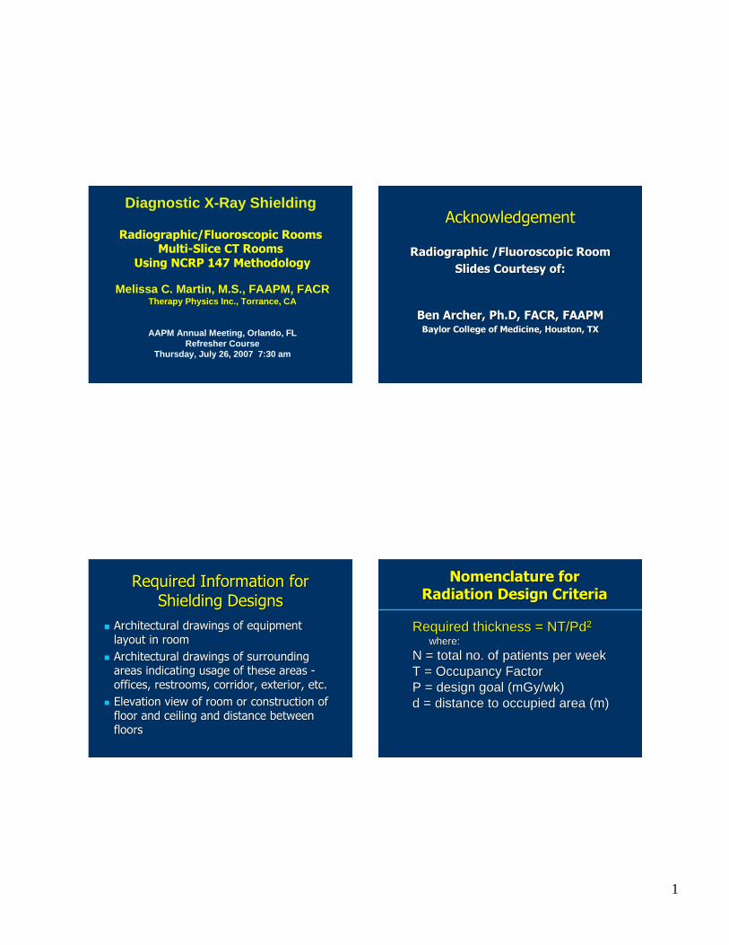
Diagnosti c X-Ray Shie lding
Radiographic/Fluoroscopic RoomsMulti-Slice CT Rooms
Using NCRP 147 Methodology
Diagnosti c X-Ray Shieldi ng
Radiographic/Fluoroscopic RoomsMulti-Slice CT Rooms
Using NCRP 147 Methodology
Meliss a C. Martin, M.S., FAAPM, FACRTherapy Physi cs Inc., Torran ce, CA
AAPM Annual Meeting, Orlando , FLRefresher Course
Thursday, July 26, 2007 7:30 am
Melissa C. Marti n, M.S., FAAPM, FACRTherapy Physics Inc., Torrance, CA
AAPM Annual Meeting, Orland o, FLRefresher Course
Thursday, July 26, 2007 7:30 am
AcknowledgementAcknowledgement
Radiographic /Fluoroscopic Room Radiographic /Fluoroscopic Room Slides Courtesy of:Slides Courtesy of:
Ben Archer, Ben Archer, Ph.DPh.D, FACR, FAAPM, FACR, FAAPMBaylor College of Medicine, Houston, TXBaylor College of Medicine, Houston, TX
Required Information for Required Information for Shielding DesignsShielding Designs
�� Architectural drawings of equipment Architectural drawings of equipment layout in roomlayout in room
�� Architectural drawings of surrounding Architectural drawings of surrounding areas indicating usage of these areas areas indicating usage of these areas --offices, restrooms, corridor, exterior, etc.offices, restrooms, corridor, exterior, etc.
�� Elevation view of room or construction of Elevation view of room or construction of floor and ceiling and distance between floor and ceiling and distance between floorsfloors
Nomenclature for Radiation Design Criteria
Nomenclature for Nomenclature for Radiation Design CriteriaRadiation Design Criteria
Required thickness = NT/PdRequired thickness = NT/Pd22
where:where:
N = total no. of patients per weekN = total no. of patients per weekT = Occupancy FactorT = Occupancy FactorP = design goal (P = design goal (mGymGy/wk)/wk)d = distance to occupied area (m)d = distance to occupied area (m)
2
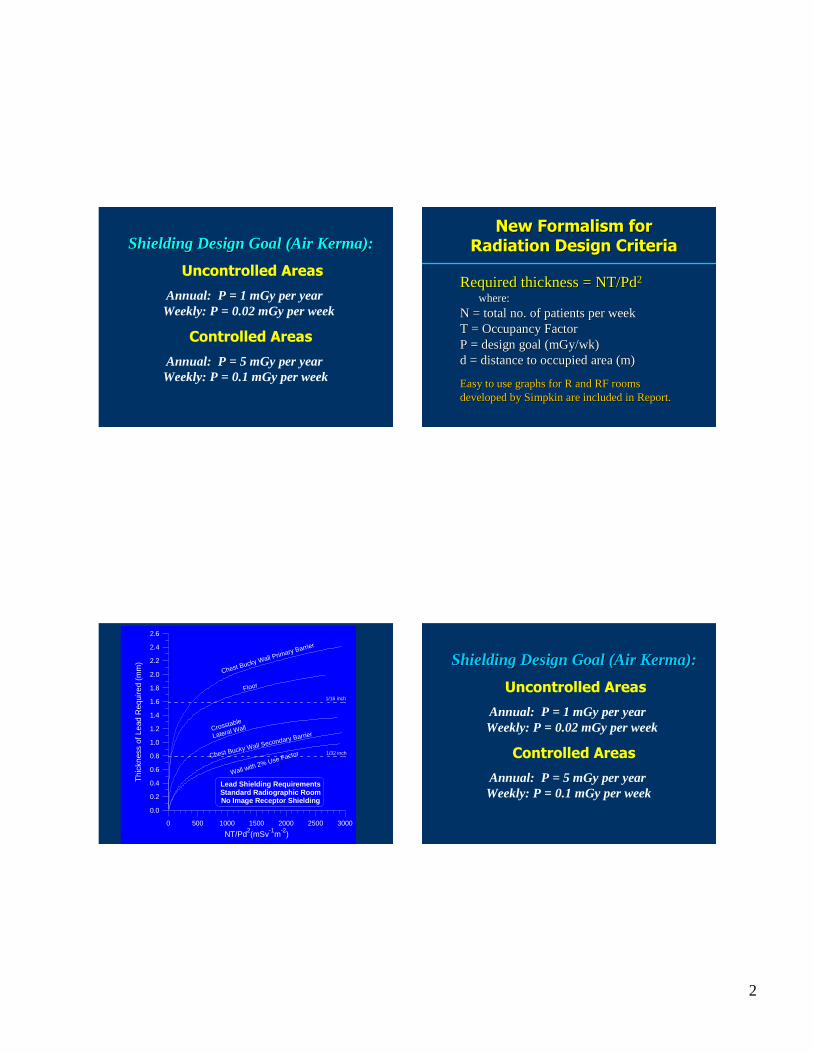
Shielding Design Goal (Air Kerma):
Uncontrolled Areas
Annual: P = 1 mGyper yearWeekly: P = 0.02 mGyper week
Controlled Areas
Annual: P = 5 mGyper yearWeekly: P = 0.1 mGyper week
Shielding Design Goal (AirShielding Design Goal (Air KermaKerma):):
Uncontrolled Areas
Annual: P = 1 mGyper yearWeekly:P = 0.02mGy per week
Controlled Areas
Annual: P = 5 mGyper yearWeekly:P = 0.1mGyper week
New Formalism for Radiation Design Criteria
New Formalism for New Formalism for Radiation Design CriteriaRadiation Design Criteria
Requiredthickness= NT/PdRequiredthickness = NT/Pd22
where:where:N = total no.of patientsperweekN = total no.of patientsperweekT = Occupancy FactorT = Occupancy FactorP = designgoal(P = design goal(mGymGy/wk)/wk)d = distanceto occupiedarea(m)d = distanceto occupiedarea (m)
Easyto usegraphsfor R andRF roomsEasyto usegraphsfor R andRF roomsdevelopedbydevelopedby SimpkinSimpkin are includedin Report.are includedin Report.
0 500 1000 1500 2000 2500 3000
NT/Pd2(mSv-1m-2)
0.0
0.2
0.4
0.6
0.8
1.0
1.2
1.4
1.6
1.8
2.0
2.2
2.4
2.6
Thi
ckne
ssof
Lead
Req
uire
d(m
m)
Lead Shiel ding Require mentsStandard Radiogr aphic RoomNo Image Receptor Shiel ding
Floor
Chest Bucky Wall Primary Barrier
Crosstable
Lateral Wall
Wall with 2% Use FactorChest Bucky Wall Secondary Barrier
1/32 inch
1/16 inch
Shielding Design Goal (Air Kerma):
Uncontrolled Areas
Annual: P = 1 mGyper yearWeekly:P = 0.02mGy per week
Controlled Areas
Annual: P = 5 mGyper yearWeekly:P = 0.1mGyper week
Shielding DesignGoal (AirShielding Design Goal (Air KermaKerma):):
Uncontrolled Areas
Annual: P = 1 mGyper yearWeekly: P = 0.02mGy per week
Controlled Areas
Annual: P = 5 mGyper yearWeekly: P = 0.1mGy per week
3
Distance (d)Distance (d)
The The distance in distance in metersmeters from either from either the primary or secondary radiation the primary or secondary radiation source to the occupied area.source to the occupied area.
New recommendations in Report New recommendations in Report 147 for areas above and below 147 for areas above and below source.source.
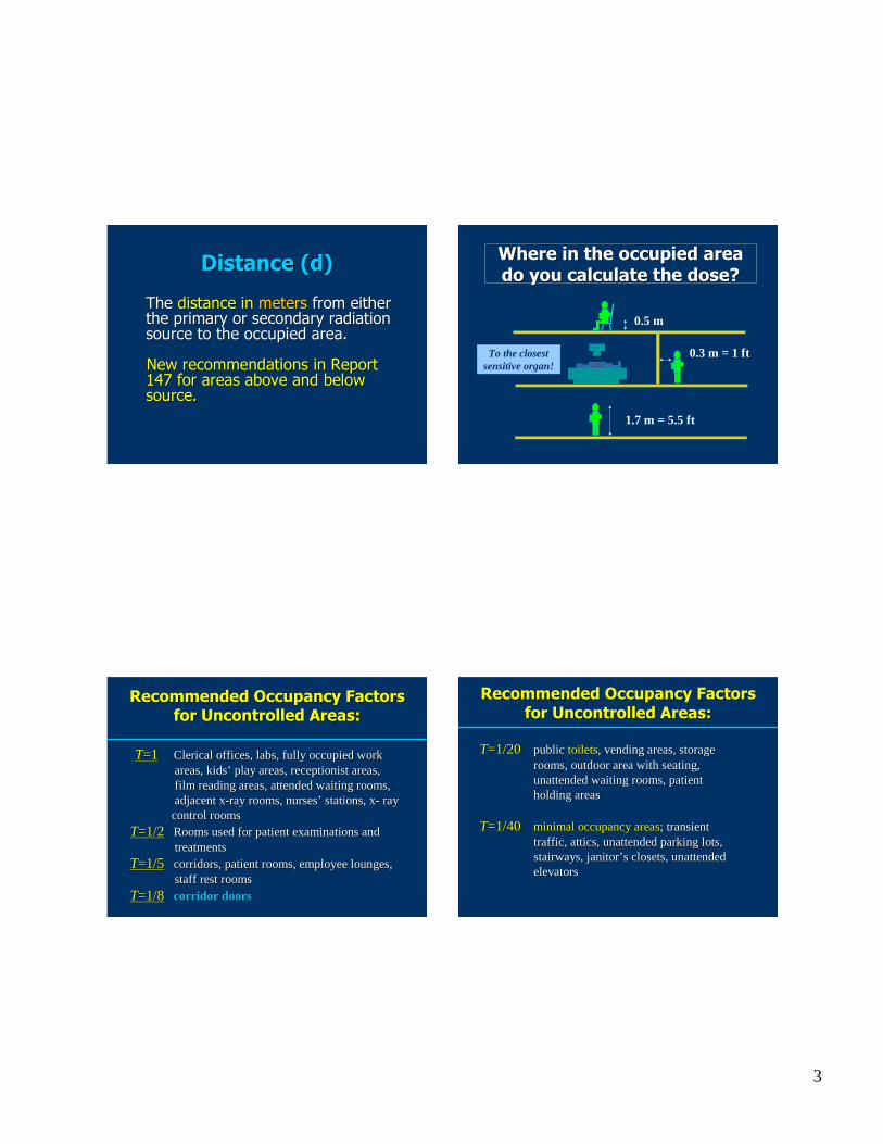
Where in the occupied area Where in the occupied area do you calculate the dose?do you calculate the dose?
1.7 m = 5.5 ft
0.3m = 1 ft
0.5m
To theclosestsensitive organ!
Recommended Occupancy Factors Recommended Occupancy Factors for Uncontrolled Areas:for Uncontrolled Areas:
TT=1=1 Clerical offices, labs, fully occupiedworkClerical offices,labs,fully occupied workareas,kidsareas,kids’’ playareas, receptionist areas,playareas,receptionist areas,fi lm reading areas,attendedwaiting rooms,fi lm readingareas, attendedwaiting rooms,adjacentxadjacentx--ray rooms,nursesray rooms,nurses’’ stations,xstations,x-- rayray
control roomscontrol roomsTT=1/2=1/2 Roomsusedfor patient examinationsandRoomsused for patientexaminationsand
treatmentstreatmentsTT=1/5=1/5 corridors,patient rooms, employeelounges,corridors,patientrooms,employeelounges,
staff restroomsstaff restroomsTT=1/8=1/8 corridor doorscorridor doors
TT=1/20=1/20 publicpublic toiletstoilets, vendingareas,storage, vendingareas,storagerooms,outdoor area with seating,rooms,outdoorareawith seating,unattendedwaiting rooms,patientunattendedwaiting rooms,patientholdingareasholdingareas
TT=1/40=1/40 minimal occupancyareasminimal occupancyareas; transient; transienttraffic, attics,unattendedparking lots,traffic, attics,unattendedparking lots,stairways,janitorstairways,janitor’’ s closets,unattendeds closets,unattendedelevatorselevators
Recommended Occupancy FactorsRecommended Occupancy Factorsfor Uncontrolled Areas:for Uncontrolled Areas:
4
PrePre--shielding shielding ((xxprepre) for ) for Radiographic Room Workload Radiographic Room Workload
Distributions Distributions (Dixon RL, Med Phys 1994)(Dixon RL, Med Phys 1994)
Grid + cassette: (crosstable)Grid + cassette: (crosstable)Equivalentto: 0.3mmEquivalentto: 0.3 mm PbPb
or 3 cm concreteor 3 cm concrete
Grid + cassette + table/chest buckyGrid + cassette + table/chest buckysupports: (overtable andchest)supports:(overtable andchest)Equivalentto: 0.85mmEquivalentto: 0.85 mm PbPb
or 7.2cm concreteor 7.2 cm concrete
Equivalency of Shielding Materials Equivalency of Shielding Materials Table 4.8 Page67Table 4.8 Page67
Steel thicknessrequirement:Steelthicknessrequirement:88 ×× PbPbthicknessrequirementthicknessrequirement
Gypsumwallboardthicknessrequirement:Gypsumwallboardthicknessrequirement:3.23.2 ×× concretethicknessrequirementconcretethicknessrequirement
Plate Glassthicknessrequirement:PlateGlassthicknessrequirement:1.21.2 ×× concretethicknessrequirementconcretethicknessrequirement
LightLight--weightconcretethickness requirement:weight concretethicknessrequirement:1.31.3 ×× stdstd--weight concretethicknessweightconcretethickness
requirementrequirement
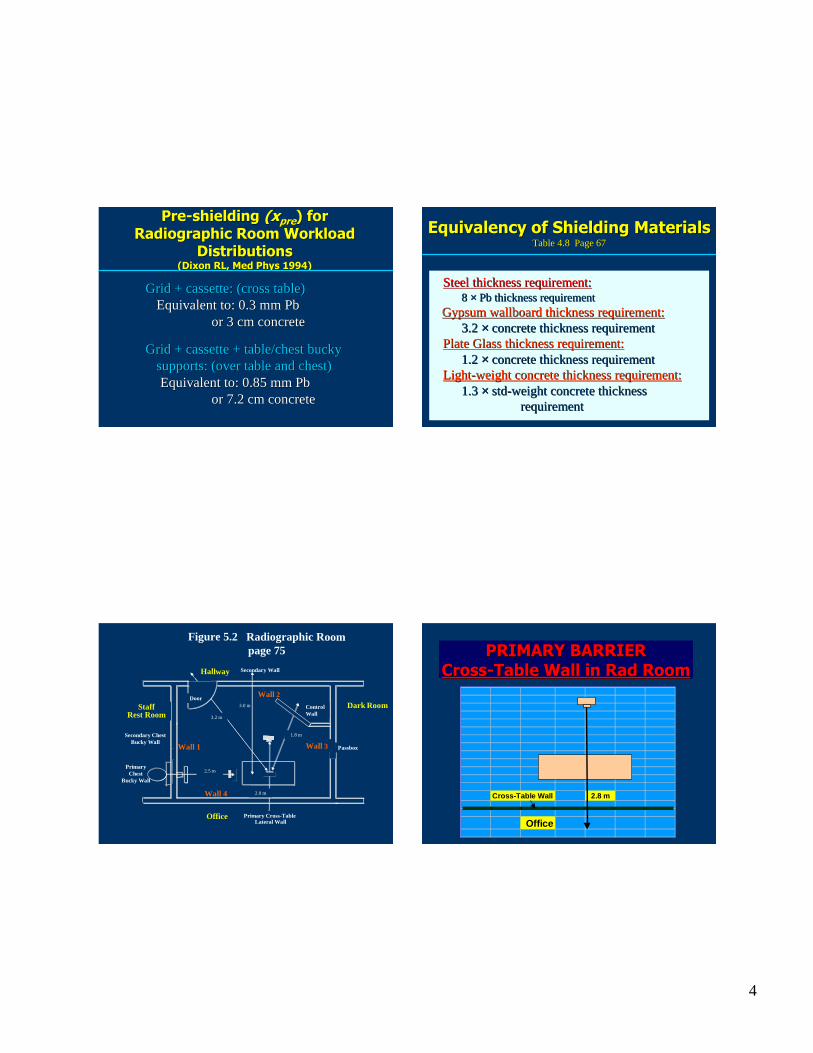
Figure 5.2 Radiographic Roompage 75
Secondary ChestBucky Wall
Wall 2
Wall 4
Secondar y Wall
Pr imar y Cross-TableLateral Wall
Office
3.0 m
Pr imar yChest
Bucky Wall
2.5 m
1.8 m
Wall 3Wall 1
ControlWall
StaffRest Room
Dark Room
2.0 m
Hallway
3.2 m
Door
Passbox
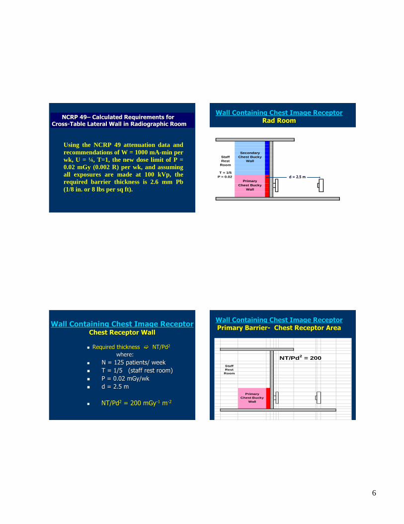
PRIMARY BARRIERPRIMARY BARRIERCrossCross--Table Wall in Table Wall in RadRad RoomRoom
Cross-Table Wall 2.8 m
Office

5
Simplified Graphical SolutionSimplified Graphical SolutionCross-Table Wall in Rad Room
Required thickness NT/Pd2
where:N = 125patients/ weekT = 1P = 0.02mGy/wkd = 2.8m
NT/Pd2 = 797mGy= 797mGy--1 mm--2
Simplified Graphical SolutionSimplifie d Graphical SolutionCross-Table Wall in Rad Room
1. Go to page 54, Fig. 4.5a 1. Go to page 54, Fig. 4.5a (Primary, lead, with no pre(Primary, lead, with no pre--shielding)shielding)
2. Look up NT/Pd2. Look up NT/Pd22 = 797= 797(Cross(Cross--table Wall)table Wall)
PbPb required = 1.03 mmrequired = 1.03 mmSpecify: 4/64Specify: 4/64”” (1/16(1/16””); 4 lb/); 4 lb/sqftsqft
3.02.0 2.5 4.0 5.0 6.0 8.0
Nominal Thickness of Lead (mm and inches) and Nominal Weight (lb ft-2) at bottom of each bar
0.79 mm1/32 inch
1.00 mm5/128 inch
1.19 mm3/64 inc h
1.58 mm1/16 inch
1.98 mm5/64 inch
23
1
2
3 3.17mm1/8 inch
2.38 mm3/32 inch
Nominal Lead Thicknesses Simplifie d Graphical SolutionCross-Table Wall in Rad Room
OROR1. Go to page 55, Fig. 4.5b1. Go to page 55, Fig. 4.5b
(Primary, lead, with pre(Primary, lead, with pre--shielding)shielding)2. Look up NT/Pd2. Look up NT/Pd22 = 797= 797
(Cross(Cross--table Wall)table Wall)
PbPb required = 0.83 mmrequired = 0.83 mmSpecify: 5/128Specify: 5/128””; 2.5 lb/; 2.5 lb/sqftsqft (minimum)(minimum)Recommended: 1/16Recommended: 1/16””; 4 lb/sq ft; 4 lb/sq ft
6
NCRP 49NCRP 49–– Calculated Requirements forCalculated Requirements forCrossCross--Table Lateral Wall in Radiographic RoomTable Lateral Wall in Radiographic Room
Using the NCRP 49 attenuation data andrecommendations of W = 1000mA-min perwk, U = ¼, T=1, the new doselimit of P =0.02 mGy (0.002 R) per wk, and assumingall exposures are made at 100 kVp, therequired barrier thickness is 2.6 mm Pb(1/8 in. or 8 lbs per sq ft) .
Secondar yStaff Chest Buck yRest Wall
Room
T = 1/5P = 0.02
PrimaryChest Bucky
Wall
Wall Containing Chest Image ReceptorWall Containing Chest Image ReceptorRadRad Room Room
d = 2.5 md = 2.5 m
�� Required thickness Required thickness �� NT/PdNT/Pd22
where: where: �� N = 125 patients/ week N = 125 patients/ week �� T = 1/5 (staff rest room)T = 1/5 (staff rest room)�� P = 0.02 P = 0.02 mGymGy/wk/wk�� d = 2.5 md = 2.5 m
�� NT/PdNT/Pd22 = 200 mGy= 200 mGy--11 mm--22
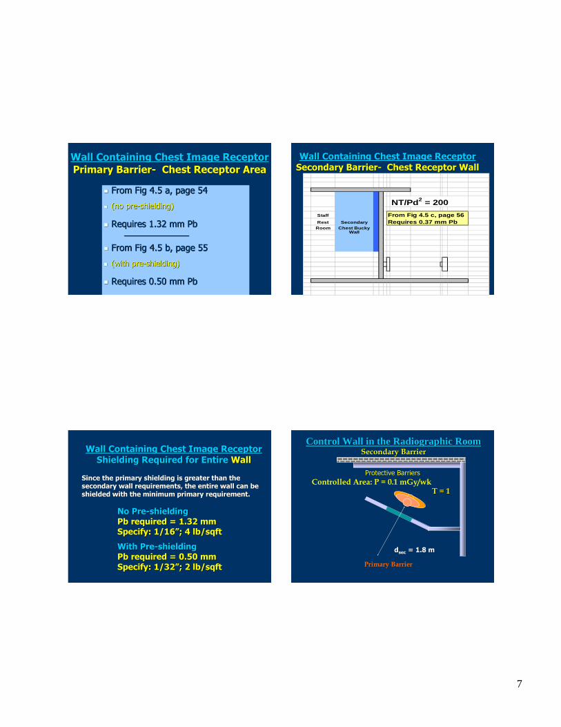
Wall Containing Chest Image ReceptorWall Containing Chest Image ReceptorChest Receptor WallChest Receptor Wall
NT/Pd2 = 200StaffRest
Room
Prim aryChest Bucky
Wall
Wall Containing Chest Image ReceptorWall Containing Chest Image ReceptorPrimary BarrierPrimary Barrier-- Chest Receptor AreaChest Receptor Area
7
Wall Containing Chest Image ReceptorWall Containing Chest Image ReceptorPrimary BarrierPrimary Barrier-- Chest Receptor AreaChest Receptor Area
�� From Fig 4.5 a, page 54From Fig 4.5 a, page 54
�� (no pre(no pre--shielding)shielding)
�� Requires 1.32 mm Requires 1.32 mm PbPb______________________________
�� From Fig 4.5 b, page 55From Fig 4.5 b, page 55
�� (with pre(with pre--shielding) shielding)
�� Requires 0.50 mm Requires 0.50 mm PbPb
NT/Pd2 = 200
Staff Fro m Fig 4.5 c, page 56Rest Secondar y Require s 0.37 mm Pb
Roo m Chest Buc kyWall
Wall Containing Chest Image ReceptorWall Containing Chest Image ReceptorSecondary BarrierSecondary Barrier-- Chest Receptor WallChest Receptor Wall
Wall Containing Chest Image Receptor Wall Containing Chest Image Receptor Shielding Required for EntireShielding Required for Entire WallWall
Since the primary shielding is greater than the Since the primary shielding is greater than the secondary wall requirements, the entire wall can be secondary wall requirements, the entire wall can be shielded with the minimum primary requirement.shielded with the minimum primary requirement.
No PreNo Pre--shieldingshieldingPbPb required = 1.32 mmrequired = 1.32 mmSpecify: 1/16Specify: 1/16””; 4 lb/; 4 lb/sqftsqft
With PreWith Pre--shieldingshieldingPbPb required = 0.50 mmrequired = 0.50 mmSpecify: 1/32Specify: 1/32””; 2 lb/; 2 lb/sqftsqft
Protective BarriersProtective Barriers
Primary Barrier
Contro l Wall in the Radiographic RoomContro l Wall in the Radiographic RoomSecondary BarrierSecondary Barrier
ddsecsec = 1.8 m= 1.8 m
Controlled Area: P = 0.1 mGy/wkT = 1T = 1
8
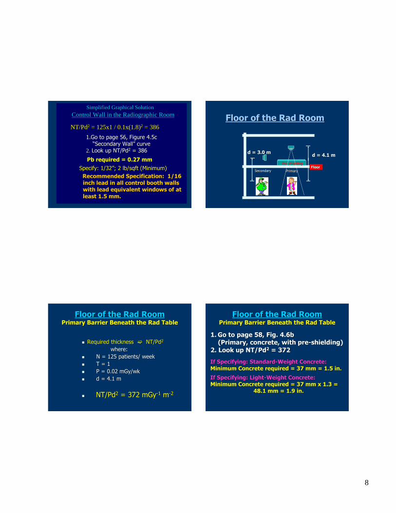
Simplified Graphical SolutionControl Wall in theRadiographicRoom
NT/Pd2 = 125x1 / 0.1x(1.8)2 = 386
1.Go to page 56, Figure 4.5c“Secondary Wall” curve
2. Look up NT/Pd2 = 386
Pb required = 0.27 mmSpecify: 1/32”; 2 lb/sqft (Minimum)Recommended Specification: 1/16 inch lead in all control booth walls with lead equivalent windows of at least 1.5 mm.
Simplified Graphical SolutionSimplified Graphical SolutionControl Wall in theRadiographic RoomControl Wall in theRadiographicRoom
NT/PdNT/Pd22 = 125x1 / 0.1x(1.8)= 125x1/ 0.1x(1.8)22 = 386= 386
1.Go to page 56, Figure 4.5c1.Go to page 56, Figure 4.5c““Secondary WallSecondary Wall”” curvecurve
2.2. Look up NT/PdLook up NT/Pd22 = 386= 386
PbPb required = 0.27 mmrequired = 0.27 mmSpecify: 1/32Specify: 1/32””; 2 lb/; 2 lb/sqftsqft (Minimum)(Minimum)Recommended Specification: 1/16 Recommended Specification: 1/16 inch lead in all control booth walls inch lead in all control booth walls with lead equivalent windows of at with lead equivalent windows of at least 1.5 mm. least 1.5 mm.
Floor of the Floor of the RadRad RoomRoom
d = 4.1 md = 4.1 m
FloorFloorPrimaryPrimarySecondarySecondary
d = 3.0 md = 3.0 m
Pre-shielding
�� Required thickness Required thickness �� NT/PdNT/Pd22
where: where: �� N = 125 patients/ week N = 125 patients/ week �� T = 1T = 1�� P = 0.02 P = 0.02 mGymGy/wk/wk�� d = 4.1 md = 4.1 m
�� NT/PdNT/Pd22 = 372 mGy= 372 mGy--11 mm--22
Floor of the Floor of the RadRad RoomRoomPrimary Barrier Beneath the Primary Barrier Beneath the RadRad TableTable
If Specifying: StandardIf Specifying: Standard--Weight Concrete:Weight Concrete:Minimum Concrete required = 37 mm = 1.5 in.Minimum Concrete required = 37 mm = 1.5 in.
If Specifying: LightIf Specifying: Light--Weight Concrete:Weight Concrete:Minimum Concrete required = 37 mm x 1.3 = Minimum Concrete required = 37 mm x 1.3 =
48.1 mm = 1.9 in.48.1 mm = 1.9 in.
Floor of the Floor of the RadRad RoomRoomPrimary Barrier Beneath the Primary Barrier Beneath the RadRad TableTable
1.1. Go to page 58, Fig. 4.6bGo to page 58, Fig. 4.6b(Primary, concrete, with pre(Primary, concrete, with pre--shielding)shielding)
2. Look up NT/Pd2. Look up NT/Pd22 = 372= 372
9
�� Required thickness Required thickness �� NT/PdNT/Pd22
where: where: �� N = 125 patients/ week N = 125 patients/ week �� T = 1T = 1�� P = 0.02 P = 0.02 mGymGy/wk/wk�� d = 3.0 md = 3.0 m
�� NT/PdNT/Pd22 = 694 mGy= 694 mGy--11 mm--22
Floor of the Floor of the RadRad RoomRoomSecondary Barrier Calculation for FloorSecondary Barrier Calculation for Floor
Minimum Concrete required = 33 mm = 1.3 in.Minimum Concrete required = 33 mm = 1.3 in.
This is less than the 37 mm thickness required This is less than the 37 mm thickness required for the primary barrier. Thus 37 mm of for the primary barrier. Thus 37 mm of standardstandard--weight concrete will suffice for the weight concrete will suffice for the entire floor.entire floor.
Floor of the Floor of the RadRad RoomRoomSecondary Barrier Calculation for FloorSecondary Barrier Calculation for Floor
1.1. Go to page 59, Fig. 4.6c Go to page 59, Fig. 4.6c (Secondary, concrete)(Secondary, concrete)
2. Look up NT/Pd2. Look up NT/Pd22 = 694= 694
Shielding ReferencesShielding References
�� SimpkinSimpkin, DJ, Transmission of scatter radiation from computed , DJ, Transmission of scatter radiation from computed tomography (CT) scanners determined by a Monte Carlo calculationtomography (CT) scanners determined by a Monte Carlo calculation..Health Physics 58(3):363Health Physics 58(3):363--367, 1990.367, 1990.
�� Dixon, RL and Dixon, RL and SimpkinSimpkin, DJ. New Concepts for Radiation Shielding of , DJ. New Concepts for Radiation Shielding of Medical Diagnostic XMedical Diagnostic X--ray Facilities. In Proceedings of the 1997 ray Facilities. In Proceedings of the 1997 AAPM Summer School.AAPM Summer School.
�� NCRP (2005), National Council on Radiation Protection and NCRP (2005), National Council on Radiation Protection and Measurements. Measurements. Structural Shielding Design for Medical XStructural Shielding Design for Medical X--Ray Ray Imaging FacilitiesImaging Facilities, NCRP Report #147 (National Council on Radiation , NCRP Report #147 (National Council on Radiation Protection and Measurements, Bethesda, Maryland)Protection and Measurements, Bethesda, Maryland)
AcknowledgementAcknowledgement
Multi Slice CT Shielding Multi Slice CT Shielding Slides Courtesy of:Slides Courtesy of:
S. Jeff S. Jeff ShephardShephard, M.S., DABR, M.S., DABRM.D. Anderson Cancer Center, Houston, TXM.D. Anderson Cancer Center, Houston, TX
Ben Archer, Ben Archer, Ph.DPh.D, FACR, FACRBaylor College of Medicine, Houston, TXBaylor College of Medicine, Houston, TX
10
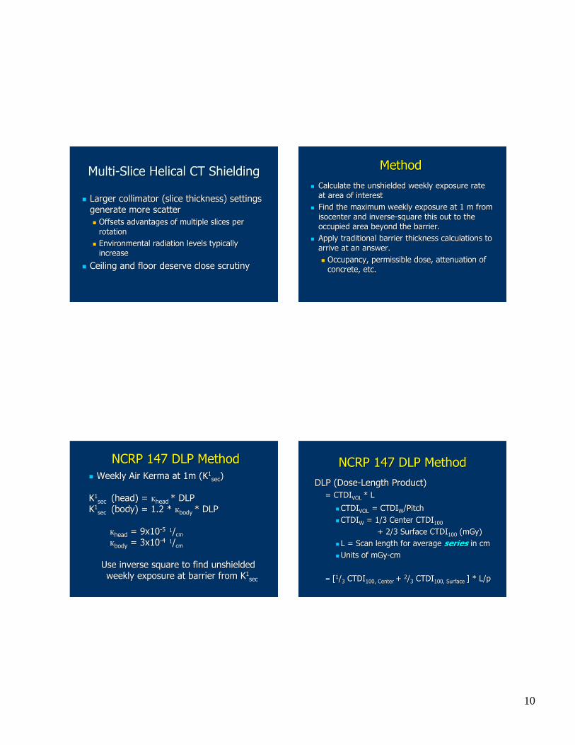
MultiMulti--Slice Helical CT ShieldingSlice Helical CT Shielding
�� Larger collimator (slice thickness) settings Larger collimator (slice thickness) settings generate more scattergenerate more scatter�� Offsets advantages of multiple slices per Offsets advantages of multiple slices per
rotationrotation�� Environmental radiation levels typically Environmental radiation levels typically
increaseincrease
�� Ceiling and floor deserve close scrutinyCeiling and floor deserve close scrutiny
MethodMethod�� Calculate the unshielded weekly exposure rate Calculate the unshielded weekly exposure rate
at area of interest at area of interest �� Find the maximum weekly exposure at 1 m from Find the maximum weekly exposure at 1 m from
isocenterisocenter and inverseand inverse--square this out to the square this out to the occupied area beyond the barrier.occupied area beyond the barrier.
�� Apply traditional barrier thickness calculations to Apply traditional barrier thickness calculations to arrive at an answer.arrive at an answer.�� Occupancy, permissible dose, attenuation of Occupancy, permissible dose, attenuation of
concrete, etc.concrete, etc.
�� Weekly Air Kerma at 1m (KWeekly Air Kerma at 1m (K11secsec))
KK11sec sec (head) = (head) = ккheadhead * DLP* DLP
KK11sec sec (body) = 1.2 * (body) = 1.2 * ккbodybody * DLP* DLP
ккheadhead = 9x10= 9x10--55 11//cmcm
ккbodybody = 3x10= 3x10--44 11//cmcm
Use inverse square to find unshielded Use inverse square to find unshielded weekly exposure at barrier from Kweekly exposure at barrier from K11
secsec
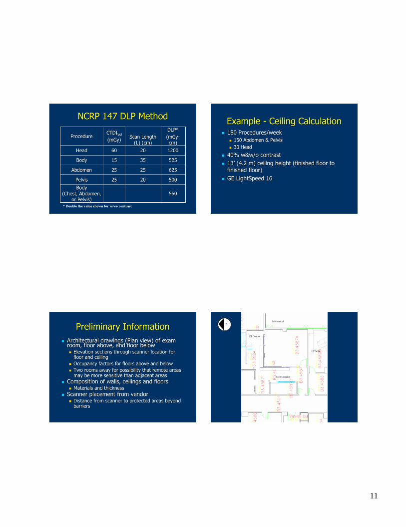
NCRP 147 DLP MethodNCRP 147 DLP Method
DLP (DoseDLP (Dose--Length Product) Length Product) = CTDI= CTDIVOL VOL * L* L
�� CTDICTDIVOLVOL = CTDI= CTDIWW/Pitch/Pitch�� CTDICTDIWW = 1/3 Center CTDI= 1/3 Center CTDI100100
+ 2/3 Surface CTDI+ 2/3 Surface CTDI100100 (mGy)(mGy)�� L = Scan length for average L = Scan length for average seriesseries in cmin cm�� Units of mGyUnits of mGy--cmcm
== [[11//33 CTDICTDI100, Center 100, Center ++ 22//33 CTDICTDI100, Surface 100, Surface ] * L/p] * L/p
NCRP 147 DLP MethodNCRP 147 DLP Method
11
NCRP 147 DLP MethodNCRP 147 DLP Method
550550BodyBody
(Chest, Abdomen, (Chest, Abdomen, or Pelvis)or Pelvis)
50050020202525PelvisPelvis
62562525252525AbdomenAbdomen
52552535351515BodyBody
1200120020206060HeadHead
DLP*DLP*(mGy(mGy--cm)cm)
Scan Length Scan Length (L) (cm)(L) (cm)
CTDICTDIVolVol
(mGy)(mGy)ProcedureProcedure
* Double the value shownfor w/wo contrast
Example Example -- Ceiling CalculationCeiling Calculation�� 180 Procedures/week180 Procedures/week
�� 150 Abdomen & Pelvis150 Abdomen & Pelvis�� 30 Head 30 Head
�� 40% w&w/o contrast40% w&w/o contrast�� 1313’’ (4.2 m) ceiling height (finished floor to (4.2 m) ceiling height (finished floor to
finished floor)finished floor)�� GE GE LightSpeedLightSpeed 1616
Preliminary InformationPreliminary Information�� Architectural drawings (Plan view) of exam Architectural drawings (Plan view) of exam
room, floor above, and floor belowroom, floor above, and floor below�� Elevation sections through scanner location for Elevation sections through scanner location for
floor and ceilingfloor and ceiling�� Occupancy factors for floors above and belowOccupancy factors for floors above and below�� Two rooms away for possibility that remote areas Two rooms away for possibility that remote areas
may be more sensitive than adjacent areas may be more sensitive than adjacent areas �� Composition of walls, ceilings and floorsComposition of walls, ceilings and floors
�� Materials and thicknessMaterials and thickness�� Scanner placement from vendorScanner placement from vendor
�� Distance from scanner to protected areas beyond Distance from scanner to protected areas beyond barriersbarriers
Mechanical
Tech Corridor
CT Control
NN
CT Scan
12
CopyFax
PACS
RIS
RIS
12'
2'
NN
CT6B3.4587a
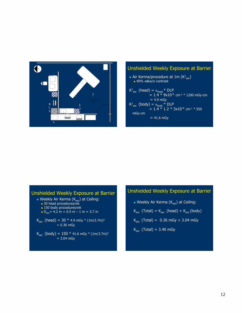
Unshielded Weekly Exposure at BarrierUnshielded Weekly Exposure at Barrier
�� Air Air KermaKerma/procedure at 1m (K/procedure at 1m (K11secsec))
�� 40% w&w/o contrast40% w&w/o contrast
KK11sec sec (head) = (head) = ккheadhead * DLP* DLP
= 1.4 * 9x10= 1.4 * 9x10--55 cmcm--11 * 1200 * 1200 mGymGy--cmcm== 4.9 4.9 mGymGy
KK11sec sec (body) = (body) = ккbodybody * DLP* DLP
= 1.4 * 1.2 * 3x10= 1.4 * 1.2 * 3x10--44 cmcm--11 * 550 * 550 mGymGy--cmcm
== 41.6 41.6 mGymGy
Unshielded Weekly Exposure at BarrierUnshielded Weekly Exposure at Barrier�� Weekly Air Kerma (Weekly Air Kerma (KKsecsec) at Ceiling:) at Ceiling:
�� 30 head procedures/wk30 head procedures/wk�� 150 body procedures/wk150 body procedures/wk�� DDsecsec= 4.2 m + 0.5 m = 4.2 m + 0.5 m –– 1 m = 3.7 m1 m = 3.7 m
KKsecsec (head) = 30 * (head) = 30 * 4.9 4.9 mGymGy * (1m/3.7m)* (1m/3.7m)22
= 0.36 = 0.36 mGymGy
KKsecsec (body) = 150 * (body) = 150 * 41.6 41.6 mGymGy * (1m/3.7m)* (1m/3.7m)22
= 3.04 = 3.04 mGymGy
Unshielded Weekly Exposure at BarrierUnshielded Weekly Exposure at Barrier
�� Weekly Air Kerma (Weekly Air Kerma (KKsecsec) at Ceiling:) at Ceiling:
KKsecsec (Total) = (Total) = KKsecsec (head) + (head) + KKsecsec (body)(body)
KKsecsec (Total) = 0.36 (Total) = 0.36 mGymGy + 3.04 + 3.04 mGymGy
KKsecsec (Total) = 3.40 (Total) = 3.40 mGymGy
13
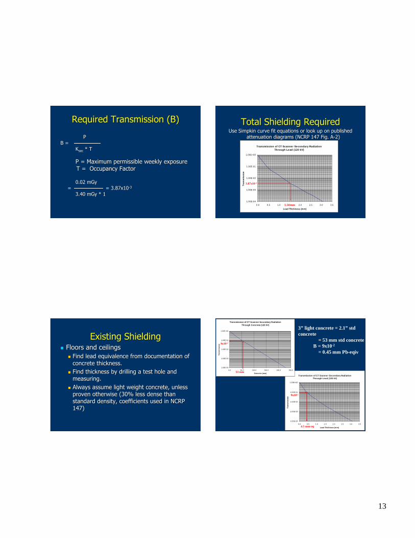
Required Transmission (B)Required Transmission (B)
PPB =B =
KKsecsec * T* T
P = Maximum permissible weekly exposureP = Maximum permissible weekly exposureT = Occupancy FactorT = Occupancy Factor
0.02 0.02 mGymGy== = 3.87x10= 3.87x10--33
3.40 3.40 mGymGy * 1* 1
Total Shielding RequiredTotal Shielding RequiredUse Use SimpkinSimpkin curve fit equations or look up on published curve fit equations or look up on published
attenuation diagrams (NCRP 147 Fig. Aattenuation diagrams (NCRP 147 Fig. A--2)2)
Transmission of CT Scanne r Se condary RadiationThrou gh Le ad (120 kV)
1.00E-04
1.00E-03
1.00E-02
1.00E-01
1.00E+00
0.0 0.5 1.0 1.5 2.0 2.5 3.0 3.5
Lead Thick ness (mm)
Tran
smis
sion
3.87x10⁻³
1.54mm
Existing ShieldingExisting Shielding�� Floors and ceilingsFloors and ceilings
�� Find lead equivalence from documentation of Find lead equivalence from documentation of concrete thickness.concrete thickness.
�� Find thickness by drilling a test hole and Find thickness by drilling a test hole and measuring.measuring.
�� Always assume light weight concrete, unless Always assume light weight concrete, unless proven otherwise (30% less dense than proven otherwise (30% less dense than standard density, coefficients used in NCRP standard density, coefficients used in NCRP 147)147)
Transmission of CT Scanne r Se condary RadiationThrough Le ad (120 kV)
1.00E-04
1.00E-03
1.00E-02
1.00E-01
1.00E+00
0.0 0.5 1.0 1.5 2.0 2.5 3.0 3.5
Lead Thick ness (m m)
Tran
smis
sion
Transmission of CT Scann er Secon dary RadiationThrou gh Concrete (120 kV)
1.00E-04
1.00E-03
1.00E-02
1.00E-01
1.00E+00
0.0 50.0 100.0 150.0 200.0 250.0
Con cre te (mm )
Tran
smis
sion
3” light concrete= 2.1” stdconcrete
= 53mm std concreteB = 9x10-2
= 0.45 mm Pb-eqiv
53 mm
9x10⁻²
4.5 mm-eq
9x10⁻²
14
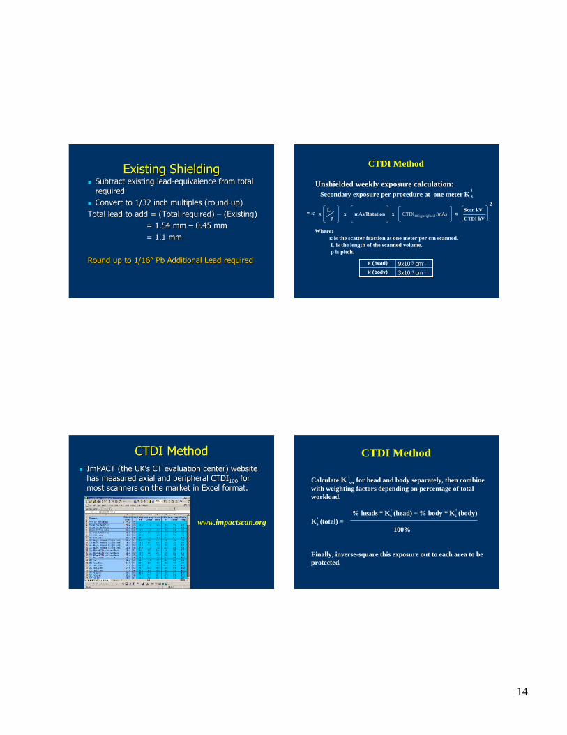
Existing ShieldingExisting Shielding�� Subtract existing leadSubtract existing lead--equivalence from total equivalence from total
requiredrequired�� Convert to 1/32 inch multiples (round up)Convert to 1/32 inch multiples (round up)Total lead to add = (Total required) Total lead to add = (Total required) –– (Existing)(Existing)
= 1.54 mm = 1.54 mm –– 0.45 mm0.45 mm= 1.1 mm= 1.1 mm
Round up to 1/16Round up to 1/16”” PbPb Additional Lead requiredAdditional Lead required
CTDI Method
x CTDI100,peripheral/mAs
Unshielded weekly exposurecalculation:Unshielded weekly exposurecalculation:
= к
Where:к is the scatter fraction at one meter per cm scanned.L is the length of the scanned volume.p is pitch.
x mAs/Rotation
3x103x10--44 cmcm--11К (body)
9x109x10--55 cmcm--11К (head)
Secondary exposureper procedure at onemeter K s1
Scan kV
CTDI kVx
2L
px
CTDI MethodCTDI Method�� ImPACTImPACT (the UK(the UK’’s CT evaluation center)s CT evaluation center) website website
has measured axial and peripheral CTDIhas measured axial and peripheral CTDI100100 for for most scanners on the market in Excel format. most scanners on the market in Excel format.
www.impactscan.org
Calculate K secfor headand body separately, then combinewith weighting factors dependingon percentageof totalworkload.
% heads* K s (head) + % body * K s (body)K s (total) =
100%
Finally, inverse-square this exposureout to eacharea to beprotected.
1
1
1 1
CTDI Method
15
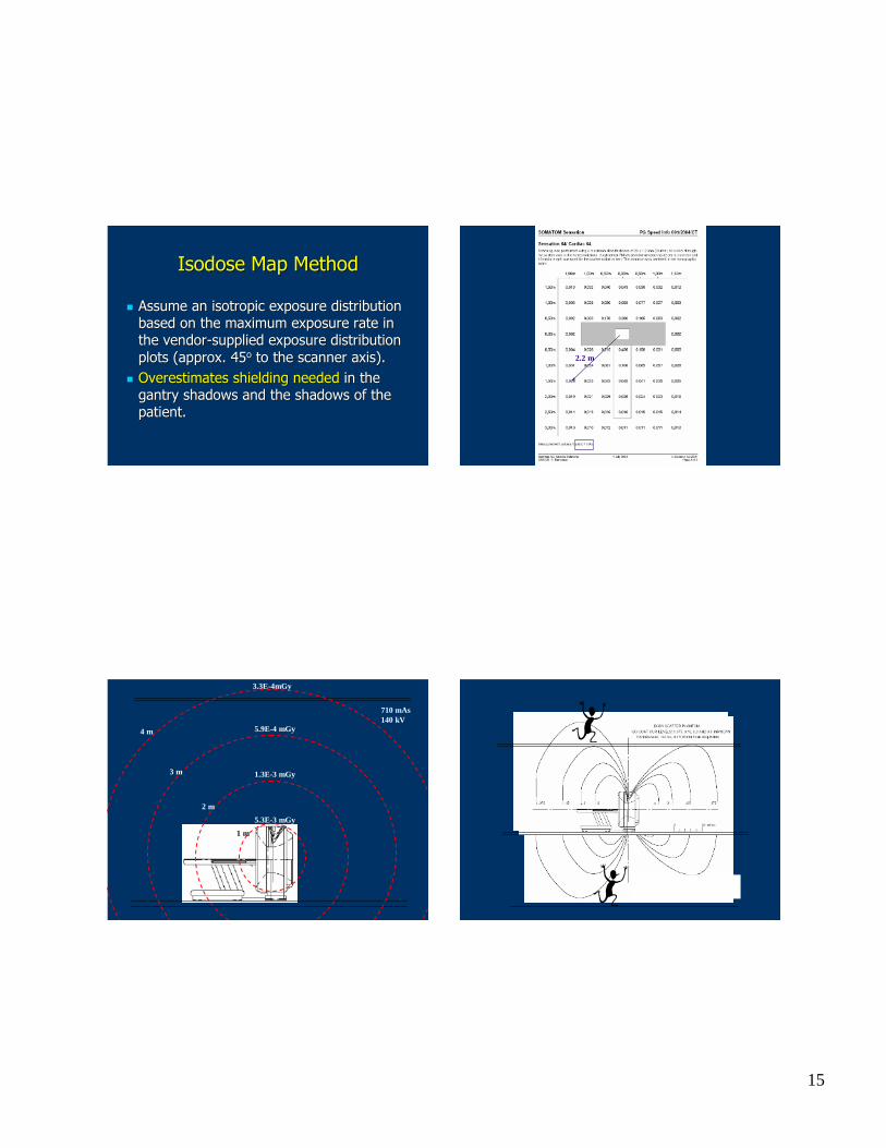
IsodoseIsodose Map MethodMap Method
�� Assume an isotropic exposure distribution Assume an isotropic exposure distribution based on the maximum exposure rate in based on the maximum exposure rate in the vendorthe vendor--supplied exposure distribution supplied exposure distribution plots (approx. 45plots (approx. 45oo to the scanner axis).to the scanner axis).
�� Overestimates shielding neededOverestimates shielding needed in the in the gantry shadows and the shadows of the gantry shadows and the shadows of the patient.patient.
2.2 m
1.3E-3 mGy
5.9E-4 mGy
5.3E-3 mGy
710 mAs140 kV
3.3E-4mGy
1 m
4 m
3 m
2 m
16
8th floor
Acceptable exposuresoutsideof this line
9’
7th floor
Lead
Lead
12'
DropCeiling
Lead
Lead
0.5m aff
Acceptableexposuresoutsideof this line
6th floor
7th floor
6’
Led
6 FeetAFF (below)
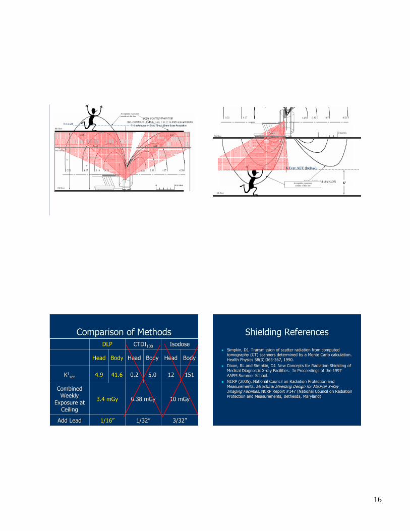
Comparison of MethodsComparison of Methods
10 10 mGymGy0.38 0.38 mGymGy3.4 3.4 mGymGy
Combined Combined Weekly Weekly
Exposure at Exposure at CeilingCeiling
3/323/32””1/321/32””1/161/16””Add LeadAdd Lead
0.20.2
HeadHead
CTDICTDI100100
5.05.0
BodyBody
151151121241.641.64.94.9KK11secsec
BodyBodyHeadHeadBodyBodyHeadHead
IsodoseIsodoseDLPDLP
Shielding ReferencesShielding References
�� SimpkinSimpkin, DJ, Transmission of scatter radiation from computed , DJ, Transmission of scatter radiation from computed tomography (CT) scanners determined by a Monte Carlo calculationtomography (CT) scanners determined by a Monte Carlo calculation..Health Physics 58(3):363Health Physics 58(3):363--367, 1990.367, 1990.
�� Dixon, RL and Dixon, RL and SimpkinSimpkin, DJ. New Concepts for Radiation Shielding of , DJ. New Concepts for Radiation Shielding of Medical Diagnostic XMedical Diagnostic X--ray Facilities. In Proceedings of the 1997 ray Facilities. In Proceedings of the 1997 AAPM Summer School.AAPM Summer School.
�� NCRP (2005), National Council on Radiation Protection and NCRP (2005), National Council on Radiation Protection and Measurements. Measurements. Structural Shielding Design for Medical XStructural Shielding Design for Medical X--Ray Ray Imaging FacilitiesImaging Facilities, NCRP Report #147 (National Council on Radiation , NCRP Report #147 (National Council on Radiation Protection and Measurements, Bethesda, Maryland)Protection and Measurements, Bethesda, Maryland)