Embed Size (px)
Citation preview
Requirements Analysis
Chapter 5

Overview of Analysis
• Producing an analysis model of the system– Correct– Complete– Consistent– Verifiable
Analysis
functionalmodel
nonfunctionalrequirements
analysis objectmodel
Requirementselicitation
dynamic model
Requirements
Analysis Model
Specification
System design
Object design
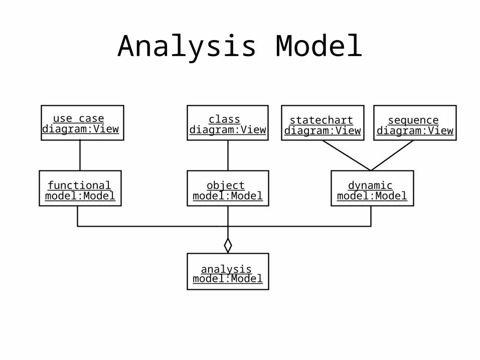
Analysis Model
analysismodel:Model
dynamicmodel:Model
objectmodel:Model
functionalmodel:Model
use casediagram:View
classdiagram:View
statechartdiagram:View
sequencediagram:View
Analysis Classes
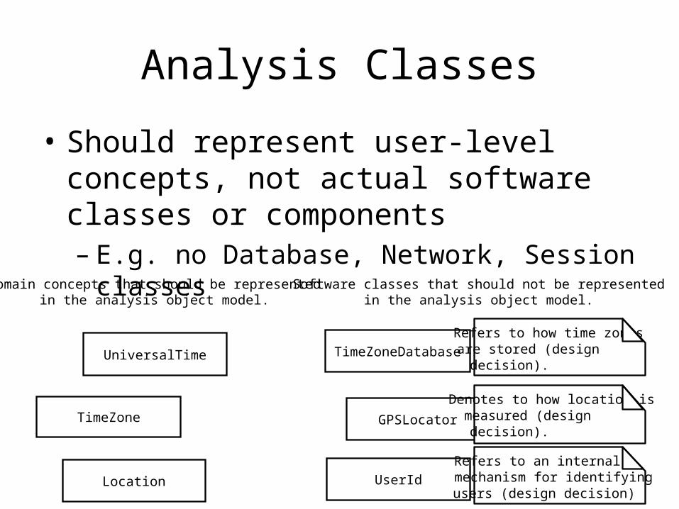
• Should represent user-level concepts, not actual software classes or components– E.g. no Database, Network, Session classes
UniversalTime
TimeZone
Location
TimeZoneDatabase
GPSLocator
UserId
Software classes that should not be representedin the analysis object model.
Domain concepts that should be representedin the analysis object model.
Refers to how time zones are stored (design decision).
Denotes to how location is measured (design decision).
Refers to an internalmechanism for identifyingusers (design decision)

Entity, Boundary, Control Objects
• Entity objects– Represent persistent information tracked by the system
• Boundary objects– Represent the interactions between actors and the system
• Control objects– Represent the system that manages and controls a use case,
tying information together
• Three object approach– Leads to models resilient to change; the interface (boundary
objects) is more likely to change than basic functionality (control and entity objects)

Analysis Classes for Two Button Watch
<<entity>>Year
<<entity>>Month
<<entity>>Day
<<control>>ChangeDateControl
<<boundary>>LCDDisplayBoundary
<<boundary>>ButtonBoundary
<<Meta-Data>> - angle brackets store meta-data
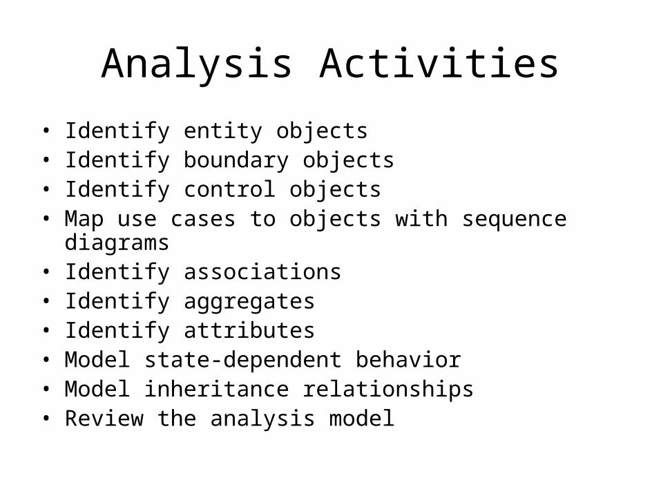
Analysis Activities
• Identify entity objects• Identify boundary objects• Identify control objects• Map use cases to objects with sequence diagrams• Identify associations• Identify aggregates• Identify attributes• Model state-dependent behavior• Model inheritance relationships• Review the analysis model
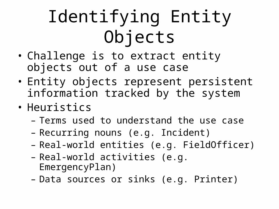
Identifying Entity Objects
• Challenge is to extract entity objects out of a use case
• Entity objects represent persistent information tracked by the system
• Heuristics– Terms used to understand the use case– Recurring nouns (e.g. Incident)– Real-world entities (e.g. FieldOfficer)– Real-world activities (e.g. EmergencyPlan)– Data sources or sinks (e.g. Printer)
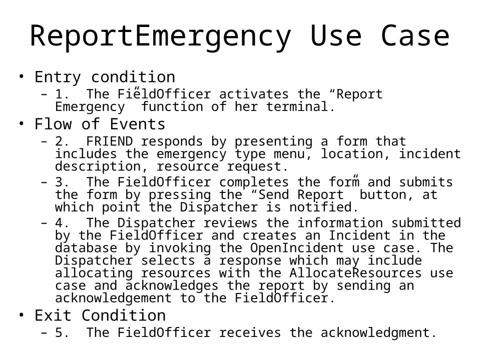
ReportEmergency Use Case• Entry condition
– 1. The FieldOfficer activates the “Report Emergency” function of her terminal.
• Flow of Events– 2. FRIEND responds by presenting a form that includes the
emergency type menu, location, incident description, resource request.
– 3. The FieldOfficer completes the form and submits the form by pressing the “Send Report” button, at which point the Dispatcher is notified.
– 4. The Dispatcher reviews the information submitted by the FieldOfficer and creates an Incident in the database by invoking the OpenIncident use case. The Dispatcher selects a response which may include allocating resources with the AllocateResources use case and acknowledges the report by sending an acknowledgement to the FieldOfficer.
• Exit Condition– 5. The FieldOfficer receives the acknowledgment.

Entity Objects for the ReportEmergency Use Case
• Dispatcher– Police officer who manages incidents. A dispatcher opens,
documents, and closes incidents in response to EmergencyReports with FieldOfficers. Dispatchers are identified by batch numbers.
• EmergencyReport– Initial report about an Incident from a FieldOfficer to a Dispatcher.
An EmergencyReport is composed of an emergency level, a type, a location, description, and resource request.
• FieldOfficer– Police or fire officer on duty. FieldOfficers are identified by badge
numbers.• Incident
– Situation requiring attention from a FieldOfficer. An Incident may be reported in the system by a FieldOfficer or anybody else external to the system. An Incident is composed of a description, response, status, location, and a number of FieldOfficers.
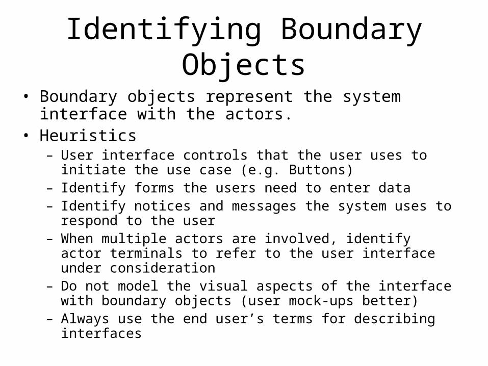
Identifying Boundary Objects
• Boundary objects represent the system interface with the actors.
• Heuristics– User interface controls that the user uses to initiate the use case
(e.g. Buttons)– Identify forms the users need to enter data– Identify notices and messages the system uses to respond to the
user– When multiple actors are involved, identify actor terminals to refer
to the user interface under consideration– Do not model the visual aspects of the interface with boundary
objects (user mock-ups better)– Always use the end user’s terms for describing interfaces
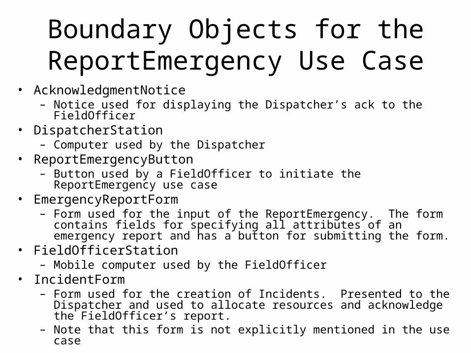
Boundary Objects for the ReportEmergency Use Case
• AcknowledgmentNotice– Notice used for displaying the Dispatcher’s ack to the FieldOfficer
• DispatcherStation– Computer used by the Dispatcher
• ReportEmergencyButton– Button used by a FieldOfficer to initiate the ReportEmergency use case
• EmergencyReportForm– Form used for the input of the ReportEmergency. The form contains fields
for specifying all attributes of an emergency report and has a button for submitting the form.
• FieldOfficerStation– Mobile computer used by the FieldOfficer
• IncidentForm– Form used for the creation of Incidents. Presented to the Dispatcher and
used to allocate resources and acknowledge the FieldOfficer’s report.– Note that this form is not explicitly mentioned in the use case

Identifying Control Objects
• Responsible for coordinating boundary and entity objects– Sequencing of forms or dispatching
information
• Heuristics– Identify one control object per actor in the use
case– Lifespan of a control object should cover the
extent of the use case or the extent of a user session
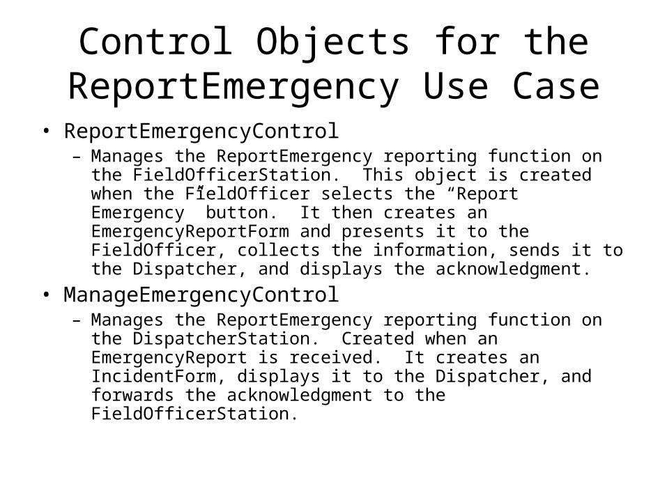
Control Objects for the ReportEmergency Use Case
• ReportEmergencyControl– Manages the ReportEmergency reporting function on the
FieldOfficerStation. This object is created when the FieldOfficer selects the “Report Emergency” button. It then creates an EmergencyReportForm and presents it to the FieldOfficer, collects the information, sends it to the Dispatcher, and displays the acknowledgment.
• ManageEmergencyControl– Manages the ReportEmergency reporting function on the
DispatcherStation. Created when an EmergencyReport is received. It creates an IncidentForm, displays it to the Dispatcher, and forwards the acknowledgment to the FieldOfficerStation.
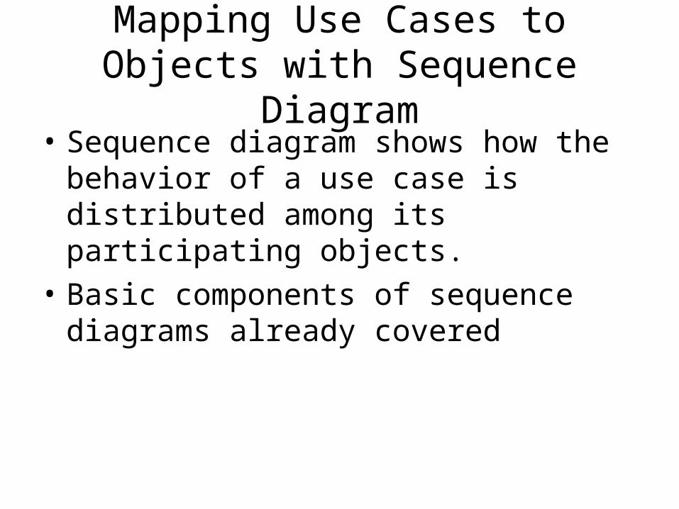
Mapping Use Cases to Objects with Sequence Diagram
• Sequence diagram shows how the behavior of a use case is distributed among its participating objects.
• Basic components of sequence diagrams already covered
Sequence diagram for the ReportEmergency use case.
FieldOfficer
ReportEmergencyButton
ReportEmergencyControl
ReportEmergencyForm
EmergencyReport
ManageEmergencyControl
press()
«create»
«create»
submit()
fillContents()
submitReport()
submitReportToDispatcher()
«create»
«destroy»
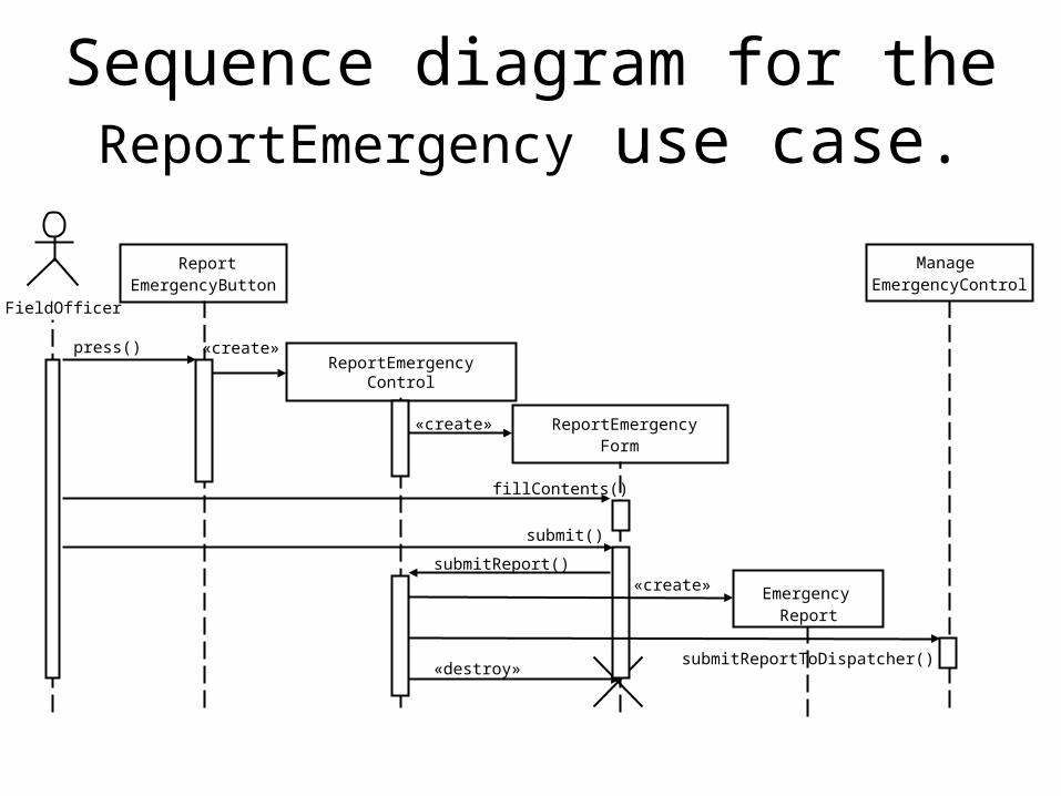
Sequence diagram for the ReportEmergency use case (continued from previous)
IncidentForm
Incident
Acknowledgment
createIncident()
submit()
ManageEmergencyControl
submitReportToDispatcher()
«create»
«create»
«create»
«destroy»
Dispatcher
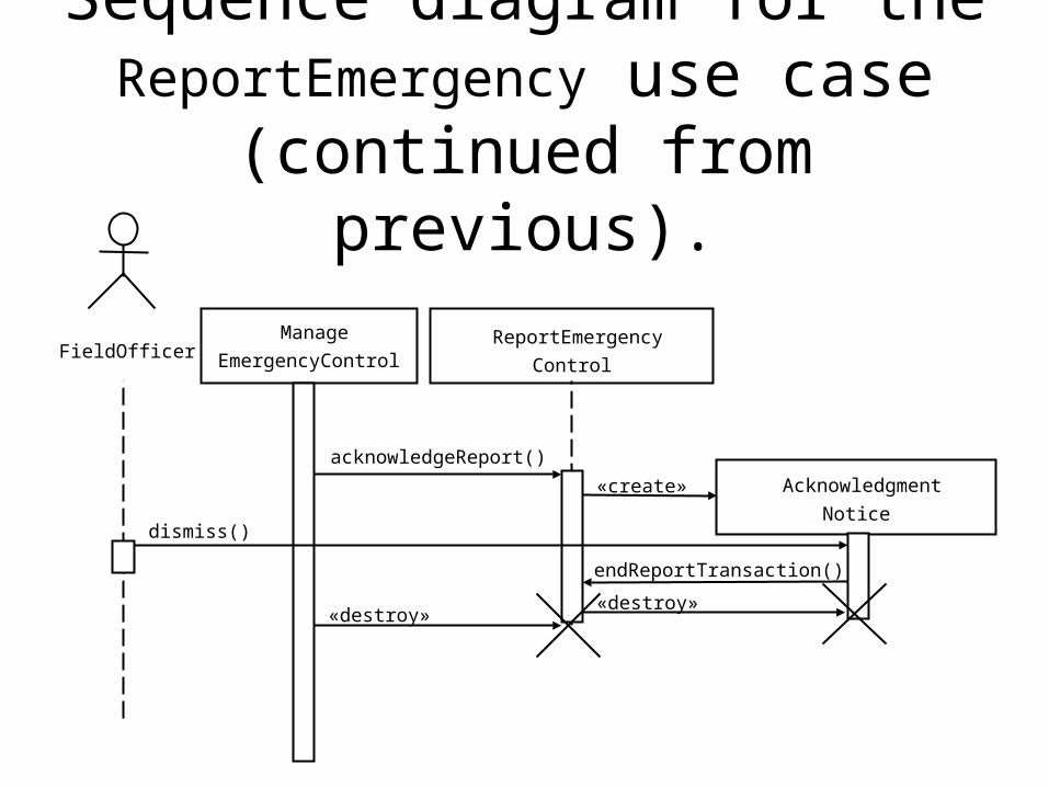
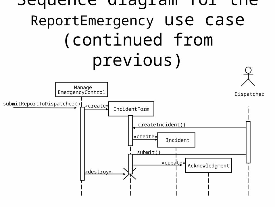
Sequence diagram for the ReportEmergency use case (continued from previous).
FieldOfficer ReportEmergency
Control
Acknowledgment
Notice
Manage
EmergencyControl
dismiss()
acknowledgeReport()
«create»
endReportTransaction()
«destroy»«destroy»
What’s in an Acknowledgment Notice?
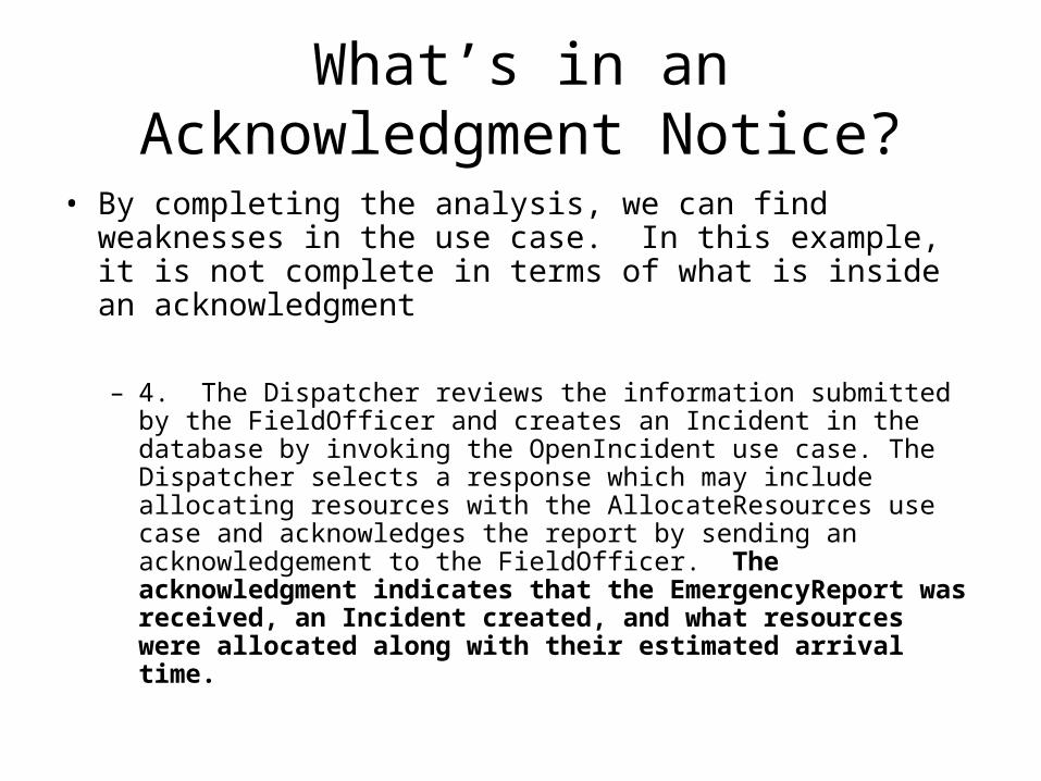
• By completing the analysis, we can find weaknesses in the use case. In this example, it is not complete in terms of what is inside an acknowledgment
– 4. The Dispatcher reviews the information submitted by the FieldOfficer and creates an Incident in the database by invoking the OpenIncident use case. The Dispatcher selects a response which may include allocating resources with the AllocateResources use case and acknowledges the report by sending an acknowledgement to the FieldOfficer. The acknowledgment indicates that the EmergencyReport was received, an Incident created, and what resources were allocated along with their estimated arrival time.

Identifying Associations
• Associations show the relationship among classes
• Heuristics– Examine verb phrases– Name associations and roles precisely– Use qualifiers to identify namespaces and key
attributes– Eliminate any association that can be derived from
other associations– Do not worry about multiplicity until the set of
associations is stable– Too many associations make a model unreadable
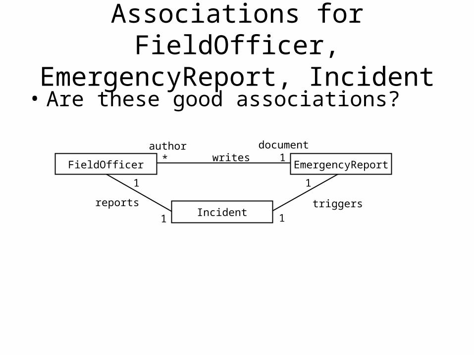
Associations for FieldOfficer, EmergencyReport, Incident
• Are these good associations?
* 1writesauthor document
1
11
1
triggersreports
FieldOfficer EmergencyReport
Incident

Identifying Aggregates
• Whole-part relationships• Heuristics
– Look for whole-part relationships
• If you’re not sure that the association is whole-part, it is better to model it as a one-to-many association and revisit it later when you have a better understanding of the domain

Sample Aggregates
State
County
Township
FireStation
FireFighter
FireEngine
LeadCar
Ambulance
Identifying Attributes
• Attributes are properties of individual objects• Heuristics
– Examine possessive phrases– Represent stored state as an attribute of the entity
object– Describe each attribute– Do not represent an attribute as an object; use an
association instead– Do not waste time describing fine details until the
object structure is stable
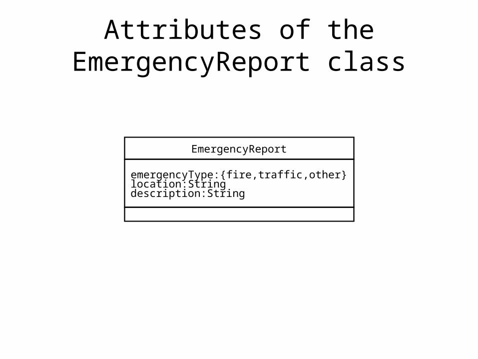
Attributes of the EmergencyReport class
EmergencyReport
emergencyType:{fire,traffic,other}location:Stringdescription:String
Modeling State-Dependent Behavior of Objects
• Sequence diagrams are used to identify operations from the perspective of a use case
• Statechart diagrams represent behavior better from the perspective of a single object
• Basic components of statecharts previously discussed
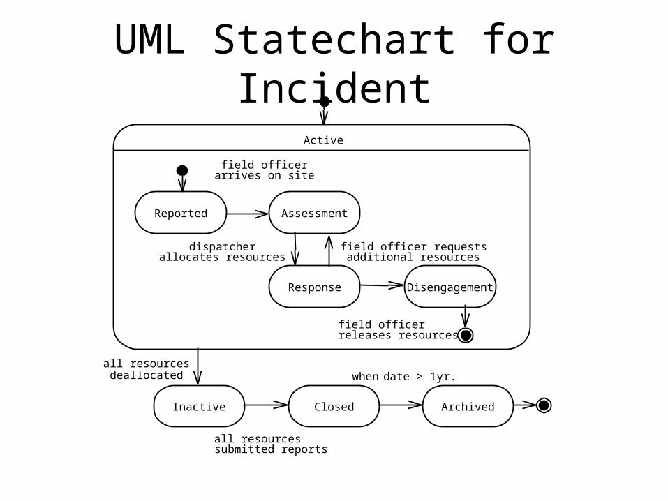
UML Statechart for Incident
Active
Inactive Closed Archived
all
when d ate > 1yr.
resourcessubmitted reports
Reported Assessment
DisengagementResponse
field officerarrives on site
field officerreleases resources
dispatcherallocates resources
field officer requestsadditional resources
all resourcesdeallocated

Modeling Inheritance Relationships
• Generalization helps eliminate redundancy
• Introduce a base or abstract class
• Heuristics– Look for similarities among classes– Look for classes that share the same
attributes
FieldOfficer Dispatcher
PoliceOfficer
badgeNumber:Integer
Reviewing the Analysis Model
• The analysis model is seldom correct or complete on the first pass! Several iterations with the client and user likely necessary
• The model is stable when the number of changes to the model are minimal– Reviewed by developers first, then jointly by
developers and the client– Goal is to ensure specification is correct,
complete, consistent, and unambiguous
Sample Questions from 5.4.11
• Correctness– Is the glossary of entity objects understandable by the user?– Are all error cases described and handled?
• Complete– For each object: In which case is it created? Modified?
Destroyed? Can it be accessed from a boundary object?– For each attribute: What is its type? Qualifier?
• Consistent– Are there multiple classes or use cases with the same name?– Are there objects with similar attributes that are not in the same
generalization hierarchy?• Realistic
– Any novel features in the system? Studies to ensure feasibility?– Can performance and reliability requirements be met?

Reviewmodel
Consolidatemodel
Defineinteractions
Defineassociations
Defineattributes
Definenontrivialbehavior
Defineuse cases
Defineparticipating
objects
Defineboundaryobjects
Definecontrolobjects
Defineentity
objects
Managing Analysis
• Elicitation and analysis activities should be documented in the Requirements Analysis Document– This includes the object models and dynamic models
• Assign responsibilities– Analyst
• Application domain experts; may have individuals for different use cases
– Architect• Unifies use case and object models from a system perspective
– Document editor• Low-level integration of the document and formatting
– Configuration manager• Maintain revision history of document; use computer tools
– Reviewer• Validates the RAD for correctness, completeness, consistency, clarity
Managing Analysis
• Communicating Analysis– Define clear territories– Define clear objectives and success criteria– Brainstorm
• Iterating over the Analysis Model– Brainstorming– Solidification– Maturity
• Client Sign-Off– Represents acceptance of the analysis model by the client– Also agree on
• List of priorities, revision process, list of criteria that will be used to accept or reject the system, schedule and budget
– Prioritization of functions