Embed Size (px)
Citation preview
Requirements and Specifications for the Instrumentation and
Measurement Systems for GENI GENI: Global Environment for Network Innovations May 11, 2009
Status: Draft (Version 0.2) Note to the reader: this document is a work in progress and continues to evolve rapidly. Certain aspects of the instrumentation and measurement systems are not yet fully specified, and, for those aspects that are addressed here, a number of unresolved issues are identified in the text. Further, due to the active development and editing process, some portions of the document may be logically inconsistent with others.
Instrumentation and Measurement Systems for GENI - Specification May 11, 2009
- 2 -
This document has been prepared by the GENI Instrumentation and Measurement Team, but includes contributions and input from others outside of the core team. Core team members:
Paul Barford, University of Wisconsin Mike Blodgett, University of Wisconsin Mark Crovella, Boston University Joel Sommers, Colgate University
Additional contributions: TBD
Instrumentation and Measurement Systems for GENI - Specification May 11, 2009
- 3 -
Revision History:
Version Changes log Date v0.1 Original version – specifies the
basic framework for measurement systems
2/17/09
V0.2 Updates to Section 4 Corrections througout
5/11/09
Instrumentation and Measurement Systems for GENI - Specification May 11, 2009
- 4 -
Table of Contents
Revision History: ......................................................................................................... 31 Document Overview............................................................................................... 52 Design and Process Overview................................................................................. 7
2.1 Instrumentation and Measurement System Requirements ..........................72.2 Design Components ..................................................................................82.3 Design Exclusions ...................................................................................102.4 Development Process ..............................................................................10
3 Instrumentation ................................................................................................... 123.1 Subsystem Components ..........................................................................12
3.1.1 Link Sensors.............................................................................................123.1.2 Time sensors............................................................................................133.1.3 Packet processing device ..........................................................................133.1.4 Instrumentation host ................................................................................13
3.2 Functional Requirements .........................................................................143.2.1 Basic functionality ....................................................................................143.2.2 Transformation functionality ....................................................................15
3.3 Subsystem basic design...........................................................................163.4 Deployment Scenarios .............................................................................173.5 Interfaces to other subsystems................................................................18
3.5.1 Control interface interaction.....................................................................183.5.2 Repository subsystem interaction .............................................................19
4 Data Archive ........................................................................................................ 204.1 Repository...............................................................................................204.2 Data Catalog ...........................................................................................21
5 Interfaces ............................................................................................................ 225.1 Interface components..............................................................................22
6 Security and Access Control ................................................................................. 317 Evaluation and test .............................................................................................. 32
7.1 Tests for the Instrumentation Component ...............................................327.1.1 Functional Tests .......................................................................................327.1.2 Performance Tests....................................................................................33
7.2 Tests for the Data Repository Component ...............................................337.2.1 Functional Tests .......................................................................................337.2.2 Performance Tests....................................................................................33
7.3 Tests for the Interface Component ..........................................................337.3.1 Functional Tests .......................................................................................347.3.2 Performance Tests....................................................................................34
7.4 Tests for the Access Control Component .................................................347.4.1 Functional Tests .......................................................................................347.4.2 Performance Tests....................................................................................34
8 References........................................................................................................... 35
Instrumentation and Measurement Systems for GENI - Specification May 11, 2009
- 5 -
1 Document Overview This document describes the requirements and functional capabilities for an initial set of systems that will be used to specify, gather, analyze and store measurements of experiments conducted in the GENI testbed infrastructure. The initial instrumentation and measurement capabilities described in this document are not intended to be comprehensive or complete. Rather, they represent a first step in a process of developing instrumentation, measurement, analysis and data archival capabilities that support the objectives of the overall GENI mission, the operation of the facility and the study of the GENI infrastructure as an artifact. This document borrows heavily from the GENI Instrumentation and Measurement Systems (GIMS) Specification GDD-06-012. That document specifies a broad vision for instrumentation and measurement and discusses the trade-offs and challenges for different types of instrumentation and measurement. This document describes a measurement capability that is much more limited in scope and specific to the goal of deploying a functional measurement capability in the infrastructure by October 2011 (current expiration data for funding of the grant supporting this work). Any instrumentation, measurement or analysis capability that is not specifically addressed in this document will not be included in the functionality that will be available by the 2011 target. Finally, while initial versions of this document focus on a specific set of functional capabilities and the interface to a specific control framework, the document may well expand in scope (not just detail) over time. The initial version of this document has been created by the Instrumentation and Measurement for GENI team listed on page 2. While comments and contributions from others over time are expected and welcome, the process of maintaining this document will remain with the core team. Since some many aspects of GENI’s architecture and implementation and the measurement system’s requirements are incompletely specified at this time and will likely evolve over time, this document will similarly evolve to maintain consistency with the other systems. The core team will publish updates to this document to reflect any significant change required for consistency with other GENI documents or new functionality that has been developed and deployed. However, the focus of this document will continue to be limited to requirements and functional capabilities of the measurement systems. The implication is that related documents such as user guides or white papers that describe implementation details are likely to emerge over time and will then be referenced by this document. The remainder of this document is organized as follows. Section 2 provides an overview description of the design of the instrumentation and measurement infrastructure and the process for invoking and using these systems in experiments. Section 3 describes the design of the physical instrumentation systems that will be deployed in the GENI infrastructure and gather data from experiments. Section 4 describes the design of the archival systems that will store data from experiments and are accessed by users. Section 5 describes the interfaces that enable instrumentation and measurement systems to be specified in experiments. In Section 6 the design of the security and access control for measurement systems is described. The methods, tools and configurations for test and evaluation of the instrumentation systems are

Instrumentation and Measurement Systems for GENI - Specification May 11, 2009
- 6 -
described in Section 7. A bibliography of references in this document is provided in Section 8.
Instrumentation and Measurement Systems for GENI - Specification May 11, 2009
- 7 -
2 Design and Process Overview The primary objective of the design and development of the instrumentation and measurement systems developed for and deployed in GENI is to ensure that they are sufficient to support a broad spectrum of experiments. However, in contrast to the GIMS GDD-06-12 document, the objective of the initial set of instrumentation and measurement systems for GENI is restricted in scope and more specific in focus in order to ensure that sufficient capability is available and operational in a timely fashion. To that end, the specific focus for the measurement systems described below is on passive packet capture in GENI. By passive packet capture, we mean the ability to gather, save and analyze packets from taps on links in the GENI infrastructure. The motivation for this focus is that passive packet capture enables a broad range of network research experiments and network operations activities. These include experiments with new networking protocols, experiments in network security, experiments with new network applications, experiments with new measurement tools, etc. From a network operations perspective, passive packet capture enables network performance tuning and network troubleshooting. Passive packet capture is seen as an essential complement to other forms of instrumentation and measurement that are possible in GENI including application or protocol instrumentation on end hosts and instrumentation built into the networking devices that will be deployed in GENI. An example of application instrumentation on end hosts is data logging functionality (e.g., web server logs), which is typically specific to an experiment. An example of device instrumentation is a MIB that tracks system specific behaviors such as CPU or memory utilization. While the specifics of application and device instrumentation will vary, we envision that both will be able to eventually take advantage of (at least) the data archival (Section 4) and user interface (Section 5) developed in this project.
2.1 Instrumentation and Measurement System Requirements The general requirements of the instrumentation and measurement systems include (a number borrowed from GDD-06-012):
• Access by researchers through at least one of the GENI control frameworks, • Instrumentation that can be deployed broadly and in a cost effective fashion in
the GENI infrastructure, • A large, secure central repository in which collected data can be anonymized
and made available to users, • No (or at least measurable) impact on experiments, • Extensibility (i.e., the ability to add new measurement synthesis capability), • High availability (e.g., at least as available as GENI systems on which
experiments are conducted), • Large capacity (i.e., the ability to support a diverse set of simultaneous activities
from a large number of experiments), • Remote management and monitoring capability that is consistent with the
requirements of the GENI operations group,
Instrumentation and Measurement Systems for GENI - Specification May 11, 2009
- 8 -
• Access control (i.e., the ability to specify what data is available from a particular device or collection of devices, to whom, and for how long),
Given the initial objective of passive packet capture, the specific requirements for the instrumentation and measurement systems include:
• Support for IPv4 packets format only • Support for v4 header capture only • Support for specifying individual fields of interest in v4 header • Support for on-the-fly prefix preserving anonymization of specified fields • Support for no-loss packet capture at line rate of 1 Gbps • Support for up to 256 simultaneous active experiments per node
One final requirement that is specific to the initial implementation of the instrumentation and measurement systems described below is that they be developed to function within the ProtoGENI control framework. While ProtoGENI integration is the objective, the major components of the systems will be designed to be able to be accessed by any control framework. While aspects of the requirements are likely to change somewhat, it is envisioned that after some initial enhancements, they will soon become fixed. The reason for this is that if the requirements change periodically, it can have a significant negative impact on the development effort. Since deployment and operation are critical, the goal is to establish a firm set of requirements as quickly as possible.
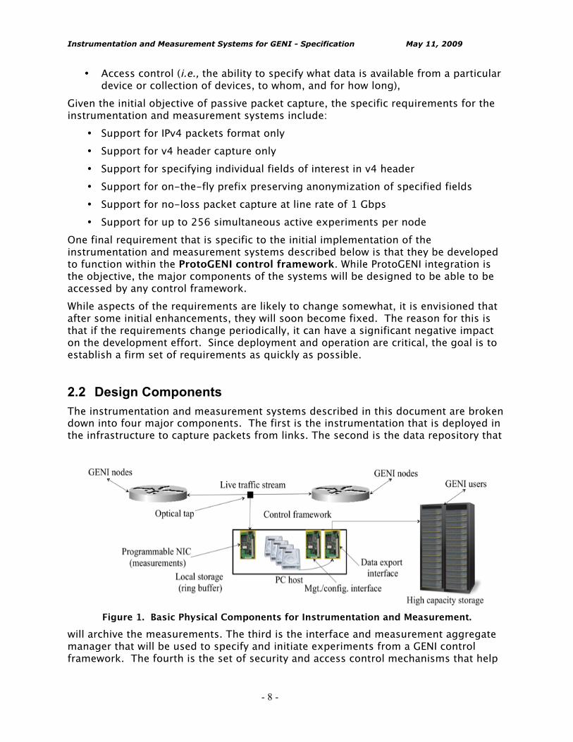
2.2 Design Components The instrumentation and measurement systems described in this document are broken down into four major components. The first is the instrumentation that is deployed in the infrastructure to capture packets from links. The second is the data repository that
Figure 1. Basic Physical Components for Instrumentation and Measurement.
will archive the measurements. The third is the interface and measurement aggregate manager that will be used to specify and initiate experiments from a GENI control framework. The fourth is the set of security and access control mechanisms that help
Instrumentation and Measurement Systems for GENI - Specification May 11, 2009
- 9 -
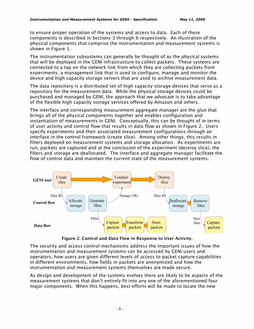
to ensure proper operation of the systems and access to data. Each of these components is described in Sections 3 through 6 respectively. An illustration of the physical components that comprise the instrumentation and measurement systems is shown in Figure 1. The instrumentation subsystems can generally be thought of as the physical systems that will be deployed in the GENI infrastructure to collect packets. These systems are connected to a tap on the network link from which they are collecting packets from experiments; a management link that is used to configure, manage and monitor the device and high capacity storage servers that are used to archive measurement data. The data repository is a distributed set of high capacity storage devices that serve as a repository for the measurement data. While the physical storage devices could be purchased and managed by GENI, the approach that we advocate is to take advantage of the flexible high capacity storage services offered by Amazon and others. The interface and corresponding measurement aggregate manager are the glue that brings all of the physical components together and enables configuration and instantiation of measurements in GENI. Conceptually, this can be thought of in terms of user activity and control flow that results in data flow as shown in Figure 2. Users specify experiments and their associated measurement configurations through an interface in the control framework (create slice). Among other things, this results in filters deployed on measurement systems and storage allocation. As experiments are run, packets are captured and at the conclusion of the experiment (destroy slice), the filters and storage are deallocated. The interface and aggregate manager facilitate the flow of control data and maintain the current state of the measurement systems.
Figure 2. Control and Data Flow in Response to User Activity.
The security and access control mechanisms address the important issues of how the instrumentation and measurement systems can be accessed by GENI users and operators, how users are given different levels of access to packet capture capabilities in different environments, how fields in packets are anonymized and how the instrumentation and measurement systems themselves are made secure. As design and development of the systems evolves there are likely to be aspects of the measurement systems that don’t entirely fit into any one of the aforementioned four major components. When this happens, best efforts will be made to locate the new
Instrumentation and Measurement Systems for GENI - Specification May 11, 2009
- 10 -
component or capability in the most appropriate component, but in and of itself, placement in this document is of less importance.
2.3 Design Exclusions This document describes requirements and specifications for measurement systems designed to capture packets on GENI network links. As stated above, the document does not include any descriptions of capabilities to monitor activity on end hosts or on network devices deployed in GENI. The document also excludes descriptions of measurements of activity below layer 3 and not specifically IPv4. It also excludes descriptions of any specific active probe-based measurement capability (which should be considered something specific to end host although measurements of probe packets would certainly be possible). The GDD-06-012 document specifically describes the need for data visualization and analysis tools that enable consistent evaluation of measurement data across experiments. While this capability is certainly important, developing these kinds of tools is beyond the scope of the current project.
2.4 Development Process There is a clear requirement for fully functional instrumentation and measurement capability with limited in-GENI deployment by 2011. The scope of the deployment depends on available funds to purchase and deploy measurement and data archiving systems. There is also a requirement for an intermediate deployment of instrumentation and measurement capability in the Wisconsin Advanced Internet Laboratory (WAIL) by October 2009. The objective of the WAIL deployment is to gain experience on how the systems work, where they require enhancement and as an important milestone for early prototype capability. Given these significant targets, the development process will proceed as follows. An initial planning and organization phase in which the initial version of this document was created. On-going updates will be done in parallel the initiation of development of the basic design components (instrumentation/archive/interfaces/access control) with the goal of an initial prototype deployed in WAIL by early summer. This will then trigger a “deploy-learn-update” cycle that will continue over the course of the project until 2011. Throughout this process users and other experts will be solicited for input and related ProtoGENI projects will be kept informed about the progress of our work. To facilitate design and development of the instrumentation and measurement systems, the team will continue it’s weekly teleconferences, will communicate via email and through a project Wiki and will meet face to face periodically. Standard component in systems development processes are source version control management (e.g., Subversion) and bug tracking (e.g., Flyspray) systems. Developers will adopt the use of these systems in this project. Not only do they help to ensure that systems are developed in a consistent and documented fashion, but they also help with transitions between developers, which is to be expected during this course of this project. Similarly careful documentation and code reviews are important tools to ensure high quality code. Both will be important to this project.
Instrumentation and Measurement Systems for GENI - Specification May 11, 2009
- 11 -
Finally, a key component in our development process is thorough test and evaluation of the instrumentation and measurement systems. We adopt the idea of test driven development in which tests for the various components are designed and specified before their development. This approach has been shown to be effective in the development of a wide variety of commercial hardware and software systems. This approach forces developers to consider how their subsystem is supposed to behave from a functional and performance perspective before they begin to code. The test and evaluation framework for the GENI instrumentation and measurement systems is describe in Section 7.
Instrumentation and Measurement Systems for GENI - Specification May 11, 2009
- 12 -
3 Instrumentation In this section we describe the functional requirements and design of the instrumentation component. We also discuss physical deployment issues, and relationships between the instrumentation component, the interface component and data repository component. The instrumentation subsystem consists of a set of link and time sensors that are deployed in the GENI testbed infrastructure. These sensors are designed to provide basic packet capture capability to experiments running in the infrastructure. Packet capture initiation, termination, and status query are accomplished through interfaces to the GIMS, as described in Section 5. Captured packets are made available to experimenters through the data repository, as described in Section 4. In the present design we assume a wireline infrastructure (e.g., optical fiber). We further assume an Ethernet VLAN-based environment. As far as possible, any related dependencies are minimized and shielded through abstraction layers. We further assume an Ethernet VLAN-based environment to distinguish traffic provenance.
3.1 Subsystem Components There are two basic components that comprise the instrumentation subsystem: link sensors and time sensors. In this subsection we describe these components. Note that this description closely follows the GIMS specification in [GDD-06-12]. 3.1.1 Link Sensors Link sensors are deployed on all (or some portion) of the physical links in the infrastructure and enable frames transmitted on those links to be extracted. While in general it will be preferable long-term to avoid making any assumption about the underlying nature of the binary signals on a link, in this design we assume an Ethernet VLAN environment. Thus, all captured frames are IEEE 802.1Q Ethernet VLAN packets. Signals on a given link may either be photons or electrical impulses. In the case of photonic signals, the standard method for tapping a link is to install a passive 50/50 Y-splitter (e.g., [SPLIT]) that makes a duplicate of the light signal on the primary path available on a secondary path that will terminate at a packet processing device. In the case of signals on copper/electrical links, there are several standard methods for instrumentation that are not unlike those for fiber/optical links. The first is to use basic port mirroring capability available on many types of network nodes. This approach requires the network node to copy all signals on a given port to a monitoring port. For high-speed links, resource demands in this configuration can detrimentally alter the performance or behavior of the network node. A second method is to physically break the link between two nodes and to install a mirroring device such as a Test Access Port [TAPS]. Note that in this design we do not consider link sensors for wireless environments.
Instrumentation and Measurement Systems for GENI - Specification May 11, 2009
- 13 -
3.1.2 Time sensors Time sensors provide a high fidelity, synchronized time source for applying timestamps to captured packets. A time sensor may be realized as (1) a Network Time Protocol (NTP) feed, which offers the ability to generate timestamps that are synchronized on the order of milliseconds, (2) an IEEE Precise Time Protocol (IEEE1588) time source, which can provide microsecond-level timestamp accuracy, (3) a high-fidelity time source such as a GPS receiver, which can enable timestamp accuracy on the order of nanoseconds, or (4) a software-clock solution such as [PV02], which leverages NTP yet provides are more stable and accurate source of timestamps. 3.1.3 Packet processing device Ethernet 802.1Q frames that have been diverted using a link sensor, as described above, are received by a packet processing device. This device may be a dedicated, specialized hardware component, e.g., [DAG], [PEXP], [BIVIO], or may be realized in software alone, e.g., similar to tcpdump [TDMP]. Capabilities and limitations of the device are made know to GENI experimenters through the external control interface, and through metadata that is associated with any collected data. In most cases, the packet processing device will be tightly connected to the time sensor, in that received packets must be timestamped as soon after reception as possible. For example, the device may support a Pulse-per-second feed and have a high-frequency oscillator in order to interpolate between PPS signals (as is done on Endace DAG systems [DAG]). 3.1.4 Instrumentation host The packet processing device is attached to or directly housed in (e.g., in a PCI-e slot) an instrumentation host. This host may realized as a commodity x86-based rackmount workstation that provides general computation, memory, and limited permanent storage resources. In general, the link sensor is co-located with the instrumentation host but not physically contained in it. Between the instrumentation host and the packet processing device, higher-level transformation functionalities are supported, e.g., filtering, aggregation, sampling, as described below. Specifically where (in the packet processing device or in the instrumentation host) such higher-level functionalities are implemented is generally irrelevant for the purposes of this document. Depending on capabilities of a given packet processing device, some functions may be “pushed down” for performance gains. Other functions may not be supported on a given packet processing device and must be implemented in software on the instrumentation host. Depending on the specific time sensor used, the time sensor may or may not be housed directly in the instrumentation host. For example., in the case of GPS, a physical PCI card may be installed in the instrumentation host. Alternatively, a PPS signal (derived from a co-located GPS-synchronized source) may be available, obviating the need to install a card in the instrumentation host. The instrumentation host has network connectivity to support external control and to make measurements available to experimenters via the repository subsystem. Refer to
Instrumentation and Measurement Systems for GENI - Specification May 11, 2009
- 14 -
the relevant external interface and repository subsystem sections for details on how these physical network connectivities are realized.
3.2 Functional Requirements The instrumentation subsystem is responsible for providing high-fidelity, synchronized, slice-aware passive packet capture to GENI experiment slices. 3.2.1 Basic functionality Requirements for basic functionality of the instrumentation subsystem are as follows:
• High-performance packet capture devices connected to link sensors must provide per-slice packet capture at line rate speeds, with minimal loss of captured packets.
• High-resolution timestamps must be applied to each captured packet. Time sensors at each deployed GIMS instance must be synchronized to within ε seconds of a master reference clock, such that ε is sufficiently small in order to enable direct comparison of timestamps obtained from any two deployed GIMS instances.
• Measurement quality metadata must be associated with a given captured data stream for a given slice. This metadata may be stored inline (among the captured packet data) or in a separate context. This metadata must include: (1) any time periods during which packets were dropped due to the packet capture device’s (or link sensor’s) inability to keep up with the received packet stream, (2) time sensor synchronization quality measures at the start of packet capture, (3) timestamp resolution accuracy (e.g., 1 ns, 1 ms), and (4) any time periods during packet capture in which time sensor synchronization exceeds a given threshold (i.e., periods in which the time sensor was not well-synchronized).
• Transformations must be applied to packets in a way that does not disrupt or impede packet capture at line rate. Functionalities of various transformations are described below.
• Instrumentation subsystem must allow arbitrary starting and stopping of per-slice packet capture without disruption or performance impedance for any slice in progress. Thus, the system must support addition or deletion of per-slice capture and transformation on-the-fly.
• Packet capture for operations and management purposes must be supported. Such functionality must allow capturing of all packets for all slices, with optional transformations (with functionality as described below) applied to the aggregate packet stream. Note that this requirement implies that some packets may need to be (in effect) duplicated if per-slice capture and O&M aggregate capture are simultaneously in progress.
• Depending on policy and capabilities (e.g., throughput) of the packet capture device, packet headers as well as payloads may be collected.
In addition to basic packet capture, the instrumentation subsystem may perform optional transformations on the packets for a given slice, as configured through the external control interface. Transformations include filtering, sampling, anonymization, and aggregation. These transformations may be applied globally, to all packets
Instrumentation and Measurement Systems for GENI - Specification May 11, 2009
- 15 -
captured at a given physical instantiation of the GIMS, or per-slice. Global transformations may only be directly specified through GENI management and operations, not by a given slice. 3.2.2 Transformation functionality In addition to basic packet capture, the GIMS supports a set of transformation functionalities. In this subsection, we describe the functionalities and scope of these transformations. These transformations may be applied globally (to all 802.1Q frames received at the packet processing device), or per-slice. Each transformation is optional and is applied in the order in which they are described below. That is, received frames are first sampled, then filtered, then anonymized, then aggregated.
3.2.2.1 Sampling First, a sampling function may be applied to received frames. The sampling function selects packets from the arriving stream of packets to be retained and passed to further transformation elements. Packets that are not selected are dropped. There are many different possible selection functions, e.g., see [PSAMP], [TRAJ]. At minimum, the sampling selection function to be supported in this design is uniform probabilistic sampling. That is, a packet is selected independently with uniform probability p.
3.2.2.2 Filtering Following sampling, a filtering step may optionally be applied to received frames. Upon receipt of a packet, it may be subjected to a filter expression. This expression may be thought of as similar to a Berkeley Packet Filter or libpcap expression, such as one specified when using tcpdump [TDMP]. If a received packet matches the expression, the packet is kept, otherwise the packet is dropped. Minimum filter expression functionality to be initially supported in the GIMS are:
• Host or network address: IP destination or source addresses for a given host or network may be specified in order to filter received packets.
• Protocol: The IP protocol number may be specified in order to filter received packets. • Port: For TCP or UDP packets, source and/or destination ports may be specified. • Raw bitwise comparison: for initial support of non-IP packets, simple bitwise
comparisons may be specified. A bitstring and an offset must be specified for this type of filter. If the given bitstring matches the bitstring at the given offset in a received frame, the packet is retained. Otherwise, it is dropped.
For IP-specific filters, both IPv4 and IPv6 should be supported.
Instrumentation and Measurement Systems for GENI - Specification May 11, 2009
- 16 -
3.2.2.3 Anonymization Following filtering, an optional anonymization transformation may be applied to received frames. Data anonymization is probably the most difficult functionality to fully specify in the initial stages of GIMS development, as local (i.e., the site at which the instrumentation host and associated systems are installed) policy plays a critical role. At minimum, address anonymization must be supported. Furthermore, metadata related to anonymization must be associated with a data stream (assuming an anonymization transformation is applied). Pang et al. provide an excellent analysis of various issues related to anonymization and associated metadata; their tcpmkpub tool described in [PAPL06] will be used to guide further definition and design of this transformation element. Note that for experiments in which measurements are collected at multiple instrumentation systems, any cryptographic keys used in the anonymization process must be identical in order to enable consistent analysis across the collected data.
3.2.2.4 Aggregation Finally, received frames may optionally be aggregated. By aggregation, we mean that the information contained in individual packets may be combined in different ways to produce different, yet related data. Some detailed information from individual packets is lost through the aggregation process, the result of which is generally a more compact, abstracted view of the captured traffic. Two common examples of data aggregate include (1) combining individual packets into flow records, where a flow may be defined by all packets sharing common source and destination addresses, protocol number, and ports, and (2) counts of packets that match certain criteria, i.e., SNMP-like capability. For examples of existing system providing such functionality, see Cisco’s Netflow [NFLOW], CAIDA’s CoralReef toolset [CORAL], and N. Brownlee’s NeTraMet tool [NMET]. The aggregation component must support, at minimum, flow record construction and basic packet count aggregation. For packet count aggregation, packet matching expressions such as those available through NeTraMet or through the standard tcpdump tool should be supported.
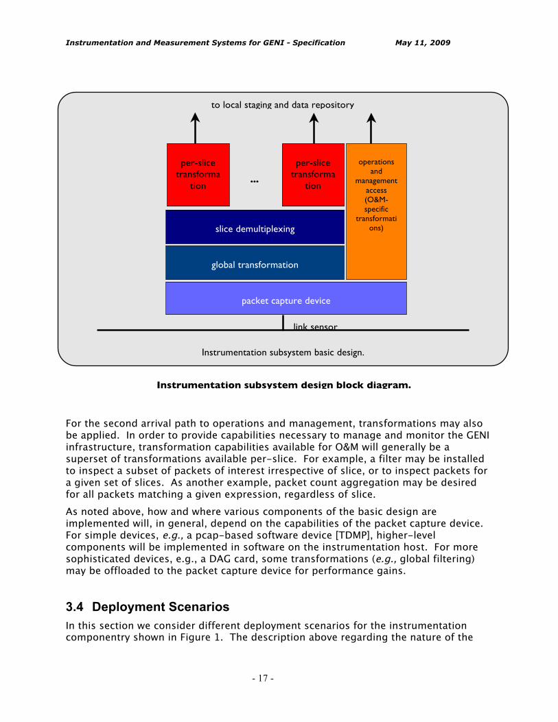
3.3 Subsystem basic design The interactions and data flow among the components described above lead to the basic design of the instrumentation subsystem depicted in the figure below. Incoming Ethernet frames are diverted through the link sensor and enter the packet capture device. Upon arrival packets may be delivered on a data path leading to experiment slices, to operations and management access, or both. In the first case, global transformations are applied to all arriving packets. Packets are then demultiplexed to different experiment slices based on Ethernet 802.1Q VLAN tags. Slice-specific transformations are then applied. Following this, packets are delivered to the local storage for staging prior to delivery to the data repository.
Instrumentation and Measurement Systems for GENI - Specification May 11, 2009
- 17 -
For the second arrival path to operations and management, transformations may also be applied. In order to provide capabilities necessary to manage and monitor the GENI infrastructure, transformation capabilities available for O&M will generally be a superset of transformations available per-slice. For example, a filter may be installed to inspect a subset of packets of interest irrespective of slice, or to inspect packets for a given set of slices. As another example, packet count aggregation may be desired for all packets matching a given expression, regardless of slice. As noted above, how and where various components of the basic design are implemented will, in general, depend on the capabilities of the packet capture device. For simple devices, e.g., a pcap-based software device [TDMP], higher-level components will be implemented in software on the instrumentation host. For more sophisticated devices, e.g., a DAG card, some transformations (e.g., global filtering) may be offloaded to the packet capture device for performance gains.
3.4 Deployment Scenarios In this section we consider different deployment scenarios for the instrumentation componentry shown in Figure 1. The description above regarding the nature of the
packet capture device
global transformation
slice demultiplexing
per-slice transforma
tion
operations and
management access (O&M-specific
transformations)
to local staging and data repository
link sensor
per-slice transforma
tion
...
Instrumentation subsystem basic design.
Instrumentation subsystem design block diagram.
Instrumentation and Measurement Systems for GENI - Specification May 11, 2009
- 18 -
link sensor component implies that the instrumentation host and associated hardware is co-located with GENI routers. However, this may be considered a special case. Consider, for example, the case of two router nodes connected with a single span Gigabit link (no intervening routers or switches). From the view of a control framework, this setting may be described by three separate components: node A, node B, and the Gigabit link. If packet capture from the Gigabit link is desired, there are a few possible options:
• Capture packets on node A, e.g., by using port-mirroring • Capture packets on node B, e.g., by using port mirroring • Capture packets using a passive tap (link sensor) installed adjacent to node A • Capture packets using a passive tap (link sensor) installed adjacent to node B • Deploy personnel to manually insert an intervening transparent node between nodes
A and B • Using unspecified mechanisms, automatically insert an intervening transparent node
between nodes A and B. If a more complex multihop layer 1 or layer 2 backbone is considered, additional options are possible:
• Activate a preexisting passive tap on a link, • Automatically insert an intervening transparent node by means of a lambda switch, • Divert traffic between two nodes of an experiment such that traffic passes through an
existing (and available) measurement platform. In general, the instrumentation subsystem design is agnostic to the specific deployment scenario. However, the basic operating assumption of the present design is that a preexisting passive tap will be activated in order to capture desired packet traffic. In this case, measurement capability may be considered as a special feature of a given link.
3.5 Interfaces to other subsystems The instrumentation subsystem is but one component of the measurement and instrumentation platform described in this document. In this section, we describe the interactions between the instrumentation subsystem and two other key subsystems: the control interface and the repository. 3.5.1 Control interface interaction The instrumentation subsystem will export an API that enables the various components of Figure 1 to be configured, reconfigured, and queried. While the specific nature of this API is yet to be determined (e.g., in terms of how the API is realized in software, function names, arguments, semantics, etc.), the general capabilities through this API will be as follows:
• Add or delete a global transformation element.
Instrumentation and Measurement Systems for GENI - Specification May 11, 2009
- 19 -
• Add an experiment slice. A new slice element will be added; information on identifying the slice must be given (i.e., VLAN tag).
• Remove an experiment slice. • Add or delete a per-slice transformation element. • Initiate slice measurement. Given an existing slice and any transformation elements,
enable measurement for the slice, and enable collected data to be passed to repository subsystem.
• Terminate slice measurement. • Add or delete a O&M transformation element. • Initiate O&M measurement. • Terminate O&M measurement. 3.5.2 Repository subsystem interaction Once packet data has been suitably processed by the instrumentation subsystem, it will be made available to the repository subsystem for analysis and archival purposes. Collected and transformed data will be delivered to a local storage service (“scratch space”), at which point the repository subsystem will be invoked to transport the data to its permanent storage location. The mechanisms through which data is delivered to the local storage service are specified by the data repository service API Note that the data delivered to the local storage service may be the full data set for a given experiment slice (or O&M) (i.e., all data generated between initiation and termination of measurement), or may be delivered in discrete chunks. Different considerations must be made in this regard: local storage is likely to be somewhat limited, bandwidth for writing to local storage is likely to be higher than for writing to a remote repository, no one experiment should be able to consume local storage to the detriment of other experiment slices or O&M. The key implication for the instrumentation subsystem is that it must provide a best-effort service for storing experiment data and provide appropriate alerts to experiment slices or to O&M if local storage is insufficient. In extreme cases, the instrumentation subsystem may need to either overwrite data previously saved in local storage or to cease storing data on behalf of an experiment slice.
Instrumentation and Measurement Systems for GENI - Specification May 11, 2009
- 20 -
4 Data Archive The third element of the GIMS is the archival repository into which measurements from the collection systems are stored and then made available for analysis. This section describes the initial storage system for GIMS. Portions of this description are based on the GIMS specification in [GDD-06-12]. An example of an existing repository similar to what is envisioned for GENI is CRAWDAD, which is used for warehousing and sharing wireless measurements [CRAWDAD]. The objectives for the archive are, (1) to provide a secure, reliable repository to GENI users for measurements taken in their experiments, and (2) to provide a standard interface for data extraction so that users can analyze their data at their own sites. The archive will have two primary components: the repository itself, and a data catalog that indexes the data in the repository. The archive itself will be located in several GENI sites as well as third-party storage. This enables the archive to be resilient to site-specific failures and will spread the network load for both sensor-to-archive transfers and archive-to-user transfers. 4.1 Repository The repository consists of a set of interfaces for storing and retrieving datasets, and a collection of physical storage. In keeping with the spiral design philosophy of GENI and the budget limitations imposed on the GIMS initial version, actual storage capacity will be provided through the use of a third-party “cloud” storage vendor, such as Amazon’s S3 service. Amazon S3 provides offload of the physical storage via its collection of storage farms located in the US and Europe. Use of a cloud storage solution addresses a number of issues with respect to the GIMS repository. First, it frees the GENI system from the management issues of keeping extensive, large-scale storage systems running and configured. Second, it allows the ultimate decision of how and where to provide storage in the GENI system to be deferred, in keeping with the spiral design philosophy. Third, it addresses the issue of storage space management by charging the costs of storage use to the system users – it aligns incentives so that system users do not consume storage space irresponsibly. Fourth, it provides a set of well-defined interfaces for the insertion and removal of datasets by users (e.g., SOAP and HTTP). And finally, it responds to the constraints of the initial GIMS budget by offloading the expense of storage provisioning to the system users. A concern in using third-party storage is the safety of measurement data. This is ensured through the use of cryptographic keys allowing access to data only to authorized users. The interfaces for storing and retrieving datasets will make use of these cryptographic keys. Users who desire to collect measurement data via GIMS will open an Amazon S3 account, which will generate and supply them with the appropriate keys. Users will then supply those keys to the GIMS before the start of data collection. GIMS will place the collected data into S3 where the data can be accessed by users in a secure fashion.
Instrumentation and Measurement Systems for GENI - Specification May 11, 2009
- 21 -
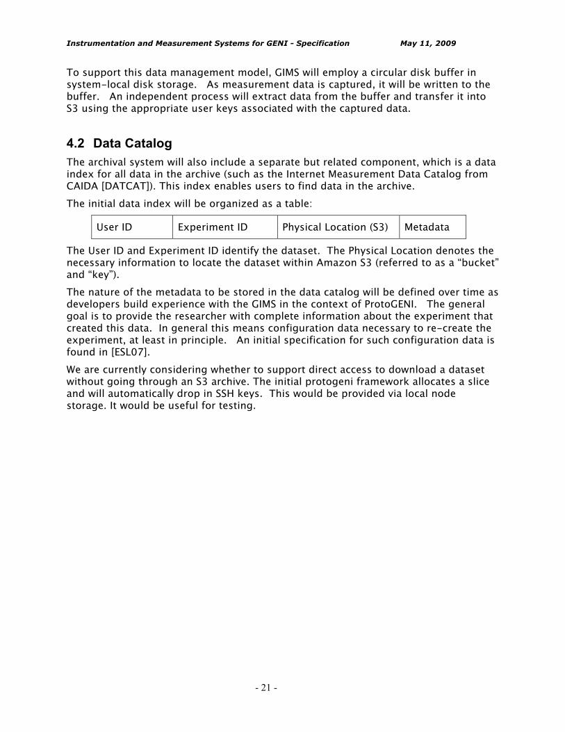
To support this data management model, GIMS will employ a circular disk buffer in system-local disk storage. As measurement data is captured, it will be written to the buffer. An independent process will extract data from the buffer and transfer it into S3 using the appropriate user keys associated with the captured data. 4.2 Data Catalog The archival system will also include a separate but related component, which is a data index for all data in the archive (such as the Internet Measurement Data Catalog from CAIDA [DATCAT]). This index enables users to find data in the archive. The initial data index will be organized as a table:
User ID Experiment ID Physical Location (S3) Metadata
The User ID and Experiment ID identify the dataset. The Physical Location denotes the necessary information to locate the dataset within Amazon S3 (referred to as a “bucket” and “key”). The nature of the metadata to be stored in the data catalog will be defined over time as developers build experience with the GIMS in the context of ProtoGENI. The general goal is to provide the researcher with complete information about the experiment that created this data. In general this means configuration data necessary to re-create the experiment, at least in principle. An initial specification for such configuration data is found in [ESL07]. We are currently considering whether to support direct access to download a dataset without going through an S3 archive. The initial protogeni framework allocates a slice and will automatically drop in SSH keys. This would be provided via local node storage. It would be useful for testing.

Instrumentation and Measurement Systems for GENI - Specification May 11, 2009
- 22 -
5 Interfaces There are several interfaces that are required to facilitate measurement in GENI. They include:
• The interface presented to the user by the control framework that enables configuration of the measurement components in an experiment,
• The interface between the control framework and the packet capture instruments deployed in the GENI infrastructure,
• The interface between the control framework and the data archival systems • (Possibly) and interface between the measurement systems and a GENI
management framework, which is yet to be specified. The primary requirements for these interfaces are ease of use, efficiency, extensibility (including possibly across control frameworks), scalability and to support access control. The need to simplify the many interfaces has led to the incorporation of a GIMS aggregate manager that sits in between the control framework and the instrumentation plane. This is shown in Figure 3.
Figure 3. Interfaces.
5.1 Interface components 1) Extension of the control framework interface to enable users to specify measurements 2) The instrumentation and measurement aggregate manager. In accordance with the Facility Design document (GDD-07-44) this section introduces the set of interfaces by which principals manipulate components, slices, and
Instrumentation and Measurement Systems for GENI - Specification May 11, 2009
- 23 -
aggregates of the GIMS system. The discussion is purposely high-level. A companion set of XSD and WSDL specifications give precise definitions of the GIMS interfaces. -Measurement Rspec A set of measurement resource specifications is used to communicate between users and components the available and requested measurement operations. Since a measurement ability can exist within so many components of the the GENI infrastructure we must define a set of specifications that can easily describe the distributed nature and varied capabilities of GENI ecosystem. -- Location We must first make the user aware of where measurement capabilities exist. In the simplest case, a component in the GENI infrastructure (e.g., PC or router) might have a native capability. The node would advertise this capability just like a CPU or disk. A second example would be a network span optically tapped to a dedicated capture appliance. The resource specifications that describes the connections between the two endpoint components on the link must be extended to specify the link is tapped by our GIMS component. A advanced scenario would be a colo facility interconnected by a optical switch. A measurement appliance or multiple appliances may be able to be switched between some number of links, most likely requiring us to integrate with some sort of aggregate manager. -- Capability In addition to where a measurement point exists, we must define the capabilities. A dedicated packet capture appliance might have the follow capabilities: 1. Capture throughput - might be less then raw line speed 2. Filtering - Ethernet, IP, Payload 3. Sampling - User definable? 4. Local storage 5. Available output methods - Archive, stream, relay to synthesis Most commercial IP routers have a flow export capability. In this case the flow export is a measurement capability of the router, but we need to force the data stream to a synthesis component to possibly filter the flows. This part of the Rspec will be continually extended to support additional equipment and measurement tasks. -- Tickets Once a user is aware of the available resources, they can request a ticket, and later redeem the ticket to create a sliver on the GIMS component.
Instrumentation and Measurement Systems for GENI - Specification May 11, 2009
- 24 -
-Component Operations The GIMS measurement systems consist of a number of GENI components, which export the standard component manager (CM) interfaces discussed in sections 2.2.4 Component Operations of the GENI Facility design document GDD-07-44. These standard interfaces should be utilized for measurement operations, defining additional interface calls only where absolutely required. --Obtaining Right to Component Resources See Section 2.2.4 of GDD-07-44 GIMS components follow the standard operations. --Controlling a Slice See Section 2.2.4 of GDD-07-44 GIMS components follow the standard operations, in addition an additional call maybe defined to return status or debugging messages from a slice. Alternatively the debug or status channel may be requested when creating the sliver. --Slice Information See Section 2.2.4 of GDD-07-44. GIMS components follow the standard operations. --Aggregate Operations It's possible multiple GIMS components might work in aggregate. Examples might be a collection of wireless monitors geographically distributed or perhaps a collection of sensors each monitoring a different portion of the RF spectrum. Exact details of aggregate operations would be specific to the implementors and technologies being aggregated.
5.2 Prototype UI The existing ProtoGENI user interface (UI) is a Flash-based graphical interface that, in its unmodified incarnation, handles user authentication/authorization as well as the allocation of experimental resources (slices) within the GENI framework. We intend to extend the existing UI to allow it to handle configuration and control of the GIMS packet capture appliance(s). The modified UI will also permit the user to specify various experimental setup parameters and start/stop the packet capture device(s) during the experiment. It will also (potentially) provide feedback from the various GIMS components during and after the GENI experiment.
Instrumentation and Measurement Systems for GENI - Specification May 11, 2009
- 25 -
5.2.1 Components
5.2.1.1 ThemodifiedProtoGENIFlashUI
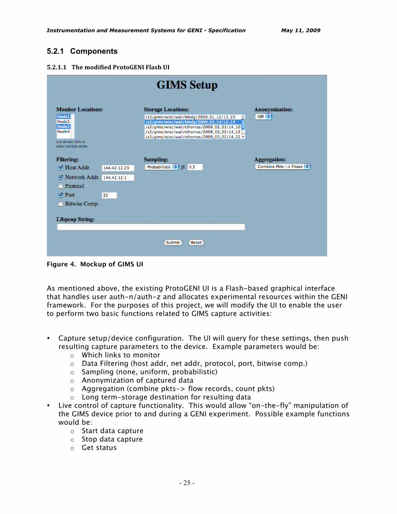
Figure 4. Mockup of GIMS UI As mentioned above, the existing ProtoGENI UI is a Flash-based graphical interface that handles user auth-n/auth-z and allocates experimental resources within the GENI framework. For the purposes of this project, we will modify the UI to enable the user to perform two basic functions related to GIMS capture activities: • Capture setup/device configuration. The UI will query for these settings, then push
resulting capture parameters to the device. Example parameters would be: o Which links to monitor o Data Filtering (host addr, net addr, protocol, port, bitwise comp.) o Sampling (none, uniform, probabilistic) o Anonymization of captured data o Aggregation (combine pkts-> flow records, count pkts) o Long term-storage destination for resulting data
• Live control of capture functionality. This would allow “on-the-fly” manipulation of the GIMS device prior to and during a GENI experiment. Possible example functions would be:
o Start data capture o Stop data capture o Get status
Instrumentation and Measurement Systems for GENI - Specification May 11, 2009
- 26 -
o Generate report(s) (number of pkts captured, observed line rates, error rates, dropped pkts, etc)
The UI will gather information from the user and push it to the GIMS Backend for processing. From there the commands will be sent to the GIMS devices themselves.
5.2.1.2 TheGIMSBackend
The GIMS Backend is both an XML/RPC server which accepts incoming messages on a standard HTTP connection, and also a socket-based UDP application. The role of the GIMS Backend is to sit in the measurement space and serve as a liaison between the ProtoGENI UI and the GIMS capture devices themselves. The application will leverage knowledge of the local networking environment in this role, resulting in a GIMS control UI that can be abstracted from many local details that would not be applicable to the GENI framework as a whole. The GIMS Backend functions as a standard XML/RPC server, accepting connections via HTTP, and receiving well-formatted XML/RPC instructions from the ProtoGENI UI. These instructions will be of two basic types: GIMS control messages and GIMS configuration messages. These messages will be described in more detail later. The XML/RPC commands received from the UI will be massaged as needed, then using local networking knowledge, the GIMS Backend will forward the command to the GIMS device that is the intended recipient. The Backend will open a UDP connection to the target GIMS capture device and forward it as required. Any responses generated by the GIMS device, either in response to user commands or spontaneously in the course of the experiment (e.g. error or status messages), will be encoded by the GIMS Backend into XML/RPC replies and forwarded back to the UI as necessary thus providing the user with necessary feedback.
5.2.1.3 Theaggregatemanager(AM)
The line of responsibility between the AM and the GIMS Backend is not totally clear at this point. As a first step, the AM could function as a directory-style resource that would contain reachability and capability information about GIMS devices, the GIMS backend, and long-term storage. Generally-speaking the AM would function to coordinate and facilitate the interplay between the other components in the GIMS portion of a GENI experiment.

Instrumentation and Measurement Systems for GENI - Specification May 11, 2009
- 27 -
The mechanism by which the AM will obtain this information has not yet been determined. Availability and capability info may be pushed to the AM by the devices in question, or the AM may poll the network looking to discover such resources when they become available. It seems likely that some kind of resource registration process may be required in either case to make it easier for the AM to obtain information about the resources it will be managing.
5.2.1.4 TheGIMScapturedevice(s)
The GIMS capture device is initially envisioned as a dedicated high-speed line-rate DAG network monitoring packet capture card... blah, blah, blah. (Mike - details?)
5.2.1.5 Longtermdatastorage
As has been detailed elsewhere, long-term storage of captured traffic data is envisioned to be a pay-to-play facility analogous to Amazon’s S3 storage service. 5.2.2 Actions and Interactions
5.2.2.1 InteractionsbetweentheProtoGENIUIandtheAggregateManager
Initially it is envisioned that the AM would be contacted by the GIMS UI for the following information: • List of GIMS devices • List of long-term storage repositories • For each GIMS device:
o URL of the GIMS Backend for the device o Links/Nodes available to be monitored by the device o Filtering options, aggregation options, and other capabilities of the device
This information would be used to pre-populate the selection components in the UI presented to the user.
5.2.2.2 InteractionsbetweentheProtoGENIUIandtheGIMSBackend
After having collected user input regarding collection setup and configuration, the UI will encapsulate this information in XML/RPC code and call the URL for the GIMS

Instrumentation and Measurement Systems for GENI - Specification May 11, 2009
- 28 -
Backend. The XML/RPC code will be forwarded to the GIMS backend for further processing as described below. A similar set of steps will be used to pass live capture control commands (e.g. ‘start capture’, ‘stop capture’) to the GIMS devices in use during a GENI experiment.
5.2.2.3 InteractionsbetweentheGIMSDaemonandtheGIMSdevice(s)
The Backend will massage this data as needed (depending on the local networking environment), open a UDP port and pass the configuration data to the GIMS device in question. Responses from the device will be received, packaged in XML/RPC code and forwarded back to the UI to create user feedback. In this way the UI is decoupled from having to know too many specifics about where the GIMS devices live, how to talk with them, etc. Once the UI obtains a URL for the GIMS Backend from the Aggregate Manager, it can send simple commands to the Backend and the Backend will take care of configuring ports, massaging the messages as needed, and all other heavy lifting required to interface with the specific implementation of the GIMS device. This abstraction can allow the capture hardware, IP address, ports, and other specifics of the GIMS device to change over time or to vary from location to location without the UI being affected.
5.2.2.4 Transferofcaptureddatatolongtermdatastorage
Once filtered and processed data starts being saved to the local disk by the GIMS device, there will need to be a way to start off-loading this data to the specified long-term storage. One possible mechanism to deal with this task is to create a dedicated “Sweeper Daemon” which would could be awakened with a call of (local_location, long_term_location, [COPY, MOVE]) where local_location would be the directory on the local GIMS machine where capture data was being stored and ‘long_term_location’ was the long term data storage facility where the data was going to reside permenantly. The daemon would subsequently begin the process of forwarding this data to long-term storage even while the experiment is being conducted. Depending on the user’s wishes, the data could either be a COPY operation to long-term storage (with a copy left on local storage) or a MOVE operation, cleaning off local storage as it goes. Details of this or other potential transfer mechanisms have not yet been firmed up.
Instrumentation and Measurement Systems for GENI - Specification May 11, 2009
- 29 -
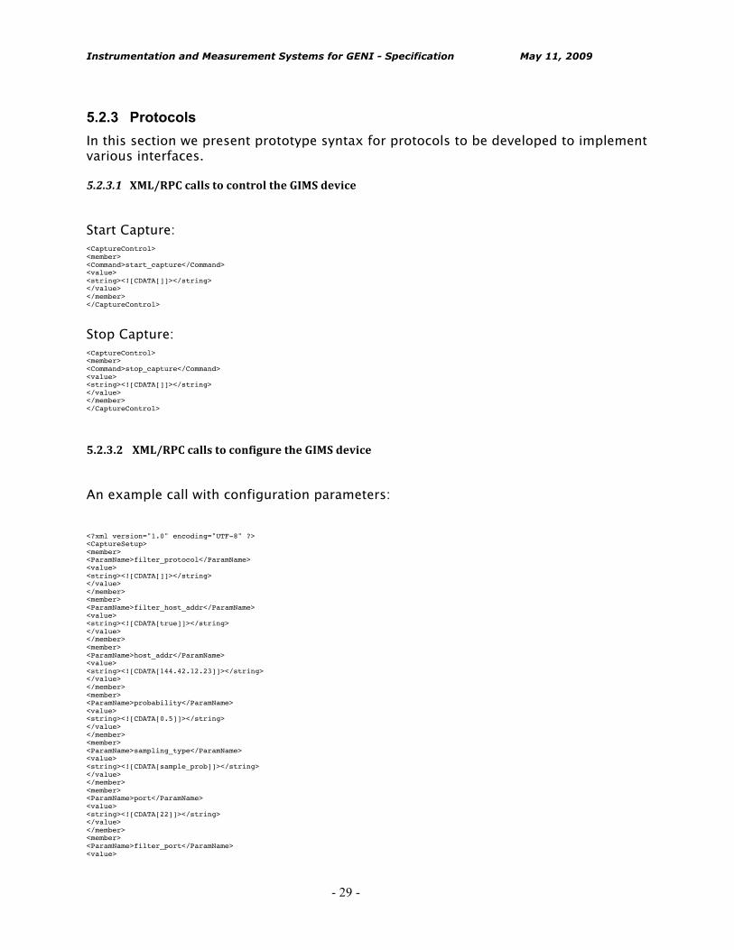
5.2.3 Protocols In this section we present prototype syntax for protocols to be developed to implement various interfaces.
5.2.3.1 XML/RPCcallstocontroltheGIMSdevice
Start Capture: <CaptureControl> <member> <Command>start_capture</Command> <value> <string><![CDATA[]]></string> </value> </member> </CaptureControl>
Stop Capture: <CaptureControl> <member> <Command>stop_capture</Command> <value> <string><![CDATA[]]></string> </value> </member> </CaptureControl>
5.2.3.2 XML/RPCcallstoconfiguretheGIMSdevice
An example call with configuration parameters: <?xml version="1.0" encoding="UTF-8" ?> <CaptureSetup> <member> <ParamName>filter_protocol</ParamName> <value> <string><![CDATA[]]></string> </value> </member> <member> <ParamName>filter_host_addr</ParamName> <value> <string><![CDATA[true]]></string> </value> </member> <member> <ParamName>host_addr</ParamName> <value> <string><![CDATA[144.42.12.23]]></string> </value> </member> <member> <ParamName>probability</ParamName> <value> <string><![CDATA[0.5]]></string> </value> </member> <member> <ParamName>sampling_type</ParamName> <value> <string><![CDATA[sample_prob]]></string> </value> </member> <member> <ParamName>port</ParamName> <value> <string><![CDATA[22]]></string> </value> </member> <member> <ParamName>filter_port</ParamName> <value>

Instrumentation and Measurement Systems for GENI - Specification May 11, 2009
- 30 -
<string><![CDATA[true]]></string> </value> </member> <member> <ParamName>libpcap_string</ParamName> <value> <string><![CDATA[This could be a libpcap string.]]></string> </value> </member> <member> <ParamName>storage_location</ParamName> <value> <string><![CDATA[s3_gims_wisc_wail_blodg_exp2]]></string> </value> </member> <member> <ParamName>filter_net_addr</ParamName> <value> <string><![CDATA[true]]></string> </value> </member> <member> <ParamName>aggregation_type</ParamName> <value> <string><![CDATA[combine_pkts_flows]]></string> </value> </member> <member> <ParamName>anonymize</ParamName> <value> <string><![CDATA[on]]></string> </value> </member> <member> <ParamName>filter_bit_comp</ParamName> <value> <string><![CDATA[]]></string> </value> </member> <member> <ParamName>net_addr</ParamName> <value> <string><![CDATA[144.42.12.1]]></string> </value> </member> <member> <ParamName>monitor_location0</ParamName> <value> <string><![CDATA[Fa_10_0_2]]></string> </value> </member> </CaptureSetup>
Instrumentation and Measurement Systems for GENI - Specification May 11, 2009
- 31 -
6 Security and Access Control There are significant issues of security and privacy for GIMS. The most general requirements for security and privacy are:
1. Sensors, collection/synthesis and archival systems must only be accessible by authorized users,
2. Authorized users must only be allowed access to a specified proportion of a the resources on the measurement systems,
3. Different views of the same data will be required depending on the approved level of authorization.
4. All of the measurement systems themselves must be secured against attack, 5. No aspects of the data that is collected will compromise or violate the privacy of
individuals or organizations that source/sink the data. The mechanisms for addressing requirements #1 - #4 above are all to be determined. There is a constant tension between desired visibility into measurement data and privacy. However, the privacy requirement (item #5) is very serious since if violated, it could lead to legal action against GENI. Therefore, a set of policies and procedures for requesting and granting access to the entire range of measurements available in GENI will have to be established. In many cases, this will be straightforward. For example, access to CPU utilization on a particular node that is openly available for use by anyone will be immediately authorized. Alternately, access to full packet traces (including payloads) on a link that handles commodity traffic may be possible under any circumstances (HIPPA guidelines will apply). The mechanisms for addressing privacy issues are to be determined.

Instrumentation and Measurement Systems for GENI - Specification May 11, 2009
- 32 -
7 Evaluation and test Careful and comprehensive test and evaluation of the instrumentation and measurement systems will ensure that they behave and perform in a predictable fashion when deployed in the GENI infrastructure. We adopt a test-driven development strategy toward the goal of producing high quality systems in a timely fashion. Test-driven development calls for the design and specification of functional and performance tests prior to development of individual subsystems. The goal of the tests is to be as comprehensive and as realistic as possible in terms of the conditions under which the subsystems will be evaluated. This document considers the measurement systems in terms of four components: instrumentation, data repository, interface, and access control. Tests for each of these components are described below. The specific objective in this document is to establish a general test framework for each component and then to add required details on tests as the component design matures. Tests will be automated to the extent possible (e.g., using scripts) so that they can be repeated. Detailed documentation on the tests and scripts will not be included in this document but will be maintained on the instrumentation and measurement system wiki. All of the tests will be conducted in the Wisconsin Advanced Internet Lab using simple network topologies, standard traffic generation tools and high performance packet capture devices to ensure that the experiments can be monitored and the results confirmed. 7.1 Tests for the Instrumentation Component The functional and performance requirements of the instrumentation component call for a test suite that will assure that it can effectively communicate with the interface and data archive components and that it can satisfy the packet capture accuracy and experimental multiplexing requirements (256 simultaneous users) that will enable the system to be deployed on 1 Gbps links. Tests for the instrumentation component are as follows: 7.1.1 Functional Tests The instrumentation component must communicate with both the interface and the data archive components. Functional tests will be conducted to exercise the data communication protocols between instrumentation – interface and instrumentation – data archive. The framework for the functional tests is as follows:
• Transmit experimental configurations from interface to packet capture system (PCS); test to see that configurations are established and consistent on PCS
• Expire experimental configurations on PCS; test to see that experiments are removed from PCS
• Transmit PCS status to interface; test to see that PCS status has been received • Transmit credentials from PCS to data repository in order to establish data
download channel to repository; test to ensure that channel is open
Instrumentation and Measurement Systems for GENI - Specification May 11, 2009
- 33 -
• Close channel between PCS and data repository; test to see that channel is closed
7.1.2 Performance Tests The performance target for the instrumentation component is that it be able to gather packets with zero loss on 1 Gbps links and transmit the (possibly transformed or anonymized) data to the repository with zero packet loss. This implies a number of different capabilities for the PCS including packet capture, data filtering and transformation, temporary local storage and streaming to the repository. The framework for the performance tests is as follows:
• Transmit varied (sizes and header information) packet streams at increasing rates up to 1 Gbps on a link that is tapped by a PCS using different filter sets; test to see that all packets that should be captured were actually captured
• Conduct the same test as above but include a requirement to stream the captured packets to a remote repository; test to see that the target packets are in the repository
• Conduct the same test as above but include required data anonymization or transformation; test to see that the target packets are in the repository
7.2 Tests for the Data Repository Component The data repository has a requirement to communicate with the interface and instrumentation components. It must also be able to handle data feeds with no packet loss from perhaps hundreds of GENI packet capture instruments deployed throughout the infrastructure. Tests for the data repository component are as follows: 7.2.1 Functional Tests TBD 7.2.2 Performance Tests TBD
7.3 Tests for the Interface Component The interface component must communicate with the systems used to manage and configure experiments, with measurement instruments deployed in the GENI infrastructure and with the data repository. While scalability is less of a concern since the load on the interface systems is constrained to configuration and management traffic, the systems must nevertheless be able to scale to support a community on the order of thousands of simultaneous users. Tests for the interface component are as follows:
Instrumentation and Measurement Systems for GENI - Specification May 11, 2009
- 34 -
7.3.1 Functional Tests TBD 7.3.2 Performance Tests TBD 7.4 Tests for the Access Control Component The access control component is actually part of the instrumentation, data repository and interface components. Both its functional and performance requirements remain nascent. Tests for the access control component are as follows: 7.4.1 Functional Tests TBD 7.4.2 Performance Tests TBD
Instrumentation and Measurement Systems for GENI - Specification May 11, 2009
- 35 -
8 References [CORAL] CAIDA. CoralReef, http://www.caida.org/tools/measurement/coralreef/,
2009. [GDD-06-11] L. Peterson and J. Wroclawski (Eds), “Overview of the GENI Architecture”,
GENI Design Document 06-11, Facility Architecture Working Group, September, 2006.
[GDD-06-12] P. Barford (Ed.), “GENI Instrumentation and Measurement Systems (GIMS)”, GENI Design Document 06-12, Facility Architecture Working Group, December, 2006.
[GDD-06-15] S. Paul (Ed.), “Requirements for Wireless GENI Management and Control”, GENI Design Document 06-15, Wireless Working Group, September, 2006.
[BIVIO] Bivio, Deep packet inspection, Wire-speed network applicances. http://www.bivio.net/, 2009.
[CRAWDAD] CRAWDAD, A Community Resource for Archiving Wireless Data at Dartmouth, http://crawdad.cs.dartmouth.edu, 2009.
[DATCAT] CAIDA, The Internet Measurement Data Catalog, http://imdc.datcat.org, 2006.
[DAG] Endace, Network Monitoring Cards, http://www.endace.com/, 2009. [DAYTONA] AT&T Labs Research, The Daytona Data Management System,
http://www.research.att.com/daytona, 2009. [ESL07] Eide, Stoller, and Lepreau. An Experimentation Workbench for Replaying
Networking Research. Proceedings of NSDI 2007. [NFLOW] Cisco Systems, Netflow white paper,
http://www.cisco.com/web/go/netflow, 2009. [NMET] N. Brownlee and CAIDA. NeTraMet,
http://www.caida.org/tools/measurement/netramet/, 2009. [PAPL06] R. Pang, M. Allman, V. Paxson, and J. Lee. The devil and packet trace
anonymization. ACM SIGCOMM Computer Communications Review, January 2006.
[PEXP] PcapExpress. http://www.pcapexpress.com/, 2009. [PSAMP] T. Zseby, M. Molina, N. Duffield, S. Niccolini, and F. Raspall. Sampling
and filtering techniques for IP packet selection. Internet Draft draft-ietf-psamp-sample-tech-11.txt, July 2008.
[PV02] A. Pasztor and D. Veitch, PC Based Precision Timing without GPS. In Proceedings of ACM SIGMETRICS ’02, Marina del Rey, CA, June, 2002.
[RPKW03] T. Roscoe, L. Peterson, S. Karlin, and M. Wawrzoniak. A Simple Common Sensor Interface for PlanetLab. http://www.planet-lab.org/PDN, March, 2003.
[SPLIT] Cisco Systems, WDM Splitter Cable, http://www.cisco.com/, 2009. [TAPS] NetOptics, Network Test Access Port Devices,
http://www.netoptics.com/, 2009.

Instrumentation and Measurement Systems for GENI - Specification May 11, 2009
- 36 -
[TDMP] tcpdump, http://www.tcpdump.org/, 2009. [TRAJ] N. Duffield and M. Grossglauser. Trajectory sampling for direct traffic observation. IEEE/ACM Transactions on Networking, Volume 9, Number 3, June 2001.