Embed Size (px)
Citation preview

Requirements-Level Semantics and Model Checking of Object-Oriented Statecharts
Rik Eshuis, David N. Jansen and Roel WieringaRik Eshuis, David N. Jansen and Roel WieringaDepartment of Computer Science, University of Twente, Enschede, The Netherlands
In this paper we define a requirements-level execution
semantics for object-oriented statecharts and show how
properties of a system specified by these statecharts can
be model checked using tool support for model checkers.
Our execution semantics is requirements-level because ituses the perfect technology assumption, which abstracts
from limitations imposed by an implementation. State-
charts describe object life cycles. Our semantics
includes synchronous and asynchronous communication
between objects and creation and deletion of objects.
Our tool support presents a graphical front-end to model
checkers, making these tools usable to people who are
not specialists in model checking. The model-checkingapproach presented in this paper is embedded in an
informal but precise method for software requirements
and design. We discuss some of our experiences with
model checking.
Keywords: Execution semantics; Model checking;Statecharts
1. Introduction
Statecharts allow the specification of complex event-driven behaviours, containing parallelism, event broad-casting, state hierarchy, interrupts and non-determinism.They have been used in structured analysis since themid-1980s [1,2] and in object-oriented analysis since theearly 1990s [3]. They take a central place in the UML[4], where they can be used, among others, to specifyobject life cycles.
Statecharts are powerful notations, and they have
proven to be an attractive means to specify behaviour.
But this very expressive power brings with it a host of
semantic issues that can decrease our ability to under-
stand the behaviour specified by means of statecharts.
This is a result of the large number of syntactic
combinations that can be made in statecharts, which
forces us to make a lot of semantic choices.
The issue is compounded by the fact that different
users of statecharts may make these choices differently.
Several years ago, von der Beeck [5] listed over 20
variants of statechart semantics in structural analysis
approaches, which all make these choices differently. A
single statechart in structured analysis can thus have
more than 20 different semantics. The number of
semantics actually in use has increased with every new
object-oriented method that incorporates statecharts. The
UML has not resolved this multiplicity. Reports from the
standardisation effort suggest that the final UML
semantics of statecharts will be one of the most complex
imaginable [6]. Moreover, the UML semantics contains
many open ends, which have to be filled in before
statecharts can be used.
This paper takes a route opposite to the UML, which
is aimed at simplicity and precision. We define a
lightweight version of statecharts that contains the
essential constructs of parallelism, state hierarchy and
state reactions and extend this with object-oriented
constructs for inter-statechart communication and for
object creation and deletion. We then define a
Statemate-like execution semantics for this, which is
formalised by means of a labelled transition system
(LTS). We implemented this semantics in our graphical
editing tool TCM [7], which allows the analyst to create
and edit a collection of formal and informal system
specifications. For some of the behaviour descriptions,
Requirements Eng (2002) 7:243–263Ownership and Copyright� 2002 Springer-Verlag London Limited
RequirementsEngineering
Correspondence and offprint requests to: Rik Eshuis, Department ofComputer Science, University of Twente, PO Box 217, 7500 AEEnschede, The Netherlands. Email: [email protected]

including UML activity diagrams and simple statecharts,TCM can generate a representation of their semantics(Fig. 1). It can do this in the format required by severalmodel checkers such as SMV [8], NuSMV [9] andKronos [10]. The semantics can be represented as alabelled transition system, or in other formats under-standable by a model checker. The analyst can use themodel checker to check properties of the semanticstructure. The output of the model checker is fed back toTCM, which presents it in a format understandable to theanalyst. The current status of the implementation isdiscussed in more detail later in this paper.The goal of this paper is to make model checking
available at the requirements level without forcing theanalyst to learn unnecessary details of a model checker.We therefore combine our semantics with a tool and arequirements engineering approach, explained in thenext section.
1.1. Integrating Formal and InformalSpecifications
In our approach, we emphasise the integration of formalwith informal specifications. In our terminology, anotation is formal if symbol manipulation rules havebeen defined for it that are sound with respect to anintended meaning. A symbol manipulation rule, in turn,is formal if it is defined purely in terms of the physicalproperties of the symbol occurrences, and not in terms ofthe meaning of the symbols. An informal notation has nosuch formal manipulation rules. We assume that the
intended meaning with respect to which the manipula-
tion rules must be sound is described in terms of some
mathematical structure such as a labelled transition
system.
We distinguish formality from precision. A descrip-
tion is precise if it is to the point. ‘Precise denotes the
quality of exact limitation, as distinguished from the
vague, doubtful, inaccurate . . . The idea of precision is
that of casting aside the useless and superfluous’ [11]. A
precise description can be informal, and a formal
description can be imprecise. Harel and Rumpe [12]
distinguish between the precision of a language and the
precision of statements in that language, but do not
distinguish between formality and precision as we do.
Examples of informal specifications that can never-
theless be precise are a mission statement, a function
refinement tree, system function descriptions and an
informal system event list. Examples of formal
specifications are a state transition table, a Z specifica-
tion, an entity relationship diagram or a statechart. The
formal and informal parts of a specification should
supplement each other. In general, only a part of the total
specification is formal.
A particular diagram may be interpreted informally
first and then reinterpreted formally later. One way of
working is that the analyst first describes a statechart
informally. TCM then interprets the informal statechart
formally, by attaching one particular semantics (namely
the requirements-level semantics explained below) to it,
and by interpreting the labels as strings that can be tested
on equality.
Fig. 1. Using TCM to combine formal and informal specification techniques with model checking.
244 R. Eshuis et al.

Now the question pops up whether the formalisationdone by TCM is in accordance with the intendedmeaning the analyst attaches to a statechart. We hereassume that the analyst is willing to use the semanticsTCM uses; by using TCM with model checking, theanalyst can learn about the meaning that TCM attachesto the model he specified, and change the model if someunexpected errors occur.
1.2. Not Yet Another Method (NYAM)
Our approach to software requirements is not yet anothermethod, because it consists of elements from structuredand object-oriented analysis put together in a particularway [13,14]. There is no recipe to be followed whenusing these techniques, but there are many guidelinesthat can help the engineer to find requirements and todesign a high-level architecture [14]. For the currentpaper, two basic ideas in NYAM must be explained.
First, NYAM is goal-oriented. If the composition ofthe system with its environment is intended to achieveemergent properties E, then the requirements engineershould look for assumptions A about the environmentand properties S of the system such that A and S jointlyentail E. This approach puts NYAM in the same class ofrequirements methods as KAOS [15,16], the require-ments reference approach of the Gunters, Jackson andZave [17,18] and, to some extent, SCR [19–21]. We callthe argument that the environment and the system jointlyassure the emergent properties the systems engineering
argument. Model checking can help us in a variety ofways in giving this argument. One is to formalise A, Sand E and then verify whether A ^ S � E. Another is totry to check whether S � E and use the counterexamplesto identify any missing assumptions A about theenvironment needed to produce the argument. We willillustrate this later.
Second, we classify software architecture designdecisions into two groups: those based upon softwarerequirements and upon properties of the externalenvironment, and those based upon the softwareimplementation platform. A software architecture moti-vated in terms of the external environment and thesoftware requirements is a requirements-level architec-
ture. When we include in our design motivationsarguments based upon a particular implementationplatform, we get an implementation-level architecture.
An example of a requirements-level architecture is theessential data flow diagram of McMenamin andPalmer [22]. It represents the essential structure of thesystem, stripped of all implementation considerations.By proposing a requirements-level architecture for asystem, the requirements engineer says that any
implementation of the system must exhibit thisarchitecture. In this paper, our requirements-levelarchitectures will be object-oriented. We representthem by a UML static structure diagram rather than bya data flow diagram.
Our system specification S will take the form of aspecification of a collection of communicating objects,to which we give a requirements-level semantics. This isdiscussed next.
1.3. Requirement-Level Semantics
In a requirements-level semantics, the assumption ismade that the system under design has infinite resourcesand can compute infinitely fast. McMenamin and Palmercall this the perfect technology assumption [22] and weborrow their terminology. It is implied by the perfectsynchrony hypothesis of Esterel, which says that theresponse to an event occurs at the same time as the event[23].
By making this assumption, the modeller does nothave to worry about implementation details, but insteadcan focus on specifying a solution to the problem athand. Statemate [24] makes this assumption. Bycontrast, in an implementation-level semantics thefocus is on implementing a design and the perfecttechnology assumption is therefore dropped. The goalnow is that the implemented design meets therequirements. The OMG UML semantics is an im-plementation-level semantics [25]. Both a requirements-level and an implementation-level semantics are useful,but at different points in the design cycle. Therequirements-level semantics is useful when early
Table 1. Differences between requirements and implementation-level semantics
Requirements-level semantics Implementation-level semantics
Perfect technology Imperfect technologyInput is event set . Input is queueSystem reacts to all events
in input. System reacts to one
event in input (the first)Event is responded to in
next step. Event is responded to in
some subsequent stepInstantaneous communication . Non-instantaneous
communicationCommunication arrives always Communication may get lost,
or arrive at wrong destinationOne global clock Many local clocksNo clock drift Clocks may driftAction is instantaneous . Action takes timeUnlimited concurrency . Limited concurrency, i.e.
threads of control withinterleaving per thread(one thread per activeobject)
Requirements-Level Semantics Object-Oriented Statecharts 245

requirements need to be specified, whereas the im-plementation-level semantics is useful when someagreed-upon final design needs to implemented.Our statechart semantics is intended to be used for
requirements specification. This differs from the use ofstatecharts to describe implementation-level behaviour.The differences are listed in Table 1. The OMG UMLsemantics makes the assumptions marked by a bullet inTable 1. Our semantics, like Statemate, makes all ofthe assumptions in the left-hand column.
1.4. Structure of the Paper
In Section 2, we summarise the necessary syntaxdefinitions of UML statecharts. Next, in Section 3 wepresent the requirements-level semantics for statecharts.This is an informal but precise update of a semanticsdefined formally in an earlier paper [26]. We begin witha discussion of the design choices and define the basicexecution of a statechart. Then we define the executionsemantics of one statechart in terms of executionalgorithms. Next we extend that semantics with creation
and deletion action expressions and communicationbetween statecharts. In Section 4 we present a smallcase study and show how different model checkers canbe used to verify different aspects of the design. We endwith a discussion and conclusions.
2. Statechart Syntax
We explain the syntax of statecharts informally. Wegave formal definitions in an earlier paper [26]. Figure 2shows an example statechart. It models the behaviour ofa dialogue in which electronic railway tickets are sold totravellers. The complete system this statechart is part ofis described in Section 4. Rounded rectangles representstate nodes. Directed edges represent state transitions.
A statechart is a collection of state nodes, hierarchi-cally related, and connected by directed edges. A statenode is called active if it is in the current executionconfiguration, as explained in detail in Section 3.2. Thehierarchy relation is defined as follows: A state node s
can have sub-state nodes, called children of s. If s’ is achild of s, then s is parent of s’. Children are visually
Fig. 2. Statechart for selling railway tickets dialogue.
246 R. Eshuis et al.

represented by node containment (child is contained inthe super state node). The descendants of s are all thechildren, children’s children and so on of s (the transitiveclosure of children).
If node s has children, we call s a compound state
node. If s has no children, it is a basic state node. Thereare two kinds of compound state nodes: and and or
state nodes. An and state node denotes parallelism: If sis an and state node and s is active, then all its childrenare active as well. The children of an and state node areseparated by a dashed line. In Fig. 2, Route/TicketInformation Requested is an and state node. Anor state node denotes exclusive choice: If s is an or
state node and s is active, then exactly one of its childrenis active as well. In Fig. 2, Ticket InformationRequested is an or node. For technical reasons, werequire that the top-level state node of a statechart be anor node; we call this state node root. Node root is notdrawn.
The edge leaving a black dot points at an initial statenode. It is required that every or node have an initial,default state node. This initial state node denotes whichnode is entered by default when the or node is entered.In Fig. 2, if or node Ticket information requestedis entered, then node Ticket type is unknown isentered by default. A bull’s eye (not present in Fig. 2)denotes a final state node. Contrasting to Statematestatecharts and in accordance with UML statecharts, inour semantics a final state node denotes local terminationof the corresponding or node, not global termination ofthe complete statechart.
A directed edge specifies a transition from one statenode (source) to another one (target). More than onesource and more than one target state node is allowed inour formal semantics [26]; but to simplify the exposition,we assume here every edge has a single source and asingle target. Edges can be labelled with an eventexpression followed by a guard expression betweenbrackets followed by a slash and an action expression.All these three expressions are optional.
Timeout expressions are special event expressions.Following the UML we use two kinds of timeoutexpressions: absolute and relative. An absolute timeoutexpression references the current time. It is specified bythe UML when(cond) construct (e.g. when(t ime=12:00:00h)). A relative timeout expression refer-ences the time relative to some occasion, by default thetime the source state node is entered. It is specified bythe UML after(texp) construct. For example, in Fig. 2,30 seconds after node Payment requested is entered,timeout after(30 seconds) is generated.
Guard expressions are Boolean expressions that canrefer to local variables of the statecharts. The only guardexpression we use in Fig. 2, [in(Ticket type known)
and in(Route information known)], is true if andonly if both Ticket type known and Routeinformation known are active.
An action expression is a sequence of one or morebasic actions. A basic action can be, for example, anassignment to a local variable, a create operation, a sendoperation or a call operation. Send operations are alwaysasynchronous whereas call operations are alwayssynchronous. With both these operations, the receivermust be explicitly denoted. For example, in Fig. 2, ifevent accept offer occurs, a send operation sendclearing house.request payment is executed,meaning that event request payment is sent toobject clearing house.
In order for the edge to be taken, its source must beactive, the event specified in the label must occur and theguard expression in the label must be true. When theedge is taken, first its source is left, so becomes inactive,then the actions specified in the label are performed, andfinally the target state node is entered, so becomesactive.
3. Statechart Semantics
In this section we present our statechart semantics interms of execution algorithms. First we discuss thechoices we made in our statechart semantics in Section3.1. Then, in Section 3.2, we define a step: a set of edgesthat is concurrently taken. A step is taken in response tochanges in the environment. In Sections 3.3 and 3.4 wedefine two different ways of executing a step. In theclock-synchronous semantics, a step is executed whenthe clock ticks. In the clock-asynchronous semantics, astep is executed immediately when new events arrive.Then the system becomes unstable and reacts infinitelyfast to become stable again. These two semantics areborrowed from the Statemate semantics. The majordifferences with the Statemate semantics are theabsence of a separate activity model in our semantics,and the presence of synchronous and asynchronouscommunication between statecharts, and of objectcreation and deletion.
In the next sections, we focus on multiple statecharts.In Section 3.5 we extend the semantics of the previoussections with creation and deletion of objects withstatecharts, absent from the Statemate semantics. InSection 3.6 we add synchronous and asynchronouscommunication between different statecharts. State-mate only uses asynchronous communication. Formaldefinitions of these semantics, without the executionalgorithms and the examples, are presented in a previouspaper [26].
Requirements-Level Semantics Object-Oriented Statecharts 247

3.1. Semantic Choices
Statecharts were introduced by Harel [1] to model thebehaviour of activities in the structured analysisapproach Statemate [24]. They have been adapted inmany object-oriented design notations, including theUML [25], but with an informally or undefinedsemantics that appears to be quite different from theStatemate semantics. The actual difference between,for example, the structured-analysis Statemate and theobject-oriented UML statecharts is blurred because theStatemate semantics is defined at the requirementslevel whereas the OMG semantics of UML is defined atthe implementation level.In a previous paper, we have defined a formal
requirements-level semantics for UML-based statecharts[26] that is an object-oriented version of the Statematesemantics [24]. By defining this formal semantics, wewere able to classify the differences between structuredand OO semantics of statecharts in two dimensions:structured versus OO models and requirements levelversus implementation level. In the introduction we havediscussed the difference between a requirements-leveland an implementation-level semantics.Table 2 summarises the difference between our OO
semantics and the structured Statemate semantics[24,27].Firstly, object-oriented models encapsulate data
manipulation, control and data state into objects (asoperations, statecharts, attributes). Structured Yourdon-style models separate them into data processes, controlprocesses and data stores, respectively. Statemate doesthis too, but in addition it allows for local variables ofstatecharts. Statemate models (as all other structuredanalysis models) have separate activities where OOmodels only know of data manipulation local to anobject. The absence of separate activities and the use oftrue local variables considerably simplifies our semanticsw.r.t. the Statemate semantics. Secondly, to commu-nicate information to a destination, objects in OO modelsmust use the identifier(s) of the destination(s) whereasprocesses in structured models must use the identifiers ofthe communication channels. As a consequence, com-
munication in OO models is point-to-point, whereas in
structured models it is broadcast. Finally, object-oriented
models use the type–instance distinction, which is absent
from structured models. This means that in our
semantics we deal with dynamic creation and deletion
of instances.
Together, Tables 1 and 2 factorise the differences
between the Statemate and UML semantics of
statecharts into two groups: the differences between
structured and OO models and the difference between
requirements-level and implementation-level semantics.
On the other hand, Harel and Gery [28] state that the
main difference is that UML statecharts use run-to-
completion (RTC) whereas Statemate statecharts do
not. RTC, which was introduced in the statechart
semantics of ROOM [29], is one possible way to
maintain atomicity of transitions at the implementation
level. In an RTC semantics, an event can only be
processed, if processing of the precious event input has
completed (all triggered transitions have been comple-
tely taken). Sending an asynchronous message is
considered to be completed when the message is sent;
calling a synchronous operation is considered completed
when the called operation is completed, and this requires
maintaining a call stack. Statemate has no synchronous
communication and hence no call stack. Hence,
Statemate has RTC semantics in a trivial sense. In
our opinion, RTC is but a minor difference compared to
the differences identified by us. This difference is caused
by the fact that UML has synchronous communication
whereas Statemate has not. But this is not a particular
difference between structured analysis and object
orientation!
We now briefly sketch some design choices we have
made in defining a semantics. The following choices
have to be made for any semantics of statecharts,
regardless of semantic level or design paradigm (see also
von der Beeck [5]):
. We specify both a clock-synchronous and clock-asynchronous semantics [24]. In the clock-synchro-nous semantics, the system starts processing its inputonly at the tick of the clock. In the clock-asynchronous semantics, the system starts processingits input as soon as it receives it. In the OMGsemantics of UML, this issue is ignored.
. In synchronous communication, the caller must wait
until the callee has finished processing the commu-
nication. In asynchronous communication, the caller
continues without waiting for the receiver to finish
processing the communication. Statemate only uses
asynchronous communication. We follow the UML in
defining a semantics for both. We show that in our
Table 2. Differences between STATEMATE and our OO semantics
STATEMATE activity chart+ statechart
UML class diagram+ statechart
Separation of datastate/process and controlstate/process
Encapsulation of datastate/process and controlstate/process
Channel addressing Identifier addressing
Broadcast communication Point-to-point communication
Instance level model Type–instance distinction
248 R. Eshuis et al.

requirements-level semantics synchronous communi-
cation is only possible with a clock-asynchronous
semantics.
. Updates to variables are made at the end of a step, as
in Statemate. This way no inconsistent value can be
read.
. We assume a given priority order on transitions, and
do not commit ourselves to any particular one.
Possible priority orders are the Statemate one (a
higher-level transition has priority over a lower-level
one) and the UML one (a lower-level transition has
priority over a higher-level one). In Section 3.2 we
discuss the definition of priority in the UML and
Statemate.
. In the UML, a distinction is made between active and
passive objects. Active objects have computing
resources, passive objects do not. At the requirements
level, all objects have unlimited computing resources,
so there only are active objects.
. Like the UML [25], we allow no compound triggers,
no negated trigger events, and only a single entry and
single exit action.
. We allow for the case that the action expressions of a
transition contain sequence, interleaving and parallel
operators. The example action language that we use
only contains the sequence operator, but our semantics
can deal with the generalised case. Parallel actions
that interfere lead non-deterministically to different
possible end states.
The following UML statechart constructs could be addedto our requirements-level semantics, but to simplify theexposition we omitted them:
. Deferred events. In the clock-synchronous semantics,these can be simulated by regenerating an event asoften as it is to be deferred. They cannot be simulatedin the clock-asynchronous semantics, because regen-erating an event in the clock-asynchronous semanticswould mean that the current state becomes unstableand can never become stable.
. Parametrised events. We abstract away from para-meters, since these may make the state space infinite,thus making model checking considerably harder.
. A taxonomy for events. This is an abbreviationmechanism that allows one to reduce the number oftransitions in a statechart. It does not add expressivepower.
. Activities (actions that take time). These can besimulated by instantaneous start and finish events.
. Dynamic choice points. Adding this UML constructwould mean that a step is executed in two parts,separated by the dynamic choice point. Dynamicchoice points can be simulated by adding anintermediate state node.
. Synchronisation state nodes. These are pseudo statenodes used to emulate a monitoring or semaphoreconstruct. We regard this to be an implementation-level construct. It can be simulated using a counter (asemaphore). An example elimination is presented inFig. 3.
. History states. These can be simulated by (re)definingan entry function (see, for example, Damm et al. [27]).
3.2 Step Semantics
The states of a statechart are sets of state nodes. A stateof a statechart, called a configuration, is a set of statenodes that satisfies the following constraints:
1. root is in the configuration.2. If an or node is in the configuration, exactly one of
its children is in the configuration as well.3. If node is in the configuration, then its parent is in the
configuration as well.4. If an and node is in the configuration, all of its
children are in the configuration as well.
A set of state nodes N that has no inconsistent nodes canbe extended to a configuration in a canonical way. Forexample, if N contains some or node n but none of itschildren, N can be turned into a configuration by addingn’s default node to N. We call the resulting configuration
Fig. 3. Example simulation of synchronisation state nodes with counters.
Requirements-Level Semantics Object-Oriented Statecharts 249

the default completion of N. Note that the original setmust not contain two nodes that have the same or nodeas parent; it is impossible to turn such a set into aconfiguration.A node is active if and only if it is part of the current
configuration.A statechart can change configuration by taking edges.
It only changes configuration when changes in itsenvironment occur. We distinguish three kinds ofchanges:
. An external event is a discrete change of somecondition in the environment. This change can bereferred to by giving a name to the change itself or tothe condition that changes:. A named external event is an event that is given aunique name.
. A value change event is an event that representsthat a Boolean condition has become true. Valuechange events are represented by edge labels thathave a guard expression but no event expression.
. A temporal event is a moment in time to which thesystem is expected to respond, i.e. some deadline. Forexample, in Fig. 2 the label after(30 seconds)denotes a deadline, after which the system is supposedto react by moving to node Ready to sel l . Temporalevents are generated by an internal clock in thesystem. A formal definition can be found elsewhere[26].
These three kinds of changes are also used inStatemate and UML.An edge is enabled and can be taken if and only if its
source node is in the configuration, the event specified inthe label occurs and the guard expression in the label istrue. If some part of the guard expression refers to a localvariable, the current value of this variable is substitutedfor this variable.Every edge e has a smallest or node that contains
both the source and target state node as descendants. Wecall this or node the scope of e. For example, in Fig. 2the edge with event label done has scope root, but theedges with event labels select route have scopeRoute Information Requested .When the edge e is taken, all the descendants of the
scope of e are left (this includes the source), the actionsspecified in the label are performed and the defaultcompletion of the non-left states, extended by the targetstate node, is entered. For example, in Fig. 2, ifthe edge with event label done is taken, all the nodesRoute/Ticket Information Requested, TicketInformation Requested ,Route Information Re-quested ,Ticket type known , Route informationknown will be left, but not root, and node Ticket saleoffered will be entered.
Two enabled edges are inconsistent if their scopes areequal or one of the scopes is a descendant of the other. Inthat case, there is a state node that is left by both edges.But since a state node is active at most once, it can beleft only once as well. So, inconsistent edges cannot betaken simultaneously.
To choose between inconsistent edges, we assumesome priority relation on edges. The priority relationmust be a partial order. If one edge has priority overanother one, then if both are enabled and inconsistent,the one with the higher priority is preferred.
Finally, we require that as many edges as possible aretaken. If we would not require this, some event mighthave no effect. For example, suppose the configurationcontains both Ticket type unknown and Routeinformation unknown and both event select t ickettype and select route occur. Then both enabled edgeswith the corresponding event label should be taken, notjust one. Therefore, a set of edges, rather than a singleedge, is taken.
Summarising, if in a given configuration a certain setof input events occur, a set of edges is taken, called astep, that satisfies the following constraints:
1. Enabledness. All edges in the step are enabled.2. Consistency. All edges in the step are consistent with
each other.3. Priority. If an enabled edge e is not in the step, then
there is another edge in the step that is inconsistentwith e and that has higher or the same priority.
4. Maximality. The step is maximal; i.e., if an enablededge is not part of the step, adding it either violatesconstraint 2 or 3.
The above definition of a step is generic andindependent from whether we follow a structured orobject-oriented design approach. Both the Statematesemantics and the OMG UML semantics satisfy it [26].It is simpler than the Statemate definition of a step[24,27] because like UML we have neither negative norcompound events.
The UML and Statemate use different prioritydefinitions. We illustrate the differences by means ofthe example statechart in Fig. 2. This also illustrates theconcept of step. If the current configuration is{root,Route/Ticket Information requested,Ticket Information Requested,Route Informa-tion Requested,Ticket type known, Routeinformation known} and assume events selectt icket type and done happen simultaneously. Thetwo edges whose trigger event is select t icket typeand done are inconsistent and thus cannot be takensimultaneously. So either the next configuration will bethe same as the current one (edge with event selectt ickettype is chosen), or the next configuration will be
250 R. Eshuis et al.

{root,Ticket sale offered} (edge with event done ischosen). In the Statemate semantics, an edge e haspriority over another edge e’ if and only if e leaves morestate nodes than e’ [24]. So according to the Statematepriority rule, the edge with event done has priority overthe edge with event select t icket type and the nextconfiguration will be {root,Ticket sale offered}. Inthe OMG semantics, an edge e has priority over anotheredge e’ if and only if e leaves less source state nodes thane’ [25]. So under the OMG semantics, the edge withevent select t icket type has priority over the edgewith event done and the next configuration will be thesame as the current configuration.
Finally, we present an algorithm for computing a stepin Fig. 4. We construct a step in an incremental way, byadding edges that are consistent. To aid in thisconstruction, we define function addToStep as follows.Suppose we have decided to take a set of edges E. Thefunction addToStep(E) gives us the edges that areenabled and are consistent with E. Denote theconfiguration by C and the set of input events by I. InFig. 4 a non-deterministic algorithm nextstep(C,I) ispresented that given C and I computes a step thatsatisfies the above constraints 1–4.
A formal step definition and a proof that the algorithmmeets the step constraints can be found elsewhere[26,30].
3.3. Basic Clock-Synchronous Execution
In the clock-synchronous semantics, the system waitsand collects changes of the environment in set I of inputevents until the clock ticks; when the clock ticks thesystem takes a step and thus reacts to the changes in theenvironment that occurred since the previous tick of the
clock. The system reaction is infinitely fast, since weassume perfect technology. This behaviour is repre-sented by the execution algorithm in Fig. 5.
The system reacts to changes (collected in input set I)by taking a step. The definition of what happens when a
step is taken is the key part of the statechart semantics.The algorithm for executing a step is shown in Fig. 6.This algorithm is independent from the clock-synchro-nous semantics; we will reuse it in the clock-asynchronous semantics below.
The algorithm consists of seven parts. First, a step iscomputed, using the nextstep algorithm in Fig. 4. Notethat for computing the step the value of some local
variables needs to be known in order to evaluate guardconditions.
Second, the actions of the step are executed. As in theStatemate semantics [24,27], updates are made toprimed variables. Each local variable has a primedcounterpart. By updating primed variables instead ofunprimed ones, we ensure that every action refers to the
same value of a variable during a step. Hence, a kind ofisolation property, similar to the notion used in databasetheory, is enforced [31]. As in database theory, however,it might be possible that by executing actions in differentorders, while respecting the ordering on the edge labels,the same variable may have different possible endvalues. (Such executions are not serialisable.) InStatemate semantics, such executions are prohibitedand checked by the tool. In our semantics, like Damm etal. [27], we just choose one possible ordering of actions
that satisfies the ordering on the edge labels.
Third, the next configuration is computed. If an edgehas as target an and or or node, or if it crosses theboundary of a state node (a so-called inter-leveltransition), the default completion of the non-leftstates, extended by the target node, must be taken. Forexample, if in Fig. 2 the current configuration is
{root,Ready to sel l} and event request to buyticket occurs, then and node Route/TicketInformation Requested is entered. The scopeof the edge is root. The default completion of{root,Route/Ticket Information Requested}
Let S:=1while S � addToStep(S) dodo
pick an edge e with maximal priority from set addToStep(S);let S: = S [ {e};
endwhilereturn S
Fig. 4. nextstep(C,I): algorithm to compute steps.
While true do
. Receive changes in I until clock ticks
. Execute a step (see figure 6)
1. Compute S=nextstep (C,I) using the algorithm in Fig. 4.2. For every edge in S execute the actions (only updating
primed variables)3. Compute the next configuration4. Update C with the next configuration5. Empty the input set I6. Update the local variables with the values of their primed
counterparts7. Switch some timers on and some timers off
Fig. 6. Algorithm to execute a step.
Fig. 5. Execution algorithm for the clock-synchronous semantics.
Requirements-Level Semantics Object-Oriented Statecharts 251

is {root,Route/Ticket Information Requested ,-Ticket Information Requested ,Route Informa-tion Requested ,Ticket type unknown,Routetype unknown}, which is the next configuration.Fourth, the configuration is updated with the next
configuration.Fifth, the input set is emptied. By the perfect
technology assumption the system reaction takes zerotime, so no changes in the environment can haveoccurred while the system is reacting to previouschanges.Sixth, the unprimed variables are updated with the
values of their primed counterparts.Seventh, some timers are switched off and some are
switched on. We use a dense time model: timers arerepresented by reals. For each edge e with an after(texp)constraint, we introduce a timer that produces the desiredtimeout. The timer is switched on and set to zero if andonly if the source of e is entered in the current step. Thetimer can only increase if the system is not reacting tosome events. The timer is switched off if and only if thesource of e was part of the old configuration, but is nolonger part of the new configuration. If the timer reachestexp, a timeout is generated automatically by the systemand added to the input set I. For example, in Fig. 2,the timer for the edge with event label after(30seconds) is started and set to zero when nodePayment requested becomes part of the configura-tion. The timer is switched off when, for example, theedge with event label bank accepts payment istaken. Note that timeouts are not generated in systemreactions, but before system reactions, so as part of thealgorithm in Fig. 5, since timeouts are events that mustbe in the input set before the subsequent reaction occurs.
3.4. Basic Clock-Asynchronous Execution
In the clock-asynchronous semantics, the system reactsimmediately to changes in the environment. Note thatmore than one change can happen in the environment atthe same time. By the perfect technology assumption thesystem reacts infinitely fast to these changes. Conse-quently, since the system reacts immediately andinfinitely fast, the system reaction occurs simultaneouslywith the events that triggered this reaction! If during thesubsequent step some events are generated and put in theinput set I, the system reacts immediately to these newevents in the next step. So, in this semantics, a sequenceof steps is taken, called a superstep, rather than a singlestep as in the clock-synchronous semantics. Thesequence of steps is stopped when there are no moreevents in the input set and no edges are enabled. Theresulting state we call stable. Note that an edge with no
label is enabled by default if its source is active. So thesource of this edge can never be part of a stable stateconfiguration. The execution algorithm for this seman-tics is presented in Fig. 7.
One disadvantage of this definition is that a superstepmay be infinite. In that case, we say the superstepdiverges. For example, if the statechart in Fig. 8 receiveseither event e or f, a superstep is taken that does notterminate. This behaviour is due to the assumption thatgenerated events cannot be sensed in the current step, butonly in the next step. In the fixpoint statechart semanticsdefined by Pnueli and Shalev [32], the converseassumption is made that generated events are sensedimmediately in the current step. However, as pointed outby Leveson et al. [33], this assumption sometimesleads to counterintuitive behaviour. Statemate, RSMLand UML all make the same assumption as we do,namely that generated events can only be sensed in thenext step.
3.5. Creation and Deletion
Above we only defined a semantics for one singlestatechart. In this (sub)section and the next, we define asemantics for multiple statecharts. We use the followingnotations and conventions. Assume a set of classes Classand a set of object identifiers OID. Every class c has astatechart definition associated, whose root is identifiedas c.root. Now that we have multiple objects instead ofone, we index the configuration C and input set I with theobject id’s. So for example C[id] denotes the configura-tion C of object id. We assume that all variables used byobjects are unique. Variables can be made unique bysimply putting the object id in front. We denote the local
While true do. Receive changes (external event, temporal event). Execute a step (see Fig. 6). Repeat: if the resulting state is unstable, then execute a
stepUntil the state is stable
Fig. 7. Execution algorithm for the clock-asynchronous semantics.
Fig. 8. Divergence in a statechart.
252 R. Eshuis et al.

variables of an object id with Var(id). We assume thatevery object can only update its own local variables in anaction, not variables of other objects. As before, everyvariable v in Var(id) has a primed version, but now, inaddition, every set of input events I[id] also has a primedcounterpart I’[id], because we define communicationbetween statecharts. In the next paragraph we explainwhy this is needed. We assume that there is a globalclock that represents the current time and that can bereferenced by every object.
The meaning of action expression refid:=create(Class) is that an object of class Class is created with anew identity that is assigned to variable refid. Actionexpression destroy(id) means that object id is destroyed.
In order to give a semantics for creation and deletionwe make use of two predicates. Predicate Exists(id) istrue iff an object with identifier id exists. PredicateUsed(id) is true iff there exists or has existed an objectwith identifier id. The obvious constraint holds that ifExists(id) is true, Used(id) must be true as well. A newobject id can be created only if id has not been usedbefore: :Used(id). If object id is created, then it isinitialised by setting C[id] to the default completion of{id.root}, setting I[id] to the empty set, and settingUsed(id) and Exists(id) to true.
An object id can be destroyed only if it exists:Exists(id). If id is destroyed, predicate Exists(id)becomes false.
3.6. Communication
3.6.1. Clock-Synchronous Semantics
In clock-synchronous semantics, we only allow asyn-chronous communication (the send action). The reason isthat in synchronous communication the caller must waituntil the callee returns. In the clock-synchronous model,the callee is performing its own step when it receives thecall and can respond to the call only in the next step atthe next tick of the clock. Since by the perfecttechnology assumption an edge is taken in zero time,the caller cannot wait for the callee to do its work. Wetherefore have no synchronous communication in clock-synchronous semantics.
Figure 9 shows the execution algorithm for the multi-object clock-synchronous semantics. All existing objectswait simultaneously for changes until the global clock
ticks. Next, all existing objects perform a step in parallel
(multistep). The execution of a multistep is described in
detail in Fig. 10. It is a straightforward extension of the
algorithm for single steps presented above in Fig. 6. All
updates to all variables are made in parallel and
simultaneously; for example, the configurations of the
existing objects are updated simultaneously.
The only thing different is that we now have a primed
input set for each object id to which updates (events
generated) are made. This is done for the following
reason. Events are generated while the actions are being
executed (in part 2 of Fig. 10). But then the input set is
still filled with original input events. Only in part 4 of
our algorithm is the input set emptied. If generated
events were to be put in the input set immediately, the
system would no longer know which input events to
remove, and which to keep. We therefore add generated
events to primed input sets rather than to the original
unprimed ones.
3.6.2. Clock-Asynchronous Semantics
In clock-asynchronous semantics both asynchronous and
synchronous communication is allowed. Synchronous
communication is allowed because each object instantly
reacts to the events it receives and hence is always ready
to synchronise with another object. We assume that only
a single object is active during a single step. We can
justify this by the perfect technology assumption: single
While true do. Received changes for existing objects until clock ticks. Execute a step for every existing object (see Fig. 10)
Fig. 9. Execution algorithm for the multi-object clock-synchronoussemantics.
1. For every existing object id, compute its stepnextstep(C[id],[id]) using the algorithm in Fig. 4
2. For every existing object, execute for every edge in itsstep the actions (only for updating primed variables)
3. For every existing object. Compute its next configuration. Update its current configuration C[id] with its next
configuration4. For every existing object id
. Update the variables with the values of their primedcounterparts (including the input set)
. Empty its primed input set I’[id] (that contains theevents generated in the step itself)
. Switch some timers on and some timers off
Fig. 10. Algorithm to execute a step in the multi-object clock-synchronous semantics.
Fig. 11. Execution algorithm for the multi-object clock-asynchro-nous semantics.
While true do. Receive changes for objects (external event,
temporal event). Repeat: if there is an object with an unstable stage,
then execute a step for this object (see Fig. 12)Until all objects have a stable state
Requirements-Level Semantics Object-Oriented Statecharts 253

steps and supersteps do not take time to execute. Theexecution algorithm for the multi-object clock-asynchro-nous semantics is shown in Fig. 11.
The algorithm to execute a single step for one singleobject id is shown in Fig. 12. The algorithm defines arun-to-completion semantics. The definition is a straight-forward adaptation of the step execution algorithmsshown before in Figs 6 and 10. Note that the updates toinput sets are made to all objects, rather than one.
What remains is to define the meaning ofsynchronous calls as part of the execution of actions.If an object calls operation oper of object id, then firstid should exist, so Exists(id), and second, id shouldprocess the call by executing a step itself. Since id
itself may have a non-empty input set I[id], this inputset should be remembered before the call operation isprocessed and placed back after id has finishedexecuting its step. When id finishes taking the step,the call action has finished and the caller proceeds withits own step. So, with call actions nested steps areintroduced. This is a run-to-completion semantics,because it says that a call action is executed onlywhen the called action is executed.
We illustrate this by means of a small example. In Fig.13 we show two objects O1 and O2. Object O2 can calloperation f of object O2. Suppose each object is in itsinitial configuration, so C[O1] = {O1.root,M} and C[O2]= {O2.root,P ,R}, and that simultaneously object O1receives event d and object O2 receives event g. Thenaccording to our algorithm in Fig. 11, either O1 startsprocessing first and then O2, or the other way around.Let us assume that O1 starts processing first and startsexecuting a step according to the algorithm in Fig. 12. Atsome point, O1 calls operation f of object O2. Then,I[O2] still contains g. Thus, this input is remembered andtemporarily removed from O2’s queue. Next, O2executes the call operation and reaches configuration
{O2.root,Q ,R}. Note that O1 is still busy taking its step.Then the old input g is copied back to I[O2]. Because thecall action has finished, O1 can finish its step. Next, O1reaches configuration {O1.root,N}. Then O2 can react toevent g and it reaches configuration {O2.root,Q ,S}.
3.7. Related Work
Our statechart semantics is an object-oriented version ofthe semantics for Statemate statecharts defined byHarel and Naamad [24], and defined more formally byDamm et al. [27]. Our semantics adds creation anddeletion and communication to the Statemate state-charts semantics.
The RSML notation defined by Leveson et al. [33] is avariant of statecharts, for which a Statemate-likesemantics is used, as we do. They consider singlestatecharts without communication and without objectcreation and deletion.
In a previous paper [26] we have defined ourstatechart semantics formally but without giving execu-tion algorithms and without providing any details onhow the semantics could be applied, nor on how it can beembedded in a method. (We prefer not to call oursemantics a UML statechart semantics, since there seemsto be a consensus in the UML community that asemantics for UML statecharts must be on theimplementation level.) Because of the perfect technol-ogy assumption, our statechart semantics is considerablysimpler than the informal OMG semantics for UMLstatecharts. Our semantics is based upon an earlierrequirements-level semantics for UML with simplestate-transition diagrams given by Wieringa andBroersen [34]. The contribution of this paper lies inthe definition of a precise requirements-level statechartsemantics with communication and object creation, andin the combination of this with informal techniques andmodel checking.
1. For the object do. Compute nextstep(C,I) using the algorithm in Fig. 4. For every edge in the step execute the actions (only
updating primed variables). This requires maintaining acall stack for synchronous calls
. Compute the next configuration
. Update the current configuration C with the nextconfiguration
. Empty the input set I
. Update the local variables with the values of theirprimed counterparts
. Switch some timers on and some timers off2. For every existing object id do
. Update the input set I[id] with the value of the primedinput set I’[id] (may contain events generated incurrent step)
. Empty the primed input set I’[id]
Fig. 12. Algorithm to execute a single-object step.
Fig. 13. Example of synchronous communication.
254 R. Eshuis et al.

Most formalisations of UML statecharts [35–40] areimplementation-level semantics. They all deal with onesimple statechart only, and often leave out certainfeatures, such as communication or real time, becausethese features cannot be handled easily by the semanticmechanism proposed by the authors. Examples ofsemantic mechanisms used are graph transformations[36], inference rules [35] and rewrite rules [37].
Betty Cheng’s group has developed a generalframework for deriving formal specifications fromUML class and state diagrams [41]. They focus onthe domain of embedded systems. They translate theUML metamodel, which is the syntax definition of theUML, into the metamodel of a formal language by ahomomorphic mapping. The formal languages theyconsider are VHDL and the input language of Spin.The semantics of the target languages then give asemantics to the UML.
Harel and Kupferman [42] give an executable objectmodel for Mealy diagrams, i.e. statecharts withouthierarchy or parallelism. Their semantics is on theimplementation level. They focus on communicationbetween different objects and on the possibilities ofdeadlock in a clock-asynchronous semantics. Ourtreatment of communication stays at the requirementslevel, where no deadlock is possible. We consider both aclock-synchronous and clock-asynchronous semantics.
4. Model Checking
4.1. Tool Support
The semantics presented in Section 3 has beenimplemented in the CASE tool TCM as follows(compare Fig. 1).
. TCM contains a new statechart editor. TCM cangenerate from a single statechart automatically aninput for a symbolic model checker, NuSMV. Thesemantics NuSMV attaches to the input coincides withour clock-asynchronous semantics. TCM uses theencoding suggested by Chan et al. [43] for (Nu)SMV;their statechart semantics is similar to our clock-asynchronous statechart semantics.If a property does not hold, the model checker
generates a counterexample in the form of a tracethrough the model checker input. This trace is fedback to TCM, which shows the counterexample in away understandable to the analyst, namely as a paththrough the statechart. However, the feedback maystill be difficult to interpret, since the path may notprovide sufficient details. Current work includes
translating the feedback of the model checker into aUML sequence diagram, which can show more detailsthan a path.
. TCM contains an editor for collections of flatstatecharts (communicating Mealy diagrams withparallelism) and can generate the LTS that is thesemantics of this collection according to Section 3. Inthis case, counterexamples generated by the modelchecker are not yet fed back to TCM but must beinterpreted by the analyst. This editor interfaces withKronos.
The example discussed below has been verified in twoways, namely as a statechart and as a collection ofparallel Mealy diagrams. To do this, the statechartspresented below were transformed manually into a singestatechart and a collection of Mealy diagrams, respec-tively. Both versions of the specification gave the sameresults.
The logics used most often in model checking areLinear Temporal Logic (LTL) and Computation TreeLogic (CTL). LTL formulas express properties of asingle run (i.e., a trace of one possible systembehaviour). CTL formulas express properties of states,and of the set of all possible runs starting in the state. InLTL the future of a state in a run is inevitable, whereasin CTL a state usually has many different possiblefutures. Thus, generally speaking, CTL formulas expresspossibility properties, whereas LTL formulas expressproperties that are inevitable [44]. For example, ‘thesystem cannot deadlock’ is a CTL property, whereas ‘thesystem will not deadlock’ is an LTL property. There are,however, requirements that can be specified both in LTLand CTL. Nevertheless, LTL and CTL are incomparablewith respect to expressiveness: there are requirementsthat can specified in LTL but not in CTL (e.g., P6 in Fig.17) and vice versa (e.g., P2 in Fig. 17). In formalrequirements engineering, usually LTL is used, forexample in KAOS [45].
A particular class of LTL formulas are the so-calledstrong fairness constraints. Strong fairness constraintsare used to prevent starvation of some part of a processby forbidding to stay forever in some loops. Below in theexample we will show why strong fairness constraintsare useful. Strong fairness constraints can be combinedwith both LTL and CTL [46], but here we only combinethem with LTL constraints.
Models and properties may quantify time, i.e., attach aprecise duration to time intervals. This is called realtime. There are two flavours of real-time models: densereal time and discrete time. In dense real-time models,time is represented by a real variable, whereas in discretetime models time is represented by a integer variable.Dense time models have the property that between any
Requirements-Level Semantics Object-Oriented Statecharts 255

two points in time there exists another point in time.Discrete time models do not have this property, and theyare therefore in general considered to be less realisticthan dense time. But discrete time models are easier toanalyse than dense time models. Our semantics usesdense time (see Section 3.3).Dense time properties can be specified with timed
CTL (TCTL). TCTL is an extension of CTL with realtime [47]. It allows the user to quantify time periods. Wehave defined an extension of TCTL with actions [48].This extension can be model checked by Kronos [10] viaa reduction to TCTL.If the property does not refer to real time, then for
some class of real-time models we can switch fromdense time to discrete time, without invalidating theproperty to be checked [49,50]. The real-time modelsused in our semantics of OO statecharts fall into thisclass. Note that discretisation does not work forproperties referring to real time, because the discretisedmodel can have slightly different timing behaviour thanthe original model.In our verification approach, we use both dense time
models and discrete time models. With discrete timemodels only properties not referring to real time, i.e.both CTL and LTL, can be verified. With dense timemodels, CTL and TCTL properties can be verified.We do not want to restrict ourselves to one particular
model checker, because no model checker is usable foreach purpose. Which model checker is most suiteddepends upon the properties of the system beingmodelled and the requirement being verified. We haveimplemented an interface to NuSMV [9] and Kronos[10]. Table 3 shows the features of these model checkers.Each of the model checkers has a particular logic to statedesired properties; the logic’s expressiveness defineswhich properties can be stated. NuSMV represents statessymbolically, i.e. implicitly, by predicates, whereasKronos represents states in an enumerative way, i.e.,explicitly.We have extended NuSMV with strong fairness to
NuSMV [51] by implementing an algorithm defined byKesten et al. [46]. Although strong fairness propertiescan be expressed in LTL and thus can be model checkedwith the standard NuSMV LTL algorithm, it is some-times more efficient to encode them separately and use a
specific model-checking algorithm [51]. Below in theexample we will show why strong fairness constraintsare useful.
In future work, we intend to use Spin [52]. Existingencodings for statecharts in Spin suggest that using Spinwill be less efficient, as these encodings require morevariables to encode a statechart [53,54]. In addition, Spindoes not represent states symbolically but enumera-tively, and it uses an interleaving semantics [52]. Wetherefore expect that Spin will not perform as well asNuSMV.
4.2. Example
The Electronic Ticket System (ETS) allows railwaypassengers to buy electronic tickets via a personal digitalassistant (PDA) and a smart card. The example isadapted from a paper of Reif and Stenzel [55]. A ticket isstored as a virtual, non-physical entity on the smart card.Passengers acquire their tickets through a wirelessconnection with the computer system of the railwaycompany and pay through a connection with the bankclearing house’s computer. In the train, the ticketcollector uses a similar PDA to check the ticket’svalidity and to stamp it. It is possible to get a refund forunused or partly used tickets; however, a ticket collectoror a railway clerk has to initiate the refund to preventfraud.
Figure 14 shows the mission statement of ETS, andFig. 15 shows the context and a requirements-levelarchitecture of ETS. The architecture is requirements-
Table 3. Model checkers used and their features
Modelchecker
Timemodel
Encoding Logic
NuSMV Discrete Symbolic Computation Tree Logic (CTL)Linear Temporal Logic (LTL)
NuSMVfair Discrete Symbolic LTL with strong fairness, LTLKronos Dense Enumerative Timed CTL (TCTL), CTL
Name: Electronic Ticket System (ETS)Purpose: Sell virtual railway tickets and register their use
using a PDA and a smart card.Responsibilities: Sell tickets; show tickets; stamp tickets
(railway personnel only); refund tickets (railway personnelonly).
Exclusions: The ETS does not provide travel planningfacilities. It only handles tickets for one traveller.
Fig. 14. Mission of ETS.
Fig. 15. ETS context and requirements-level decomposition.
256 R. Eshuis et al.

level because it is motivated purely in terms of thedesired functionality of ETS and of the need to interactwith certain external entities in the context of ETS. Therequirements-level architecture abstracts from thephysically distributed nature of ETS. Note the differencebetween stations and tickets: stations are not a part of thesystem; the ETS only contains information about stationsin the surrogates. The (electronic) tickets and stamps, incontrast, are part of the system.
The lines in the architecture diagram representcommunication channels. The nodes represent objectclasses. The nodes enclosed in the ETS node representclasses of ETS components. The mission statement andthe context and architecture diagram are examples ofinformal diagrams that are part of a larger ETSspecification that contains other parts, both formal andinformal. Examples of formal specification parts are theticket life cycle shown in Fig. 16 and the ticket sellingdialogue of Fig. 2.
Figure 17 lists six properties that must be broughtabout by the ETS. This is the set E of emergentproperties mentioned in the systems engineering argu-
ment that A and S entail E (Section 1.2). The ETS canbring these properties about only in a joint effort withexternal entities. Some assumptions about the environ-ment that we note straight away are listed in Fig. 18.Assumptions A1 and A2 help in simplifying the system;they are used in the Kronos model. Assumptions A3 andA4 we discovered when model checking P6; we explainthem in the next subsection.
4.3. Model Checking
We model checked the properties in Fig. 17 withNuSMV 2.0, NuSMVfair 2.0 and Kronos, using both thestatechart version (with NuSMV, NuSMVfair) and theMealy diagrams version (with Kronos) of the statechartdiagrams. Note that the boxes in the architecture diagramrepresent classes. To do model checking, we mustinstantiate each class to a finite number of objects. Thespecification SETS used in model checking then consistsof the statecharts for each of the individual objects in thesystem.
In our model-checking experiments, we instantiatedthe most important classes to a few objects. For NuSMV(statechart version), we have used three different models,in which we always had one ticket-selling dialogue, butone to three different ticket life cycles and correspondingrefund dialogues. Other classes we did not instantiate.We did not use Assumptions A1 and A2 here.
For Kronos (Mealy machines version), we have usedone ticket, one ticket-selling dialogue, one stampingdialogue and one refund dialogue. The ticket-sellingdialogue, stamping dialogue and refund dialogue wereinterleaved with each other, i.e. only one of them couldbe active at the same time. This is justified byAssumptions A1 and A2 . Other classes we did notinstantiate. We used Assumptions A1 and A2 to reducethe state space of the model, otherwise Kronos could notbe used. In addition, in the Kronos model we used theobservation that in a state only those events need to beconsidered that trigger some relevant edges. By notconsidering irrelevant events, the search space is reducedconsiderably.
Properties P1 to P5 were checked with NuSMVusing CTL. Properties P2 , P4 and P6 were alsochecked with NuSMV and NuSMVfair using LTL. Wehave used discretised timers, using time units of 30seconds. For example, the timeout of 1 day in Fig. 16became a timeout of 2880 time units. Because the modelincludes real time, we additionally checked propertiesP1 to P5 with Kronos using CTL and TCTL.
We now discuss the most interesting properties inmore detail.
Fig. 16. Ticket life cycle.
P1 For each payment, exactly one ticket is created.P2 An unused ticket can be used or refunded.P3 A used ticket cannot be used again nor refunded.P4 A refunded ticket cannot be used any more.P5 A ticket cannot be used for more than one day.P6 A finite time after a ticket selling dialogue is started, ETS
is ready to sell another ticket again.
Fig. 17. Desired properties E. to be brought about by the ETS.
A1 Railway personnel does not request to refund a ticketwhile stamping one.
A2 The traveller does not request to buy a ticket whilerailway personnel is refunding another one.
A3 The traveller only selects a route or ticket type finitelyoften during one selling dialogue.
A4 During a dialogue, the traveller will provide relevantinput in finite time.
Fig. 18. Some assumptions needed for the systems engineeringargument.
Requirements-Level Semantics Object-Oriented Statecharts 257

P1For each payment , exactly one ticket iscreated. This property cannot be formalised in CTLor LTL, as it would require an operator reasoning aboutcreation and deletion of new elements, whereas instandard model checking the set of elements is fixed.Recently, DiStefano et al. [56] have defined an extensionof LTL and defined a model-checking algorithm for thisextension that makes it possible to model check creationand deletion in object-oriented models. We plan toimplement this algorithm in NuSMV. For the Kronosmodel, we checked a variant of the property.
P2An unused ticket can be used or refunded. Weformalise this property in CTL as:
AG (Unused ? ( (EF Completely used) ^ EFRefunded))
This property is not true. The model checker returns acounterexample in which the ticket is in Unused whileevent refund occurs. Then node Completely used canno longer be reached, even though the ticket is still inUnused . We change the property and try it again.
AG ((Unused ^ :refund) ? ( (EF Completelyused ) ^ EF Refunded))
The changed property P2b is also false. The modelchecker returns a counterexample in which the ticket isnever used and eventually becomes invalid, by enteringnode No longer val id . Then node Completely usedbecomes unreachable. We change P2b as follows andcheck it again.
AG ((Unused ^ :refund) ? (EF (Completelyused _ No longer val id) ^ EF Refunded))
This property, P2c , is verified to be true.Even though the property is a possibility property and
thus cannot be expressed in LTL, we write the followingLTL formula. It states that if a ticket is unused, itinevitably will become, sometime in the future, eithercompletely used, or no longer valid, or refunded.
G (Unused ? (F (Completely used _ Nolonger val id _ Refunded)))
This property is verified to be true.
P3A used ticket cannot be used again norrefunded. This is a nice example of an informalspecification that can formalised in different ways. Oneof us formalised this as
AG (Completely used ? :EF (Partly used _Refunded))
which means that a ticket that is completely used cannotbe used again or refunded. This property was verified tobe true. But another one of us formalised it as
AG ((Completely used _ Partly used) ? :EF(Partly used _ Refunded))
which means that a ticket that has been stamped for atleast part of its validity cannot be used again or refunded.This property was verified to be false, as it should be. SeeFig. 16 for the difference between Partly used andCompletely used . Both properties are possibilityproperties; therefore they cannot be expressed in LTL.By rewriting the property slightly (as is done in theprevious and next items), the property can be formalisedin LTL.
P4A refunded ticket cannot be used any more.We write this property in CTL.
AG (Refunded ? :EF (Refundable _ Com-pletely used))
This property is true. The following LTL formulaexpresses a similar property: ‘a refunded ticket will notbe used any more’.
G (Refunded ? :F (Refundable _ Comple-tely used))
This property is also true. These two properties are notequivalent.
P5A ticket cannot be used for more than one day.
We have verified the following TCTL formula withKronos:
AG (:EF (stamp ^ EF524h stamp))
The property is a real-time property and cannot beverified using a discretised model. So NuSMV could notbe used. With forward reachability analysis, Kronos ranout of memory. But with backward analysis, Kronosreported that :EF (stamp ^ EF524h stamp) is falsein all states of the system, which implies that theproperty is true.
P6A finite time after a ticket-sel l ing dialogue isstarted, ETS is ready to sel l another t icketagain. See Fig. 2 for the ticket-selling dialogue. This isformalised in CTL as follows:
AG (request to buy ticket ? AF Ready to sel l )
According to NuSMV, this property is false, sinceNuSMV thinks that it is possible that user will do
258 R. Eshuis et al.

select t icket type forever without every doingdone or abort . This means that for NuSMV theproperty
EF EG Ticket type known
is true in the initial state. The formula says that it ispossible, after some time, to stay forever in state nodeTicket type known(see Fig. 2). But we do not wantthis property to be true. How can we change thespecification of ETS so that it will make this formulafalse? Note that just adding an assumption that forbids tostay forever in this state node is not enough.
In every state, irrelevant events that have no effect canoccur forever while a relevant event may never occur.For example, in node Ticket sale offered irrelevantevent request to buy ticket can occur over and overagain while relevant events accept offer or declineoffer never occur. This would cause the system toremain in node Ticket sale offered forever. So, evenif there are no visible loops in the statechart model, it ispossible that the system will stay forever in a state! Torule out all these situations, we have added strong
fairness conditions on edges, which specify that all theseloops are finite. For example, a strong fairness conditionfor edge b in Fig. 19 says that if N is active infinitelyoften, then edge b is taken infinitely often too. So, astrongly fair run will never reach a state from which Nwill be active infinitely often, but edge b is never taken.Strong fairness conditions have been introduced byGabbay et al. [57].
The NuSMVfair model checker only takes into accountruns that satisfy these strong fairness constraints. To seewhy these strong fairness constraints are what we want,consider again node Ticket type known and eventselect t ickettype . In a strongly fair run, it isimpossible to iterate infinitely often over event selectt ickettype , without also performing an abort or doneinfinitely often. This allows us to prove that after anyrequest to buy a ticket, the system reaches the Ready tosel l state in finitely many steps. This is the property wewanted. NuSMVfair requires the desired property to bespecified in LTL. In LTL, P6 becomes
G (request to buy ticket ? F Ready to sel l )
This was verified to be true. Note that the strong fairness
conditions added in this case are implied by assumptions
A3 and A4 on the environment. If the environment
violates these assumptions, it is unknown whether the
desired property P6 holds. The assumptions say that
under normal usage, P6 holds.
For tickets, there is also a potential infinite loop: one
might stamp a partially used ticket over and over again.
But here, strong fairness is not necessary to prove
termination, since the timeout in node Valid guarantees
that stamp cannot occur infinitely often. We have
verified this in property P5 .We conclude by showing the performance character-
istics of model checking. All the experiments were
performed on a Sun Ultra 10 with 256 MB of main
memory.
Table 4 shows the performance characteristics of the
statechart version, which used NuSMV and NuSMVfair.
We used a monolithic transition relation. We have
used three different statechart models. With option
NuSMVfair (LTL), we either do not use strong fairness
constraints (P2d , P4b) or encode them as antecedent of
the LTL property (P6). With option NuSMVfair we
encode strong fairness constraints separately from the
LTL property; this option is only used for P6 . We were
unable to compute the number of reachable states of
Model C.
Here are some remarks on the results. Property P2brequires a large number of BDD nodes because a
counterexample is returned in which a timeout is
generated after 2880 time units. It is quite interesting
to see that the performance characteristics of NuSMV
with LTL and NuSMVfair with LTL are quite different.
Which algorithm performs better apparently depends
upon the LTL formula being checked. In this example,
NuSMV with LTL performs better than NuSMVfair on
larger models, even for strong fairness constraints (P6).We think that this is because there is only a limited
number of strong fairness constraints needed in this
example (around 10). However, in other examples [51]
we had to use much stronger fairness constraints, and
there we found that NuSMVfair performed better than
NuSMV with LTL. So it cannot be stated beforehand
which algorithm is going to perform better, as this
heavily depends upon the model and property being
checked. Finally, we note that we were unable to
generate counterexamples for LTL specifications (with
or without strong fairness), even in the simple model.
The performance characteristics clearly show that model
checking can (yet) only be applied to small-sizedFig. 19. Example to illustrate strong fairness condition.
Requirements-Level Semantics Object-Oriented Statecharts 259
examples, due to the state space explosion. We analyse
the cause of state space explosion in detail elsewhere
[51].
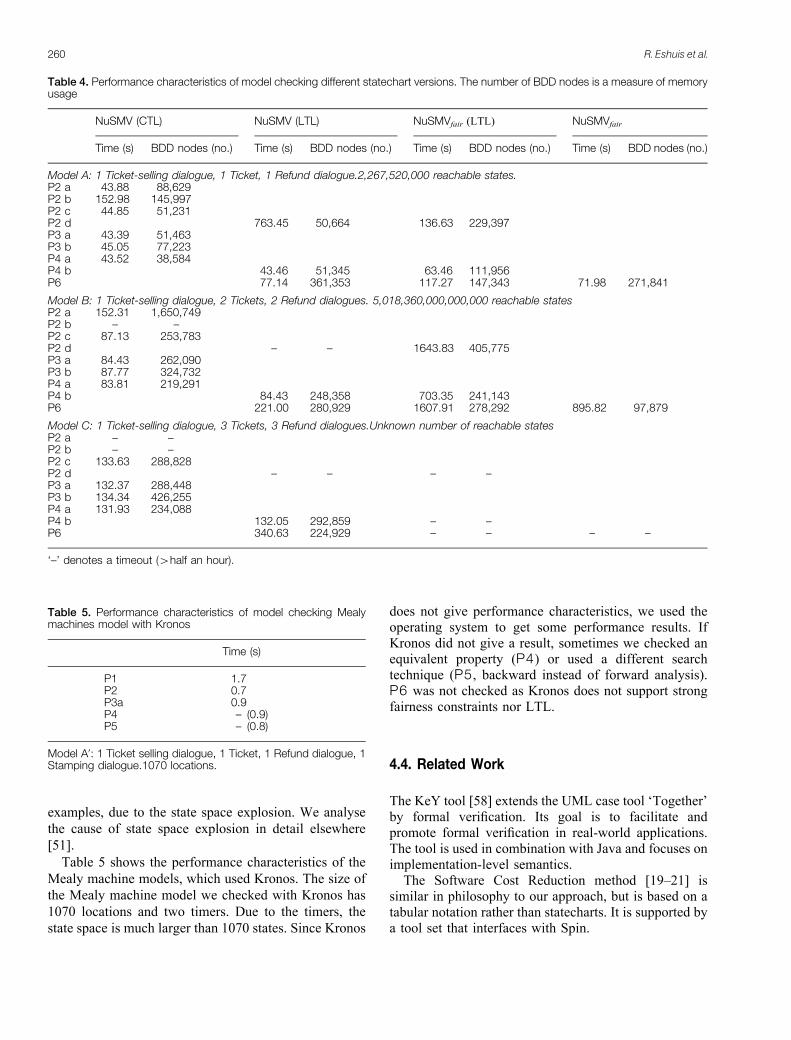
Table 5 shows the performance characteristics of the
Mealy machine models, which used Kronos. The size of
the Mealy machine model we checked with Kronos has
1070 locations and two timers. Due to the timers, the
state space is much larger than 1070 states. Since Kronos
does not give performance characteristics, we used theoperating system to get some performance results. IfKronos did not give a result, sometimes we checked anequivalent property (P4) or used a different searchtechnique (P5 , backward instead of forward analysis).P6 was not checked as Kronos does not support strongfairness constraints nor LTL.
4.4. Related Work
The KeY tool [58] extends the UML case tool ‘Together’by formal verification. Its goal is to facilitate andpromote formal verification in real-world applications.The tool is used in combination with Java and focuses onimplementation-level semantics.
The Software Cost Reduction method [19–21] issimilar in philosophy to our approach, but is based on atabular notation rather than statecharts. It is supported bya tool set that interfaces with Spin.
Table 4. Performance characteristics of model checking different statechart versions. The number of BDD nodes is a measure of memoryusage
NuSMV (CTL) NuSMV (LTL) NuSMVfair (LTL) NuSMVfair
Time (s) BDD nodes (no.) Time (s) BDD nodes (no.) Time (s) BDD nodes (no.) Time (s) BDD nodes (no.)
Model A: 1 Ticket-selling dialogue, 1 Ticket, 1 Refund dialogue.2,267,520,000 reachable states.P2 a 43.88 88,629P2 b 152.98 145,997P2 c 44.85 51,231P2 d 763.45 50,664 136.63 229,397P3 a 43.39 51,463P3 b 45.05 77,223P4 a 43.52 38,584P4 b 43.46 51,345 63.46 111,956P6 77.14 361,353 117.27 147,343 71.98 271,841
Model B: 1 Ticket-selling dialogue, 2 Tickets, 2 Refund dialogues. 5,018,360,000,000,000 reachable statesP2 a 152.31 1,650,749P2 b – –P2 c 87.13 253,783P2 d – – 1643.83 405,775P3 a 84.43 262,090P3 b 87.77 324,732P4 a 83.81 219,291P4 b 84.43 248,358 703.35 241,143P6 221.00 280,929 1607.91 278,292 895.82 97,879
Model C: 1 Ticket-selling dialogue, 3 Tickets, 3 Refund dialogues.Unknown number of reachable statesP2 a – –P2 b – –P2 c 133.63 288,828P2 d – – – –P3 a 132.37 288,448P3 b 134.34 426,255P4 a 131.93 234,088P4 b 132.05 292,859 – –P6 340.63 224,929 – – – –
‘–’ denotes a timeout (4half an hour).
Table 5. Performance characteristics of model checking Mealymachines model with Kronos
Time (s)
P1 1.7P2 0.7P3a 0.9P4 – (0.9)P5 – (0.8)
Model A’: 1 Ticket selling dialogue, 1 Ticket, 1 Refund dialogue, 1Stamping dialogue.1070 locations.
260 R. Eshuis et al.

Chan et al. [43] have model checked a single RSMLstatechart by defining a mapping from statechart syntaxto the SMV input syntax, which makes model checkingvery efficient. We have used this encoding for ourexample. They only use CTL whereas we use CTL, LTLand strong fairness constraints. We do not know whetherthey have implemented this mapping in a statechartediting tool. Finally, they do not embed their approach ina method.
Latella et al. [59] model check UML statecharts usingSpin. They do not focus on how the model checker isintegrated with the UML design tool. Their statechartsemantics does not handle multiple statecharts or realtime.
Lilius and Porres Paltor [53] have developed a tool tomodel check UML statecharts using Spin. The tool theydeveloped translates counterexamples returned by Spinback in terms of sequence diagrams. It is unclearwhether the tool is integrated with a UML design tool.
5. Conclusions and Further Work
5.1. Summary
In this paper we presented a requirements-levelsemantics for object-oriented statecharts and showedthat it can be used for requirements-level modelchecking in a goal-oriented approach. Model checkingcan be used to uncover hidden assumptions in formalrequirements specification. It can also be used to identifyambiguities in an informal specification. It is useful inthis respect to have different people produce aformalisation of one set of informally specified proper-ties. Our example specification briefly illustrates the wayin which formal and informal elements of a systemspecification can be combined.
5.2. Maturity of Model Checkers
Our experience with model checking is that it is not yetthe push-button technology that some of us would like itto be. When we formalise assumptions A, a specificationS and desired properties E, we would like a modelchecker to tell us whether A ^ S � E and, if theentailment does not hold, give us a counterexample.However, in actual practice we found that the modelcheckers that we used had to be used ‘smartly’ in orderto produce the desired result. We defined a generalformat for the LTS that, with minor adaptations, can beinput to various model checkers. However, this inputformat is very inefficient in memory usage. NuSMV is asymbolic model checker, which can be given a muchmore efficient input by encoding our LTS semantics
symbolically, using the input language of NuSMVoptimally. Therefore, in this paper we have used thesymbolic encoding for statecharts that has been definedby Chan et al. for RSML [43]. This decreased theamount of time and memory needed significantly, butnot enough. NuSMV is sensitive to the order in whichthe state variables are declared. Two different orderingsmay differ wildly in their model checking executiontime, with differences between seconds or days to verifya property. We checked properties with NuSMV usingan efficient ordering, which we found after a fewiterations in which we used NuSMV interactively and letNuSMV itself reorder the ordering of variables while itwas building an internal model for model checking.These experiences indicate that the ideal of adding auser-friendly front end such as TCM to a set of modelcheckers is currently not yet attainable. However, weexpect the technology to improve in the near future andwe think NuSMV is a suitable tool to check properties ofstatecharts. Kronos is not a symbolic model checker andcould only be used for a simplified version of the model.
5.3. Further Work
We plan to extend our tool support for model checkingin various ways. First, we intend to interface Kronosdirectly with the statechart editor. Second we intend touse Spin for model-checking statecharts, as Spin is usedquite frequently in other approaches that model checkstatecharts. Third, we are currently working on toolsupport for translating the feedback of the model checkerinto a UML sequence diagram. Fourth, we plan to lookat model checking of creation and deletion of objects, byapplying some recent work of DiStefano et al. [56].
Another plan for future work is to provide support inthe specification of properties in the form of templates offrequently occurring properties. Dwyer et al. [60] havefound a list of eight patterns in temporal properties andin the KAOS project [15,45] goal-oriented refinementpatterns have been identified. We intend to look at theproblem frames identified by Jackson [18] to see if wecan build a library of formally verified patterns, plusguidelines to recognise and use these patterns.
Acknowledgements. Rik Eshuis was supported by NWO/SION, grantno. 612-62-02 (DAEMON). David Jansen was partially supported byNWO/SION, grant no. 612-323-419 (DEIRDRE).
References
1. Harel D. Statecharts: a visual formalism for complex systems. SciComput Program 1987;8(3):231–274
2. Harel D, Pnueli A. On the development of reactive systems. In:Apt K (ed). Logics and models of concurrent systems. NATO ASISeries. Springer, Berlin, 1985, pp 477–498
Requirements-Level Semantics Object-Oriented Statecharts 261

3. Rumbaugh J, Blaha M, Premerlani W, Eddy F, Lorensen W.Object-oriented modeling and design. Prentice-Hall, EnglewoodCliffs, NJ, 1991
4. Rumbaugh J, Jacobson I, Booch G. The Unified ModelingLanguage reference manual. Addison-Wesley, Reading, MA,1999
5. von der Beeck M. A comparison of statecharts variants. In:Langmaack H, de Roever W-P, Vytopil J (eds). Formaltechniques in real-time and fault-tolerant systems. LectureNotes in Computer Science 863. Springer, Berlin, 1994, pp128–148
6. OMG. Action semantics for the UML (OMG ad/2001-03-01),2001. URL: http://www.umlactionsemantics.org
7. Dehne F, Wieringa R, van de Zandschulp H. Toolkit forconceptual modeling (TCM): user’s guide and reference.Technical report, University of Twente, 2000. URL: http://www.cs.utwente.nl/~tcm
8. McMillan KL. Symbolic model checking. Kluwer, Dordrecht,1993
9. Cimatti A, Clarke E, Giunchiglia F, Roveri M. NuSMV: a newsymbolic model checker. Int J Software Tools Technol Transfer2000;2(4):410–425
10. Yovine S. KRONOS: a verification tool for real-time systems. IntJ Software Tools Technol Transfer 1997;1(1/2):123–133
11. Smith CJ. Synonyms discriminated. G. Bell, London, 192612. Harel D, Rumpe B. Modeling languages: syntax, semantics and
all that stuff. Part I: The basic stuff. Technical report MCS00-16,Weizmann Institute of Science, 2000. URL: http://www.wis-dom.weizmann.ac.il/~harel
13. Wieringa RJ. Postmodern software design with NYAM: not yetanother method. In Broy M, Rumpe B (eds). Requirementstargeting software and systems engineering. Lecture Notes inComputer Science 1526. Springer, Berlin, 1998, pp 69–94
14. Wieringa RJ. Design methods for software systems: Yourdon,Statemate and the UML. Morgan Kaufmann, San Mateo, CA, (tobe published)
15. Darimont R, van Lamsweerde A. Formal refinement patterns forgoal-driven requirements elaboration. In: Fourth ACM sympo-sium on the foundations of software engineering (FSE4), 1996, pp179–190
16. van Lamsweerde A, Darimont R, Massonet P. Goal-directedelaboration of requirements for a meeting scheduler: problemsand lessons learnt. In: Proceedings of the second IEEEinternational symposium on requirements engineering, IEEEComputer Society Press, Los Alamitos, CA, 1995
17. Gunter CA, Gunter EL, Jackson MA, Zave P. A reference modelfor requirements and specifications. IEEE Software 2000;17(3):37–43
18. Jackson MA. Problem frames: analysing and structuring softwaredevelopment problems. Addison-Wesley, Reading, MA, 2000
19. Heitmeyer C, Kirby J, Labaw B, Bharadwaj R. SCR: a toolset forspecifying and analyzing software requirements. In: Hu AJ, VardiMY (eds). Proceedings of the 10th international computer aidedverification conference. Lecture Notes in Computer Science 1427.Springer, Berlin, 1998, pp 526–531
20. Heitmeyer CL, Jeffords RD, Labaw BG. Automated consistencychecking of requirements specifications. ACM Trans SoftwareEng Methodol 1996;5(3):231–261
21. Parnas DL, Madey J. Functional documents for computersystems. Sci Comput program 1995;25:41–61
22. McMenamin SM, Palmer JF. Essential systems analysis. YourdonPress/Prentice-Hall, Englewood Cliffs, NJ, 1984
23. Berry G, Gonthier G. The ESTEREL synchronous programminglanguage: design, semantics, implementation. Sci ComputProgram 1992;19(2):87–152
24. Harel D, Naamad A. The Statemate semantics of statecharts.ACM Trans Software Eng Methodol 5(4):293–333
25. OMG. Unified Modeling Language version 1.4, 200126. Eshuis R, Wieringa R. Requirements-level semantics for UML
statecharts. In: Smith S, Talcott C (eds). Proceedings ofFMOODS 2000, IFIP TC6/WG6.1. Kluwer, Dordrecht, 2000,pp 121–140
27. Damm W, Josko B, Hungar H, Pnueli A. A compositional real-time semantics of Statemate designs. In: de Roever W-P,Langmaack H, Pnueli A (eds). Proceedings of COMPOS ’97.Lecture Notes in Computer Science 1536. Springer, Berlin, 1998,pp 186–238
28. Harel D, Gery E. Executable object modeling with statecharts.IEEE Comput 1997;30(7):31–42
29. Selic B, Gullekson G, Ward P. Real-time object orientedmodeling. Wiley, New York, 1994
30. Eshuis R, Wieringa R. Requirements-level semantics for UMLstatecharts. Technical report TR-CTIT-00-07, University ofTwente, 2000
31. Elmasri R, Navathe SB. Fundamentals of database systems, 2ndedn. Benjamin Cummings, Redwood City, CA, 1994
32. Pnueli A, Shalev M. What is in a step: on the semantics ofstatecharts. In Ito T, Meyer AR (eds). Theoretical aspects ofcomputer software. Lecture Notes in Computer Science 526.Springer, Berlin, 1991, pp 244–265
33. Leveson NL, Heimdahl MPE, Hildreth H, Reese JD. Require-ments specification for process-control systems. IEEE TransSoftware Eng 1994;20(9):684–707
34. Wieringa R, Broersen J. A minimal transition system semanticsfor lightweight class- and behavior diagrams. In: Broy M,Coleman D, Maibaum TSE, Rumpe B (eds). Proceedings ofPSMT’98, Technische Universitat Munchen, TUM-I9803, 1998
35. von der Beeck M. Formalization of UML-statecharts. In: GogollaM, Kobryn C (eds). Proceedings of ‘UML’ 2001. Lecture Notesin Computer Science 2185. Springer, Berlin, 2001, pp 406–421
36. Kuske S. A formal semantics for UML state machines based onstructured graph transformations. In: Gogolla M, Kobryn C (eds).Proceedings of ‘UML’ 2001. Lecture Notes in Computer Science2185. Springer, Berlin, 2001, pp 241–256
37. Kwon G. Rewrite rules and operational semantics for modelchecking UML statecharts. In: Evans A, Kent S, Selic B (eds).Proceedings ‘UML’ 2000. Lecture Notes in Computer Science1939. Springer, Berlin, 2000, pp 528–540
38. Latella D, Majzik I, Massink M. Towards a formal operationalsemantics of UML statechart diagrams. In: Ciancarini P, FantechiA, Gorrieri R (eds). Proceedings of FMOODS’99, IFIP TC6/WG6.1. Kluwer, Dordrecht, 1999, pp 331–347
39. Lilius J, Porres Paltor I. Formalising UML state machines formodel checking. In: France R, Rumpe B (eds). Proceedings of‘UML’ ’99. Lecture Notes in Computer Science 1723. Springer,Berlin, 1999., pp 430–445
40. Reggio G, Astesiano E, Choppy C, Hussmann H. Analysing UMLactive classes and associated state machines: a lightweight formalapproach. In: Maibaum TSE (ed). Proceedings of FASE 2000.Lecture Notes in Computer Science 1783. Springer, Berlin, 2000,pp 127–146
41. McUmber WE, Cheng BHC. General framework for formalizingUML with formal languages. In: Proceedings of the 23rdinternational conference on software engineering (ICSE ’01).IEEE Computer Society, 2001, pp 433–442
429. Harel D, Kupferman O. On the behavioral inheritance of state-based objects. Technical report MCS99-12, Weizmann Instituteof Science, 1999. URL: http://www.wisdom.weizmann.ac.il/~harel
43. Chan W, Anderson R, Beame P, Burns S, Modugno F, Notkin D,Reese J. Model checking large software specifications. IEEETrans Software Eng 1998;24(7):498–520
44. Lamport L. What good is temporal logic? In: Mason REA (ed).Proceedings of the IFIP congress on information processing.North-Holland, Amsterdam, 1983, pp 657–667
45. Dardenne A, van Lamsweerde A, Fickas S. Goal-directedrequirements acquisition. Sci Comput Program 1993;20(1–2):3–50
46. Kesten Y, Pnueli A, Raviv L. Algorithmic verification of lineartemporal logic specifications. In: Larsen KG, Skyum S, WinskelG (eds). Proceedings of the international colloquium on automata,languages and programming (ICALP ’98). Lecture Notes inComputer Science 1443. Springer, Berlin, 1998, pp 1–16
262 R. Eshuis et al.

47. Alur R, Courcoubetis C, Dill D. Model-checking in dense real-time. Inform Comput 1993;104(1):2–34
48. Jansen DN, Wieringa RJ. Extending CTL with actions and realtime. In: Proceedings on international conference on temporallogic 2000, pp 105–114
49. Asarin E, Maler O, Pnueli A. On discretization of delays in timedautomata and digital circuits. In: de Simone R, Sangiorgi D (eds).Proceedings of Concur ’98. Lecture Notes in Computer Science1466. Springer, Berlin, 1998
50. Henzinger TA, Manna Z, Pnueli A. What good are digital clocks?In: Kuich W (ed). Proceedings of the international colloquium onautomata, languages, and programming (ICALP’92). LectureNotes in Computer Science 623. Springer, Berlin, 1992, pp 545–558
51. Eshuis R, Wieringa R. Verification support for workflow designwith UML activity graphs. In: Proceedings of the 2002international conference on software engineering (ICSE ’02),2002
52. Holzmann GJ. The model checker SPIN. IEEE Trans SoftwareEng 1997;23(5):279–295
53. Lilius J, Porres Paltor I. vUML: a tool for verifying UML models.In: 14th IEEE international conference on automated softwareengineering. IEEE Computer Society Press, Los Alamitos, CA,1999, pp 255–258
54. Mikk E, Lakhnech Y, Siegel M, Holzmann GJ. Implementing
statecharts in promela/spin. In: Proceedings of the second IEEEworkshop on industrial-strength formal specification techniques,1998, pp 90–101
55. Reif W, Stenzel K. Formal methods for the secure application ofJava smartcards, December 1999. URL: http://www.informati-k.uni-ulm.de/pm/kiv/projects/javacard_presentation.ps.gz
56. Distefano D, Rensink A, Katoen J-P. Model checking dynamicallocation and deallocation. CTIT technical report TR-CTIT-01-04, University of Twente, 2002
57. Gabbay D, Pnueli A, Shelah S, Stavi J. The temporal analysis offairness. In: Conference record of the seventh annual ACMsymposium on principles of programming languages, ACM,1980, pp 163–173
58. Ahrendt W, Baar T, Beckert B, Giese M, Habermalz E, Hahnle R,Menzel W, Schmitt PH. The KeY approach: integrating objectoriented design and formal verification. In: Ojeda-Aciego M, deGuzman IP, Brewka G, Moniz Pereira L (eds). Proceedings of theeighth European workshop on logics in AI (JELIA). LectureNotes in Computer Science 1919. Springer, Berlin, 2000, pp 21–36. URL: ftp://ftp.cs.chalmers.se/pub/users/reiner/jelia.ps.gz.
59. Latella D, Majzik I, Massink M. Automatic verification of abehavioural subset of UML statechart diagrams using the SPINmodel-checker. Formal Aspects Comput 1999;11(6):637–664
60. Dwyer MB, Avrunin GS, Corbett JC. Patterns in propertyspecifications for finite-state verification. In: Proceedings of the1999 international conference on software engineering (ICSE’99), ACM, 1999, pp 411–421
Requirements-Level Semantics Object-Oriented Statecharts 263