Embed Size (px)
Citation preview
Research and Development of Micro Additive Manufacturing System Using Direct Light Projector
Jeng-Ywan Jeng2014.08.18
Objective
Very high resolution in a relative large area
Y1: 10mmX10mm working area in 2um/pixel resolution, total 5,000X5,000 pixels.
Y2: 50mmX50mm working area in 0.5um/pixel resolution, total 100,000X100,000 pixels
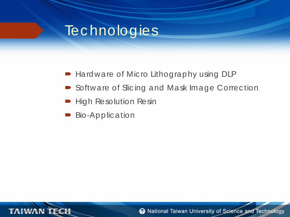
Technologies
Hardware of Micro Lithography using DLP Software of Slicing and Mask Image Correction High Resolution Resin Bio-Application
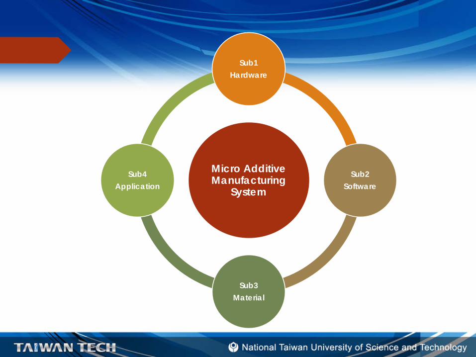
Micro Additive Manufacturing
System
Sub1Hardware
Sub2Software
Sub3Material
Sub4Application

Thanks For Your Attention!
sub-project IHardware Development of Micro Additive Manufacturing System
Jeng-Ywan Jeng2014/8/18
Page 2
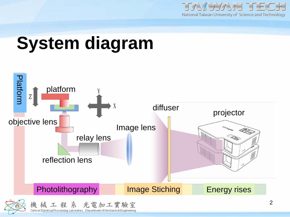
System diagram
Platform
Photolithography Image Stiching Energy rises
platform
objective lens
reflection lens
relay lensImage lens
diffuser projector
2
Page 3
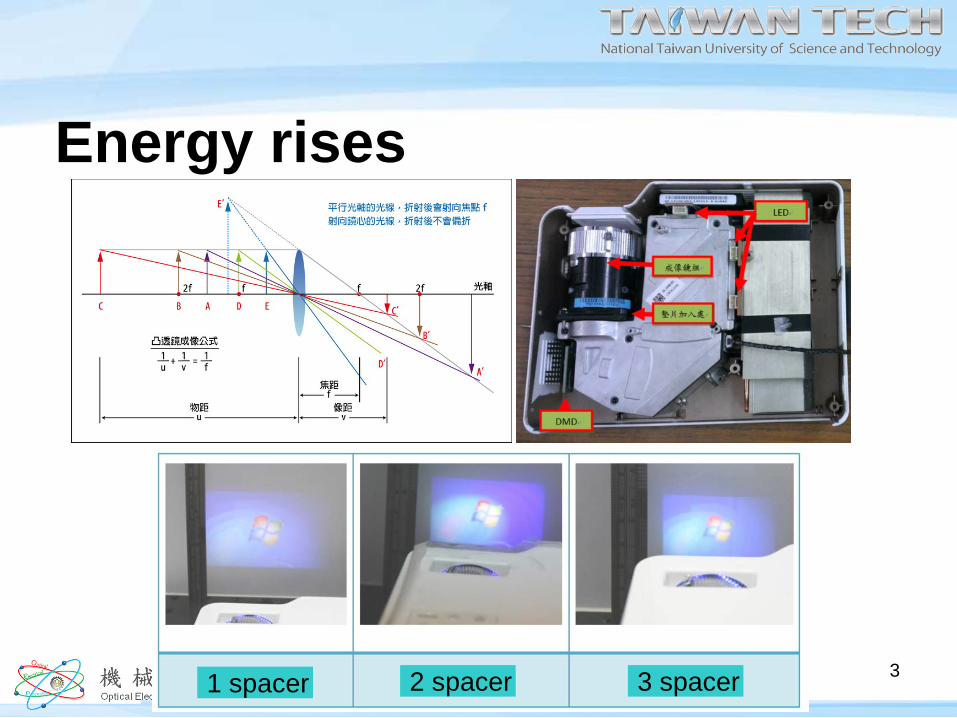
Energy rises
1 spacer 2 spacer 3 spacer 3
Page 4
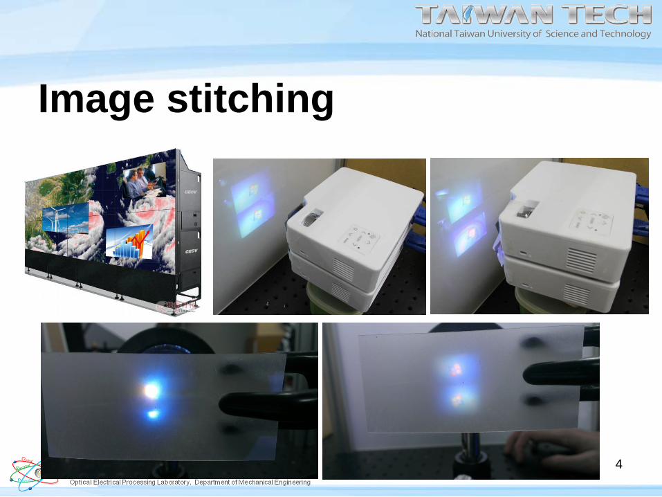
Image stitching
4

Page 5
Lithography imageObjective lens Reflection lens
Relay lenslens
5
Page 6
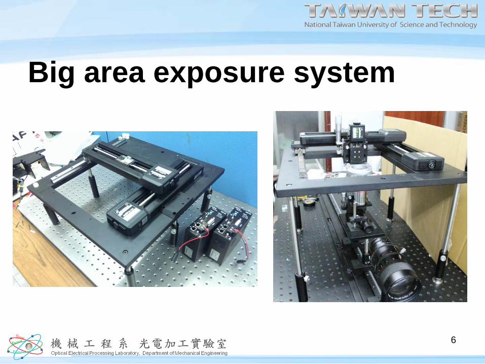
Big area exposure system
6
Page 7
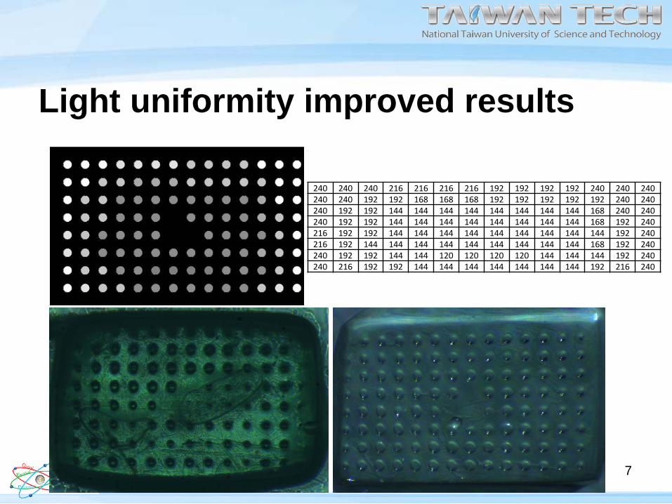
Light uniformity improved results
240 240 240 216 216 216 216 192 192 192 192 240 240 240240 240 192 192 168 168 168 192 192 192 192 192 240 240240 192 192 144 144 144 144 144 144 144 144 168 240 240240 192 192 144 144 144 144 144 144 144 144 168 192 240216 192 192 144 144 144 144 144 144 144 144 144 192 240216 192 144 144 144 144 144 144 144 144 144 168 192 240240 192 192 144 144 120 120 120 120 144 144 144 192 240240 216 192 192 144 144 144 144 144 144 144 192 216 240
7
Page 8
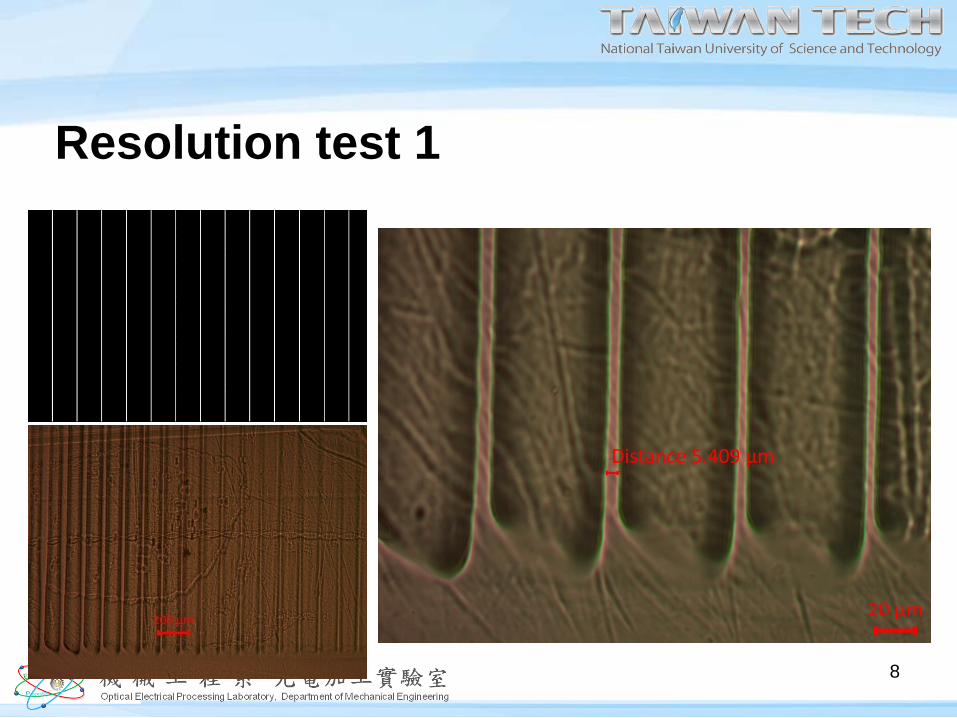
Resolution test 1
8
Page 9
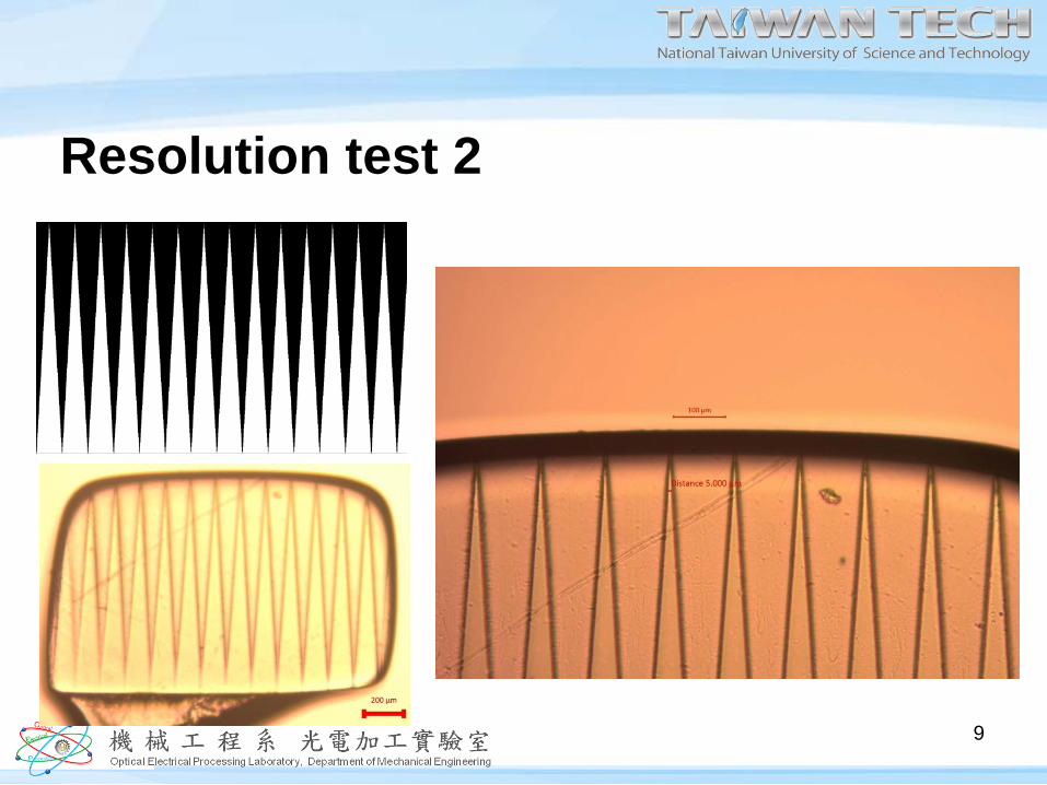
Resolution test 2
9
Page 10
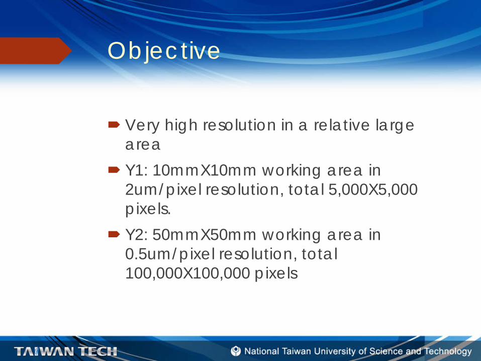
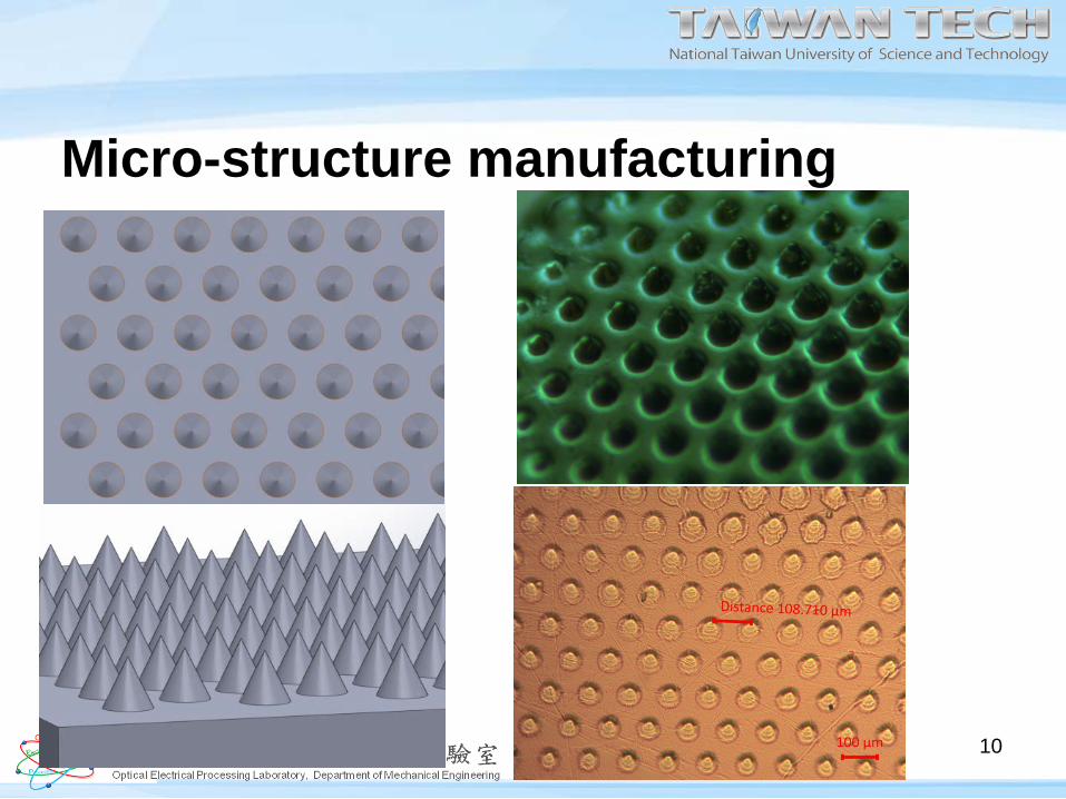
Micro-structure manufacturing
10

Page 11 11
sub-project IISoftware Development of Micro projection type RPJia-Chang Wang2014/8/18
Outlines• Introduction• Image Distortion Correction• Uniform Energy Distribution• Photo Mask Generation (Slicing)• Multi-Image Stitching• Conclusions
2
Introduction - Objective• The objective of the software design is because of the
physical resolution limitation.• If the resulting 3D structures are placed on a 10mmX10mm
area and in resolution of 2μm/pixel, it need 5,000X5,000 resolution of projection image. (Y1)
• If the resulting 3D structures are placed on a 50mmX50mm area and in resolution of 0.5 μm/pixel, it need 100,000X100,000 resolution of projection image.(Y2)
• The dynamic mask generator is based on DLP engine and the resolution is limited. The stepping technique is necessary to this ultra-high resolution application.
• In order to reduce the need of stepping times, it is necessary to combine many projecting images into one.
3
Introduction - Needs• 4 images into 1Image DistortionEnergy DistributionSlicing in different regionStitching
4

IMAGE DISTORTION CORRECTION
Part 1
5
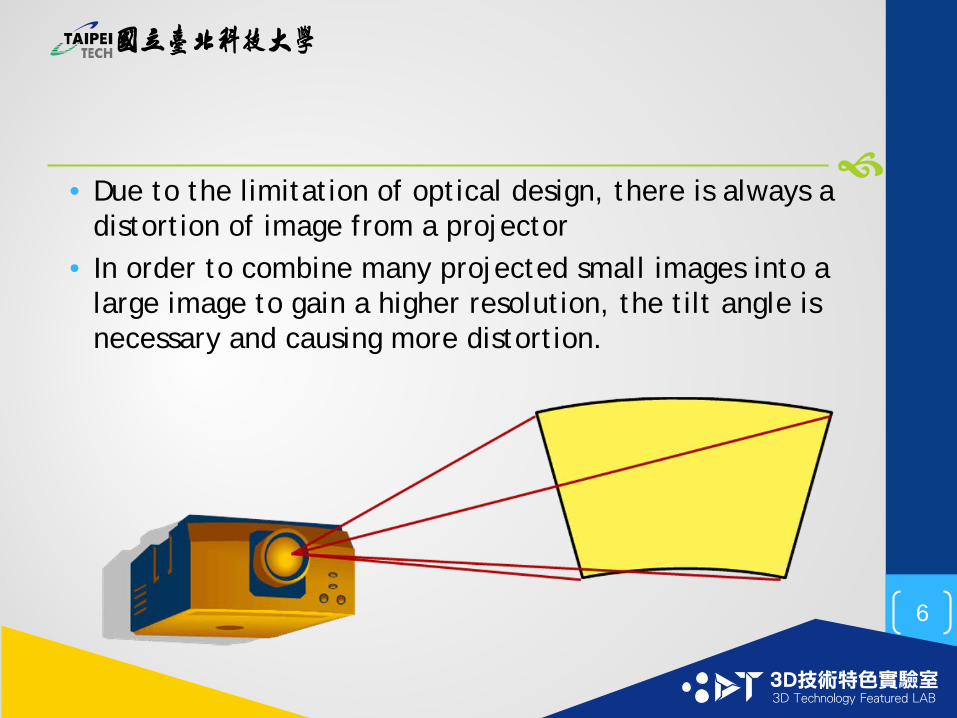
• Due to the limitation of optical design, there is always a distortion of image from a projector
• In order to combine many projected small images into a large image to gain a higher resolution, the tilt angle is necessary and causing more distortion.
6
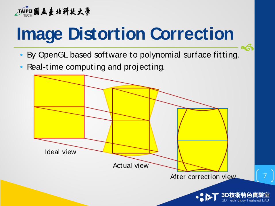
Image Distortion Correction• By OpenGL based software to polynomial surface fitting.• Real-time computing and projecting.
Ideal view
Actual view
After correction view 7
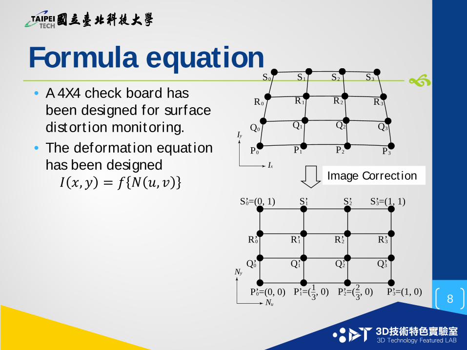
Formula equation• A 4X4 check board has
been designed for surface distortion monitoring.
• The deformation equation has been designed𝐼𝐼 𝑥𝑥,𝑦𝑦 = 𝑓𝑓 𝑁𝑁 𝑢𝑢, 𝑣𝑣
PIx
Iy
Nu
Ny
影像校正
0
Q0
R0
S0
P1
Q1
R1
S1
P2
Q2
R2
S2
P3
Q3
P’=(0, 0)0
Q’0
P’=( , 0)1
Q’1 Q’2
P’=(1, 0)3
Q’3
R3
S3
R’0
S’=(0, 1)0
R’1
S’1
R’2
S’2
R’3
S’=(1, 1)3
13 P’=( , 0)2
23
Image Correction
8
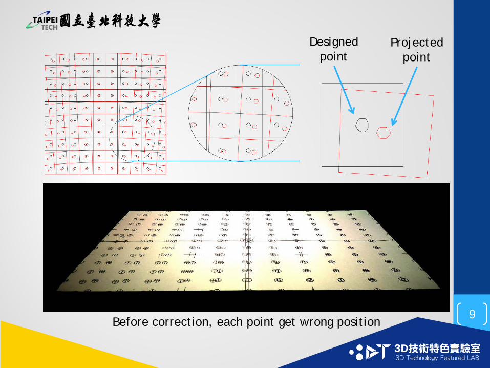
Before correction, each point get wrong position
Designed point
Projected point
9
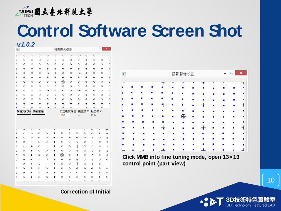
Control Software Screen Shot v.1.0.2
Correction of Initial
Click MMB into fine tuning mode, open 13×13 control point (part view)
10
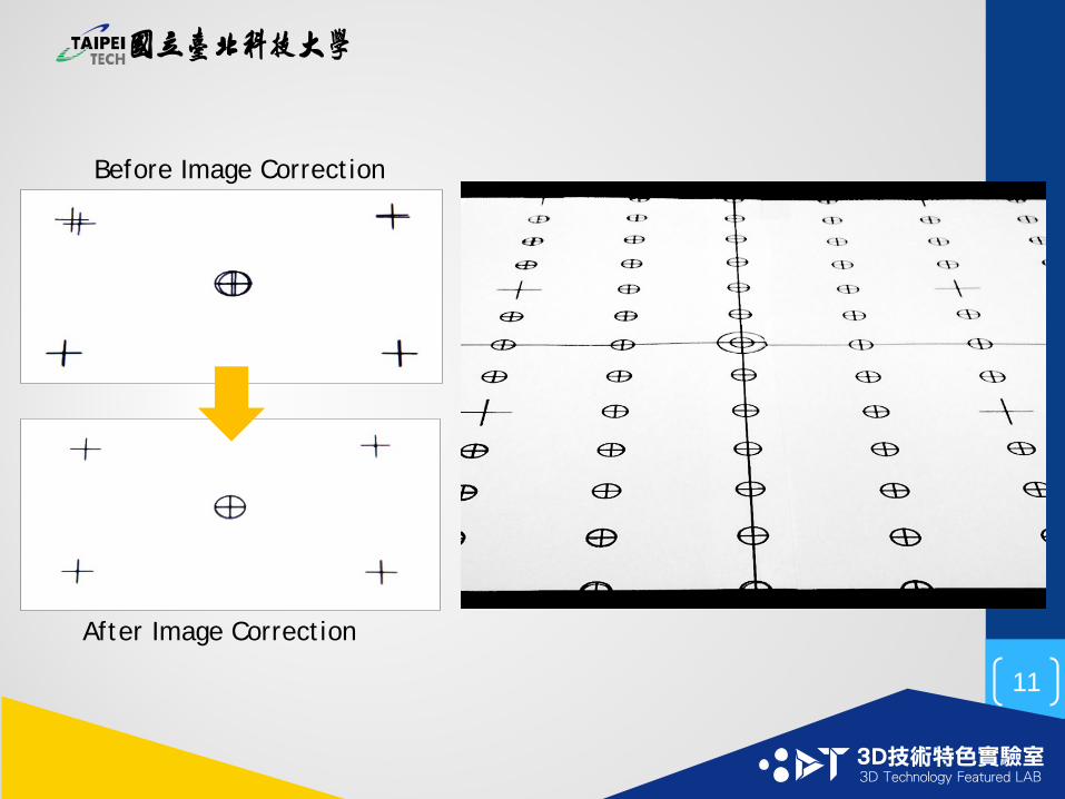
Before Image Correction
After Image Correction
11

UNIFORM ENERGY DISTRIBUTION
Part 2
12
• The image energy uniformity is also a key issue in photo-polymerization to bring a designed thickness everywhere has been exposed.
• The image processing algorithm to solve the physical non-uniform energy distribution problem in necessary.
13
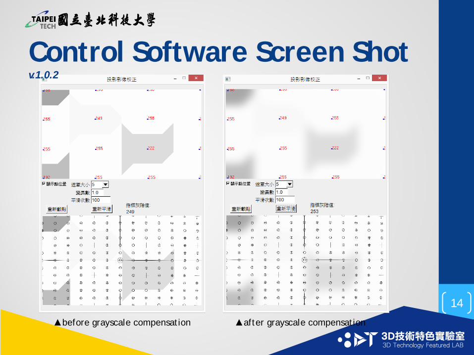
Control Software Screen Shot v.1.0.2
▲before grayscale compensation ▲after grayscale compensation
14
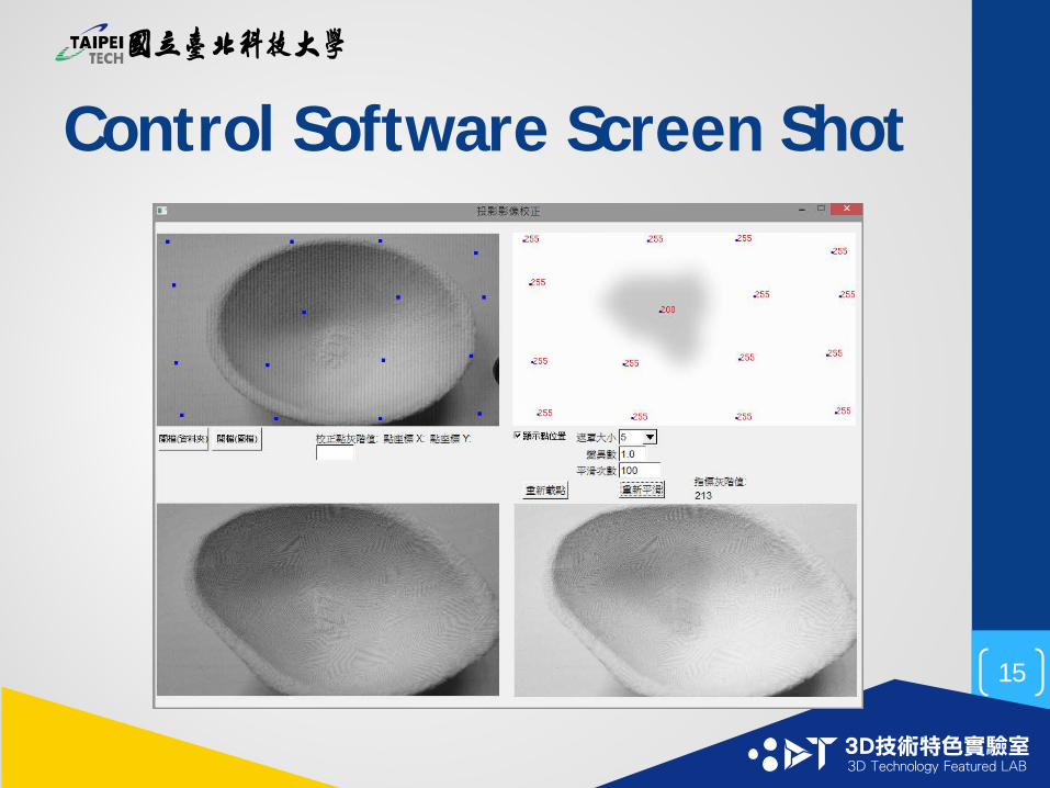
Control Software Screen Shot
15
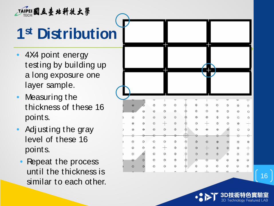
1st Distribution• 4X4 point energy
testing by building up a long exposure one layer sample.
• Measuring the thickness of these 16 points.
• Adjusting the gray level of these 16 points.
• Repeat the process until the thickness is similar to each other.
16
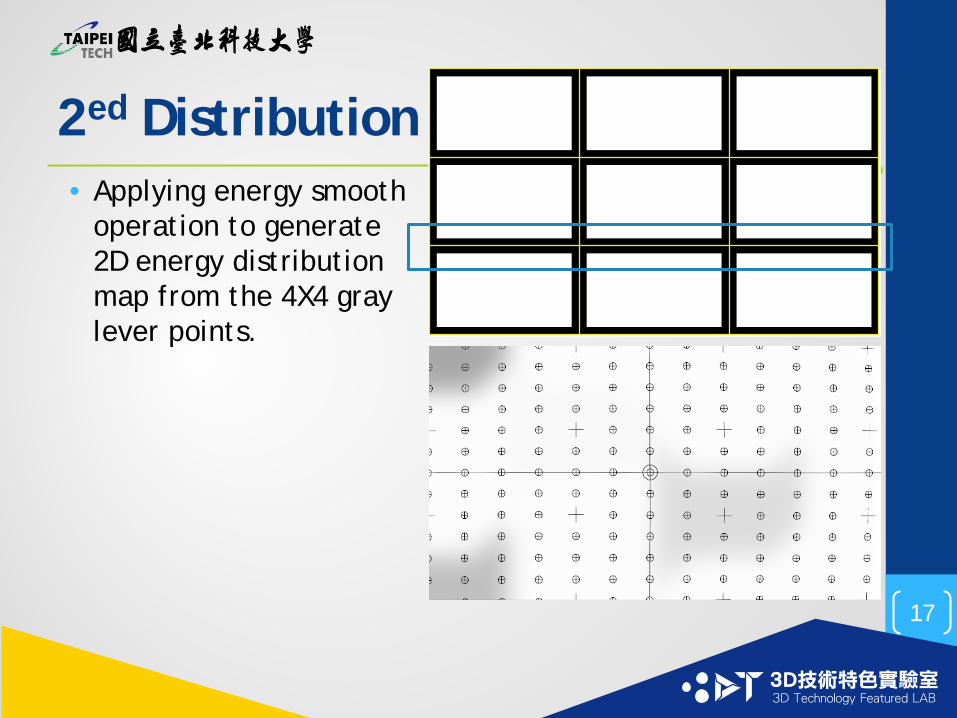
2ed Distribution• Applying energy smooth
operation to generate 2D energy distribution map from the 4X4 gray lever points.
17
PHOTO MASK GENERATION Part III
18
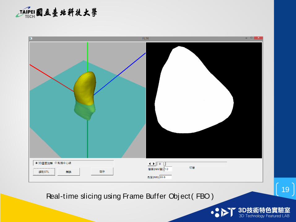
Real-time slicing using Frame Buffer Object( FBO )19
MULTI-IMAGE STITCHINGPart IV
20
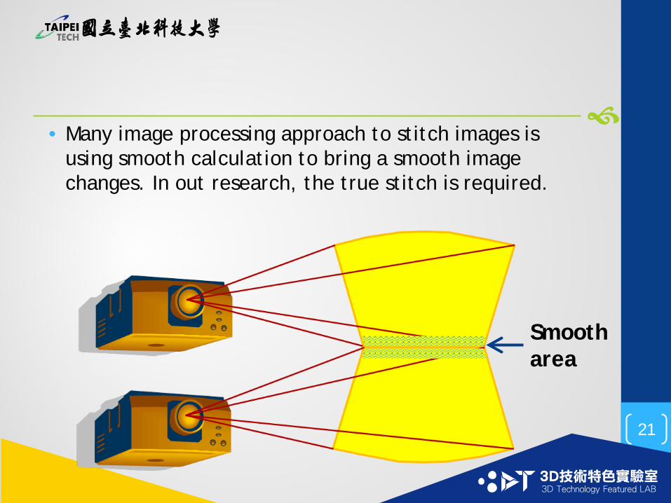
• Many image processing approach to stitch images is using smooth calculation to bring a smooth image changes. In out research, the true stitch is required.
Smooth area
21
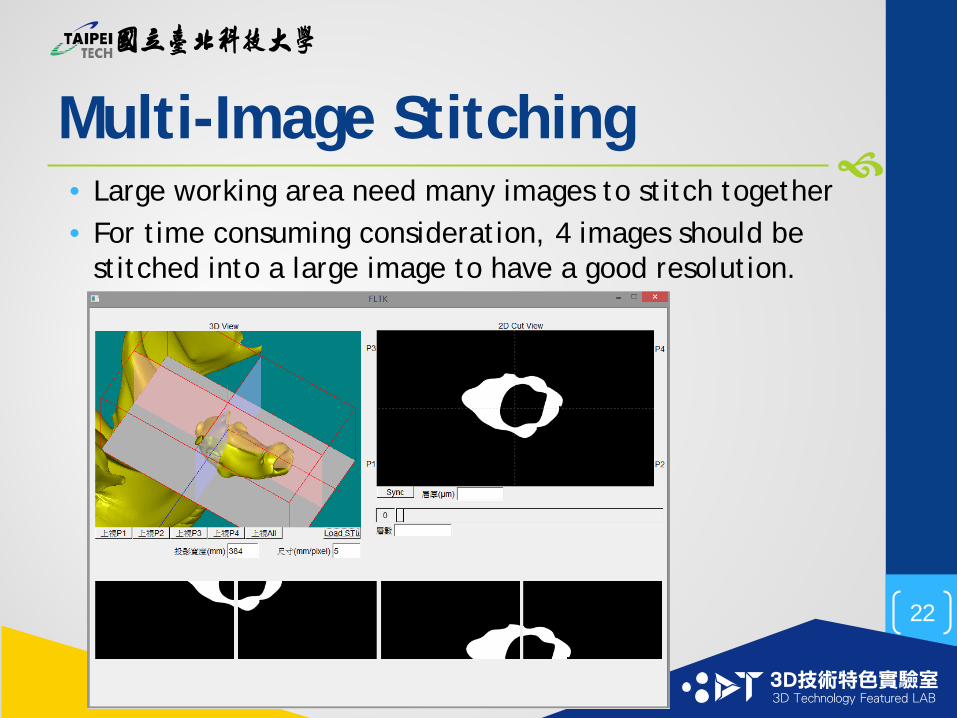
Multi-Image Stitching• Large working area need many images to stitch together• For time consuming consideration, 4 images should be
stitched into a large image to have a good resolution.
22
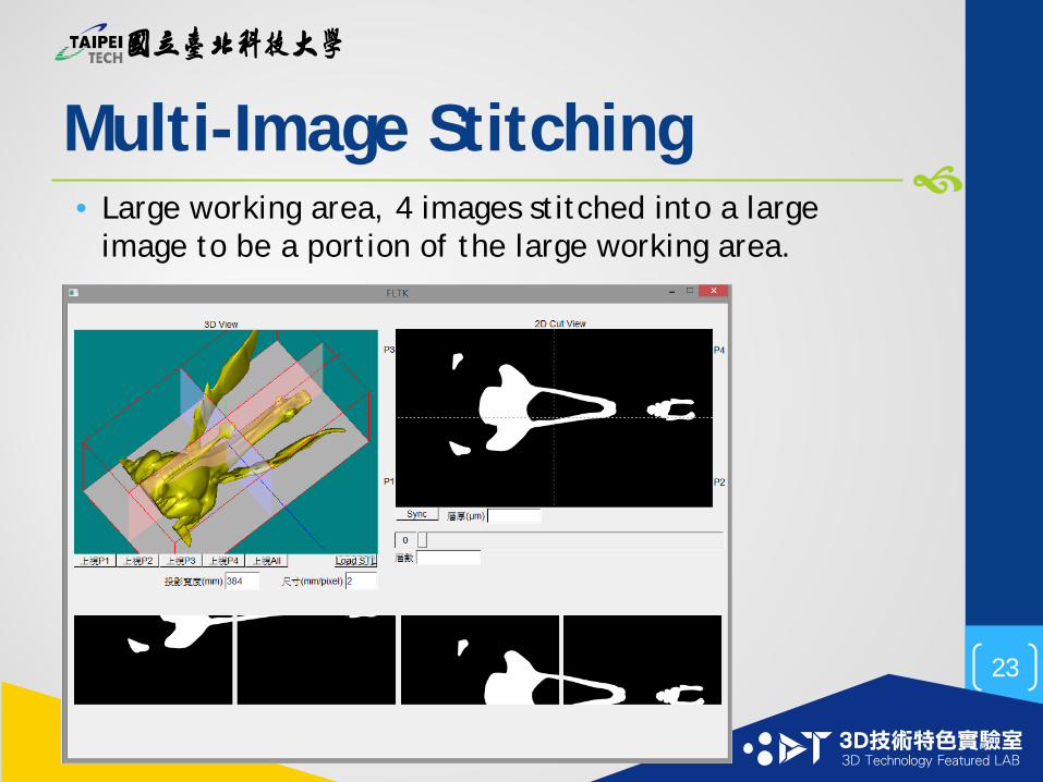
Multi-Image Stitching• Large working area, 4 images stitched into a large
image to be a portion of the large working area.
23
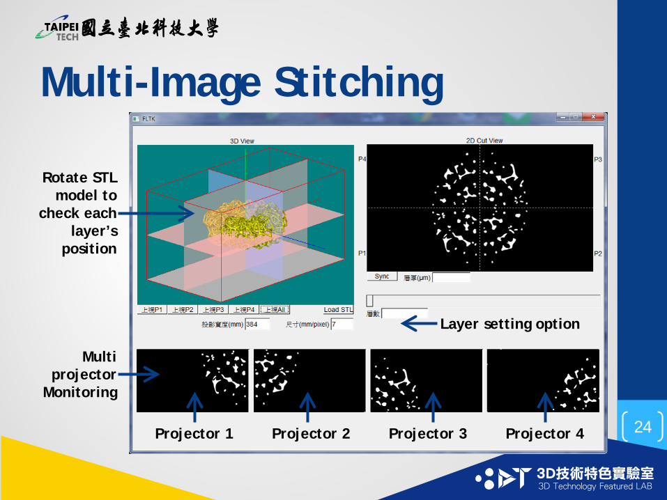
Multi-Image Stitching
Projector 1 Projector 2 Projector 3 Projector 4
Layer setting option
Rotate STL model to
check each layer’s
position
Multi projector
Monitoring
24

CONCLUSIONS
25
Conclusions• The functions of slicing, image distortion, uniform
energy correction, multi-image stitching have been developed in this project.
• The all-in-one program with accepted user interface is under development.
• System integration to work with sub-project 1 is necessary.
Future Work
26
Student :鄭育承(Cheng-Yu, Cheng)Advisor : 蘇威年(Wei-Nien, Wsu)
National Taiwan University of Science and Technology
Sub-Project IIIVisible Photoinitiator –Based On Thioxanthonefor Free Radical Polymerization
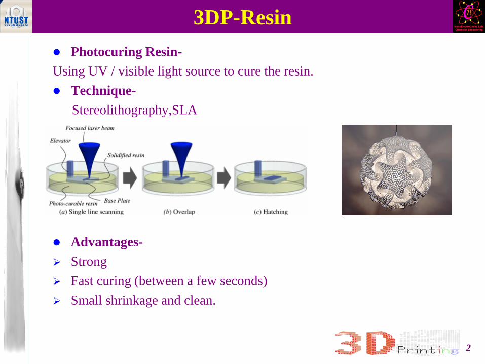
3DP-Resin Photocuring Resin-Using UV / visible light source to cure the resin. Technique-
Stereolithography,SLA
Advantages- Strong Fast curing (between a few seconds) Small shrinkage and clean.
2
IntroductionUV/Visible Light UV Resin disadvantage-Patent issues, expansive, unfriendly for
environment. Photoinitiators for visible light have found particular interest
because of their use in many targeted applications such as dental materials, photoresists, laser-induced 3D curing.
The necessity for such interest lies in the fact that there is no single photoinitiator which fulfills the particular requirements of all industrial applications.
Visible light advantages- Light transmittance Safety Cheaper
3
PhotoinitiatorPhotoinitiators are classified into two general categories1. α-cleavage (Type I) - Reactive species are formed by direct
fragmentation in Type I photoinitiators.2. hydrogen abstraction–type (Type II) - The triplet states of Type II
photoinitiators readily react with a coinitiator to yield the initiating radicals.
Despite acting more slowly as a result of bimolecular radical generation process, Type II photoinitiators possess better optical absorption properties in the ultraviolet-visible (UV-vis) spectral region.
4
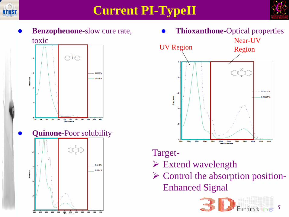
Current PI-TypeII Benzophenone-slow cure rate,
toxic
Quinone-Poor solubility
Thioxanthone-Optical properties
UV RegionNear-UV Region
Target- Extend wavelength Control the absorption position-
Enhanced Signal
5
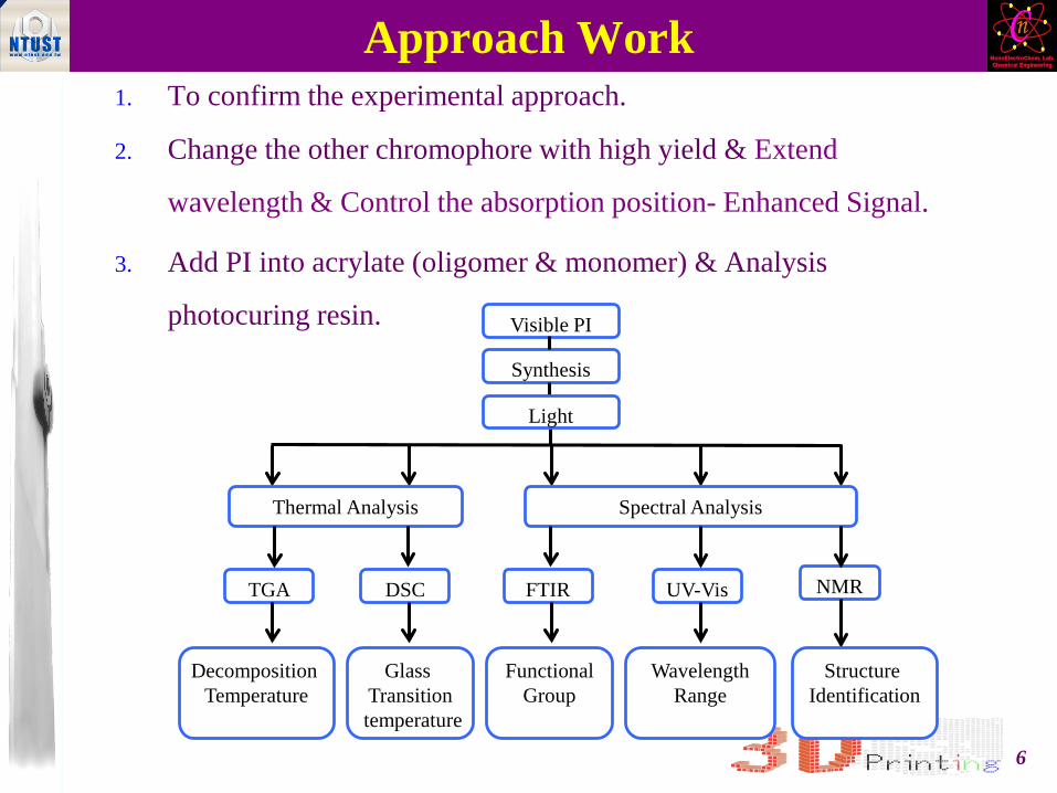
Approach Work1. To confirm the experimental approach.
2. Change the other chromophore with high yield & Extend
wavelength & Control the absorption position- Enhanced Signal.
3. Add PI into acrylate (oligomer & monomer) & Analysis
photocuring resin. Visible PI
Synthesis
TGA
Decomposition Temperature
DSC
Glass Transitiontemperature
FTIR UV-Vis
FunctionalGroup
WavelengthRange
Light
NMR
Structure Identification
Thermal Analysis Spectral Analysis
6
Thanks for your attention.
7
Sub-project IVResearch on Biomedical
Application
Yih-Lin Cheng and Freeman Chen2014.08.18
Outlines
• Introduction• Scaffold Material System• AM System for Scaffold Fabrication• Flow of Micro-pattern Transferring on to Scaffold• Micro-pattern transferring to PDMS Film• Micro-pattern Transferring from PDMS to
Biomaterial• Conclusions

Tissue Engineering
Scaffold
Cells
Growth Factors
Tissue Engineering
Engineering
Scaffolds:• Biodegradable• Biocompatible• Porous• Interconnected pores• Mechanical strength
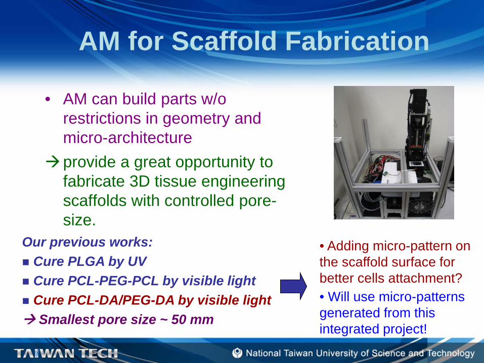
AM for Scaffold Fabrication
• AM can build parts w/o restrictions in geometry and micro-architecture
provide a great opportunity to fabricate 3D tissue engineering scaffolds with controlled pore-size.
Our previous works: Cure PLGA by UV Cure PCL-PEG-PCL by visible light Cure PCL-DA/PEG-DA by visible light Smallest pore size ~ 50 mm
• Adding micro-pattern on the scaffold surface for better cells attachment?• Will use micro-patterns generated from this integrated project!
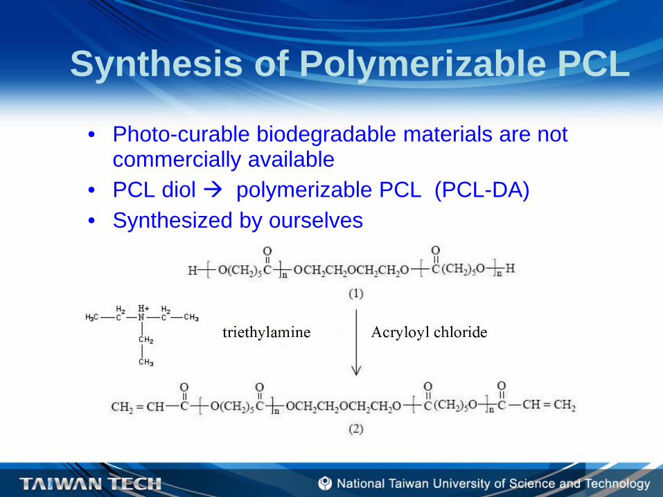
Synthesis of Polymerizable PCL• Photo-curable biodegradable materials are not
commercially available• PCL diol polymerizable PCL (PCL-DA)• Synthesized by ourselves
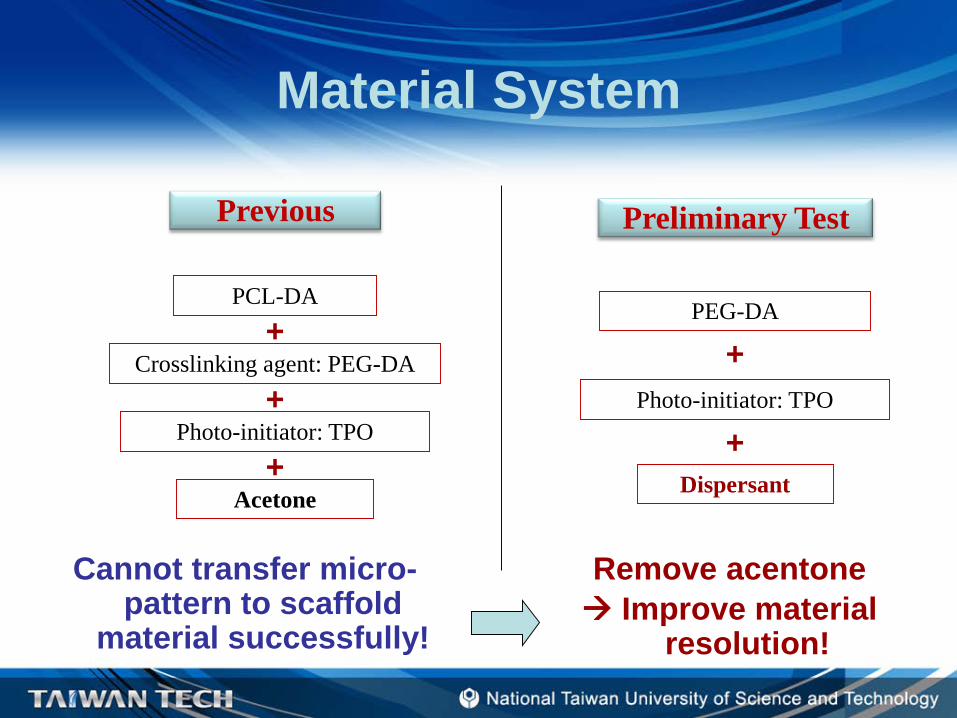
Material System
Cannot transfer micro-pattern to scaffold
material successfully!
Previous Preliminary Test
PCL-DA
Crosslinking agent: PEG-DA
Acetone
Photo-initiator: TPO
+
+
+
Remove acentone Improve material
resolution!
PEG-DA
Dispersant
Photo-initiator: TPO
+
+
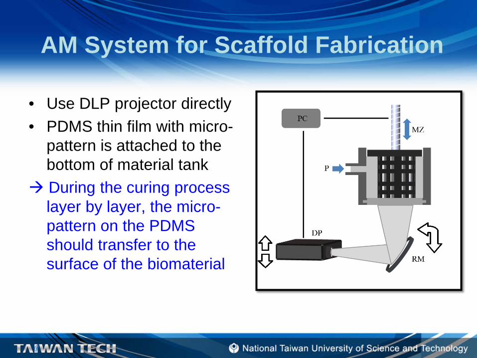
AM System for Scaffold Fabrication
• Use DLP projector directly• PDMS thin film with micro-
pattern is attached to the bottom of material tank
During the curing process layer by layer, the micro-pattern on the PDMS should transfer to the surface of the biomaterial
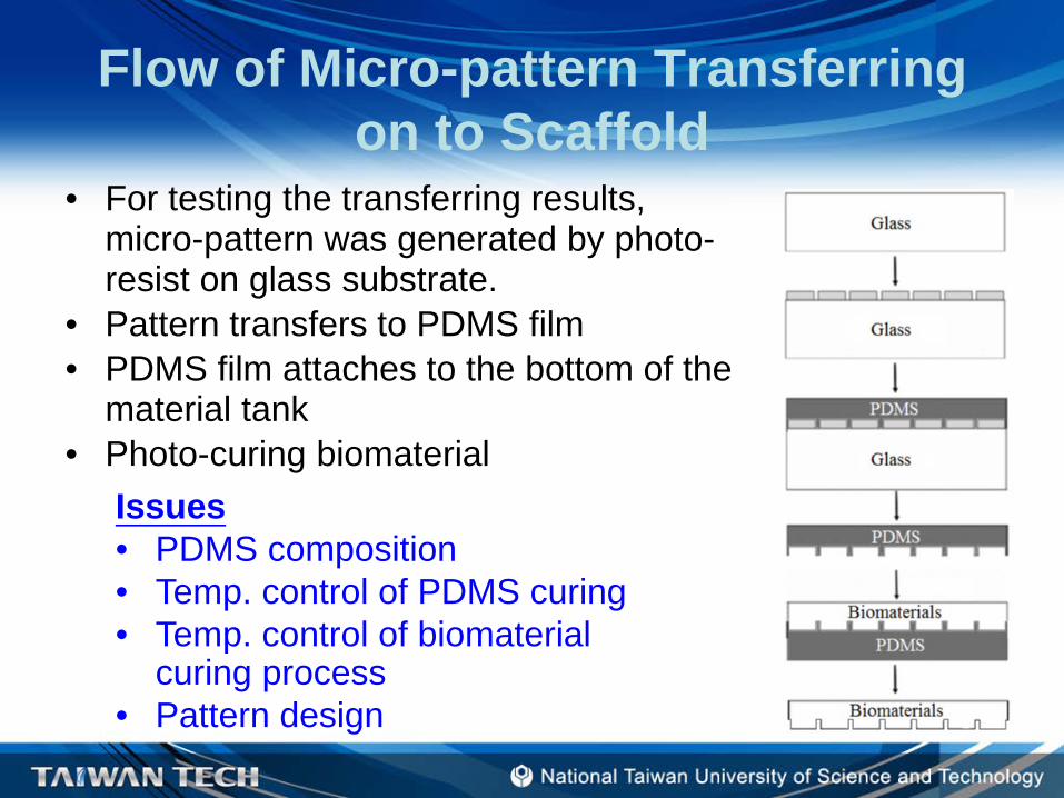
Flow of Micro-pattern Transferring on to Scaffold
• For testing the transferring results, micro-pattern was generated by photo-resist on glass substrate.
• Pattern transfers to PDMS film• PDMS film attaches to the bottom of the
material tank• Photo-curing biomaterial
Issues• PDMS composition• Temp. control of PDMS curing • Temp. control of biomaterial
curing process• Pattern design
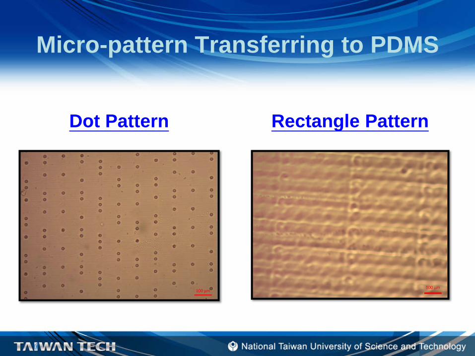
Micro-pattern Transferring to PDMS
Dot Pattern Rectangle Pattern
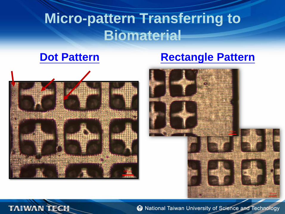
Micro-pattern Transferring to Biomaterial
Dot Pattern Rectangle Pattern
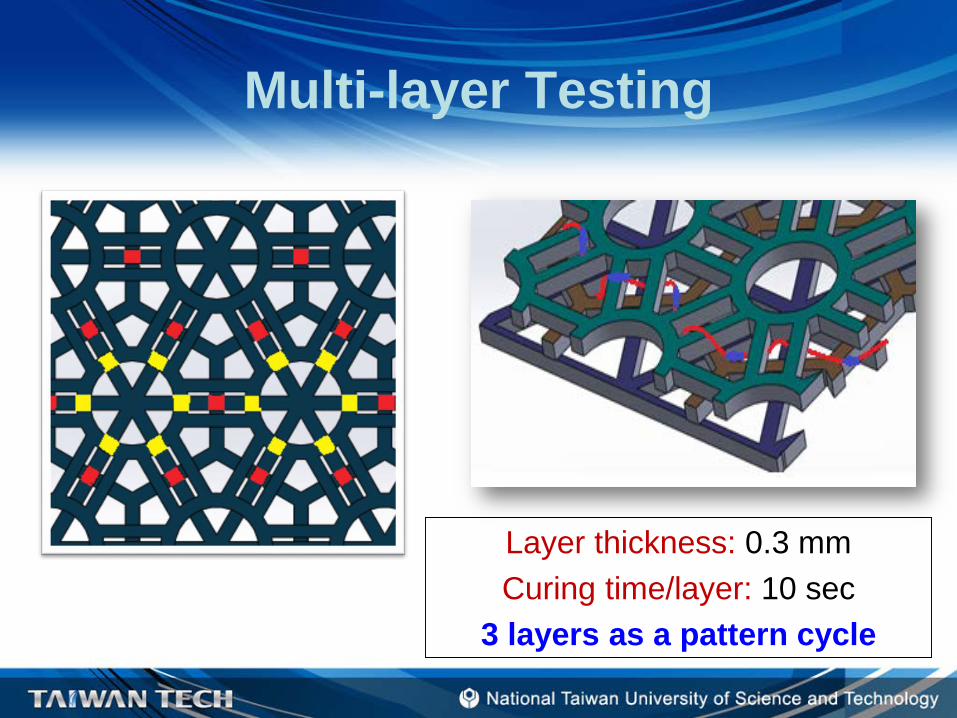
Multi-layer Testing
Layer thickness: 0.3 mmCuring time/layer: 10 sec
3 layers as a pattern cycle
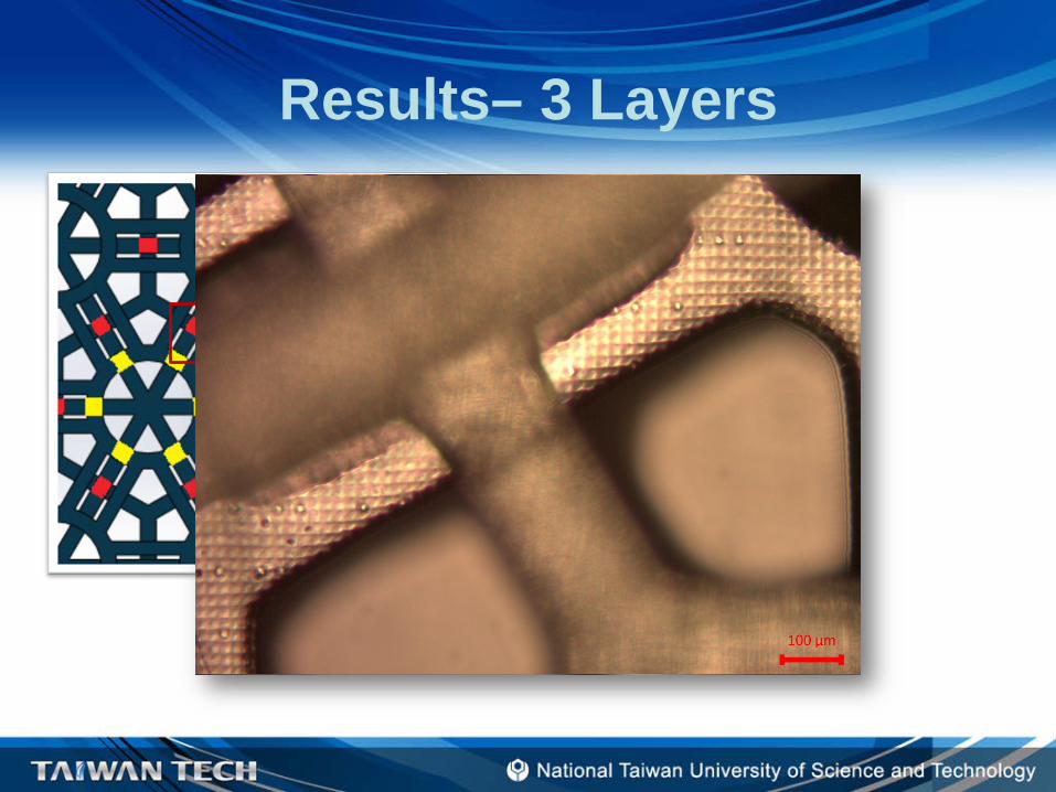
Results– 3 Layers
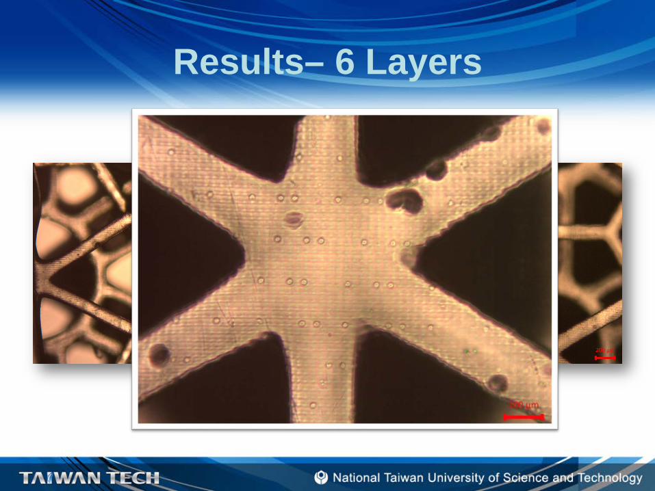
Results– 6 Layers

Results– 9 Layers
Conclusions• Studying on applying micro-pattern into biomedical
application – tissue engineering scaffold fabrication • Micro-pattern transfers to PDMS and biomaterial are
feasible!• Two types of patterns were studied.Future works:• Design of different micro-patterns• Adding PCL-DA into the material system w/o acetone• Cell culturing tests to understand the effects of existence
of micro-patterns • Use the micro-patterns generated by this integrated
project.

Thanks For Your Attention!