Embed Size (px)
Citation preview
Hindawi Publishing CorporationJournal of Electrical and Computer EngineeringVolume 2013 Article ID 382913 10 pageshttpdxdoiorg1011552013382913
Research ArticleA Compact Versatile Six-Port Radar Module forIndustrial and Medical Applications
Sarah Linz1 Gabor Vinci2 Sebastian Mann1 Stefan Lindner1 Francesco Barbon1
R Weigel1 and Alexander Koelpin1
1 Institute for Electronics Engineering University of Erlangen-Nuremberg 91058 Erlangen Germany2 InnoSenT GmbH Am Roedentor 30 97499 Donnersdorf Germany
Correspondence should be addressed to Sarah Linz sarahlinzfaude
Received 4 October 2013 Accepted 21 November 2013
Academic Editor Adriana Serban
Copyright copy 2013 Sarah Linz et al This is an open access article distributed under the Creative Commons Attribution Licensewhich permits unrestricted use distribution and reproduction in any medium provided the original work is properly cited
The Six-port receiver has been intensively investigated in the last decade to be implemented as an alternative radar architecturePlenty of current scientific publications demonstrate the effectiveness and versatility of the Six-port radar for special industrialautomotive and medical applications ranging from accurate contactless vibration analysis through automotive radar calibrationto remote breath and heartbeat monitoring Its highlights such as excellent phase discrimination trivial signal processing lowcircuit complexity and cost have lately drawn the attention of companies working with radar technology A joint project involvingthe University of Erlangen-Nuremberg and InnoSenT GmbH (Innovative Sensor Technology) led to the development of a highlyaccurate compact and versatile Six-port radar module aiming at a reliable high-integration of all subcomponents such as antennaSix-port front-end baseband circuitry and digital signal processing in one single package Innovative aspects in the RF front-enddesign as well as in the integration strategy are hereby presented together with a system overview and measurement results
1 Introduction
Optical high-resolution contactless distance measurementtechniques such as laser interferometry and laser pulse time-difference measurements have been widely implementedfor industrial and medical applications The drawback ofoptical techniques is the difficulty to penetrate dust andfog with the laser in harsh environments as optical lensesand mirrors can get dirty Furthermore with increasingsuspended particle density in the propagation environmentdampening and scattering effects increase so that the lasercannot reach the surface of the object under investigationThese inconveniences of laser based systems are the cause ofan increasing interest in alternative nonoptical measurementtechniques that are robust against such industrial environ-ment conditions
One of the main noncontact-based alternatives to laser isradar Radar-based measurement techniques work also whena direct optical line of sight to the object under investigationis not guaranteed since radar waves can propagate much
better through foggy or dusty air Furthermore even bulkyand optically nontransparent dielectric slabs or nonmetallicshields can be penetrated by the radar signal [1 2]
Within the last decade radar technology has been rapidlyexpanding in industrial automotive andmedical applicationareas [3] Advanced positioning and sensor feedback tasksin automation processes rely on high precision radar-baseddistance detection for example to measure and track themovement of robots [4] As an example for medical applica-tions high measurement accuracy is required to guaranteethe safety of patients and the quality of therapies throughvital sign monitoring systems For instance heartbeat andbreath rate monitoring is of primary interest and can beachievedwith particularly accurate radar-based displacementdetection techniques [5]
The Six-port receiver recently raised the interest of theindustry [6] The excellent phase resolution offered by thisalternative microwave receiver leads to high accuracy dis-tance and angular measurement capabilities [7] Historicallythe Six-port receiver has been used as a reflectometer [8 9]
2 Journal of Electrical and Computer Engineering
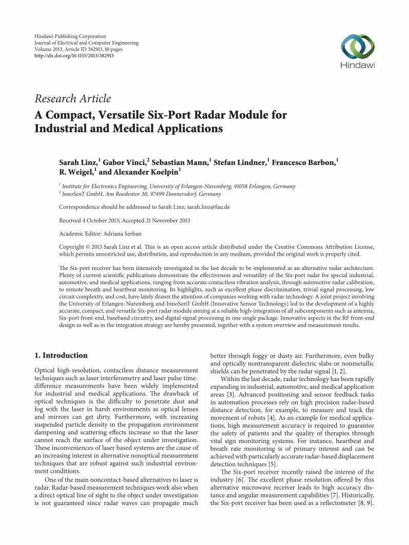
Figure 1 The developed Six-port radar module
Following the evolution of radar and microwave technologythe Six-port receiver has been also used as an alternativevector network analyzer for sensing applications Mainly dueto the progress in material and process technology the Six-port technique has lately found several other implementationpossibilities As a result of a joint project involving theUniversity of Erlangen-Nuremberg and InnoSenT GmbH(Innovative Sensor Technology) a radar sensor based on theSix-port technique has been developed (Figure 1)
In this work this compact and versatile Six-port radarsystem is presented along with design and simulation resultsof its passive components as well as hardware measurementsand evaluations The principles of Six-port receivers aswell as the use of Six-port networks for radar applicationshave already been shown in many publications [9ndash11] Thedeveloped monostatic Six-port radar front-end works in theISM band at 24GHz It can be used in one-target scenariosfor distance and vibration measurements [12] After using asuitable calibration the position and movement of a targetcan be calculated [11]
2 System Overview
The presented sensor is a monostatic Six-port radar withintegrated patch antenna array microwave front-end anddigital signal processing (DSP) board in one compact casemeasuring only (40 times 60 times 44)mm3 (width length height)
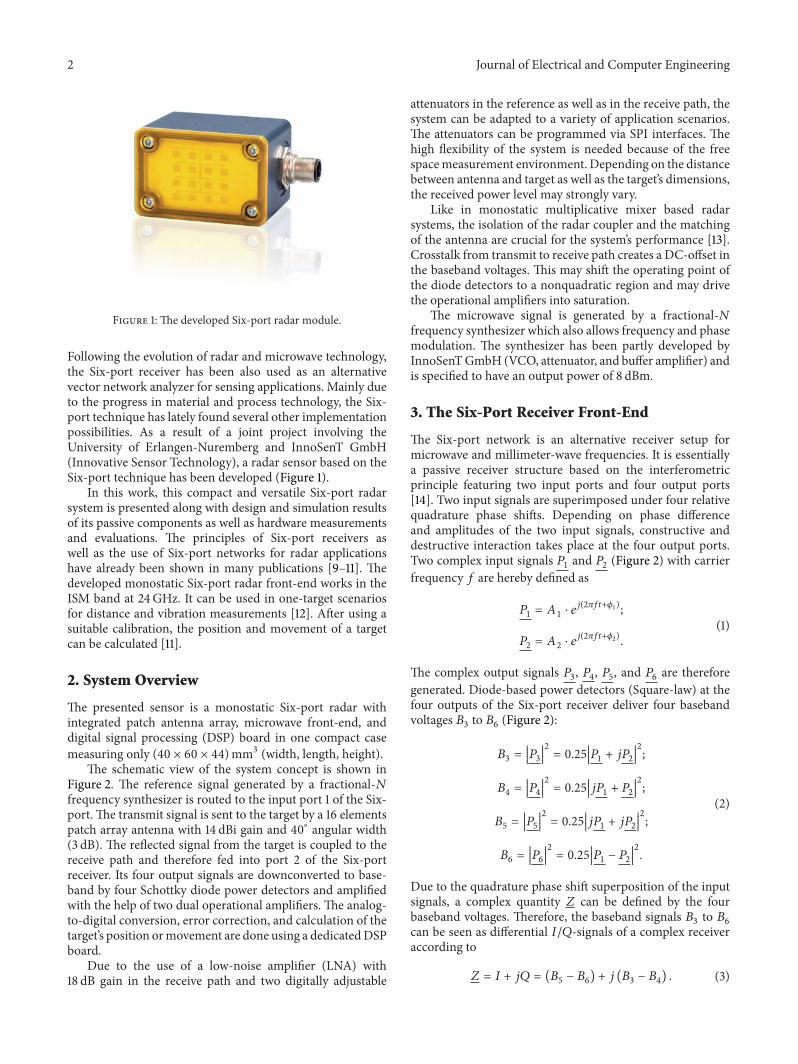
The schematic view of the system concept is shown inFigure 2 The reference signal generated by a fractional-119873frequency synthesizer is routed to the input port 1 of the Six-port The transmit signal is sent to the target by a 16 elementspatch array antenna with 14 dBi gain and 40∘ angular width(3 dB) The reflected signal from the target is coupled to thereceive path and therefore fed into port 2 of the Six-portreceiver Its four output signals are downconverted to base-band by four Schottky diode power detectors and amplifiedwith the help of two dual operational amplifiers The analog-to-digital conversion error correction and calculation of thetargetrsquos position ormovement are done using a dedicatedDSPboard
Due to the use of a low-noise amplifier (LNA) with18 dB gain in the receive path and two digitally adjustable
attenuators in the reference as well as in the receive path thesystem can be adapted to a variety of application scenariosThe attenuators can be programmed via SPI interfaces Thehigh flexibility of the system is needed because of the freespacemeasurement environment Depending on the distancebetween antenna and target as well as the targetrsquos dimensionsthe received power level may strongly vary
Like in monostatic multiplicative mixer based radarsystems the isolation of the radar coupler and the matchingof the antenna are crucial for the systemrsquos performance [13]Crosstalk from transmit to receive path creates a DC-offset inthe baseband voltages This may shift the operating point ofthe diode detectors to a nonquadratic region and may drivethe operational amplifiers into saturation
The microwave signal is generated by a fractional-119873frequency synthesizer which also allows frequency and phasemodulation The synthesizer has been partly developed byInnoSenTGmbH (VCO attenuator and buffer amplifier) andis specified to have an output power of 8 dBm
3 The Six-Port Receiver Front-End
The Six-port network is an alternative receiver setup formicrowave and millimeter-wave frequencies It is essentiallya passive receiver structure based on the interferometricprinciple featuring two input ports and four output ports[14] Two input signals are superimposed under four relativequadrature phase shifts Depending on phase differenceand amplitudes of the two input signals constructive anddestructive interaction takes place at the four output portsTwo complex input signals 119875
1and 119875
2(Figure 2) with carrier
frequency 119891 are hereby defined as
1198751= 1198601sdot 119890119895(2120587119891119905+120601
1)
1198752= 1198602sdot 119890119895(2120587119891119905+120601
2)
(1)
The complex output signals 1198753 1198754 1198755 and 119875
6are therefore
generated Diode-based power detectors (Square-law) at thefour outputs of the Six-port receiver deliver four basebandvoltages 119861
3to 1198616(Figure 2)
1198613=
100381610038161003816100381610038161198753
10038161003816100381610038161003816
2
= 025
100381610038161003816100381610038161198751+ 1198951198752
10038161003816100381610038161003816
2
1198614=
100381610038161003816100381610038161198754
10038161003816100381610038161003816
2
= 025
100381610038161003816100381610038161198951198751+ 1198752
10038161003816100381610038161003816
2
1198615=
100381610038161003816100381610038161198755
10038161003816100381610038161003816
2
= 025
100381610038161003816100381610038161198951198751+ 1198951198752
10038161003816100381610038161003816
2
1198616=
100381610038161003816100381610038161198756
10038161003816100381610038161003816
2
= 025
100381610038161003816100381610038161198751minus 1198752
10038161003816100381610038161003816
2
(2)
Due to the quadrature phase shift superposition of the inputsignals a complex quantity 119885 can be defined by the fourbaseband voltages Therefore the baseband signals 119861
3to 1198616
can be seen as differential 119868119876-signals of a complex receiveraccording to
119885 = 119868 + 119895119876 = (1198615minus 1198616) + 119895 (119861
3minus 1198614) (3)
Journal of Electrical and Computer Engineering 3
Six-port Digital
attenuatorDigital
attenuatorLNA
PLL VCO30 MHz
Radarcoupler
Antenna
DSP
P2
P1
Synthesizer 24ndash2425 GHz
B3 6 P3 6
Figure 2 Schematical view of the radar front-end
P 2
P 3
P 1
P 4
P 6 P 5
50 Ω
Port 2
Port 3
Port 1
Port 4
Port 6 Port 5
50 Ω
100 Ω
Figure 3 Schematical view and layout of the Six-port network
Finally the argument of 119885 can be calculated delivering thephase shift between the two input signals of the Six-port
Δ120590 = 1206011minus 1206012= arg 119885 (4)
When using the Six-port as a receiver for radar applicationsthe phase shift Δ120590 comprises the distance information andcan be directly renormalized when the wavelength of thesignal is known [11]
119889 = 120582
Δ120590
2 sdot 2120587
(5)
Since the measurement relies on a phase difference evalu-ation an ambiguity in the measurement will occur if thedistance to be measured is greater than half the wavelengthof the radar signal Nevertheless as described in Section 4by using appropriate modulation schemes the ambiguityin phase can be resolved to determine a unique distancemeasurement to the target
In Figure 3 the circuit schematic and hardware imple-mentation inmicrostrip technology of the developed Six-portnetwork can be seen A Wilkinson power divider and threequadrature hybrid couplers also called branchline couplersgenerate the mentioned phase shifts
4 Digital Signal Processing
After some analog signal conditioning procedures in base-band the output signals from the Six-port receiver are sam-pled by synchronously triggered analog-to-digital converters(ADC) and evaluated by a microcontroller that manages thecomplete sensor module The sampling rate is set to 250 kHzand the resolution of the ADCs is 12-bit The calculateddistance information is made available through an RS-232parallel port in a 32-bit floating point format
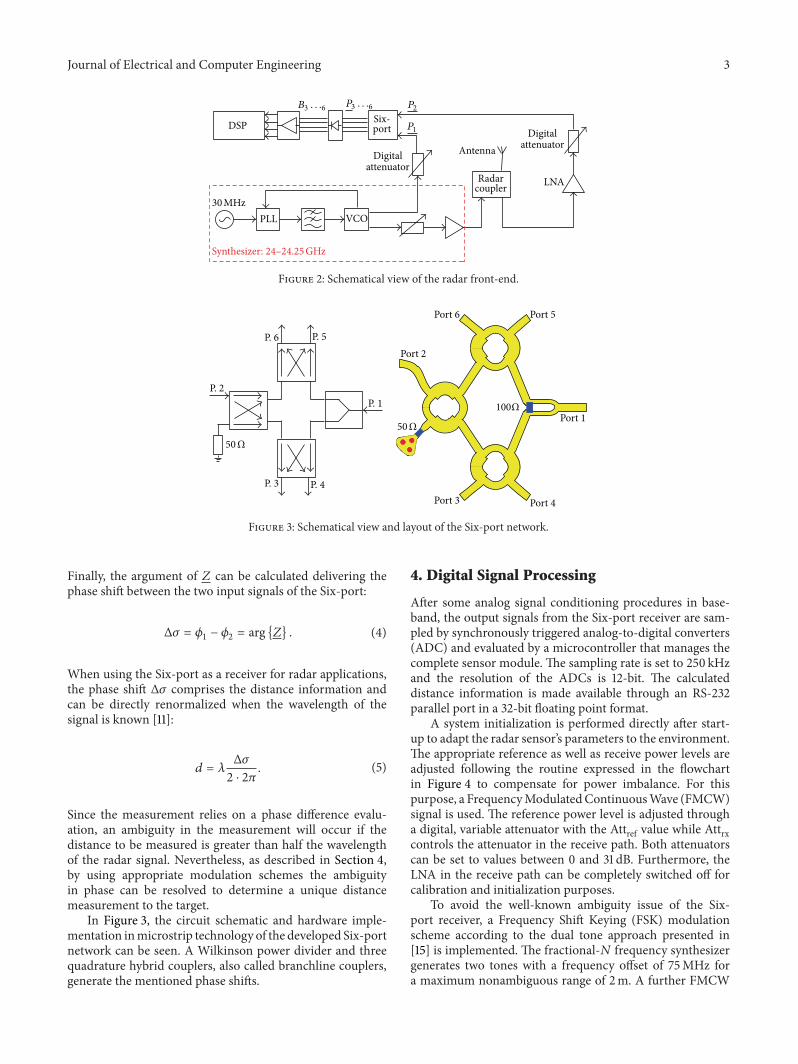
A system initialization is performed directly after start-up to adapt the radar sensorrsquos parameters to the environmentThe appropriate reference as well as receive power levels areadjusted following the routine expressed in the flowchartin Figure 4 to compensate for power imbalance For thispurpose a FrequencyModulatedContinuousWave (FMCW)signal is used The reference power level is adjusted througha digital variable attenuator with the Attref value while Attrxcontrols the attenuator in the receive path Both attenuatorscan be set to values between 0 and 31 dB Furthermore theLNA in the receive path can be completely switched off forcalibration and initialization purposes
To avoid the well-known ambiguity issue of the Six-port receiver a Frequency Shift Keying (FSK) modulationscheme according to the dual tone approach presented in[15] is implemented The fractional-119873 frequency synthesizergenerates two tones with a frequency offset of 75MHz fora maximum nonambiguous range of 2m A further FMCW
4 Journal of Electrical and Computer Engineering
Min referenceattenuationAttref = 0
Frequencymodulation
250 MHz slope
Frequencymodulation
250 MHz slope
Clippingerror
Clippingerror
Attref ++ Attreflt 31
Enablereceive LNAMin receiveattenuation
Attrx = 0
Finished
Attrx ++ Attrxlt 31
Initstart
Disablereceive LNAMax receiveattenuationAttrx = 31
Yes
Yes
Yes
YesFailed
Failed
No
No
No
No
Figure 4 Initialization diagram
modulation scheme can be implemented to evaluate speedand range of a target as described in [16]
5 Simulation and Analysis
The simulation results of the passive microwave componentsare shown in this chapter The results were obtained with the3D electromagnetic field simulator CST Microwave Studiousing the Frequency Domain Solver For more details aboutthe theory of the basic circuits (ie Wilkinson power dividerquadrature hybrid coupler) the reader may refer to [17] andfor the Six-port network to [10]
51 Quadrature Hybrid Coupler The layout for a roundquadrature hybrid coupler at 24GHz is shown in Figure 6(a)The incident wave is fed to port 1 port 4 is isolated and port2 and 3 are the output ports The transmission line lengthbetween the ports is a quarter of the wavelength A roundlayout has been chosen because the geometrical 90∘ angle
Frequency (GHz)
S11S41
20 22 24 26 28minus50
minus40
minus30
minus20
minus10
S-p
aram
eter
(dB)
Figure 5 Simulated 11987811and 119878
41of the quadrature hybrid coupler
between port 1 and 4 as illustrated in Figure 6(a) leads toa higher isolation which is a crucial parameter for radarcouplers
Figure 5 shows the simulated input reflection coefficientat port 1 (119878
11(dB)) and the isolation between port 1 and 4
(11987841(dB)) The hybrid coupler is well matched within the
entire bandwidth (minus38 dB at 24GHz and 2425GHz andminus45 dB at the center frequency) The isolation is higher than33 dB in the frequency band of interest Due to the highisolation values the coupler is also used as radar coupler withone port being terminated
The simulation results for the transmission are presentedin Figure 7 For an ideal hybrid coupler the transmission losswould be minus3 dB and the phase difference would be 90∘ For24GHz the required phase difference is reached Howeverthe transmission loss between port 1 and 3 is minus32 dBand minus37 dB between port 1 and 2 although the path length toport 3 is longer than to port 2 A reason for this unexpecteddifference may be the geometrical 90∘ angle between port 1and 2
52 Wilkinson Power Divider The layout of the Wilkinsonpower divider is shown in Figure 6(b) It has been optimizedto have a good matching at all ports and a high isolationbetween port 2 and 3 for 24GHz According to the simulationresults shown in Figure 8 matching of port 1 and 2 as wellas transmission between port 2 and 3 are below minus20 dBThis is necessary to avoid standing waves inside the Six-portnetwork and coupling between the four Schottky diode powerdetectors
53 Six-Port Network In Section 3 it has been demonstratedby (2) that the Six-port receiver relies on four quadraturephase shifts In the Six-port network used in this work thesephase shifts are generated by three branchline couplers andone Wilkinson power divider The schematic and the layoutof the resulting network are presented in Figure 3
Journal of Electrical and Computer Engineering 5
Port 1
Port 2
Port 4
Port 315 mm
90∘
(a)
Port 1
Port 2 Port 3100 Ω
12058204radic2Z0
(b)
Figure 6 Layout of (a) 90∘ hybrid coupler and (b) Wilkinson power divider
20 22 24 26 28minus55
minus5
minus45
minus4
minus35
minus3
Frequency (GHz)
S21S31
S-p
aram
eter
(dB)
Figure 7 Simulated transmission coefficient of coupler
20 22 24 26 28minus45
minus40
minus35
minus30
minus25
minus20
minus15
minus10
minus5
0
Frequency (GHz)
S11S21
S23S22
S-p
aram
eter
(dB)
Figure 8 Simulated scattering parameters of power divider
20 22 24 26 28minus11
minus10
minus9
minus8
minus7
minus6
Frequency (GHz)
S31S41
S51S61
S-p
aram
eter
(dB)
Figure 9 Six-port simulated transmission from port 1 to the outputports
3D field simulation shows that the power imbalance of thetransmission from the input to the output ports is less than2 dB (Figures 9 and 10) and the relative phase shiftsmatch 90∘with only 4∘ error (Figure 11) The reflection coefficient of theinput ports and the isolation between them are below minus20 dBfor 24125GHz plusmn 125MHz
6 Applications Overview
61 Distance Measurement High-resolution distance mea-surements with short and long range positioning are impor-tant for a large number of sensing applications [18] Theradar module implements a fractional-119873 frequency syn-thesizer enabling different modulation schemes to performnonambiguous distancemeasurementsThe Six-port receiversuffers from ambiguity issues if distances of more than halfa wavelength are measured A solution to this problem isto use a two or more tone FSK modulation of the carrier
6 Journal of Electrical and Computer Engineering
20 22 24 26 28minus11
minus10
minus9
minus8
minus7
minus6
Frequency (GHz)
S-p
aram
eter
(dB)
S32S42
S52S62
Figure 10 Six-port simulated transmission from port 2 to theoutput ports
20 22 24 26 280
50
100
150
200
250
300
350
93
274
181
0
Frequency (GHz)
Phas
e diff
eren
ce(∘)
Port 3Port 4
Port 5Port 6
Figure 11 Simulated normalized phase difference at the output portsof the Six-port network (reference port 6 is set to 0∘)
frequency and comparing the observed phase differences ofthese signals to each other This allows to measure distancesof several wavelengths with subwavelength accuracy andultralow tolerances
62 Vibration Measurement Particularly interesting is theanalysis of small displacements of an observed target forinstance vibration monitoring [2] Since the Six-port basedradar sensor provides very high accuracy distance detectioneven the smallest vibrations (ie distance variations of thetarget surface with respect to the sensor) can be accuratelydetected Performing a frequency domain analysis a spectro-gram of the targetrsquos mechanical vibrations can be obtained
This leads to relevant information about the working condi-tions of diverse industrial machineryThe sensor can be usedfor modal analysis in order to measure the dynamic responseof mechanical structures and the different vibration modesBy observing for instance a rotating turbine thus illuminatingthe complete machine with the Six-port radar the mainmechanical resonances can be recorded and monitoredIn case of a mechanical malfunction or degradation forinstance a wearing of the axis bearings minor changes inthe mechanical resonances will occur Such effects can bethereforemonitoredwithout even applying sensors directly tothe machine In other words a contactless vibration analysisfor diverse industrial machines can be easily performed Asthe reconstruction algorithms feature low complexity and canbe calculated very fast the maximum detectable vibrationfrequency is only limited by the sampling frequency of theanalog-digital interface
63 Contactless Heartbeat and Respiration Monitoring Formedical applications the heartbeat and breathing activitiesaffect the phase of the reflected signal which is comparedwith the reference signal source in the radar device [11] Aradar signal is sent towards the person under test to observeminor mechanical movements of the patientrsquos body Thesemovements are caused by the respiration as well as heartbeatand can be tracked by analyzing the phase modulation ofthe backscattered signal The patients respiration will resultin a significant and periodic extension of the torso whichis in the range of several millimeters Additionally theheartbeat will be superimposed to this movement which isassumed to be in the submillimeter range These periodicmovements and vibrations can subsequently be detected bysignal postprocessing
7 Measurements
The passive RF subcomponents have been fabricated on atest PCB based on the Rogers RO4835 substrate materialand characterized with a vector network analyzerThe resultsare shown in Sections 71 and 72 Furthermore evaluationmeasurements of the complete system are presented inSection 74 A photo of the RF front-end is shown in Figure 12
71 Quadrature Hybrid Coupler The properties of the radarcoupler are crucial for the performance of the overall sys-tem Therefore measurement results for this component arehereby presented As illustrated in Figure 13 the isolationbetween port 1 and 4 (119878
41(dB)) of the proposed coupler
between 24 and 2425GHz is higher than 25 dB whereasthe isolation between port 2 and 3 (119878
32(dB)) is higher than
30 dB Since the coupler has been designed to be symmetricalthe deviation between 119878
41and 119878
32results from fabrication
and measurement inaccuracies The power imbalance in thetransmission from port 1 to ports 2 and 3 is 02 dB only(Figure 14) The generated phase difference between ports 2and 3 varies between 881∘ and 873∘ which leads to the fourquadrature phase shifts of the Six-port network The idealphase shift is 90∘
Journal of Electrical and Computer Engineering 7
57 mm
37 m
m
Figure 12 Photo of the radar front-end
20 22 24 26minus45
minus40
minus35
minus30
minus25
minus20
minus15
minus10
Frequency (GHz)
S-p
aram
eter
(dB)
S41S32
Figure 13 Measured 11987841and 119878
32of the hybrid coupler
20 22 24 26minus8
minus75
minus7
minus65
minus6
minus55
minus5
Frequency (GHz)
S-p
aram
eter
(dB)
S21S31
Figure 14 Measured transmission coefficient of the hybrid coupler
Table 1 Normalized phase difference at the output ports
Frequency 24GHz 2425GHz IdealPort 3 922∘ 913∘ 90∘
Port 4 2721∘ 2709∘ 270∘
Port 5 1813∘ 1795∘ 180∘
20 22 24 260
50
100
150
200
250
300
350
92
272
181
0
Frequency (GHz)
Phas
e diff
eren
ce(∘)
Port 3Port 4
Port 5Port 6
Figure 15 Measured normalized phase difference at the outputports of the Six-port network (reference port 6 is set to 0∘)
72 Six-Port Network Measurement results in Figure 15 andTable 1 show that the four quadrature phase shifts between24 and 2425GHz can be obtained with only 2∘ deviationwhich is due to the optimal phase shift performance of thequadrature hybrid coupler
Moreover the designed Six-port network features highisolation between input ports 1 and 2 (minus30 dB) The returnloss at the input ports is lower thanminus15 dB while at the outputports 3 4 5 and 6 it is lower than minus20 dB Furthermorethe power imbalance at the output ports is less than 17 dBas shown in Figures 16 and 17
73 Theoretical Distance Accuracy Limits A circuit sim-ulation with Agilent Advanced Design System has beenperformed in order to estimate the theoretical accuracy ofthe radar front-end due to the imperfections of the Six-port network and the quadrature hybrid coupler used asradar coupler The measured 119878-parameters of the couplerresult in a maximum phase shift error Δ120590err = plusmn115
∘
and therefore in a maximum distance measurement error119889err = plusmn200 120583m System simulation with the measured Six-port network performance and apart from that an ideal RFfront-end results in Δ120590err = plusmn75
∘ and 119889err = plusmn130 120583m Usingthe measured 119878-parameters of Six-port network and couplerleads to a maximum phase shift error Δ120590err = plusmn12
∘ and amaximum error of the measured distance 119889err = plusmn210 120583m
8 Journal of Electrical and Computer Engineering
20 22 24 26minus13
minus12
minus11
minus10
minus9
minus8
Frequency (GHz)
S-p
aram
eter
(dB)
S31S41
S51S61
Figure 16 Six-port measured transmission from port 1 to theoutput ports
20 22 24 26minus13
minus12
minus11
minus10
minus9
minus8
Frequency (GHz)
S-p
aram
eter
(dB)
S32S42
S52S62
Figure 17 Six-port measured transmission from port 2 to theoutput ports
These measurement errors have a characteristic sinu-soidal shape Consequently they can be compensated by asuitable calibration The same holds for measurement errorsdue to additional static targets for example in an industrialenvironment These have a periodicity of 1205824 and can becompensated
74 Distance Measurements The Six-port radar system hasbeen tested by sweeping the position of a corner reflectorused as a target with the help of a high precision computercontrolled linear stage The target has been placed at adistance of 17m and shifted by 150mm towards the radarwith steps of 100120583mThe reference for the positioning system
0 25 50 75 100 125 150minus08
minus06
minus04
minus02
0
02
04
06
08
Distance (mm)
Erro
r (m
m)
Data 1Data 2Data 3Data 4Data 5
Data 6Data 7Data 8Data 9Data 10
Figure 18 Absolute measurement error
is the optical encoder of the linear stage which features aresolution of 05 120583mThemeasurement has been repeated tentimes in one hour time frame The targetrsquos displacement hasbeen calculated from the measured phase with (5)
In order to get a more detailed view of the results theabsolutemeasurement error has been calculated and is shownin Figure 18 for all datasets A constant drift of the offset anda similar periodic behavior of all datasets can be observedNevertheless this error can be compensated as it is equalfor all measurements and therefore characteristic for thesystem For this reason after a calibration based on onedataset the relative error has been calculated and is presentedin Figure 19 The variation of the relative error betweenminimum and maximum is due to a constant and slow driftbetween the datasets and is probably caused by a systemrsquostemperature change within the measurement time frame ofone hour
In order to evaluate the systemrsquos accuracy independentlyfrom this constant drift over time 10000 measurementvalues have been recorded with an interval of 10ms resultingin a total measurement time frame of 100 s The standarddeviation of themeasured position expressed in relative resultfrequency is plotted in Figure 20 838 of the measuredposition values lies within plusmn20120583maround the actual positionvalue 996 lies within plusmn40120583m
8 Conclusion
A compact versatile radar module based on the Six-porttechnique working in the ISM band at 24GHz has beenpresented The monostatic radar system measures only (40 times60 times 44)mm3 and features a high integration of all
Journal of Electrical and Computer Engineering 9
0 25 50 75 100 125 150minus08
minus06
minus04
minus02
0
02
04
06
08
Distance (mm)
Relat
ive e
rror
(mm
)
MeanMinMax
Figure 19 Relative measurement error
minus006 minus004 minus002 0 002 004 0060
05
1
15
2
25
3
35
Measured position (mm)
Relat
ive f
requ
ency
()
Figure 20 Standard deviation of measurement results
subcomponents such as RF source patch antenna array Six-port based receiver baseband circuitry and digital signalprocessing in one single housing Simulation results of thepassive microwave components have been validated withmeasurements showing good design performance An overallevaluation of the radar system demonstrates a high precisionin the micrometer range (plusmn40120583m) and a maximum relativeerror of plusmn400120583mdue to a slow drift over timeThese positiveresults are due to the excellent phase discrimination proper-ties of the Six-port receiver The proposed system is thereforesuitable for several industrial andmedical applications wherehighmeasurement accuracy is required such as displacementand vibration measurements as well as remote breath andheartbeat monitoring
Acknowledgments
The authors would like to thank Holger Ebert Thomas Poppand other engineers from the RampD department Industrial
Division at InnoSenT GmbH for the technical support andfor the production of the sensors modules in the companyrsquosmanufacturing facilities
References
[1] F Barbon G Vinci S Lindner R Weigel and A Koelpin ldquoAsix-port interferometer based micrometer-accuracy displace-ment and vibration measurement radarrdquo in Proceedings of theIEEE MTT-S International Microwave Symposium Digest (MTTrsquo12) pp 1ndash3 2012
[2] G Vinci S Lindner S Mann et al ldquoSix-port microwave inter-ferometer radar for mechanical vibration analysisrdquo in Proceed-ings of the European Radar Conference Nuremberg Germany2013
[3] A Stelzer ldquoA microwave position sensor with submillimeteraccuracyrdquo IEEE Transactions on Microwave Theory and Tech-niques vol 47 no 12 pp 2621ndash2624 1999
[4] S Ayhan M Pauli T Kayser S Scherr and T Zwick ldquoFMCWradar systemwith additional phase evaluation for high accuracyrange detectionrdquo in Proceedings of the 8th European RadarConference (EuRAD rsquo11) pp 117ndash120 October 2011
[5] G Vinci S Lindner F Barbon et al ldquo24 GHz six-port medicalradar for contactless respiration detection and heartbeat mon-itoringrdquo in Proceedings of the 9th European Radar Conference(EuRAD rsquo12) pp 75ndash78 2012
[6] A Koelpin G Vinci B Laemmle S Lindner F Barbon and RWeigel ldquoSix-port technology for traffic safetyrdquo IEEE MicrowaveMagazine vol 13 no 3 pp 118ndash127 2012
[7] G Vinci F Barbon B Laemmle R Weigel and A Koelpin ldquoAwiderange 77 GHzDirection of Arrival detector with integrateddual six-port receiverrdquo in Proceedings of the InternationalMicrowave Symposium (IMS rsquo12) Montreal Canada 2012
[8] C A Hoer ldquoUsing six-port and eight-port junctions tomeasureactive andpassive circuit parametersrdquoNBSTechNote 673 1975
[9] G F Engen ldquoThe six-port reflectometer an alternative networkanalyzerrdquo IEEE Transactions on Microwave Theory and Tech-niques vol 25 no 12 pp 1075ndash1080 1977
[10] F M Ghannouchi and A MohammadiThe Six-Port Techniquewith Microwave and Wireless Applications Artech House 2009
[11] G Vinci S Lindner F Barbon et al ldquoSix-port radar sensor forremote respiration rate and heartbeat vital-sign monitoringrdquoIEEE Transactions onMicrowaveTheory and Techniques vol 61no 5 pp 2093ndash2100 2013
[12] A Koelpin G Vinci F Barbon S Lindner R Weigel and GFischer ldquoThe six-port technology a low-cost concept for preciseposition measurementsrdquo in Proceedings of the InternationalMulti-Conference on Systems Signals and Devices (SSD rsquo12)Chemnitz Germany 2012
[13] M Jahn C Wagner and A Stelzer ldquoDC-offset compensa-tion concept for monostatic FMCW radar transceiversrdquo IEEEMicrowave and Wireless Components Letters vol 20 no 9 pp525ndash527 2010
[14] A Koelpin G Vinci B Laemmle D Kissinger and R WeigelldquoThe six-port in modern societyrdquo IEEE Microwave Magazinevol 11 no 7 pp S35ndashS43 2010
[15] S Lindner G Vinci F Barbon S Mann R Weigel and AKoelpin ldquoDual tone approach for unambiguous six-port basedinterferometric distance measurementsrdquo in Proceedings of theInternational Microwave Symposium (IMS rsquo13) Seattle WashUSA 2013
10 Journal of Electrical and Computer Engineering
[16] B Bonkari E Moldovan S Affes K Wu R G Bosisio and SO Tatu ldquoSix-port FMCWcollision avoidance radar sensor con-figurationsrdquo in Proceedings of the IEEE Canadian Conference onElectrical and Computer Engineering (CCECE rsquo08) pp 305ndash308May 2008
[17] DM PozarMicrowave Engineering JohnWiley and Sons 2005[18] P Pahl T Kayser M Pauli and T Zwick ldquoEvaluation of a high
accuracy range detection algorithm for FMCWPhase radarsystemsrdquo in Proceedings of the 7th European Radar Conference(EuRAD rsquo10) pp 160ndash163 October 2010
International Journal of
AerospaceEngineeringHindawi Publishing Corporationhttpwwwhindawicom Volume 2014
RoboticsJournal of
Hindawi Publishing Corporationhttpwwwhindawicom Volume 2014
Hindawi Publishing Corporationhttpwwwhindawicom Volume 2014
Active and Passive Electronic Components
Control Scienceand Engineering
Journal of
Hindawi Publishing Corporationhttpwwwhindawicom Volume 2014
International Journal of
RotatingMachinery
Hindawi Publishing Corporationhttpwwwhindawicom Volume 2014
Hindawi Publishing Corporation httpwwwhindawicom
Journal ofEngineeringVolume 2014
Submit your manuscripts athttpwwwhindawicom
VLSI Design
Hindawi Publishing Corporationhttpwwwhindawicom Volume 2014
Hindawi Publishing Corporationhttpwwwhindawicom Volume 2014
Shock and Vibration
Hindawi Publishing Corporationhttpwwwhindawicom Volume 2014
Civil EngineeringAdvances in
Acoustics and VibrationAdvances in
Hindawi Publishing Corporationhttpwwwhindawicom Volume 2014
Hindawi Publishing Corporationhttpwwwhindawicom Volume 2014
Electrical and Computer Engineering
Journal of
Advances inOptoElectronics
Hindawi Publishing Corporation httpwwwhindawicom
Volume 2014
The Scientific World JournalHindawi Publishing Corporation httpwwwhindawicom Volume 2014
SensorsJournal of
Hindawi Publishing Corporationhttpwwwhindawicom Volume 2014
Modelling amp Simulation in EngineeringHindawi Publishing Corporation httpwwwhindawicom Volume 2014
Hindawi Publishing Corporationhttpwwwhindawicom Volume 2014
Chemical EngineeringInternational Journal of Antennas and
Propagation
International Journal of
Hindawi Publishing Corporationhttpwwwhindawicom Volume 2014
Hindawi Publishing Corporationhttpwwwhindawicom Volume 2014
Navigation and Observation
International Journal of
Hindawi Publishing Corporationhttpwwwhindawicom Volume 2014
DistributedSensor Networks
International Journal of
2 Journal of Electrical and Computer Engineering
Figure 1 The developed Six-port radar module
Following the evolution of radar and microwave technologythe Six-port receiver has been also used as an alternativevector network analyzer for sensing applications Mainly dueto the progress in material and process technology the Six-port technique has lately found several other implementationpossibilities As a result of a joint project involving theUniversity of Erlangen-Nuremberg and InnoSenT GmbH(Innovative Sensor Technology) a radar sensor based on theSix-port technique has been developed (Figure 1)
In this work this compact and versatile Six-port radarsystem is presented along with design and simulation resultsof its passive components as well as hardware measurementsand evaluations The principles of Six-port receivers aswell as the use of Six-port networks for radar applicationshave already been shown in many publications [9ndash11] Thedeveloped monostatic Six-port radar front-end works in theISM band at 24GHz It can be used in one-target scenariosfor distance and vibration measurements [12] After using asuitable calibration the position and movement of a targetcan be calculated [11]
2 System Overview
The presented sensor is a monostatic Six-port radar withintegrated patch antenna array microwave front-end anddigital signal processing (DSP) board in one compact casemeasuring only (40 times 60 times 44)mm3 (width length height)
The schematic view of the system concept is shown inFigure 2 The reference signal generated by a fractional-119873frequency synthesizer is routed to the input port 1 of the Six-port The transmit signal is sent to the target by a 16 elementspatch array antenna with 14 dBi gain and 40∘ angular width(3 dB) The reflected signal from the target is coupled to thereceive path and therefore fed into port 2 of the Six-portreceiver Its four output signals are downconverted to base-band by four Schottky diode power detectors and amplifiedwith the help of two dual operational amplifiers The analog-to-digital conversion error correction and calculation of thetargetrsquos position ormovement are done using a dedicatedDSPboard
Due to the use of a low-noise amplifier (LNA) with18 dB gain in the receive path and two digitally adjustable
attenuators in the reference as well as in the receive path thesystem can be adapted to a variety of application scenariosThe attenuators can be programmed via SPI interfaces Thehigh flexibility of the system is needed because of the freespacemeasurement environment Depending on the distancebetween antenna and target as well as the targetrsquos dimensionsthe received power level may strongly vary
Like in monostatic multiplicative mixer based radarsystems the isolation of the radar coupler and the matchingof the antenna are crucial for the systemrsquos performance [13]Crosstalk from transmit to receive path creates a DC-offset inthe baseband voltages This may shift the operating point ofthe diode detectors to a nonquadratic region and may drivethe operational amplifiers into saturation
The microwave signal is generated by a fractional-119873frequency synthesizer which also allows frequency and phasemodulation The synthesizer has been partly developed byInnoSenTGmbH (VCO attenuator and buffer amplifier) andis specified to have an output power of 8 dBm
3 The Six-Port Receiver Front-End
The Six-port network is an alternative receiver setup formicrowave and millimeter-wave frequencies It is essentiallya passive receiver structure based on the interferometricprinciple featuring two input ports and four output ports[14] Two input signals are superimposed under four relativequadrature phase shifts Depending on phase differenceand amplitudes of the two input signals constructive anddestructive interaction takes place at the four output portsTwo complex input signals 119875
1and 119875
2(Figure 2) with carrier
frequency 119891 are hereby defined as
1198751= 1198601sdot 119890119895(2120587119891119905+120601
1)
1198752= 1198602sdot 119890119895(2120587119891119905+120601
2)
(1)
The complex output signals 1198753 1198754 1198755 and 119875
6are therefore
generated Diode-based power detectors (Square-law) at thefour outputs of the Six-port receiver deliver four basebandvoltages 119861
3to 1198616(Figure 2)
1198613=
100381610038161003816100381610038161198753
10038161003816100381610038161003816
2
= 025
100381610038161003816100381610038161198751+ 1198951198752
10038161003816100381610038161003816
2
1198614=
100381610038161003816100381610038161198754
10038161003816100381610038161003816
2
= 025
100381610038161003816100381610038161198951198751+ 1198752
10038161003816100381610038161003816
2
1198615=
100381610038161003816100381610038161198755
10038161003816100381610038161003816
2
= 025
100381610038161003816100381610038161198951198751+ 1198951198752
10038161003816100381610038161003816
2
1198616=
100381610038161003816100381610038161198756
10038161003816100381610038161003816
2
= 025
100381610038161003816100381610038161198751minus 1198752
10038161003816100381610038161003816
2
(2)
Due to the quadrature phase shift superposition of the inputsignals a complex quantity 119885 can be defined by the fourbaseband voltages Therefore the baseband signals 119861
3to 1198616
can be seen as differential 119868119876-signals of a complex receiveraccording to
119885 = 119868 + 119895119876 = (1198615minus 1198616) + 119895 (119861
3minus 1198614) (3)
Journal of Electrical and Computer Engineering 3
Six-port Digital
attenuatorDigital
attenuatorLNA
PLL VCO30 MHz
Radarcoupler
Antenna
DSP
P2
P1
Synthesizer 24ndash2425 GHz
B3 6 P3 6
Figure 2 Schematical view of the radar front-end
P 2
P 3
P 1
P 4
P 6 P 5
50 Ω
Port 2
Port 3
Port 1
Port 4
Port 6 Port 5
50 Ω
100 Ω
Figure 3 Schematical view and layout of the Six-port network
Finally the argument of 119885 can be calculated delivering thephase shift between the two input signals of the Six-port
Δ120590 = 1206011minus 1206012= arg 119885 (4)
When using the Six-port as a receiver for radar applicationsthe phase shift Δ120590 comprises the distance information andcan be directly renormalized when the wavelength of thesignal is known [11]
119889 = 120582
Δ120590
2 sdot 2120587
(5)
Since the measurement relies on a phase difference evalu-ation an ambiguity in the measurement will occur if thedistance to be measured is greater than half the wavelengthof the radar signal Nevertheless as described in Section 4by using appropriate modulation schemes the ambiguityin phase can be resolved to determine a unique distancemeasurement to the target
In Figure 3 the circuit schematic and hardware imple-mentation inmicrostrip technology of the developed Six-portnetwork can be seen A Wilkinson power divider and threequadrature hybrid couplers also called branchline couplersgenerate the mentioned phase shifts
4 Digital Signal Processing
After some analog signal conditioning procedures in base-band the output signals from the Six-port receiver are sam-pled by synchronously triggered analog-to-digital converters(ADC) and evaluated by a microcontroller that manages thecomplete sensor module The sampling rate is set to 250 kHzand the resolution of the ADCs is 12-bit The calculateddistance information is made available through an RS-232parallel port in a 32-bit floating point format
A system initialization is performed directly after start-up to adapt the radar sensorrsquos parameters to the environmentThe appropriate reference as well as receive power levels areadjusted following the routine expressed in the flowchartin Figure 4 to compensate for power imbalance For thispurpose a FrequencyModulatedContinuousWave (FMCW)signal is used The reference power level is adjusted througha digital variable attenuator with the Attref value while Attrxcontrols the attenuator in the receive path Both attenuatorscan be set to values between 0 and 31 dB Furthermore theLNA in the receive path can be completely switched off forcalibration and initialization purposes
To avoid the well-known ambiguity issue of the Six-port receiver a Frequency Shift Keying (FSK) modulationscheme according to the dual tone approach presented in[15] is implemented The fractional-119873 frequency synthesizergenerates two tones with a frequency offset of 75MHz fora maximum nonambiguous range of 2m A further FMCW
4 Journal of Electrical and Computer Engineering
Min referenceattenuationAttref = 0
Frequencymodulation
250 MHz slope
Frequencymodulation
250 MHz slope
Clippingerror
Clippingerror
Attref ++ Attreflt 31
Enablereceive LNAMin receiveattenuation
Attrx = 0
Finished
Attrx ++ Attrxlt 31
Initstart
Disablereceive LNAMax receiveattenuationAttrx = 31
Yes
Yes
Yes
YesFailed
Failed
No
No
No
No
Figure 4 Initialization diagram
modulation scheme can be implemented to evaluate speedand range of a target as described in [16]
5 Simulation and Analysis
The simulation results of the passive microwave componentsare shown in this chapter The results were obtained with the3D electromagnetic field simulator CST Microwave Studiousing the Frequency Domain Solver For more details aboutthe theory of the basic circuits (ie Wilkinson power dividerquadrature hybrid coupler) the reader may refer to [17] andfor the Six-port network to [10]
51 Quadrature Hybrid Coupler The layout for a roundquadrature hybrid coupler at 24GHz is shown in Figure 6(a)The incident wave is fed to port 1 port 4 is isolated and port2 and 3 are the output ports The transmission line lengthbetween the ports is a quarter of the wavelength A roundlayout has been chosen because the geometrical 90∘ angle
Frequency (GHz)
S11S41
20 22 24 26 28minus50
minus40
minus30
minus20
minus10
S-p
aram
eter
(dB)
Figure 5 Simulated 11987811and 119878
41of the quadrature hybrid coupler
between port 1 and 4 as illustrated in Figure 6(a) leads toa higher isolation which is a crucial parameter for radarcouplers
Figure 5 shows the simulated input reflection coefficientat port 1 (119878
11(dB)) and the isolation between port 1 and 4
(11987841(dB)) The hybrid coupler is well matched within the
entire bandwidth (minus38 dB at 24GHz and 2425GHz andminus45 dB at the center frequency) The isolation is higher than33 dB in the frequency band of interest Due to the highisolation values the coupler is also used as radar coupler withone port being terminated
The simulation results for the transmission are presentedin Figure 7 For an ideal hybrid coupler the transmission losswould be minus3 dB and the phase difference would be 90∘ For24GHz the required phase difference is reached Howeverthe transmission loss between port 1 and 3 is minus32 dBand minus37 dB between port 1 and 2 although the path length toport 3 is longer than to port 2 A reason for this unexpecteddifference may be the geometrical 90∘ angle between port 1and 2
52 Wilkinson Power Divider The layout of the Wilkinsonpower divider is shown in Figure 6(b) It has been optimizedto have a good matching at all ports and a high isolationbetween port 2 and 3 for 24GHz According to the simulationresults shown in Figure 8 matching of port 1 and 2 as wellas transmission between port 2 and 3 are below minus20 dBThis is necessary to avoid standing waves inside the Six-portnetwork and coupling between the four Schottky diode powerdetectors
53 Six-Port Network In Section 3 it has been demonstratedby (2) that the Six-port receiver relies on four quadraturephase shifts In the Six-port network used in this work thesephase shifts are generated by three branchline couplers andone Wilkinson power divider The schematic and the layoutof the resulting network are presented in Figure 3
Journal of Electrical and Computer Engineering 5
Port 1
Port 2
Port 4
Port 315 mm
90∘
(a)
Port 1
Port 2 Port 3100 Ω
12058204radic2Z0
(b)
Figure 6 Layout of (a) 90∘ hybrid coupler and (b) Wilkinson power divider
20 22 24 26 28minus55
minus5
minus45
minus4
minus35
minus3
Frequency (GHz)
S21S31
S-p
aram
eter
(dB)
Figure 7 Simulated transmission coefficient of coupler
20 22 24 26 28minus45
minus40
minus35
minus30
minus25
minus20
minus15
minus10
minus5
0
Frequency (GHz)
S11S21
S23S22
S-p
aram
eter
(dB)
Figure 8 Simulated scattering parameters of power divider
20 22 24 26 28minus11
minus10
minus9
minus8
minus7
minus6
Frequency (GHz)
S31S41
S51S61
S-p
aram
eter
(dB)
Figure 9 Six-port simulated transmission from port 1 to the outputports
3D field simulation shows that the power imbalance of thetransmission from the input to the output ports is less than2 dB (Figures 9 and 10) and the relative phase shiftsmatch 90∘with only 4∘ error (Figure 11) The reflection coefficient of theinput ports and the isolation between them are below minus20 dBfor 24125GHz plusmn 125MHz
6 Applications Overview
61 Distance Measurement High-resolution distance mea-surements with short and long range positioning are impor-tant for a large number of sensing applications [18] Theradar module implements a fractional-119873 frequency syn-thesizer enabling different modulation schemes to performnonambiguous distancemeasurementsThe Six-port receiversuffers from ambiguity issues if distances of more than halfa wavelength are measured A solution to this problem isto use a two or more tone FSK modulation of the carrier
6 Journal of Electrical and Computer Engineering
20 22 24 26 28minus11
minus10
minus9
minus8
minus7
minus6
Frequency (GHz)
S-p
aram
eter
(dB)
S32S42
S52S62
Figure 10 Six-port simulated transmission from port 2 to theoutput ports
20 22 24 26 280
50
100
150
200
250
300
350
93
274
181
0
Frequency (GHz)
Phas
e diff
eren
ce(∘)
Port 3Port 4
Port 5Port 6
Figure 11 Simulated normalized phase difference at the output portsof the Six-port network (reference port 6 is set to 0∘)
frequency and comparing the observed phase differences ofthese signals to each other This allows to measure distancesof several wavelengths with subwavelength accuracy andultralow tolerances
62 Vibration Measurement Particularly interesting is theanalysis of small displacements of an observed target forinstance vibration monitoring [2] Since the Six-port basedradar sensor provides very high accuracy distance detectioneven the smallest vibrations (ie distance variations of thetarget surface with respect to the sensor) can be accuratelydetected Performing a frequency domain analysis a spectro-gram of the targetrsquos mechanical vibrations can be obtained
This leads to relevant information about the working condi-tions of diverse industrial machineryThe sensor can be usedfor modal analysis in order to measure the dynamic responseof mechanical structures and the different vibration modesBy observing for instance a rotating turbine thus illuminatingthe complete machine with the Six-port radar the mainmechanical resonances can be recorded and monitoredIn case of a mechanical malfunction or degradation forinstance a wearing of the axis bearings minor changes inthe mechanical resonances will occur Such effects can bethereforemonitoredwithout even applying sensors directly tothe machine In other words a contactless vibration analysisfor diverse industrial machines can be easily performed Asthe reconstruction algorithms feature low complexity and canbe calculated very fast the maximum detectable vibrationfrequency is only limited by the sampling frequency of theanalog-digital interface
63 Contactless Heartbeat and Respiration Monitoring Formedical applications the heartbeat and breathing activitiesaffect the phase of the reflected signal which is comparedwith the reference signal source in the radar device [11] Aradar signal is sent towards the person under test to observeminor mechanical movements of the patientrsquos body Thesemovements are caused by the respiration as well as heartbeatand can be tracked by analyzing the phase modulation ofthe backscattered signal The patients respiration will resultin a significant and periodic extension of the torso whichis in the range of several millimeters Additionally theheartbeat will be superimposed to this movement which isassumed to be in the submillimeter range These periodicmovements and vibrations can subsequently be detected bysignal postprocessing
7 Measurements
The passive RF subcomponents have been fabricated on atest PCB based on the Rogers RO4835 substrate materialand characterized with a vector network analyzerThe resultsare shown in Sections 71 and 72 Furthermore evaluationmeasurements of the complete system are presented inSection 74 A photo of the RF front-end is shown in Figure 12
71 Quadrature Hybrid Coupler The properties of the radarcoupler are crucial for the performance of the overall sys-tem Therefore measurement results for this component arehereby presented As illustrated in Figure 13 the isolationbetween port 1 and 4 (119878
41(dB)) of the proposed coupler
between 24 and 2425GHz is higher than 25 dB whereasthe isolation between port 2 and 3 (119878
32(dB)) is higher than
30 dB Since the coupler has been designed to be symmetricalthe deviation between 119878
41and 119878
32results from fabrication
and measurement inaccuracies The power imbalance in thetransmission from port 1 to ports 2 and 3 is 02 dB only(Figure 14) The generated phase difference between ports 2and 3 varies between 881∘ and 873∘ which leads to the fourquadrature phase shifts of the Six-port network The idealphase shift is 90∘
Journal of Electrical and Computer Engineering 7
57 mm
37 m
m
Figure 12 Photo of the radar front-end
20 22 24 26minus45
minus40
minus35
minus30
minus25
minus20
minus15
minus10
Frequency (GHz)
S-p
aram
eter
(dB)
S41S32
Figure 13 Measured 11987841and 119878
32of the hybrid coupler
20 22 24 26minus8
minus75
minus7
minus65
minus6
minus55
minus5
Frequency (GHz)
S-p
aram
eter
(dB)
S21S31
Figure 14 Measured transmission coefficient of the hybrid coupler
Table 1 Normalized phase difference at the output ports
Frequency 24GHz 2425GHz IdealPort 3 922∘ 913∘ 90∘
Port 4 2721∘ 2709∘ 270∘
Port 5 1813∘ 1795∘ 180∘
20 22 24 260
50
100
150
200
250
300
350
92
272
181
0
Frequency (GHz)
Phas
e diff
eren
ce(∘)
Port 3Port 4
Port 5Port 6
Figure 15 Measured normalized phase difference at the outputports of the Six-port network (reference port 6 is set to 0∘)
72 Six-Port Network Measurement results in Figure 15 andTable 1 show that the four quadrature phase shifts between24 and 2425GHz can be obtained with only 2∘ deviationwhich is due to the optimal phase shift performance of thequadrature hybrid coupler
Moreover the designed Six-port network features highisolation between input ports 1 and 2 (minus30 dB) The returnloss at the input ports is lower thanminus15 dB while at the outputports 3 4 5 and 6 it is lower than minus20 dB Furthermorethe power imbalance at the output ports is less than 17 dBas shown in Figures 16 and 17
73 Theoretical Distance Accuracy Limits A circuit sim-ulation with Agilent Advanced Design System has beenperformed in order to estimate the theoretical accuracy ofthe radar front-end due to the imperfections of the Six-port network and the quadrature hybrid coupler used asradar coupler The measured 119878-parameters of the couplerresult in a maximum phase shift error Δ120590err = plusmn115
∘
and therefore in a maximum distance measurement error119889err = plusmn200 120583m System simulation with the measured Six-port network performance and apart from that an ideal RFfront-end results in Δ120590err = plusmn75
∘ and 119889err = plusmn130 120583m Usingthe measured 119878-parameters of Six-port network and couplerleads to a maximum phase shift error Δ120590err = plusmn12
∘ and amaximum error of the measured distance 119889err = plusmn210 120583m
8 Journal of Electrical and Computer Engineering
20 22 24 26minus13
minus12
minus11
minus10
minus9
minus8
Frequency (GHz)
S-p
aram
eter
(dB)
S31S41
S51S61
Figure 16 Six-port measured transmission from port 1 to theoutput ports
20 22 24 26minus13
minus12
minus11
minus10
minus9
minus8
Frequency (GHz)
S-p
aram
eter
(dB)
S32S42
S52S62
Figure 17 Six-port measured transmission from port 2 to theoutput ports
These measurement errors have a characteristic sinu-soidal shape Consequently they can be compensated by asuitable calibration The same holds for measurement errorsdue to additional static targets for example in an industrialenvironment These have a periodicity of 1205824 and can becompensated
74 Distance Measurements The Six-port radar system hasbeen tested by sweeping the position of a corner reflectorused as a target with the help of a high precision computercontrolled linear stage The target has been placed at adistance of 17m and shifted by 150mm towards the radarwith steps of 100120583mThe reference for the positioning system
0 25 50 75 100 125 150minus08
minus06
minus04
minus02
0
02
04
06
08
Distance (mm)
Erro
r (m
m)
Data 1Data 2Data 3Data 4Data 5
Data 6Data 7Data 8Data 9Data 10
Figure 18 Absolute measurement error
is the optical encoder of the linear stage which features aresolution of 05 120583mThemeasurement has been repeated tentimes in one hour time frame The targetrsquos displacement hasbeen calculated from the measured phase with (5)
In order to get a more detailed view of the results theabsolutemeasurement error has been calculated and is shownin Figure 18 for all datasets A constant drift of the offset anda similar periodic behavior of all datasets can be observedNevertheless this error can be compensated as it is equalfor all measurements and therefore characteristic for thesystem For this reason after a calibration based on onedataset the relative error has been calculated and is presentedin Figure 19 The variation of the relative error betweenminimum and maximum is due to a constant and slow driftbetween the datasets and is probably caused by a systemrsquostemperature change within the measurement time frame ofone hour
In order to evaluate the systemrsquos accuracy independentlyfrom this constant drift over time 10000 measurementvalues have been recorded with an interval of 10ms resultingin a total measurement time frame of 100 s The standarddeviation of themeasured position expressed in relative resultfrequency is plotted in Figure 20 838 of the measuredposition values lies within plusmn20120583maround the actual positionvalue 996 lies within plusmn40120583m
8 Conclusion
A compact versatile radar module based on the Six-porttechnique working in the ISM band at 24GHz has beenpresented The monostatic radar system measures only (40 times60 times 44)mm3 and features a high integration of all
Journal of Electrical and Computer Engineering 9
0 25 50 75 100 125 150minus08
minus06
minus04
minus02
0
02
04
06
08
Distance (mm)
Relat
ive e
rror
(mm
)
MeanMinMax
Figure 19 Relative measurement error
minus006 minus004 minus002 0 002 004 0060
05
1
15
2
25
3
35
Measured position (mm)
Relat
ive f
requ
ency
()
Figure 20 Standard deviation of measurement results
subcomponents such as RF source patch antenna array Six-port based receiver baseband circuitry and digital signalprocessing in one single housing Simulation results of thepassive microwave components have been validated withmeasurements showing good design performance An overallevaluation of the radar system demonstrates a high precisionin the micrometer range (plusmn40120583m) and a maximum relativeerror of plusmn400120583mdue to a slow drift over timeThese positiveresults are due to the excellent phase discrimination proper-ties of the Six-port receiver The proposed system is thereforesuitable for several industrial andmedical applications wherehighmeasurement accuracy is required such as displacementand vibration measurements as well as remote breath andheartbeat monitoring
Acknowledgments
The authors would like to thank Holger Ebert Thomas Poppand other engineers from the RampD department Industrial
Division at InnoSenT GmbH for the technical support andfor the production of the sensors modules in the companyrsquosmanufacturing facilities
References
[1] F Barbon G Vinci S Lindner R Weigel and A Koelpin ldquoAsix-port interferometer based micrometer-accuracy displace-ment and vibration measurement radarrdquo in Proceedings of theIEEE MTT-S International Microwave Symposium Digest (MTTrsquo12) pp 1ndash3 2012
[2] G Vinci S Lindner S Mann et al ldquoSix-port microwave inter-ferometer radar for mechanical vibration analysisrdquo in Proceed-ings of the European Radar Conference Nuremberg Germany2013
[3] A Stelzer ldquoA microwave position sensor with submillimeteraccuracyrdquo IEEE Transactions on Microwave Theory and Tech-niques vol 47 no 12 pp 2621ndash2624 1999
[4] S Ayhan M Pauli T Kayser S Scherr and T Zwick ldquoFMCWradar systemwith additional phase evaluation for high accuracyrange detectionrdquo in Proceedings of the 8th European RadarConference (EuRAD rsquo11) pp 117ndash120 October 2011
[5] G Vinci S Lindner F Barbon et al ldquo24 GHz six-port medicalradar for contactless respiration detection and heartbeat mon-itoringrdquo in Proceedings of the 9th European Radar Conference(EuRAD rsquo12) pp 75ndash78 2012
[6] A Koelpin G Vinci B Laemmle S Lindner F Barbon and RWeigel ldquoSix-port technology for traffic safetyrdquo IEEE MicrowaveMagazine vol 13 no 3 pp 118ndash127 2012
[7] G Vinci F Barbon B Laemmle R Weigel and A Koelpin ldquoAwiderange 77 GHzDirection of Arrival detector with integrateddual six-port receiverrdquo in Proceedings of the InternationalMicrowave Symposium (IMS rsquo12) Montreal Canada 2012
[8] C A Hoer ldquoUsing six-port and eight-port junctions tomeasureactive andpassive circuit parametersrdquoNBSTechNote 673 1975
[9] G F Engen ldquoThe six-port reflectometer an alternative networkanalyzerrdquo IEEE Transactions on Microwave Theory and Tech-niques vol 25 no 12 pp 1075ndash1080 1977
[10] F M Ghannouchi and A MohammadiThe Six-Port Techniquewith Microwave and Wireless Applications Artech House 2009
[11] G Vinci S Lindner F Barbon et al ldquoSix-port radar sensor forremote respiration rate and heartbeat vital-sign monitoringrdquoIEEE Transactions onMicrowaveTheory and Techniques vol 61no 5 pp 2093ndash2100 2013
[12] A Koelpin G Vinci F Barbon S Lindner R Weigel and GFischer ldquoThe six-port technology a low-cost concept for preciseposition measurementsrdquo in Proceedings of the InternationalMulti-Conference on Systems Signals and Devices (SSD rsquo12)Chemnitz Germany 2012
[13] M Jahn C Wagner and A Stelzer ldquoDC-offset compensa-tion concept for monostatic FMCW radar transceiversrdquo IEEEMicrowave and Wireless Components Letters vol 20 no 9 pp525ndash527 2010
[14] A Koelpin G Vinci B Laemmle D Kissinger and R WeigelldquoThe six-port in modern societyrdquo IEEE Microwave Magazinevol 11 no 7 pp S35ndashS43 2010
[15] S Lindner G Vinci F Barbon S Mann R Weigel and AKoelpin ldquoDual tone approach for unambiguous six-port basedinterferometric distance measurementsrdquo in Proceedings of theInternational Microwave Symposium (IMS rsquo13) Seattle WashUSA 2013
10 Journal of Electrical and Computer Engineering
[16] B Bonkari E Moldovan S Affes K Wu R G Bosisio and SO Tatu ldquoSix-port FMCWcollision avoidance radar sensor con-figurationsrdquo in Proceedings of the IEEE Canadian Conference onElectrical and Computer Engineering (CCECE rsquo08) pp 305ndash308May 2008
[17] DM PozarMicrowave Engineering JohnWiley and Sons 2005[18] P Pahl T Kayser M Pauli and T Zwick ldquoEvaluation of a high
accuracy range detection algorithm for FMCWPhase radarsystemsrdquo in Proceedings of the 7th European Radar Conference(EuRAD rsquo10) pp 160ndash163 October 2010
International Journal of
AerospaceEngineeringHindawi Publishing Corporationhttpwwwhindawicom Volume 2014
RoboticsJournal of
Hindawi Publishing Corporationhttpwwwhindawicom Volume 2014
Hindawi Publishing Corporationhttpwwwhindawicom Volume 2014
Active and Passive Electronic Components
Control Scienceand Engineering
Journal of
Hindawi Publishing Corporationhttpwwwhindawicom Volume 2014
International Journal of
RotatingMachinery
Hindawi Publishing Corporationhttpwwwhindawicom Volume 2014
Hindawi Publishing Corporation httpwwwhindawicom
Journal ofEngineeringVolume 2014
Submit your manuscripts athttpwwwhindawicom
VLSI Design
Hindawi Publishing Corporationhttpwwwhindawicom Volume 2014
Hindawi Publishing Corporationhttpwwwhindawicom Volume 2014
Shock and Vibration
Hindawi Publishing Corporationhttpwwwhindawicom Volume 2014
Civil EngineeringAdvances in
Acoustics and VibrationAdvances in
Hindawi Publishing Corporationhttpwwwhindawicom Volume 2014
Hindawi Publishing Corporationhttpwwwhindawicom Volume 2014
Electrical and Computer Engineering
Journal of
Advances inOptoElectronics
Hindawi Publishing Corporation httpwwwhindawicom
Volume 2014
The Scientific World JournalHindawi Publishing Corporation httpwwwhindawicom Volume 2014
SensorsJournal of
Hindawi Publishing Corporationhttpwwwhindawicom Volume 2014
Modelling amp Simulation in EngineeringHindawi Publishing Corporation httpwwwhindawicom Volume 2014
Hindawi Publishing Corporationhttpwwwhindawicom Volume 2014
Chemical EngineeringInternational Journal of Antennas and
Propagation
International Journal of
Hindawi Publishing Corporationhttpwwwhindawicom Volume 2014
Hindawi Publishing Corporationhttpwwwhindawicom Volume 2014
Navigation and Observation
International Journal of
Hindawi Publishing Corporationhttpwwwhindawicom Volume 2014
DistributedSensor Networks
International Journal of
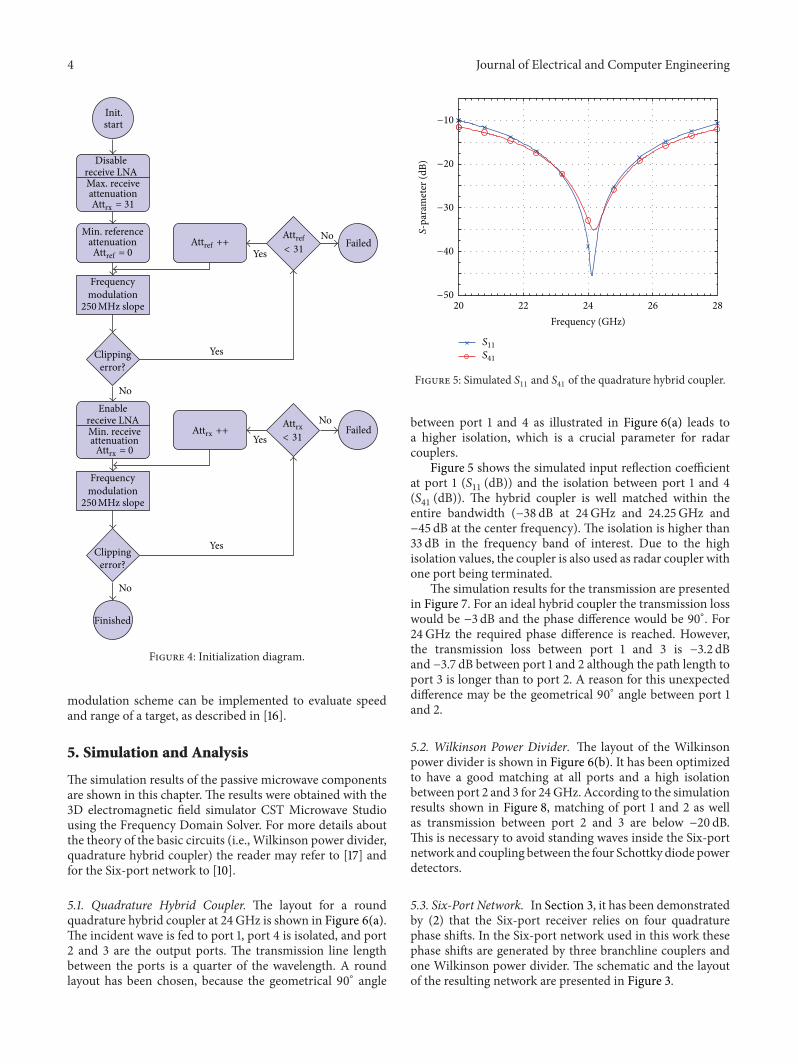
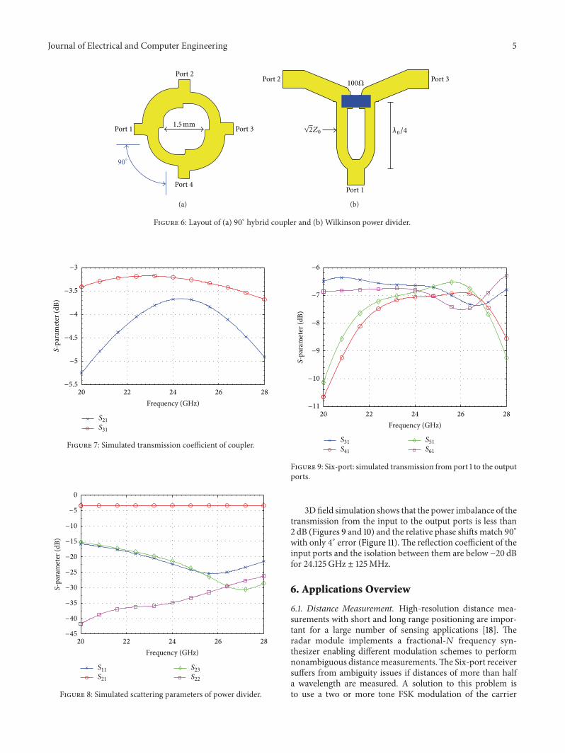
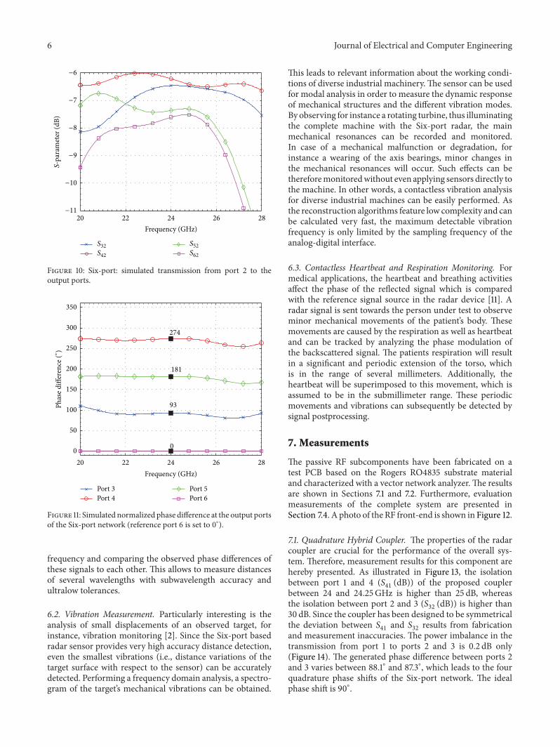
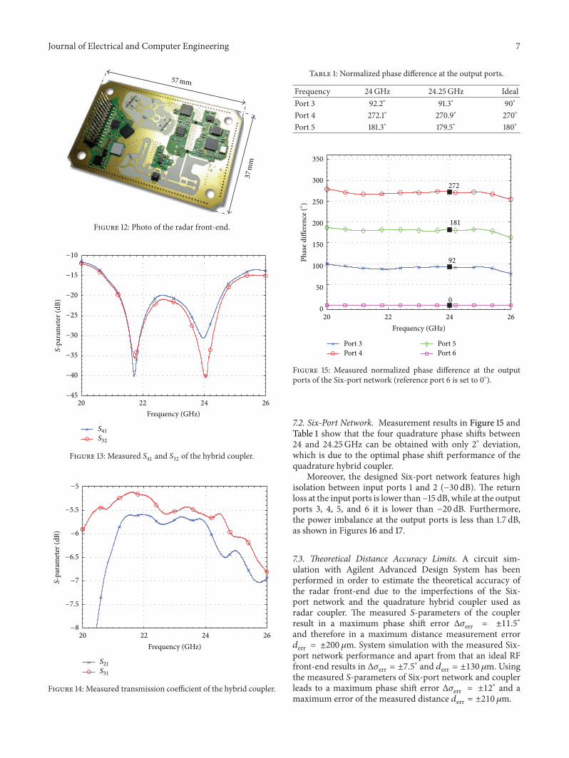
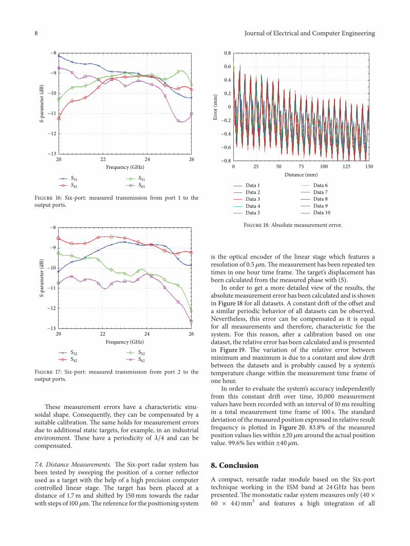
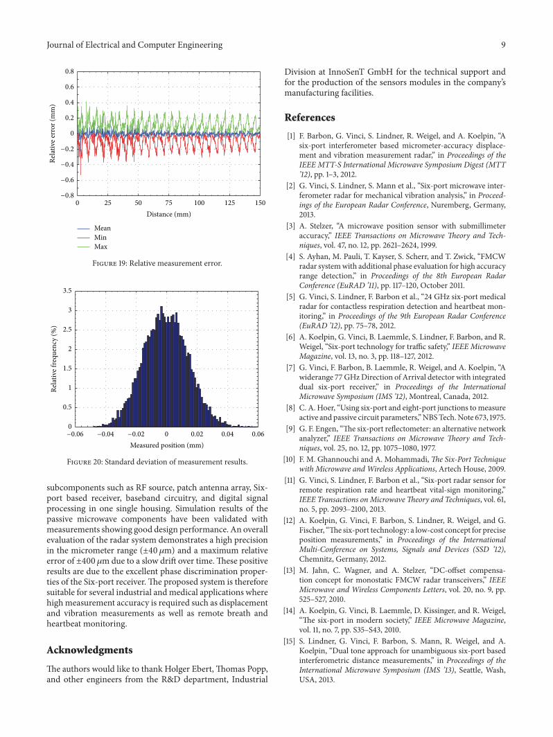

International Journal of
AerospaceEngineeringHindawi Publishing Corporationhttpwwwhindawicom Volume 2014
RoboticsJournal of
Hindawi Publishing Corporationhttpwwwhindawicom Volume 2014
Hindawi Publishing Corporationhttpwwwhindawicom Volume 2014
Active and Passive Electronic Components
Control Scienceand Engineering
Journal of
Hindawi Publishing Corporationhttpwwwhindawicom Volume 2014
International Journal of
RotatingMachinery
Hindawi Publishing Corporationhttpwwwhindawicom Volume 2014
Hindawi Publishing Corporation httpwwwhindawicom
Journal ofEngineeringVolume 2014
Submit your manuscripts athttpwwwhindawicom
VLSI Design
Hindawi Publishing Corporationhttpwwwhindawicom Volume 2014
Hindawi Publishing Corporationhttpwwwhindawicom Volume 2014
Shock and Vibration
Hindawi Publishing Corporationhttpwwwhindawicom Volume 2014
Civil EngineeringAdvances in
Acoustics and VibrationAdvances in
Hindawi Publishing Corporationhttpwwwhindawicom Volume 2014
Hindawi Publishing Corporationhttpwwwhindawicom Volume 2014
Electrical and Computer Engineering
Journal of
Advances inOptoElectronics
Hindawi Publishing Corporation httpwwwhindawicom
Volume 2014
The Scientific World JournalHindawi Publishing Corporation httpwwwhindawicom Volume 2014
SensorsJournal of
Hindawi Publishing Corporationhttpwwwhindawicom Volume 2014
Modelling amp Simulation in EngineeringHindawi Publishing Corporation httpwwwhindawicom Volume 2014
Hindawi Publishing Corporationhttpwwwhindawicom Volume 2014
Chemical EngineeringInternational Journal of Antennas and
Propagation
International Journal of
Hindawi Publishing Corporationhttpwwwhindawicom Volume 2014
Hindawi Publishing Corporationhttpwwwhindawicom Volume 2014
Navigation and Observation
International Journal of
Hindawi Publishing Corporationhttpwwwhindawicom Volume 2014
DistributedSensor Networks
International Journal of