Embed Size (px)
Citation preview

International Scholarly Research NetworkISRN Mechanical EngineeringVolume 2011, Article ID 542840, 6 pagesdoi:10.5402/2011/542840
Research Article
Exergy Analysis of Porous Medium Combustion Engine Cycle
N. Ravi Kumar
Department of Mechanical Engineering, MVGR College of Engineering, Vizianagaram 535005, India
Correspondence should be addressed to N. Ravi Kumar, ravi [email protected]
Received 17 July 2011; Accepted 14 August 2011
Academic Editors: C. Del Vecchio and C. F. Gao
Copyright © 2011 N. Ravi Kumar. This is an open access article distributed under the Creative Commons Attribution License,which permits unrestricted use, distribution, and reproduction in any medium, provided the original work is properly cited.
The need of the fossil fuels is ever increasing in the areas of manufacturing, transportation, heating, and electricity. Nearly 90%of the energy requirement in transport sector is met by combustion of fossil fuels only. Porous media (PM) combustion is aneffective method, which can increase the combustion efficiency as well as minimize environmental pollution. The present paper isaimed at thermodynamic analysis of ideal IC engine cycles with porous media combustion. Two practically possible cycles, namely,periodic and permanent contact of gas with porous medium are considered, and the ideal cycle analyses are made. It is found thatPM engine with periodic contact is more efficient than permanent contact type. The exergy analysis also reveals that the energyloss due to irreversibilities in the periodic contact type is less than that of the permanent contact type. With the help of modelcalculations and graphs, the performance of these two cycles is compared and optimal operating conditions are also evaluated andpresented along with the suggestions for enhancing the performance of homogeneous PM combustion in IC engines.
1. Introduction
Combustion is one of the oldest technologies of mankind.It has been used for more than one million years for dif-ferent purposes. At present, about ninety percent worldwideenergy demand is met by combustion of fuels derived fromdepletion fossil fuel reserves. To cope up with the impendingfuel crisis due to the increasing demand and depleting fossilfuel reserves, there is a need to further improve the perfor-mance of existing combustion systems and also to reduce theemissions levels to meet the emission norms. Porous mediumcombustion (PMC) is one such technology that has manyadvantages over the existing combustion systems. The stead-ily increasing use of fossil fuel has threatened the sustain-ability of life on the earth, since combustion of fossil fuelleads to increase in the emission levels in the atmosphere.Hence, to reduce the pollution level, there is always ademand for development and use of modern efficienttechnology for combustion of fossil fuel. In recent times,many researchers have developed several newer methodsfor efficient combustion of fossil fuel. Durst and Weclas[1] established that porous media combustion (PMC) isone such effective method, which can increase the systemefficiency as well as minimize environmental pollution.
This technology is entirely different from conventionalcombustion, which is characterized by a free flame, thinreaction zone, and high temperature gradients. It has gotseveral advantages over conventional combustion systems.In conventional combustion device, the entire combustiontakes in the gaseous environment, whereas in porous media,combustion takes place in a 3D solid porous matrix havinginterconnected pores. Compared to conventional combus-tion device, the combustion efficiency of porous mediumcombustor is reasonably high. This increase in efficiencyis the outcome of better heat transfer through solid-to-solid conduction and high radiation from the heated solidsurface. PMC devices can be classified [1] into two categories,namely, the one in which the combustion is fully confinedwithin the pores of the porous structure and the other onein which the combustion takes place over the surface of theporous matrix.
Durst and Weclas [2] proposed a new combustionconcept that fulfills the requirement to perform homoge-neous combustion in IC engine using porous medium. Thethermodynamics of PM engine is explained by consideringfour theoretical possible cycles, namely, Carnot cycle, idealconstant volume combustion cycle, periodic contact, andpermanent contact of gas with PM engine. They have

2 ISRN Mechanical Engineering
identified that the most realistic cycles for pm combustionare periodic contact and permanent contact types. Further,they have explained the operation of the engine with thesecycles. However, they have not taken up the detailed ther-modynamic analysis to identify the optimum operating pa-rameters to maximize the efficiency of the cycle. Huang et al.[3] studied some of the aspects of different initial preheatingconditions, which could affect the initiation and extinctionof super adiabatic combustion (SAC) as well as the subse-quent combustion modes in a porous medium. Jugjai andRungsimuntuchart [4] used the heat recirculation systembased on the PM technology in combination with swirlingcentral flow burner to improve the efficiency of the domesticgas burners. Jia and Hsieh [5] conducted experiments inthe PM heating burners using the liquefied petroleum gas(LPG) under steady state and transient conditions. Hereported a particular phenomenon called metastable com-bustion along with emission of CO and NOx. Ravirajand Ellzey [6] conducted experiments to understand thetransient behavior of fuel rich PMC with the conversionof methane to hydrogen. Rakopoulos and Giakoumis [7]survey the publications available in the literature concerningthe application of the second law of thermodynamics tointernal combustion engines. They discussed the main resultsbetween the first law and second law analysis. Nield [8]done a critical review of the modeling of viscous dissipationin a saturated porous medium, with applications to eitherforced convection or natural convection. However, it isfelt that effective implementation and efficient use of PMcombustion in IC engines is possible only when a detailedthermodynamic analysis of the realistic cycle is availablewhich has not been completely done. Thus, the presentpaper is aimed at identifying the effects of various operatingparameters on the efficiency of the different cycles possiblefor the operation of a porous medium engine. The exergyanalysis of the ideal cycle is also taken up to consider theminimization of waste heat through exhaust gases. Bothpermanent and periodic gas contact type pm engine cyclesare analyzed, and results are presented in graphical form,which will be useful in deciding the parameters suitable forpractical operation of a porous medium engine.
2. Model Development
Homogenization of the combustion process is the basicconcept in PM engine through fuel vaporization, mixing,and energy recirculation in a porous medium. Part of theheat energy of the burned gases is transferred to the porousmedium. This energy is utilized back in the cylinder forvaporization of liquid fuel. The practical realization of thisconcept in a more realistic way is possible according to Durstand Weclas [2] only in two ways, one is the periodic contacttype and the other one permanent contact type. Periodiccontact system requires a porous medium chamber; thatis, an open chamber which is thermally isolated from thehead walls and the permanent contact type requires an openchamber to be mounted in the cylinder head. Figure 1 showsP-V and T-S diagrams of two types of PM engine cycles
that are considered for analysis, namely, periodic contact andpermanent contact type. 1-2-3-4-5 is the periodic contactcycle and 1-2′-3-4-5 is the permanent contact cycle.
The periodic contact system requires a valve permittingcontact between PM chamber and the cylinder volume. Thecontrol of PM-chamber gases is permitted through valvetiming. Liquid fuel is injected in to PM volume, and timeavailable for this process and for fuel vaporization is assumedvery long. The vaporization process is independent of thespray atomization, engine load, or the engine rotationalspeed. Because the fuel is injected into the compressed gaswith a very low oxidant concentration, the resulting mixturein PM cannot ignite, even under high gas/PM temperature.This noncombustible gaseous charge formed in the PMvolume is injected back to the cylinder when the PM chambervalve opens, since the pressure in the PM chamber is muchhigher than the cylinder pressure. This high-pressure gasdischarge from the PM chamber to the cylinder generates ahighly turbulent flow conditions in the cylinder supportingmixing and homogenization of the cylinder charge. Theother processes (exhaust, suction, and compression) con-tinue in the cylinder without any contact with the PM cham-ber content.
In case of a permanent contact cycle, there is a permanentcontact between working gas and PM volume. The PMcombustion chamber is mounted in the head, and duringintake there is a weak influence of PM heat capacitor on thein-cylinder air. Further, during compression also there is asmall amount of air in contact with hot porous medium. Theinteraction increases as compression continues, and at TDCthe whole air is assumed to be in the PM volume. Near TDC,the heat is released into PM volume. The other processes areas same as in periodic cycle.
3. Analysis
The exergy method is a rich and powerful tool for ana-lyzing and understanding the processes as well as processoptimization. The main purpose of the exergy analysis isidentifying the sources of inefficiencies and discovering thecause of imperfection. Further, the exergy analysis is useful inunderstanding the influence of thermodynamic phenomenaon the process effectiveness and helps in comparison ofdifferent thermodynamic factors. It is also useful in determi-nation of the most effective ways of improving the analyzedprocesses [8–10]. The following assumptions are made in theanalysis of two cycles: (1) all the processes are ideal, (2) itis a closed cycle, (3) the working medium is air alone, (4)the properties of air remain constant throughout, (5) thereis no regeneration of exhaust gases, and (6) the inlet airtemperature is assumed as atmospheric condition, that is,T1 = T0.
3.1. Periodic Contact Cycle. Cycle 1-2-3-4-5 of Figure 1represents the periodic contact cycle where the gases aftercomplete compression comes in contact with hot porous

ISRN Mechanical Engineering 3
1
3
4
Vs
2
2
Vc
5
P
V
PVn = C
PVγ = C
1 2 3 4 5–periodic
1 2 3 4 5–permanent
PV = C
(a) P-V Diagram
43
2
2
5
1
PVn = C
1 2 3 4 5–periodic
1 2 3 4 5–permanent
S
PV = C
T
(b) T-S Diagram
Figure 1: Ideal cycles for periodic and permanent pm combustion engine.
plug. Gases are ideally compressed from (1) and (2) in whichthe compression ratio of the cycle is given by
rc = V1
V2= V1
V3= Vs + Vc
Vc. (1)
After compression, the gases are made to come in contactwith hot PM chamber during which it is isothermally heatedas shown in the process (3) and (4). In diesel and dualcycles, cutoff ratio is defined as the ratio of volumes in aconstant pressure process. In the present cycle the volumeratio is considered in isothermal process, hence representedas modified cutoff ratio (ρ′):
rc = re ∗ ρ′. (2)
Thus, the temperature at the end of expansion process can berelated to the above parameters as
T5 = T4
rγ−1e
= α∗ T2
rγ−1e
= α∗ T1 ∗ rγ−1c
rγ−1e
= α(ρ′)γ−1 ∗ T1.
(3)
Hence, the thermal efficiency of the periodic contact cycle is
ηperiodic = 1− Cv(T5 − T1)RT3 ln(V4/V3) + Cv(T3 − T2)
= 1− (T5 − T1)(γ − 1
)T3 ln ρ′ + (T3 − T2)
.
(4)
For the purpose of establishing the second law efficiency, theexergy analysis of the cycle is taken up by considering theirreversibility in all the processes of the cycle 1-2-3-4-5-1 as
I2−3 = T0
[Cv ln
T3
T2+Q3−2
T3
],
I5−1 = T0
[Cv ln
T1
T5+Q5−1
T1
].
(5)
3.2. Permanent Contact Cycle. Cycle 1-2′-3-4-5-1 is the per-manent contact cycle as shown in Figure 1, Gases are ideallycompressed from (1) and (2):
rc = V1
V3= V1
V ′2× V ′
2
V3= r × rAF, (6)
where rAF is the adiabatic compression factor:
T3 = T′2(rAF)n−1. (7)
The total heat supplied in the cycle is equal to
γ − n
n− 1×mCv
(T′2 − T3
)+ mRT3 ln
(V4
V3
). (8)
Thermal efficiency of permanent contact cycle is
ηpermanent
=1− Cv(T5 − T1)RT3 ln(V4/V3)+
((γ−n)/(n−1)
)Cv(T′2 − T3)
=1− (T5 − T1)(γ−1
)T3 ln(V4/V3)+
((γ−n)/(n−1)
)(T′2−T3)
.
(9)
4 ISRN Mechanical Engineering
T1 = 300 K, Tmax = 1200 K
Effi
cien
cy,η
(%)
6 8 10 12 14 16 18 20 22
100
90
80
70
60
50
40
ρ′ = 1.2, rAF = 1.2
Periodic, first lawPeriodic, second law
Permanent, first lawPermanent, second law
Compression ratio, rc
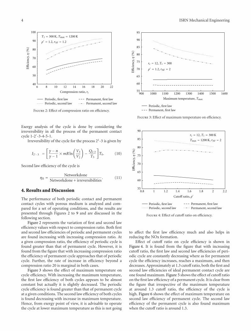
Figure 2: Effect of compression ratio on efficiency.
Exergy analysis of the cycle is done by considering theirreversibility in all the process of the permanent contactcycle 1-2′-3-4-5-1.
Irreversibility of the cycle for the process 21-3 is given by
I2′- 3 =[γ − n
γ − 1×mR ln
(V3
V ′2
)
− Q2-3
T3
]
T0. (10)
Second law efficiency of the cycle is
ηII = NetworkdoneNetworkdone + irreversibilities
. (11)
4. Results and Discussion
The performance of both periodic contact and permanentcontact cycles with porous medium is analyzed and com-pared for a set of operating conditions, and the results arepresented through Figures 2 to 9 and are discussed in thefollowing section.
Figure 2 represents the variation of first and second lawefficiency values with respect to compression ratio. Both firstand second law efficiencies of periodic and permanent cyclesare found increasing with increasing compression ratio. Ata given compression ratio, the efficiency of periodic cycle isfound greater than that of permanent cycle. However, it isfound from the figure that with increasing compression ratiothe efficiency of permanent cycle approaches that of periodiccycle. Further, the rate of increase in efficiency beyond acompression ratio 20 is marginal in both cases.
Figure 3 shows the effect of maximum temperature oncycle efficiency. With increasing the maximum temperature,the first law efficiency of both cycles appears to be almostconstant but actually it is slightly decreased. The periodiccycle efficiency is found greater than that of permanent cycleat a given conditions. The second law efficiency of both cyclesis found decreasing with increase in maximum temperature.Hence, from exergy point of view, it is advisable to operatethe cycle at lower maximum temperature as this is not going
95
90
85
80
75
70
65
60
55900 1000 1100 1200 1300 1400 1500 1600
Periodic, first lawPermanent, first law
rc = 12, T1 = 300
ρ′ = 1.2, rAF = 2
Maximum temperature, Tmax
Effi
cien
cy,η
(%)
Figure 3: Effect of maximum temperature on efficiency.
90
85
80
75
70
65
60
550.8 1 1.2 1.4 1.6 1.8 2 2.2
rc = 12, T1 = 300 K
Tmax = 1200 K, rAF = 2
Periodic, first lawPeriodic, second law
Permanent, first lawPermanent, second law
Effi
cien
cy,η
(%)
Cutoff ratio, ρ
Figure 4: Effect of cutoff ratio on efficiency.
to affect the first law efficiency much and also helps inreducing the NOx formation.
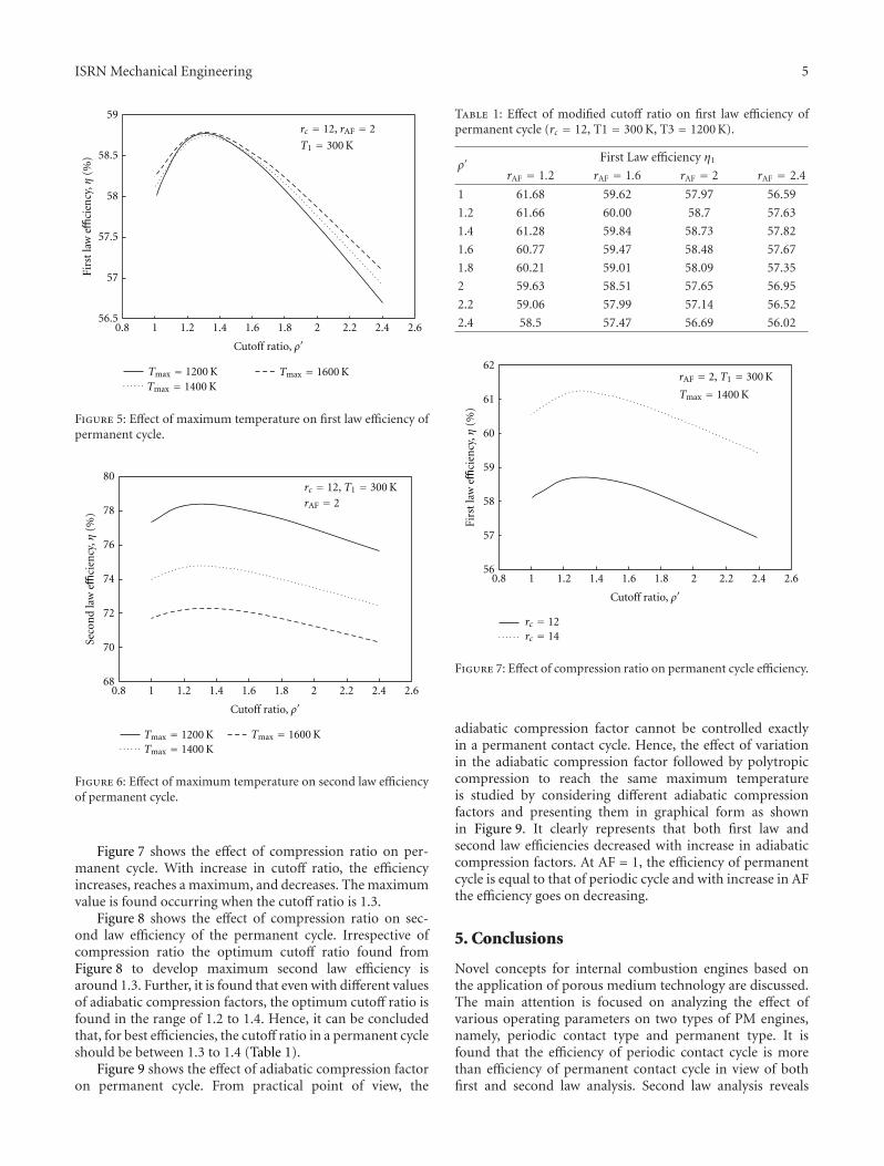
Effect of cutoff ratio on cycle efficiency is shown inFigure 4. It is found from the figure that with increasingcutoff ratio, the first law and second law efficiencies of peri-odic cycle are constantly decreasing where as for permanentcycle the efficiency increases, reaches a maximum, and thendecreases. Approximately at 1.3 cutoff ratio, both the first andsecond law efficiencies of ideal permanent contact cycle areone found maximum. Figure 5 shows the effect of cutoff ratioon the first law efficiency of a permanent cycle. It is clear fromthe figure that irrespective of the maximum temperatureat around 1.3 cutoff ratio, the efficiency of the cycle ishigh. Figure 6 shows the effect of maximum temperature onsecond law efficiency of permanent cycle. The second lawefficiency of the permanent cycle is also found maximumwhen the cutoff ratio is around 1.3.
ISRN Mechanical Engineering 5
59
58.5
58
57.5
57
56.50.8 1 1.2 1.4 1.6 1.8 2 2.2 2.4 2.6
rc = 12, rAF = 2
T1 = 300 K
Tmax = 1200 KTmax = 1400 K
Tmax = 1600 K
Firs
tla
weffi
cien
cy,η
(%)
Cutoff ratio, ρ
Figure 5: Effect of maximum temperature on first law efficiency ofpermanent cycle.
0.8 1 1.2 1.4 1.6 1.8 2 2.2 2.4 2.6
Tmax = 1200 KTmax = 1400 K
Tmax = 1600 K
rc = 12, T1 = 300 K
rAF = 2
80
78
76
74
72
70
68
Seco
nd
law
effici
ency
,η(%
)
Cutoff ratio, ρ
Figure 6: Effect of maximum temperature on second law efficiencyof permanent cycle.
Figure 7 shows the effect of compression ratio on per-manent cycle. With increase in cutoff ratio, the efficiencyincreases, reaches a maximum, and decreases. The maximumvalue is found occurring when the cutoff ratio is 1.3.
Figure 8 shows the effect of compression ratio on sec-ond law efficiency of the permanent cycle. Irrespective ofcompression ratio the optimum cutoff ratio found fromFigure 8 to develop maximum second law efficiency isaround 1.3. Further, it is found that even with different valuesof adiabatic compression factors, the optimum cutoff ratio isfound in the range of 1.2 to 1.4. Hence, it can be concludedthat, for best efficiencies, the cutoff ratio in a permanent cycleshould be between 1.3 to 1.4 (Table 1).
Figure 9 shows the effect of adiabatic compression factoron permanent cycle. From practical point of view, the
Table 1: Effect of modified cutoff ratio on first law efficiency ofpermanent cycle (rc = 12, T1 = 300 K, T3 = 1200 K).
ρ′First Law efficiency η1
rAF = 1.2 rAF = 1.6 rAF = 2 rAF = 2.4
1 61.68 59.62 57.97 56.59
1.2 61.66 60.00 58.7 57.63
1.4 61.28 59.84 58.73 57.82
1.6 60.77 59.47 58.48 57.67
1.8 60.21 59.01 58.09 57.35
2 59.63 58.51 57.65 56.95
2.2 59.06 57.99 57.14 56.52
2.4 58.5 57.47 56.69 56.02
Tmax = 1400 K
rc = 12rc = 14
62
61
60
59
58
57
560.8 1 1.2 1.4 1.6 1.8 2 2.2 2.4 2.6
Firs
tla
weffi
cien
cy,η
(%)
rAF = 2, T1 = 300 K
Cutoff ratio, ρ
Figure 7: Effect of compression ratio on permanent cycle efficiency.
adiabatic compression factor cannot be controlled exactlyin a permanent contact cycle. Hence, the effect of variationin the adiabatic compression factor followed by polytropiccompression to reach the same maximum temperatureis studied by considering different adiabatic compressionfactors and presenting them in graphical form as shownin Figure 9. It clearly represents that both first law andsecond law efficiencies decreased with increase in adiabaticcompression factors. At AF = 1, the efficiency of permanentcycle is equal to that of periodic cycle and with increase in AFthe efficiency goes on decreasing.
5. Conclusions
Novel concepts for internal combustion engines based onthe application of porous medium technology are discussed.The main attention is focused on analyzing the effect ofvarious operating parameters on two types of PM engines,namely, periodic contact type and permanent type. It isfound that the efficiency of periodic contact cycle is morethan efficiency of permanent contact cycle in view of bothfirst and second law analysis. Second law analysis reveals

6 ISRN Mechanical Engineering
Tmax = 1400 K
0.8 1 1.2 1.4 1.6 1.8 2 2.2 2.4 2.6
79
78
77
76
75
74
73
72
rc = 12rc = 14
rAF = 2, T1 = 300 K
Seco
nd
law
effici
ency
,η(%
)
Cutoff ratio, ρ
Figure 8: Effect of compression ratio on permanent cycle secondlaw efficiency.
85
80
75
70
65
60
551 1.2 1.4 1.6 1.8 2 2.2 2.4 2.6 2.8 3
T1 = 300 K, Tmax = 1400 K
ρ′ = 1.6
Adiabatic compression factor, rAF
rc = 12, first lawrc = 12, second law
rc = 14, first lawrc = 14, second law
Effi
cien
cy,η
(%)
Figure 9: Effect of adiabatic compression factor on permanentcycle.
that increase in maximum temperature in the cycle causesdecrease in efficiency of the cycle. It is also found that theoptimum cutoff ratio of the cycle is in the range of 1.2 to1.4 and the efficiency of the cycle decreases with increase inadiabatic compression factor.
Nomenclature
cp: Specific heat, kJ/kg Kcv: Calorific value, kJ/kgh: Enthalpy, kJ/kgI : Irreversibility, kJ/kgPM: Porous mediumrc : Compression ratios: Entropy, kJ/kg KT : Temperature, KV : Volume, m3
w: Work done, kJ/kg.
Suffix
AF: Adiabatic compression Factorc: Compressione: Expansionr: Rejection1, 2, 3 . . .: Thermodynamic states in the cycle.
Greek Symbols
η: Efficiencyρ1: Modified cutoff ratioγ: Ratio of specific heatsn: Polytropic index of compression.
References
[1] F. Durst and M. Weclas, “A new type of internal combustionengine based on the porous-medium combustion technique,”Journal of Automobile Engineering Institution of MechanicalEngineers: Part D, vol. 215, no. 1, pp. 63–81, 2001.
[2] F. Durst and M. Weclas, “A new concept of I.C.Enginewith homogeneous combustion in a porous medium,” inProceedings of the 5th International Symposium on Diagnosticsand Modeling of Combustion in Internal Combustion Engines(COMODIA ’01), Nagoya, Japan, July 2011.
[3] Y. Huang, C. Y. H. Chao, and P. Cheng, “Effects of preheat-ing and operation conditions on combustion in a porousmedium,” International Journal of Heat and Mass Transfer, vol.45, no. 21, pp. 4315–4324, 2002.
[4] S. Jugjai and N. Rungsimuntuchart, “High efficiency heat-recirculating domestic gas burners,” Experimental Thermaland Fluid Science, vol. 26, no. 5, pp. 581–592, 2002.
[5] F. L. Jia and W. H. Hsieh, “Experimental investigation ofcombustion in porous heating burners,” Combustion andFlame, vol. 138, no. 3, pp. 295–303, 2004.
[6] S. D. Raviraj and J. L. Ellzey, “Numerical and experimentalstudy of the conversion of methane to hydrogen in a porousmedia reactor,” Combustion and Flame, vol. 144, no. 4, pp.698–709, 2006.
[7] C. D. Rakopoulos and E. G. Giakoumis, “Second-law analysesapplied to internal combustion engines operation,” Progress inEnergy and Combustion Science, vol. 32, no. 1, pp. 2–47, 2006.
[8] D. A. Nield, “The modeling of viscous dissipation in a sat-urated porous medium,” Journal of Heat Transfer, vol. 129, no.10, pp. 1459–1463, 2007.
[9] V. K. Pantangi and S. C. Mishra, “Combustion of gaseous hy-drocarbon fuels within porous media—a review,” in Proceed-ings of the National Conference on Advances in Energy Research(AER ’06), pp. 455–461, 2006.
[10] T. Kotas, The Exergy Method of Thermal Plant Analysis, KriegerPublishing Company, Malabar, Fla, USA, 1995.

International Journal of
AerospaceEngineeringHindawi Publishing Corporationhttp://www.hindawi.com Volume 2010
RoboticsJournal of
Hindawi Publishing Corporationhttp://www.hindawi.com Volume 2014
Hindawi Publishing Corporationhttp://www.hindawi.com Volume 2014
Active and Passive Electronic Components
Control Scienceand Engineering
Journal of
Hindawi Publishing Corporationhttp://www.hindawi.com Volume 2014
International Journal of
RotatingMachinery
Hindawi Publishing Corporationhttp://www.hindawi.com Volume 2014
Hindawi Publishing Corporation http://www.hindawi.com
Journal ofEngineeringVolume 2014
Submit your manuscripts athttp://www.hindawi.com
VLSI Design
Hindawi Publishing Corporationhttp://www.hindawi.com Volume 2014
Hindawi Publishing Corporationhttp://www.hindawi.com Volume 2014
Shock and Vibration
Hindawi Publishing Corporationhttp://www.hindawi.com Volume 2014
Civil EngineeringAdvances in
Acoustics and VibrationAdvances in
Hindawi Publishing Corporationhttp://www.hindawi.com Volume 2014
Hindawi Publishing Corporationhttp://www.hindawi.com Volume 2014
Electrical and Computer Engineering
Journal of
Advances inOptoElectronics
Hindawi Publishing Corporation http://www.hindawi.com
Volume 2014
The Scientific World JournalHindawi Publishing Corporation http://www.hindawi.com Volume 2014
SensorsJournal of
Hindawi Publishing Corporationhttp://www.hindawi.com Volume 2014
Modelling & Simulation in EngineeringHindawi Publishing Corporation http://www.hindawi.com Volume 2014
Hindawi Publishing Corporationhttp://www.hindawi.com Volume 2014
Chemical EngineeringInternational Journal of Antennas and
Propagation
International Journal of
Hindawi Publishing Corporationhttp://www.hindawi.com Volume 2014
Hindawi Publishing Corporationhttp://www.hindawi.com Volume 2014
Navigation and Observation
International Journal of
Hindawi Publishing Corporationhttp://www.hindawi.com Volume 2014
DistributedSensor Networks
International Journal of