Embed Size (px)
Citation preview

Research ArticleAn Improved Shock Factor to Evaluate the Shock Environmentof Small-Sized Structures Subjected to Underwater Explosion
Wenzheng Zhang and Weikang Jiang
State Key Laboratory of Mechanical System and Vibration, Shanghai Jiao Tong University, Shanghai 200240, China
Correspondence should be addressed to Weikang Jiang; [email protected]
Received 9 October 2014; Revised 30 March 2015; Accepted 31 March 2015
Academic Editor: Wen Long Li
Copyright © 2015 W. Zhang and W. Jiang. This is an open access article distributed under the Creative Commons AttributionLicense, which permits unrestricted use, distribution, and reproduction in any medium, provided the original work is properlycited.
Shock factor is conventionally used to assess the effect of an underwater explosion on a target. The dimensions of some structuresare much smaller than the wavelength of incident wave induced by the underwater explosion. The conventional shock factor maybe excessively severe for small-sized structures because it neglects the effect of scattering; so it is necessary to study the shock factorfor small objects. The coupled mode method is applied to study the scattering field surrounding the cylindrical shells. A nonlinearrelation differential is derived from the impact received by the cylindrical shells and the ratio between the diameters of the shells andthe wavelength of the incident wave. An improved shock factor is developed based on the fitted curve, considering the scatteringeffect caused by the diameters of the submerged cylindrical shells. A set of numerical simulations are carried out to validate theaccuracy of the proposed approach. The results show that the cylindrical shells and spherical shells under different conditions, butwith the same shock factor, have almost the same shock responses.
1. Introduction
The dynamic responses and shock damage of the vesselssubjected to underwater explosion (UNDEX) are importantconcerns for naval researchers. Cylindrical shells and spheri-cal shells account for a large proportion in the vessels and off-shore structures, especially in surface ships and submarines.Therefore, the researches on the dynamic responses andshock environment of the cylindrical shells subjected tounderwater shock load make great significance in assessingthe impact resistance ability of submerged structures.
Full scale test is the most direct and effective method tostudy how the vessels dynamically respond to and are dam-aged by the underwater shock wave. However, conductingexperiments on full scale vessels is extremely expensive andthe budget is generally limited. Scaled models are good alter-natives for cost reduction and convenient manipulation. Cole[1] systematically summarized the theoretical achievementsand test phenomena related to UNDEX, and the empiricalformulas to predict the shock wave loading and dynamicresponses of the structures were also simplified. Brett et al.[2] investigated the dynamic responses of the steel cylinders
exposed to near-field explosion bymeasuring the accelerationand underwater pressure. Li et al. [3] compared the linearand nonlinear responses and damage modes of the unfilledand main hull sand-filled cylindrical shell models subjectedto underwater spherical explosion by a series of small-scaleexperiments. Chen et al. [4] experimentally investigatedthe strain and acceleration responses of a neoprene coatedcylinder subjected to UNDEX in an artificial lake.
Developing an analytical solution to theUNDEXproblemis extremely difficult because the dynamic responses of thevessels depend onmany factors, including the complex struc-tures, the detonation of the explosive charge, the propagationof the shock wave, the local cavitation, and the complicatedfluid-structure interaction (FSI). Therefore, the theoreticalstudies are only suitable for simple geometrical structures.Huang [5, 6] employed the series expansion method andLaplace transform to elucidate the transient FSI of planeacoustic waves with submerged spherical and cylindricalelastic shells. Geers [7, 8] obtained the responses of thesubmerged cylindrical shell exited by a transient plane waveby using the residual potential method. Zhang and Geers [9]presented the transient response histories of the submerged
Hindawi Publishing CorporationShock and VibrationVolume 2015, Article ID 451583, 11 pageshttp://dx.doi.org/10.1155/2015/451583

2 Shock and Vibration
fluid-filled spherical shell exposed to a plane step wave. Theseparation of variables method was adopted and the resultswere compared with that of an empty submerged steel shell.
Over the last decades, with the improvement of computertechnique and calculation procedure, a variety of numericalmethods have been rapidly developed to analyze the FSIproblem. The development of the finite element method(FEM) and boundary element method (BEM) makes itpossible to investigate the responses of submerged complexstructures subjected to noncontact UNDEX, and the small-scale model tests are frequently carried out to validatethe feasibility of the numerical methods. Kwon and Fox[10] studied the nonlinear dynamic response of a cylindersubjected to a side-on, far-field UNDEX by using bothnumerical and experimental techniques. Wardlaw and Luton[11] presented several close-in cases to document the FSImechanisms for internal and external UNDEX, and therigid and deformable body simulations were compared byapplying the coupled GEMINI–DYNA N code. Mair [12]indicated that only codes employing “structural elements”were realistically applicable to the analysis of thin-walledstructural response to UNDEX after reviewing the appli-cability of various hydrocode methodologies. Hung et al.[13] analyzed the linear and nonlinear dynamic responses ofthree cylindrical shell structures (unstiffened, internal, andexternal stiffened) subjected to small charge UNDEX in awater tank, and the dynamic accelerations and strains werecompared with those obtained by FEM. Jin and Ding [14]compared the dynamic acceleration and velocity responsesof a ship section between the experimental and numericalresults by using ABAQUS.
Among the numerical techniques developed for theFSI problem, particularly worth mentioning is the doublyasymptotic approximation (DAA) method. Geers [15, 16]applied approximations approach in the limit of low andhigh frequency motions by using the virtual mass and planewave approximation, and a smooth transition was effectedin the intermediate frequency range to analyze the dynamicresponses of the submerged structures subjected to UNDEX.Geers and Felippa [17] also studied the accuracy of the DAAforms through the numerical results of a submerged sphericalshell. Liang and Tai [18] presented time history of the shockwave and the dynamic responses of a patrol boat subjectedto underwater shock loading by using the FEM coupled withDAA. Lai [19] applied the time domain FEM/DAA couplingprocedure to predict the transient dynamic responses ofa submerged sphere shell with an opening subjected toUNDEX, and the results in the sea and air were alsocompared.
Most of the previous research mainly focused on thedeformation, damage, and buckling of the cylindrical shellssubjected to the shock wave. However, it is difficult toanalyze the scattered wave of structures by the fluid-structureinteraction method, and there are few studies on the incidentwave in analytical method. Therefore, the research on thescattered wave field of submerged structures by the analyticalmethods seems to be very imperative. When the character-istic dimensions of small-sized submerged structures, suchas towed vehicles and torpedoes, are much smaller than
the wavelength, the scattering effect should be taken intoconsideration. In this paper, the coupled mode method isapplied to decompose the incident wave into a series ofharmonic waves. The scattering effect of submerged cylin-drical shells is analyzed to verify that the conventionalshock factor is excessively severe for small-sized structures.Therefore, the conventional shock factor is revised accordingto the impulse received by the cylindrical shell, which takesin the scattering effect of the characteristic dimensions ofsubmerged structures. A set of numerical simulations arecarried out by using the commercial code to validate theaccuracy of the improved shock factor. Results show that theresponses of cylindrical shells and spherical shells in differentconditions are similar to each other when the improved shockfactor is unchanged.
2. Shock Wave Pressure of UNDEX
UNDEX is the major threat to surface ships and submarines.According to the dynamic responses and damage modes ofthe vessels, the noncontact UNDEX can be divided into twokinds: near-field explosion and far-field explosion. In a near-field UNDEX, the structures are within the maximum radius𝑅max of the first pulsation of the gas bubble, and the shockenergy of the explosive charge may cause great local damageto the vessels. For far-field UNDEX, the standoff distance𝑅 between the explosive charge and the structures is largerthan the maximum radius 𝑅max, and the explosion can causea wide range of nonrepair damage and failure of shipboardequipment. So the majority of the previous studies focus onthe far-field explosion.
During an UNDEX, the sudden release of the explosiveenergy generates a transitory and highly compressed shockwave and a series of gas bubble pulsations. Most tests indicatethat the damage and failure of the vessels occur at theearly time of an UDNEX and are caused by the primaryshock wave. The energy of the shock wave delivered tothe vessels depends on the explosive charge weight andstandoff distance. The shock wave is superimposed onto thehydrostatic pressure andpropagates into thewatermedium ina spherical shape.The time history of the shockwave at a fixedlocation starts with an instantaneous peak pressure in timedomain, followed by an exponentially decaying function.According to the empirical formula summarized by Cole[1] and Zamyshlyaev [20], the incident shock wave can beexpressed by
𝑝 (𝑡) = 𝑝𝑚𝑒−(𝑡−𝑡0)/𝜃, (1)
where 𝑝𝑚denotes the peak magnitude of the pressure at the
shock front; 𝜃 represents the time decay constant and 𝑡0is
the propagation time from the explosive to the target. Fortrinitrotoluene (TNT), the peak pressure 𝑝
𝑚and the time
decay constant 𝜃 are
𝑝𝑚= 𝐾1 (
𝑊1/3
𝑅)
𝛼1
Pa,
𝜃 = 𝐾2𝑊1/3
(𝑊
1/3
𝑅)
𝛼2
ms,
(2)
Shock and Vibration 3
where 𝑊 is the explosive charge weight, 𝑅 is the standoffdistance, and 𝐾1, 𝐾2, 𝛼1, and 𝛼2 are the shock parameters ofthe explosive.
3. Coupled Mode Method
Cylindrical shells account for a large proportion of sub-merged structures. Many analytical approaches to the scat-tered wave field of cylindrical shells have been developed,such as the coupled mode method, the finite differencetime domain method, and the reflected afterflow of virtualsource method. In this paper, the coupled mode method isintroduced to compute the scattered wave field by three-dimensional cylindrical shells for reducing computation timeand ensuring precision.
A variety of researches on scattered wave field of har-monic wave have been conducted [21], but the incident waveinduced by UNDEX is not a harmonic wave. It is necessaryto decompose the incident wave into a series of harmonicplane waves with various frequencies. The incident wave canbe expressed as
𝑝𝑖(𝑡) = 𝑝
𝑚𝑒−(𝑡−𝑡0)/𝜃. (3)
Assume V = 𝑡 − 𝑡0; then (3) is transformed into
𝑝𝑖(V) = 𝑝
𝑚𝑒−V/𝜃
, V > 0. (4)
The Fourier transform of (4) can be obtained:
𝑝𝑖(𝜔) = ∫
∞
−∞
𝑝𝑖(V) 𝑒−𝑗𝜔V𝑑V. (5)
The inverse Fourier transform of 𝑝𝑖(𝜔) is yielded as
𝑝𝑖(V) =
12𝜋
∫
∞
−∞
𝑝𝑖(𝜔) 𝑒𝑗𝜔V
𝑑𝜔. (6)
The incident wave can be regarded as plane wave, as thestandoff distance is usually very large for the small-sizedsubmerged structures. Hence, substituting (4) into (5) yields
𝑝𝑖(𝜔) =
𝑝𝑚
1/𝜃 + 𝑗𝜔. (7)
Substituting (7) into (6) yields
𝑝𝑖(V) = ∫
∞
−∞
𝑝𝑚
2𝜋√𝜔2 + 1/𝜃2𝑒𝑗(𝜔V−𝛾0)𝑑𝜔, (8)
where 𝛾0 = 𝜔𝜃.The schematic diagram of scattered wave field of sub-
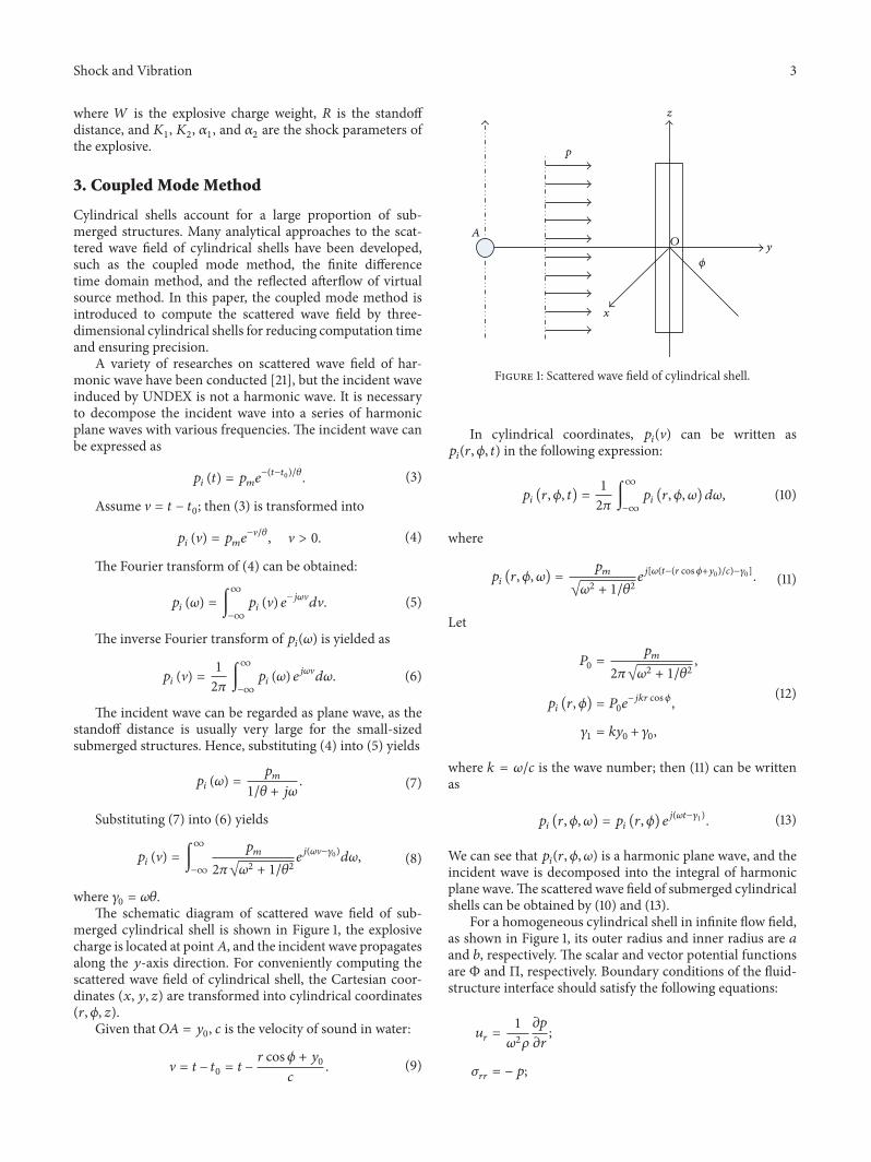
merged cylindrical shell is shown in Figure 1, the explosivecharge is located at point𝐴, and the incident wave propagatesalong the 𝑦-axis direction. For conveniently computing thescattered wave field of cylindrical shell, the Cartesian coor-dinates (𝑥, 𝑦, 𝑧) are transformed into cylindrical coordinates(𝑟, 𝜙, 𝑧).
Given that 𝑂𝐴 = 𝑦0, 𝑐 is the velocity of sound in water:
V = 𝑡 − 𝑡0 = 𝑡 −𝑟 cos𝜙 + 𝑦0
𝑐. (9)
A
z
y
x
O
𝜙
p
Figure 1: Scattered wave field of cylindrical shell.
In cylindrical coordinates, 𝑝𝑖(V) can be written as
𝑝𝑖(𝑟, 𝜙, 𝑡) in the following expression:
𝑝𝑖(𝑟, 𝜙, 𝑡) =
12𝜋
∫
∞
−∞
𝑝𝑖(𝑟, 𝜙, 𝜔) 𝑑𝜔, (10)
where
𝑝𝑖(𝑟, 𝜙, 𝜔) =
𝑝𝑚
√𝜔2 + 1/𝜃2𝑒𝑗[𝜔(𝑡−(𝑟 cos𝜙+𝑦0)/𝑐)−𝛾0]. (11)
Let
𝑃0 =𝑝𝑚
2𝜋√𝜔2 + 1/𝜃2,
𝑝𝑖(𝑟, 𝜙) = 𝑃0𝑒
−𝑗𝑘𝑟 cos𝜙,
𝛾1 = 𝑘𝑦0 + 𝛾0,
(12)
where 𝑘 = 𝜔/𝑐 is the wave number; then (11) can be writtenas
𝑝𝑖(𝑟, 𝜙, 𝜔) = 𝑝
𝑖(𝑟, 𝜙) 𝑒
𝑗(𝜔𝑡−𝛾1). (13)
We can see that 𝑝𝑖(𝑟, 𝜙, 𝜔) is a harmonic plane wave, and the
incident wave is decomposed into the integral of harmonicplane wave.The scattered wave field of submerged cylindricalshells can be obtained by (10) and (13).
For a homogeneous cylindrical shell in infinite flow field,as shown in Figure 1, its outer radius and inner radius are 𝑎and 𝑏, respectively. The scalar and vector potential functionsare Φ and Π, respectively. Boundary conditions of the fluid-structure interface should satisfy the following equations:
𝑢𝑟=
1𝜔2𝜌
𝜕𝑝
𝜕𝑟;
𝜎𝑟𝑟= −𝑝;
4 Shock and Vibration
𝜎𝑟𝜙
= 0,
𝑟 = 𝑎,
𝜎𝑟𝑟= 0;
𝜎𝑟𝜙
= 0,
𝑟 = 𝑏,
(14)
where 𝑢 and 𝜎 are displacement and stress, respectively. 𝜌 isthe density of the fluid, and 𝑝 is the total sound pressure ofharmonic wave components and can be written as
𝑝 = 𝑝𝑖(𝑟, 𝜙, 𝜔) + 𝑝
𝑠(𝑟, 𝜙, 𝜔) , (15)
where 𝑝𝑠(𝑟, 𝜙, 𝜔) is the sound pressure of the scattered wave
induced by harmonic wave components.The sound field can be decomposed in cylindrical func-
tions:
𝑝𝑖(𝑟, 𝜙, 𝜔)
=𝑝𝑚
√𝜔2 + 1/𝜃2𝑒𝑗(𝜔𝑡−𝛾1)
∞
∑
𝑛=0𝜀𝑛𝑗𝑛
𝐽𝑛(𝑘𝑟) cos 𝑛𝜙,
𝑝𝑠(𝑟, 𝜙, 𝜔)
=𝑝𝑚
√𝜔2 + 1/𝜃2𝑒𝑗(𝜔𝑡−𝛾1)
∞
∑
𝑛=0𝐴𝑛𝐻(2)𝑛
(𝑘𝑟) cos 𝑛𝜙.
(16)
The potential functions can be decomposed as
Φ =𝑝𝑚
√𝜔2 + 1/𝜃2
⋅ 𝑒𝑗(𝜔𝑡−𝛾1)
∞
∑
𝑛=0[𝐵𝑛𝐽𝑛(𝑘𝑙𝑟) +𝐶
𝑛𝑁𝑛(𝑘𝑙𝑟)] cos 𝑛𝜙,
Π =𝑝𝑚
√𝜔2 + 1/𝜃2
⋅ 𝑒𝑗(𝜔𝑡−𝛾1)
∞
∑
𝑛=1[𝐷𝑛𝐽𝑛(𝑘𝑡𝑟) +𝐸
𝑛𝑁𝑛(𝑘𝑡𝑟)] sin 𝑛𝜙,
(17)
where 𝜀𝑛
= 1 for 𝑛 = 0 and 𝜀𝑛
= 2 for 𝑛 > 0. 𝐽𝑛and
𝑁𝑛are, respectively, Bessel function and Neumann function
of order 𝑛. 𝐻(2)𝑛
is Hankel function of the second kind oforder 𝑛. Substituting (16) and (17) into geometric equation,constructive equation, and wave equation [22], a group offunctions of undetermined coefficients can be obtained as
𝑀𝑃 = 𝑈, (18)
where coefficient matrix 𝑀 is a square matrix of order 5and 𝑈 and 𝑃 are column vectors of order 5. Undeterminedcoefficients 𝑃 = [𝐴
𝑛, 𝐵𝑛, 𝐶𝑛, 𝐷𝑛, 𝐸𝑛]𝑇 can be obtained by
solving the linear equation. Thus the scattered wave field
can be expressed by the harmonic waves. The pressuredistribution on the surface of cylindrical shell is given by
𝑝 (𝑎, 𝜙, 𝜔) =𝑝𝑚
√𝜔2 + 1/𝜃2
⋅ 𝑒𝑗(𝜔𝑡−𝛾1)
∞
∑
𝑛=0[𝜀𝑛𝑗𝑛
𝐽𝑛(𝑘𝑎) +𝐴
𝑛𝐻(2)𝑛
(𝑘𝑎)] cos 𝑛𝜙.(19)
4. Shock Factor Revision
Shock factor is defined to describe the shock environment forsurface ships and submerged vessels subjected to UNDEX.The responses of structures which suffered from UNDEXshould be approximately similar to each otherwhen the shockfactor is unchanged. The widely used shock factor is
𝐶 =√𝑊
𝑅. (20)
It is defined in terms of equal shock energy sheltered bystructures based on the hypothesis of plane wave. The totalenergy of incident wave is
𝐸𝑡= 𝑊𝜌𝑒𝜂𝑒, (21)
where 𝜌𝑒is the chemical energy of explosive charge of unit
mass and 𝜂𝑒is the conversion rate from chemical energy
to incident wave energy. If the standoff distance is largeenough compared with the characteristic dimensions of thestructures, the incident wave can be regarded as plane wave.The energy sheltered by the structures is
𝐸𝑠= 𝐸𝑡
𝑆𝑒
4𝜋𝑅2 , (22)
where 𝑆𝑒is the projected area of structures in the vertical
incident wave front. Thus the relationship between 𝐶 and 𝐸𝑠
can be obtained as
𝐸𝑠=
𝜌𝑒𝜂𝑒𝑆𝑒𝐶
4𝜋. (23)
Generally, 𝑆𝑒is constant. So the sheltered energy 𝐸
𝑠is also
constant when the shock factor 𝐶 remains unchanged.The conventional shock factor 𝐶 is suitable to assess the
shock environment of surface ships and submarines. Whenthe characteristic dimension of submerged structures ismuchsmaller than the wavelength of incident wave induced byUNDEX, the scattered effect of submerged structures shouldbe taken into consideration. In this paper, a set of cylindricalshells with different diameters are applied to investigate howcharacteristic dimension affects the scattered wave field.
The schematic diagram of the cylindrical shells withdifferent diameters that suffered from an UNDEX is shownin Figure 3. For eliminating the effect of water surface, thecylindrical shells are set 50m underwater, and the cylindricalshells and explosive charge are placed at the same depth. Theshells are produced by using the stainless steel whose strain-stress curve is depicted in Figure 2. The material propertiesand the parameters of UNDEX are given in Table 1.

Shock and Vibration 5
Table 1: Material properties and parameters of UNDEX.
ParametersYoung’s modulus (GPa) 210Poisson’s ratio 0.3Mass density (km/m3) 7850Mass of explosive charge (kg) 1000Standoff distance (m) 100Length of shells (m) 20
0 0.2 0.4 0.6 0.8 10
200
400
600
800
1000
Strain 𝜀
𝜀-𝜎 relationship curve
Stre
ss𝜎
(MPa
)
Figure 2: Strain-stress curve of stainless steel.
The incident wave can be decomposed into a series ofharmonic waves, and the pressure distribution on the surfaceof cylindrical shells can be calculated by the coupled modemethod. So the time history of average pressure of centerpoint 1 on the front surface of the shell can be obtained. Coleextensively discussed the important meaning of impulse andenergy flux density, which can be used to estimate the initialvelocity of structures subjected to UNDEX.Then the impulseof point 1 in shock wave period is calculated to evaluatethe influence of the diameters of cylindrical shells on thescattered wave field. The impulse can be expressed as
𝐼 = ∫
6.7𝜃
0𝑝 (𝑡) 𝑑𝑡. (24)
It is well known that the frequency of the incident wavemakes a great influence on the meshing size of fluid elementin the fluid-structure interaction. The maximum frequencyof the incident wave can be defined as the reciprocal of pulsewidth [23]. As shown in Figure 4, the constant 𝜃 representsthe time duration from 𝑝
𝑚to 𝑝𝑚/𝑒. Thus the constant 𝜃
is defined as the pulse width of the incident wave and thewavelength can be calculated by 𝜆 = 𝑐𝜃.
The impulses of point 1 on the cylindrical shells withdifferent diameter are calculated, and the results are listedin Table 2. In the case analysis, the diameters range from0.1m to 5m, but the standoff distance remains constant. Itis obviously observed that the impulse significantly decreases
2
4
1
3
Explosive charge
d
L = 20m
Figure 3: Top view of cylindrical shell.
8
7
6
5
4
3
2
1
0
Pres
sure
of s
hock
wav
e (Pa
)
×106
Pm
T = 𝜃
Pm/e
Pressure versus time
0 1 2 3 4 5 6 7 8 9
Time (ms)
Figure 4: Incident wave with pulse width.
as the diameters reduce. This illustrates that the scatter effectshould be taken into consideration when the diameters ofcylindrical shells are much smaller than the wavelength ofthe incident wave. Figure 5 shows the relationship betweenthe impulses and the ratio 𝜂 = 𝑑/𝜆 by taking a nonlinearregression. The regressive curve is expressed as
𝐼 = 2377𝑒−0.19𝜆/𝑑 + 5269. (25)
In Figure 5, the impulse approximately begins to decreasewhen 𝑑/𝜆 < 2 and rapidly decays in an exponential functionwhen 𝑑/𝜆 < 1. It means that the collection pressure ofthe cylindrical shells decreases. This can be explained bythe fact that part of the shock energy diffracts when thediameters of the cylindrical shells are relatively smaller thanthe wavelength. Thus the conventional shock factor is toosevere for the small-sized submerged structures. In order

6 Shock and Vibration
Table 2: Calculated impulses of cylindrical shells with differentdiameters.
Cases Diameter (m) 𝑑/𝜆 Impulse (N∗m)1 0.1 0.07 54232 0.2 0.13 58593 0.3 0.2 61984 0.4 0.27 63755 0.5 0.34 65176 0.6 0.4 67057 0.7 0.47 68828 0.8 0.54 69979 0.9 0.61 708810 1 0.67 719311 1.5 1.01 729512 2 1.35 732313 2.5 1.69 738414 3 2.04 741215 4 2.7 743916 5 3.33 7451
0 0.5 1 1.5 2 2.5 3 3.5 4 4.5 55000
5500
6000
6500
7000
7500
8000
Calculated data
d/𝜆
I = 2377e−0.19𝜆/d
+ 5269
Impu
lse (N
∗m
)
Figure 5: Schematic diagram of regression curve.
to revise the scattering effect, an improved shock factor isdefined as
𝐶𝑚= 𝐶𝑒−0.19𝜆/𝑑
=√𝑊
𝑅𝑒−0.0233 3
√𝑊(3√𝑊/𝑅)
−0.23/𝑑
, (26)
where 𝑑 is the characteristic dimension of submerged struc-tures. The relationship between the improved shock factorand conventional shock factor is depicted in Figure 6. It isobserved that the improved shock factor clearly differs fromthe conventional one just when the characteristic dimensionis relatively smaller than the wavelength. There is almost nodifference between them when the characteristic dimensionis much larger than the wavelength.
0 1 2 3 4 5 6 7 8 9 100.1
0.2
0.3
0.4
0.5
0.6
0.7
0.8
0.9
1
d/𝜆
Cm/C
Cm/C
Figure 6: The relationship between the improved and conventionalshock factors.
X
YZ
Figure 7:The finite elementmodel of the cylindrical shell andwater.
5. Numerical Simulations
In the past decades, numerical methods have been developedrapidly and applied successfully to analyze the responses ofsubmerged structures under shock loading. To verify theaccuracy of the coupled mode method, some conditionsin Table 2 are simulated by commercial code. As shown inFigure 7, the cylindrical shell and the outer fluid field aremodeled by using the shell element and acoustics element,respectively, and an impedance-type radiation boundarycondition is applied at the outer surface of the fluid mesh.
The time histories of acoustic pressure at point 1 on thefront surface of the cylindrical shells are illustrated in Figure 8to compare with that calculated by using the coupled modemethod. It is observed that both the peak values and theattenuation trend are in good accordance with each other.Meanwhile, there is a disability for the coupledmodemethod

Shock and Vibration 7
0 5 10 15 20 25 30
0
0.5
1
1.5
2
2.5
3
3.5
4
Time (ms)
Soun
d pr
essu
re (P
a)×10
6
−0.5
(a) Case 3: 𝑑 = 0.3m
0 5 10 15 20 25 30
0
0.5
1
1.5
2
2.5
3
3.5
4
Time (ms)
Soun
d pr
essu
re (P
a)
×106
−0.5
(b) Case 7: 𝑑 = 0.7m
0 5 10 15 20 25 30
0
0.5
1
1.5
2
2.5
3
3.5
4
Time (ms)
Soun
d pr
essu
re (P
a)
Coupled mode methodNumerical simulation
×106
−0.5
(c) Case 10: 𝑑 = 1.0m
Time (ms)
Soun
d pr
essu
re (P
a)
Coupled mode methodNumerical simulation
0 5 10 15 20 25 30
0
0.5
1
1.5
2
2.5
3
3.5
4×10
6
−0.5
(d) Case 14: 𝑑 = 3.0mFigure 8: Comparison of the time history of sound pressure.
to calculate the reflection sound pressure from the cylindricalshells. The reflection sound pressure can be omitted due tosmall amplitude and short time.Therefore, the coupledmodemethod is possessed of high accuracy to calculate the soundfield of submerged cylindrical shells.
To verify the accuracy and effectiveness of the revisedshock factor, the responses of cylindrical shells and sphericalshells are studied by numerical simulations. A set of differentcases with different shock factors are carried out by thecommercial code ABAQUS. The mass of explosive chargevaries from 100 kg to 1000 kg, and the standoff distancevaries from 25m to 60m. The revised shock factor remainsunchanged in Tables 3 and 4. For efficient solution, thediameter and length of the cylindrical shell are set to 0.6mand 2m, respectively. The diameter and the thickness of thespherical shell are set to 0.6m and 0.008m, respectively.
Table 3: Acceleration peak values of cylindrical shells in differentcases.
CasesExplosivecharge(kg)
Standoff(m) 𝐶
𝑚𝐶
Peakvalue(m/s2)
1 100 37 0.27 525512 200 48 0.20 0.29 527003 350 60 0.31 530254 200 26 0.54 769795 350 32 0.40 0.58 751876 500 36 0.62 761847 500 25 0.89 1025138 750 29 0.60 0.94 1020789 1000 32 0.98 103608

8 Shock and Vibration
0 0.01 0.02 0.03 0.04 0.05
0
2
4
6
Time (s)
52551
Acce
lera
tion
(m/s2)
×104
−2
−4
W = 100kg, R = 37m
(a) Case 1: 𝐶𝑚= 0.20, 𝐶 = 0.27
0 0.01 0.02 0.03 0.04 0.05
0
2
4
6
Time (s)
52700
Acce
lera
tion
(m/s2)
×104
−2
−4
W = 200kg, R = 48m
(b) Case 2: 𝐶𝑚= 0.20, 𝐶 = 0.29
0 0.01 0.02 0.03 0.04 0.05
0
2
4
6
Time (s)
53025
Acce
lera
tion
(m/s2)
×104
−2
−4
W = 350kg, R = 60m
(c) Case 3: 𝐶𝑚= 0.20, 𝐶 = 0.31
0 0.01 0.02 0.03 0.04 0.05
0
2
4
6
8
Time (s)
76979Ac
cele
ratio
n (m
/s2)
×104
−2
−4
W = 200kg, R = 26m
(d) Case 4: 𝐶𝑚= 0.40, 𝐶 = 0.54
0 0.01 0.02 0.03 0.04 0.05
0
2
4
6
8
Time (s)
75187
Acce
lera
tion
(m/s2)
×104
−2
−4
W = 350kg, R = 32m
(e) Case 5: 𝐶𝑚= 0.40, 𝐶 = 0.58
0 0.01 0.02 0.03 0.04 0.05
0
2
4
6
8
Time (s)
76184
Acce
lera
tion
(m/s2)
×104
−2
−4
W = 500kg, R = 36m
(f) Case 6: 𝐶𝑚= 0.40, 𝐶 = 0.62
Figure 9: Continued.

Shock and Vibration 9
0 0.01 0.02 0.03 0.04 0.05
0
5
10
15
Time (s)
102513
Acce
lera
tion
(m/s2)
×104
−5
W = 500kg, R = 25m
(g) Case 7: 𝐶𝑚= 0.60, 𝐶 = 0.89
0 0.01 0.02 0.03 0.04 0.05
0
5
10
15
Time (s)
102078
Acce
lera
tion
(m/s2)
×104
−5
W = 750kg, R = 29m
(h) Case 8: 𝐶𝑚= 0.60, 𝐶 = 0.94
0 0.01 0.02 0.03 0.04 0.05
0
5
10
15
Time (s)
103608
Acce
lera
tion
(m/s2)
×104
−5
W = 1000 kg, R = 32m
(i) Case 9: 𝐶𝑚= 0.60, 𝐶 = 0.98
Figure 9: The time history of dynamic acceleration of cylindrical shells.
Table 4: Acceleration peak values of spherical shells in differentcases.
CasesExplosivecharge(kg)
Standoff(m) 𝐶
𝑚𝐶
Peakvalue(m/s2)
10 100 370.20
0.27 5196311 200 48 0.29 5149512 350 60 0.31 51024
The large acceleration is the major reason for the damageof the instruments in surface ships and submarines subjectedto UNDEX. Therefore, the acceleration responses of cylin-drical shells and spherical shells are calculated. The time
histories of acceleration of the central point on the frontsurface of the cylindrical shells are depicted in Figure 9, andthe acceleration peak values are listed in Table 3. The peakvalues hardly vary when the improved shock factor is thesame value, and the maximum error of acceleration peakvalue is approximately 0.90%, 2.38%, and 1.50% when theimproved shock factor is 0.20, 0.40, and 0.60, respectively.This means that the acceleration responses of cylindricalshells are about the same when the improved shock factor isunchanged.
The finite element model of the spherical shell is depictedin Figure 10, and the time histories of acceleration of thecentral point on the front surface are also depicted inFigure 10. The acceleration peak values are listed in Table 4.

10 Shock and Vibration
X
Y
ZZ
(a) Finite element model
0 0.01 0.02 0.03 0.04 0.05
0
2
4
6
Time (s)
51963
Acce
lera
tion
(m/s2)
×104
−4
−2
W = 100kg, R = 37m
(b) Case 10: 𝐶𝑚= 0.20, 𝐶 = 0.27
0 0.01 0.02 0.03 0.04 0.05
0
2
4
6
Time (s)
51495
Acce
lera
tion
(m/s2)
×104
−4
−2
W = 200kg, R = 48m
(c) Case 11: 𝐶𝑚= 0.20, 𝐶 = 0.29
0 0.01 0.02 0.03 0.04 0.05Time (s)
51024
0
2
4
6Ac
cele
ratio
n (m
/s2)
×104
−4
−2
W = 350kg, R = 60m
(d) Case 3: 𝐶𝑚= 0.20, 𝐶 = 0.31
Figure 10: The finite element model and time history of dynamic acceleration of spherical shells.
The maximum error of acceleration peak value is approxi-mately 1.84% when the improved shock factor is 0.20. Theacceleration responses of spherical shells hardly vary whenthe improved shock factor remains unchanged.
6. Conclusions
The conventional shock factor is aimed at large surfaceships and submarines, in which the effect from scattering isignored. When the characteristic dimension of submergedstructures is relatively smaller than the wavelength of theincident wave, the scattering can greatly affect the impactload.
In this study, the incident wave is decomposed intoa series of harmonic waves, and the scatter wave field of
submerged cylindrical shells is calculated by using thecoupled mode method. A regression equation is developedbetween the impulses and ratio of the diameters of the shellsand the wavelength of the incident wave. An improved shockfactor is achieved based on the fitted curve, which consists ofthe scattering effect caused by the diameters of the submergedcylindrical shells. The improved shock factor clearly differsfrom the conventional onewhen the characteristic dimensionis relatively smaller than the wavelength, and the results oftwo shock factors are getting more and more closer with theincrease of characteristic dimension.
The acceleration responses of shells in different condi-tions are calculated too. Results show that the shock responsesof cylindrical shells and spherical shells are about the samewhen the improved shock factor is unchanged.

Shock and Vibration 11
Conflict of Interests
The authors declare that there is no conflict of interestsregarding the publication of this paper.
References
[1] R. H. Cole, Underwater Explosions, Princeton University Press,Princeton, NJ, USA, 1948.
[2] J. M. Brett, G. Yiannakopoulos, and P. J. van der Schaaf,“Time-resolvedmeasurement of the deformation of submergedcylinders subjected to loading from a nearby explosion,” Inter-national Journal of Impact Engineering, vol. 24, no. 9, pp. 875–890, 2000.
[3] L. J. Li, W. K. Jiang, and Y. H. Ai, “Experimental study ondeformation and shock damage of cylindrical shell structuressubjected to underwater explosion,” Proceedings of the Insti-tution of Mechanical Engineers, Part C: Journal of MechanicalEngineering Science, vol. 224, pp. 2505–2514, 2010.
[4] Y. Chen, Y. Wang, Z. Y. Zhang, and H. X. Hua, “Experimentalresearch on the responses of neoprene coated cylinder subjectedto underwater explosions,” Journal of Offshore Mechanics andArctic Engineering-Transactions of the Asme, vol. 135, no. 1,Article ID 011102, 2013.
[5] H. Huang, “Transient interaction of plane acoustic waves witha spherical elastic shell,” Journal of the Acoustical Society ofAmerica, vol. 45, no. 3, pp. 661–670, 1969.
[6] H. Huang, “An exact analysis of the transient interaction ofacoustic plane waves with a cylindrical elastic shell,” Journal ofApplied Mechanics, vol. 37, no. 4, pp. 1091–1099, 1970.
[7] T. L. Geers, “Excitation of an elastic cylindrical shell by atransient acoustic wave,” Journal of Applied Mechanics, vol. 36,pp. 459–469, 1969.
[8] T. L. Geers, “Response of an elastic cylindrical shell to a trans-verse acoustic shockwave in a light fluidmedium,” Journal of theAcoustical Society of America, vol. 48, no. 3, pp. 692–701, 1970.
[9] P. Z. Zhang and T. L. Geers, “Excitation of a fluid—filled,submerged spherical shell by a transient acoustic wave,” Journalof the Acoustical Society of America, vol. 93, pp. 696–705, 1993.
[10] Y. W. Kwon and P. K. Fox, “Underwater shock response ofa cylinder subjected to a side-on explosion,” Computers &Structures, vol. 48, no. 4, pp. 637–646, 1993.
[11] A. B. Wardlaw Jr. and J. A. Luton, “Fluid-structure interactionmechanisms for close-in explosions,” Shock and Vibration, vol.7, no. 5, pp. 265–275, 2000.
[12] H. U. Mair, “Review: hydrocodes for structural response tounderwater explosions,” Shock and Vibration, vol. 6, no. 2, pp.81–96, 1999.
[13] C. F. Hung, B. J. Lin, J. J. Hwang-Fuu, and P. Y. Hsu, “Dynamicresponse of cylindrical shell structures subjected to underwaterexplosion,”Ocean Engineering, vol. 36, no. 8, pp. 564–577, 2009.
[14] Q. K. Jin and G. Y. Ding, “A finite element analysis of ship sec-tions subjected to underwater explosion,” International Journalof Impact Engineering, vol. 38, no. 7, pp. 558–566, 2011.
[15] T. L. Geers, “Residual potential and approximate methods forthree-dimensional fluid-structure interaction problems,” TheJournal of the Acoustical Society of America, vol. 49, no. 5B, p.1505, 1971.
[16] T. L. Geers, “Doubly asymptotic approximations for transientmotions of submerged structures,”The Journal of the AcousticalSociety of America, vol. 64, no. 5, pp. 1500–1508, 1978.
[17] T. L. Geers and C. A. Felippa, “Doubly asymptotic approxima-tions for vibration analysis of submerged structures,” Journal ofthe Acoustical Society of America, vol. 73, pp. 1152–1159, 1983.
[18] C.-C. Liang and Y.-S. Tai, “Shock responses of a surface shipsubjected to noncontact underwater explosions,” Ocean Engi-neering, vol. 33, no. 5-6, pp. 748–772, 2006.
[19] W.-H. Lai, “Transient dynamic response of submerged sphereshell with an opening subjected to underwater explosion,”Ocean Engineering, vol. 34, no. 5-6, pp. 653–664, 2007.
[20] B. V. Zamyshlyaev, “Dynamic loads in underwater explosion,”Report AD-757183, 1973.
[21] J. A. Fawcett, “Coupled-mode modeling of acoustic scatteringfrom three-dimensional, axisymmetric objects,” The Journal ofthe Acoustical Society of America, vol. 102, no. 6, pp. 3387–3393,1997.
[22] J. Lubliner,PlasticityTheory, CourierDover Publications,Mine-ola, NY, USA, 2008.
[23] Z. H. Bai, Model method of shock environment in ship far-field underwater explosion [M.S. thesis], Harbin EngineeringUniversity, Harbin, China, 2012.

International Journal of
AerospaceEngineeringHindawi Publishing Corporationhttp://www.hindawi.com Volume 2014
RoboticsJournal of
Hindawi Publishing Corporationhttp://www.hindawi.com Volume 2014
Hindawi Publishing Corporationhttp://www.hindawi.com Volume 2014
Active and Passive Electronic Components
Control Scienceand Engineering
Journal of
Hindawi Publishing Corporationhttp://www.hindawi.com Volume 2014
International Journal of
RotatingMachinery
Hindawi Publishing Corporationhttp://www.hindawi.com Volume 2014
Hindawi Publishing Corporation http://www.hindawi.com
Journal ofEngineeringVolume 2014
Submit your manuscripts athttp://www.hindawi.com
VLSI Design
Hindawi Publishing Corporationhttp://www.hindawi.com Volume 2014
Hindawi Publishing Corporationhttp://www.hindawi.com Volume 2014
Shock and Vibration
Hindawi Publishing Corporationhttp://www.hindawi.com Volume 2014
Civil EngineeringAdvances in
Acoustics and VibrationAdvances in
Hindawi Publishing Corporationhttp://www.hindawi.com Volume 2014
Hindawi Publishing Corporationhttp://www.hindawi.com Volume 2014
Electrical and Computer Engineering
Journal of
Advances inOptoElectronics
Hindawi Publishing Corporation http://www.hindawi.com
Volume 2014
The Scientific World JournalHindawi Publishing Corporation http://www.hindawi.com Volume 2014
SensorsJournal of
Hindawi Publishing Corporationhttp://www.hindawi.com Volume 2014
Modelling & Simulation in EngineeringHindawi Publishing Corporation http://www.hindawi.com Volume 2014
Hindawi Publishing Corporationhttp://www.hindawi.com Volume 2014
Chemical EngineeringInternational Journal of Antennas and
Propagation
International Journal of
Hindawi Publishing Corporationhttp://www.hindawi.com Volume 2014
Hindawi Publishing Corporationhttp://www.hindawi.com Volume 2014
Navigation and Observation
International Journal of
Hindawi Publishing Corporationhttp://www.hindawi.com Volume 2014
DistributedSensor Networks
International Journal of