Embed Size (px)
Citation preview
Research ArticleAnalyzing the Heat Transfer Property of Heat Pipe Influenced byIntegrated Cooling Apparatus
Chen-Ching Ting1 and Chien-Chih Chen2
1 Department of Mechanical Engineering, National Taipei University of Technology, Taipei 10608, Taiwan2 Institute of Mechanical and Electrical Engineering, National Taipei University of Technology, Taipei 10608, Taiwan
Correspondence should be addressed to Chien-Chih Chen; [email protected]
Received 12 November 2013; Accepted 10 February 2014; Published 11 March 2014
Academic Editors: B. Sun and J. Yuan
Copyright © 2014 C.-C. Ting and C.-C. Chen. This is an open access article distributed under the Creative Commons AttributionLicense, which permits unrestricted use, distribution, and reproduction in any medium, provided the original work is properlycited.
Heat pipe with discrete heat transfer property is often called thermal superconductor because it has extremely large thermalconductivity. This special heat transfer property is destroyed by integrating cooling apparatus and further reducing the coolingpower of a heat pipe cooler. This paper experimentally studied the heat transfer property of heat pipe influenced by integratedcooling apparatus. To simplify the investigating process, a home-made square heat pipe with the dimensions of 𝐿 × 𝑊 × 𝐻 =10 × 10 × 100mm3 was built with two pieces of copper plates and two pieces of glass plates face to face, respectively. The twopieces of copper plates were constructed with inside walls of capillary structure and the two pieces of glasses were with antifoginside walls for observing the inner phenomenon. Moreover, isothermal circulating cooling water was applied outside the heat pipeinstead of cooling fin. The results show that heat vapor in the heat pipe is condensed earlier and cannot reach the remote sectionof condenser. In other words, the heat transfer property of heat pipe is destroyed by integrating cooling water. This phenomenoncauses the unfavorable cooling power of the heat pipe cooler.
1. Introduction
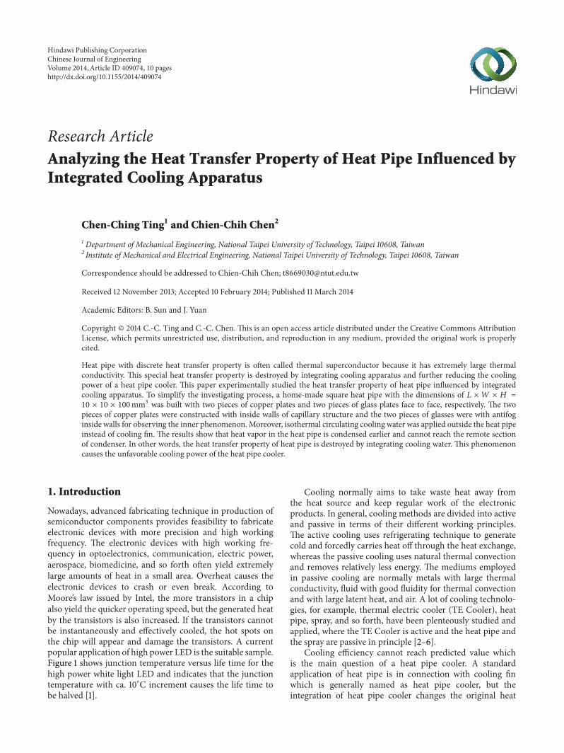
Nowadays, advanced fabricating technique in production ofsemiconductor components provides feasibility to fabricateelectronic devices with more precision and high workingfrequency. The electronic devices with high working fre-quency in optoelectronics, communication, electric power,aerospace, biomedicine, and so forth often yield extremelylarge amounts of heat in a small area. Overheat causes theelectronic devices to crash or even break. According toMoore’s law issued by Intel, the more transistors in a chipalso yield the quicker operating speed, but the generated heatby the transistors is also increased. If the transistors cannotbe instantaneously and effectively cooled, the hot spots onthe chip will appear and damage the transistors. A currentpopular application of high power LED is the suitable sample.Figure 1 shows junction temperature versus life time for thehigh power white light LED and indicates that the junctiontemperature with ca. 10∘C increment causes the life time tobe halved [1].
Cooling normally aims to take waste heat away fromthe heat source and keep regular work of the electronicproducts. In general, cooling methods are divided into activeand passive in terms of their different working principles.The active cooling uses refrigerating technique to generatecold and forcedly carries heat off through the heat exchange,whereas the passive cooling uses natural thermal convectionand removes relatively less energy. The mediums employedin passive cooling are normally metals with large thermalconductivity, fluid with good fluidity for thermal convectionand with large latent heat, and air. A lot of cooling technolo-gies, for example, thermal electric cooler (TE Cooler), heatpipe, spray, and so forth, have been plenteously studied andapplied, where the TE Cooler is active and the heat pipe andthe spray are passive in principle [2–6].
Cooling efficiency cannot reach predicted value whichis the main question of a heat pipe cooler. A standardapplication of heat pipe is in connection with cooling finwhich is generally named as heat pipe cooler, but theintegration of heat pipe cooler changes the original heat
Hindawi Publishing CorporationChinese Journal of EngineeringVolume 2014, Article ID 409074, 10 pageshttp://dx.doi.org/10.1155/2014/409074
2 Chinese Journal of Engineering
35 40 45 50 55 600
10000
20000
30000
40000
50000
80000
Life
(hrs
)T-point temperature (∘C)
Figure 1: Junction temperature versus life time for the high power white light LED [1].
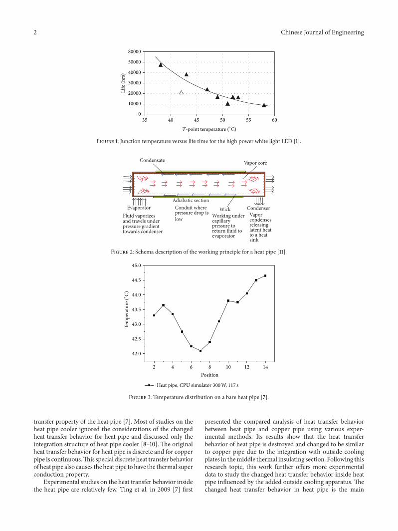
EvaporatorAdiabatic section
CondenserWickWorking undercapillarypressure toreturn fluid toevaporator
Vapor core Condensate
Fluid vaporizesand travels underpressure gradienttowards condenser
Conduit wherepressure drop islow
Vaporcondensesreleasinglatent heatto a heatsink
Figure 2: Schema description of the working principle for a heat pipe [11].
Tem
pera
ture
(∘ C)
42.0
42.5
43.0
43.5
44.0
44.5
45.0
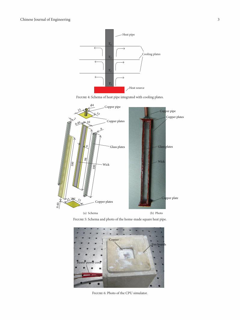
2 4 6 8 10 12 14
Position
Heat pipe, CPU simulator 300W, 117 s
Figure 3: Temperature distribution on a bare heat pipe [7].
transfer property of the heat pipe [7]. Most of studies on theheat pipe cooler ignored the considerations of the changedheat transfer behavior for heat pipe and discussed only theintegration structure of heat pipe cooler [8–10]. The originalheat transfer behavior for heat pipe is discrete and for copperpipe is continuous.This special discrete heat transfer behaviorof heat pipe also causes the heat pipe to have the thermal superconduction property.
Experimental studies on the heat transfer behavior insidethe heat pipe are relatively few. Ting et al. in 2009 [7] first
presented the compared analysis of heat transfer behaviorbetween heat pipe and copper pipe using various exper-imental methods. Its results show that the heat transferbehavior of heat pipe is destroyed and changed to be similarto copper pipe due to the integration with outside coolingplates in themiddle thermal insulating section. Following thisresearch topic, this work further offers more experimentaldata to study the changed heat transfer behavior inside heatpipe influenced by the added outside cooling apparatus. Thechanged heat transfer behavior in heat pipe is the main
Chinese Journal of Engineering 3
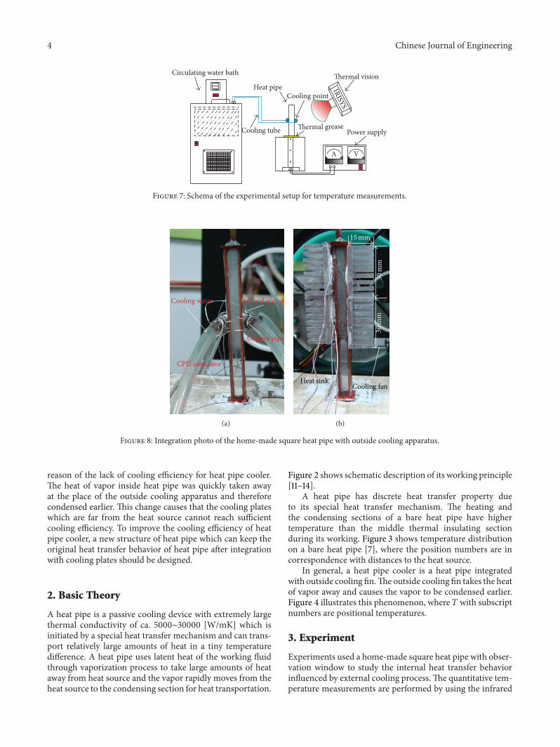
Heat source
Cooling plates
Heat pipe
T1
T2
T3
T4
Figure 4: Schema of heat pipe integrated with cooling plates.
Copper pipe
Copper plates
Glass plates
Wick
Copper plates15
1515
15
0.40
0.40
100100
98
10
6
6
2
𝜙4
(a) Schema
Copper pipe
Copper plates
Glass plates
Wick
Copper plate
(b) Photo
Figure 5: Schema and photo of the home-made square heat pipe.
CopperFire boards
Heater power cord
Figure 6: Photo of the CPU simulator.
4 Chinese Journal of Engineering
VA
Power supply
Heat pipe
Thermal greaseCooling tube
Cooling point
IRISYS
Thermal visionCirculating water bath
Figure 7: Schema of the experimental setup for temperature measurements.
Cooling water Thermal grease
Copper pipe
CPU simulator
(a)
15mm
30
mm
30
mm
Cooling fanHeat sink
(b)
Figure 8: Integration photo of the home-made square heat pipe with outside cooling apparatus.
reason of the lack of cooling efficiency for heat pipe cooler.The heat of vapor inside heat pipe was quickly taken awayat the place of the outside cooling apparatus and thereforecondensed earlier. This change causes that the cooling plateswhich are far from the heat source cannot reach sufficientcooling efficiency. To improve the cooling efficiency of heatpipe cooler, a new structure of heat pipe which can keep theoriginal heat transfer behavior of heat pipe after integrationwith cooling plates should be designed.
2. Basic Theory
A heat pipe is a passive cooling device with extremely largethermal conductivity of ca. 5000∼30000 [W/mK] which isinitiated by a special heat transfer mechanism and can trans-port relatively large amounts of heat in a tiny temperaturedifference. A heat pipe uses latent heat of the working fluidthrough vaporization process to take large amounts of heataway from heat source and the vapor rapidly moves from theheat source to the condensing section for heat transportation.
Figure 2 shows schematic description of its working principle[11–14].
A heat pipe has discrete heat transfer property dueto its special heat transfer mechanism. The heating andthe condensing sections of a bare heat pipe have highertemperature than the middle thermal insulating sectionduring its working. Figure 3 shows temperature distributionon a bare heat pipe [7], where the position numbers are incorrespondence with distances to the heat source.
In general, a heat pipe cooler is a heat pipe integratedwith outside cooling fin.The outside cooling fin takes the heatof vapor away and causes the vapor to be condensed earlier.Figure 4 illustrates this phenomenon, where 𝑇with subscriptnumbers are positional temperatures.
3. Experiment
Experiments used a home-made square heat pipe with obser-vation window to study the internal heat transfer behaviorinfluenced by external cooling process.The quantitative tem-perature measurements are performed by using the infrared
Chinese Journal of Engineering 5
T1
T2
T3
T4
T5
T6
1 cm
1 cm
2 cm
2 cm
2 cm
2 cm
Square heat pipe
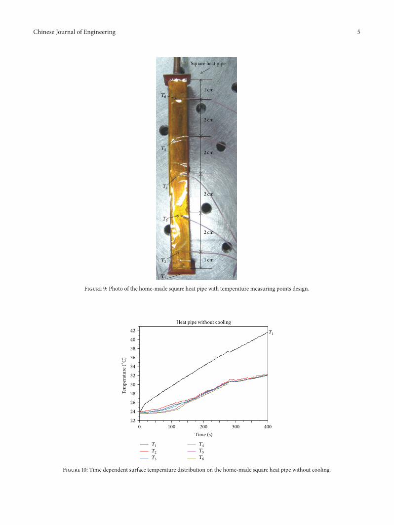
Figure 9: Photo of the home-made square heat pipe with temperature measuring points design.
T1
T1
T2
T3
T4
T5
T6
0 100 200 300 400
Time (s)
22
24
26
28
30
32
34
36
38
40
42
Tem
pera
ture
(∘ C)
Heat pipe without cooling
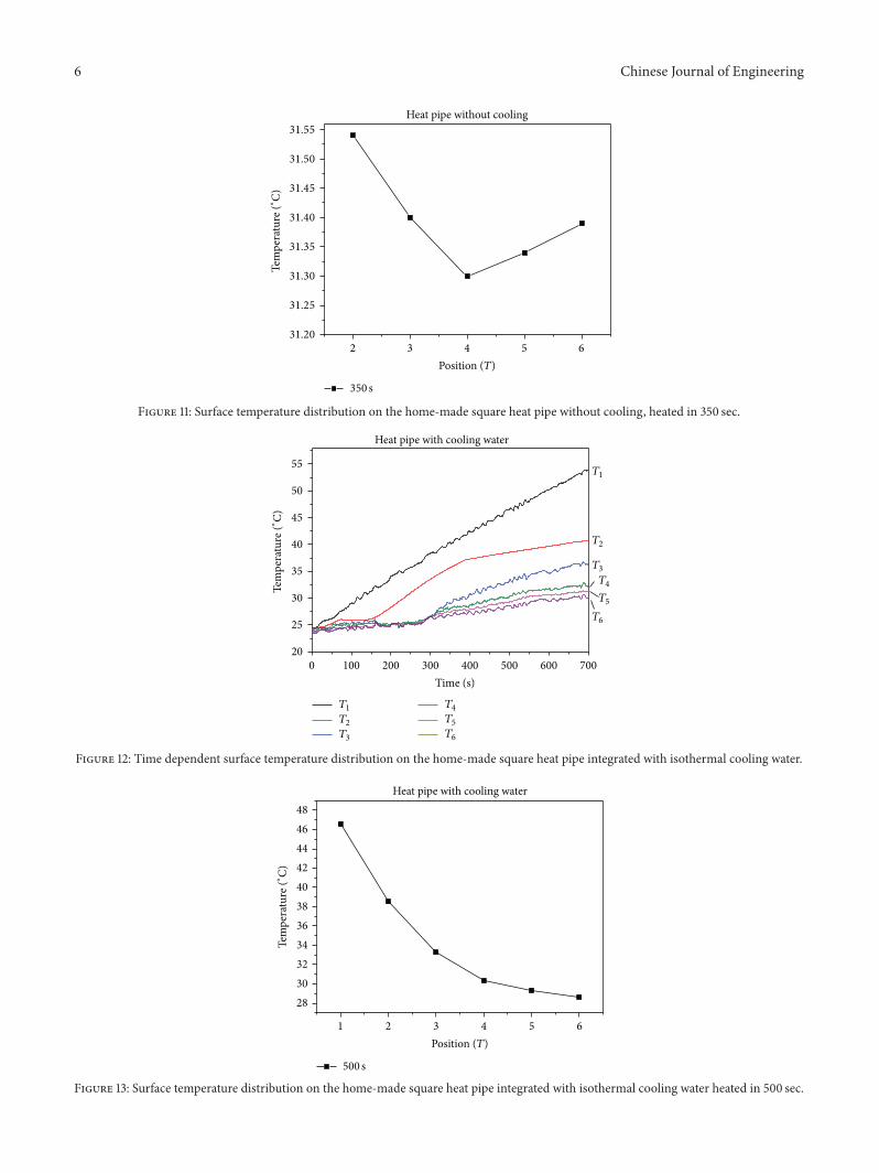
Figure 10: Time dependent surface temperature distribution on the home-made square heat pipe without cooling.
6 Chinese Journal of Engineering
Tem
pera
ture
(∘ C)
Heat pipe without cooling
350 s
31.30
31.35
31.20
31.25
31.40
31.45
31.50
31.55
2 3 4 5 6
Position (T)
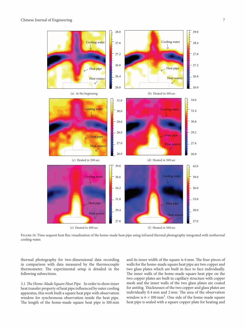
Figure 11: Surface temperature distribution on the home-made square heat pipe without cooling, heated in 350 sec.
T1
T2
T3
T4
T5
T6
0 100 200 300 700600500400
Time (s)
20
25
30
35
40
45
50
55
Tem
pera
ture
(∘ C)
T1
T2
T3
T4
T5
T6
Heat pipe with cooling water
Figure 12: Time dependent surface temperature distribution on the home-made square heat pipe integrated with isothermal cooling water.
Tem
pera
ture
(∘ C)
Heat pipe with cooling water
500 s
32
34
28
30
36
38
40
48
46
44
42
1 2 3 4 5 6
Position (T)
Figure 13: Surface temperature distribution on the home-made square heat pipe integrated with isothermal cooling water heated in 500 sec.
Chinese Journal of Engineering 7
Cooling water
Heat pipe
Heat source
26.0
26.4
26.8
27.2
27.6
28.0
(a) At the beginning
Cooling water
Heat pipe
Heat source
26.0
26.6
27.2
27.8
28.4
29.0
(b) Heated in 100 sec
Cooling water
Heat pipe
Heat source
26.0
27.0
28.0
29.0
30.0
31.0
(c) Heated in 200 sec
Cooling water
Heat pipe
Heat source
26.0
27.6
29.2
30.8
32.4
34.0
(d) Heated in 300 sec
Cooling water
Heat pipe
Heat source
27.0
29.4
31.8
34.2
36.6
39.0
(e) Heated in 400 sec
Cooling water
Heat pipe
Heat source
27.0
30.0
33.0
36.0
39.0
42.0
(f) Heated in 500 sec
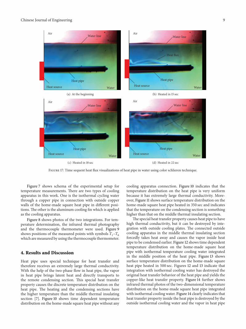
Figure 14: Time sequent heat flux visualization of the home-made heat pipe using infrared thermal photography integrated with isothermalcooling water.
thermal photography for two-dimensional data recordingin comparison with data measured by the thermocouplethermometer. The experimental setup is detailed in thefollowing subsections.
3.1.TheHome-Made SquareHeat Pipe. In order to show innerheat transfer property of heat pipe influenced by outer coolingapparatus, this work built a square heat pipe with observationwindow for synchronous observation inside the heat pipe.The length of the home-made square heat pipe is 100mm
and its inner width of the square is 6mm. The four pieces ofwalls for the home-made square heat pipe are two copper andtwo glass plates which are built in face to face individually.The inner walls of the home-made square heat pipe on thetwo copper plates are built in capillary structure with coppermesh and the inner walls of the two glass plates are coatedfor antifog.Thicknesses of the two copper and glass plates areindividually 0.4mm and 2mm. The area of the observationwindow is 6 × 100mm2. One side of the home-made squareheat pipe is sealed with a square copper plate for heating and

8 Chinese Journal of Engineering
T1
T2
T3
T4
T5
T6
0 100 250 350 65055045050 200 300 600500400
Time (s)
20
25
30
35
40
45
50
Tem
pera
ture
(∘ C)
T1
T2
T3
T4
T5T6
Heat pipe with cooling plates
Figure 15: Time dependent surface temperature distribution on the home-made square heat pipe integrated with aluminum cooling plates.
Tem
pera
ture
(∘ C)
Heat pipe with cooling plates
500 s
32
34
22
24
26
28
30
36
38
40
48
46
44
42
1 2 3 4 5 6
Position (T)
Figure 16: Surface temperature distribution on the home-made square heat pipe integrated with aluminum cooling plates heated in 500 sec.
the other side of the square heat pipe is connected with acopper pipe for vacuumization. Figure 5(a) shows schema ofthe square heat pipe and Figure 5(b) is its photo.
Table 1 shows specifications of the home-made squareheat pipe. In the manufacturing process, the two copperplates with copper mesh were sintered by 950∘C for 60mins.The filled working fluid in the heat pipe is deionized waterof 0.33 g for ca. 30 torr pressure at 24∘C. Its filling processfirst put deionized water of ca. 0.36 g into the home-madesquare heat pipe and then pumped to ca. 30 torr.The workingtemperature range of the home-made square heat pipe is 20∼60∘C.
3.2. The Temperature Measurements. A CPU simulator inaccordance with the ASTM D5470 standard was built as the
Table 1: Specifications of the home-made square heat pipe.
Devices Scale (mm) Material AmountCopper pipe 𝜙 = 4 Copper 1Glass plates 𝑊×𝐻 × 𝐷 = 6 × 100 × 2 SiO2 2Copper plates 𝑊×𝐻 × 𝐷 = 10 × 100 × 0.4 Copper 2
Wick 𝑊×𝐻 × 𝐷 = 6 × 98 × 0.1 Bronze 6(150 mesh)
Copper plates 𝑊×𝐻 × 𝐷 = 15 × 15 × 0.4 Copper 2
heat source in this work. Its heating area and maximumoutput power are individually 30 × 30mm2 and ca. 300W.Figure 6 is the photo of the CPU simulator.
Chinese Journal of Engineering 9
AirWater line
Heat pipe
WaterHeat source
(a) At the beginning
Air
Heat flux
Water line
Heat pipe
WaterHeat source
(b) Heated in 15 sec
AirWater line
Heat pipe
WaterHeat source
Heat flux
(c) Heated in 18 sec
AirWater line
Heat pipe
WaterHeat source
Heat flux
(d) Heated in 22 sec
Figure 17: Time sequent heat flux visualizations of heat pipe in water using color schlieren technique.
Figure 7 shows schema of the experimental setup fortemperature measurements. There are two types of coolingapparatus in this work. One is the isothermal cycling waterthrough a copper pipe in connection with outside copperwalls of the home-made square heat pipe in different posi-tions. The other is the aluminum cooling fin which is appliedas the cooling apparatus.
Figure 8 shows photos of the two integrations. For tem-perature determination, the infrared thermal photographyand the thermocouple thermometer were used. Figure 9shows positions of the measured points with symbols 𝑇
1–𝑇6
which aremeasured by using the thermocouple thermometer.
4. Results and Discussion
Heat pipe uses special technique for heat transfer andtherefore receives an extremely large thermal conductivity.With the help of the two-phase flow in heat pipe, the vaporin heat pipe brings latent heat and directly transports tothe remote condensing section. This special heat transferproperty causes the discrete temperature distribution on theheat pipe. The heating and the condensing sections havethe higher temperature than the middle thermal insulatingsection [7]. Figure 10 shows time dependent temperaturedistribution on the home-made square heat pipe without any
cooling apparatus connection. Figure 10 indicates that thetemperature distribution on the heat pipe is very uniformbecause it has extremely large thermal conductivity. More-over, Figure 11 shows surface temperature distribution on thehome-made square heat pipe heated in 350 sec and indicatesthat the temperature on the condensing section is somethinghigher than that on the middle thermal insulating section.
The special heat transfer property causes heat pipe to havehigh thermal conductivity, but it can be destroyed by inte-gration with outside cooling plates. The connected outsidecooling apparatus in the middle thermal insulating sectionforcedly takes heat away and causes the vapor inside heatpipe to be condensed earlier. Figure 12 shows time dependenttemperature distribution on the home-made square heatpipe with isothermal temperature cooling water integratedin the middle position of the heat pipe. Figure 13 showssurface temperature distribution on the home-made squareheat pipe heated in 500 sec. Figures 12 and 13 indicate thatintegration with isothermal cooling water has destroyed theoriginal heat transfer behavior of the heat pipe and yields thecopper-like heat transfer property. Figure 14 further showsinfrared thermal photos of the two-dimensional temperaturedistribution on the home-made square heat pipe integratedwith isothermal cooling water. Figure 14 clearly indicates thatheat transfer property inside the heat pipe is destroyed by theoutside isothermal cooling water and the vapor in heat pipe
10 Chinese Journal of Engineering
is condensed at the cooling position. The temperature on theremote condensing section is lower.
Figure 15 shows time dependent temperature distribu-tion on the home-made square heat pipe integrated withaluminum cooling plates and Figure 16 shows its surfacetemperature distribution on the home-made square heat pipeheated in 500 sec. In comparison with Figures 15 and 16, theresult shows good similarity. In other words, integration withcooling apparatus has destroyed the original heat transferbehavior of the heat pipe and yields the copper-like property.
Figures 17(a)–17(d) exhibit heat flux visualizations of heatpipe in water using color schlieren technique. Figures 17(a)–17(d) clearly show that the heat in themiddle thermal insulat-ing section is taken away due to the surrounding water whichserves as a cooling apparatus. This result gives good physicalexplanation of the forced thermal convection between heatpipe and the connected outside cooling apparatus in themiddle thermal insulating section.
5. Conclusion
Experimental study on heat transfer characterizations of heatpipe influenced by outside cooling apparatus has been suc-cessfully carried out. The results show that the heat transferbehavior of a bare heat pipe is discrete. In general, the heatingand the condensing sections of the bare heat pipe have highertemperature than the middle thermal insulating section.Integration with outside cooling apparatus has destroyedthe heat transfer property of a heat pipe. The changed heattransfer property of the heat pipe is similar to the copperpipe. To improve the cooling efficiency of the heat pipe cooler,a modified structure of heat pipe should be designed tokeep the original heat transfer behavior of heat pipe afterintegration with cooling plates.
Conflict of Interests
The authors declare that there is no conflict of interestsregarding the publication of this paper.
Acknowledgment
The authors would like to acknowledge the financial supportfrom the National Science Foundation of Taiwan, underGrant no. NSC98-2221-E-027-058.
References
[1] N. Narendran and Y. Gu, “Life of LED-based white lightsources,” IEEE/OSA Journal of Display Technology, vol. 1, no. 1,pp. 167–170, 2005.
[2] L. T. Yeh, “Review of heat transfer technologies in electronicequipment,” Journal of Electronic Packaging, vol. 117, no. 4, pp.333–339, 1995.
[3] M. S. El-Genk and H. Lianmin, “An experimental investigationof the transient response of a water heat pipe,” InternationalJournal of Heat andMass Transfer, vol. 36, no. 15, pp. 3823–3830,1993.
[4] R. Tummala, Fundamentals of Micro-Systems Packaging,McGraw-Hill, New York, NY, USA, 2002.
[5] S.-C. Lin, F.-S. Chuang, andC.-A. Chou, “Experimental study ofthe heat sink assembly with oblique straight fins,” ExperimentalThermal and Fluid Science, vol. 29, no. 5, pp. 591–600, 2005.
[6] W. Jia and H.-H. Qiu, “Experimental investigation of dropletdynamics and heat transfer in spray cooling,” ExperimentalThermal and Fluid Science, vol. 27, no. 7, pp. 829–838, 2003.
[7] C.-C. Ting, J.-N. Lee, and C.-C. Chen, “Heat transfer character-izations of heat pipe in comparisonwith copper pipe,” Journal ofHeat Transfer I, vol. 131, no. 3, Article ID 033109, pp. 1–6, 2009.
[8] A. Bejan and E. Sciubba, “The optimal spacing of parallel platescooled by forced convection,” International Journal of Heat andMass Transfer, vol. 35, no. 12, pp. 3259–3264, 1992.
[9] R.-H. Yeh and M. Chang, “Optimum longitudinal convectivefin arrays,” International Communications in Heat and MassTransfer, vol. 22, no. 3, pp. 445–460, 1995.
[10] C. A. Soule, Future Trends in Heat Sink Design, ElectronicsCooling, 2001.
[11] R. Viswanath, V. Wakharkar, A. Watwe, and V. Lebonheur,“Thermal performance challenges from silicon to systems,” IntelTechnology Journal, vol. Q3, 2000.
[12] Y.-H. Lin, S.-W. Kang, and H.-L. Chen, “Effect of silver nano-fluid on pulsating heat pipe thermal performance,” AppliedThermal Engineering, vol. 28, no. 11-12, pp. 1312–1317, 2008.
[13] S. Khandekar, Y.M. Joshi, and B.Mehta, “Thermal performanceof closed two-phase thermosyphon using nanofluids,” Interna-tional Journal of Thermal Sciences, vol. 47, no. 6, pp. 659–667,2008.
[14] L. L. Vasiliev, “Heat pipes in modern heat exchangers,” AppliedThermal Engineering, vol. 25, no. 1, pp. 1–19, 2005.

International Journal of
AerospaceEngineeringHindawi Publishing Corporationhttp://www.hindawi.com Volume 2014
RoboticsJournal of
Hindawi Publishing Corporationhttp://www.hindawi.com Volume 2014
Hindawi Publishing Corporationhttp://www.hindawi.com Volume 2014
Active and Passive Electronic Components
Control Scienceand Engineering
Journal of
Hindawi Publishing Corporationhttp://www.hindawi.com Volume 2014
International Journal of
RotatingMachinery
Hindawi Publishing Corporationhttp://www.hindawi.com Volume 2014
Hindawi Publishing Corporation http://www.hindawi.com
Journal ofEngineeringVolume 2014
Submit your manuscripts athttp://www.hindawi.com
VLSI Design
Hindawi Publishing Corporationhttp://www.hindawi.com Volume 2014
Hindawi Publishing Corporationhttp://www.hindawi.com Volume 2014
Shock and Vibration
Hindawi Publishing Corporationhttp://www.hindawi.com Volume 2014
Civil EngineeringAdvances in
Acoustics and VibrationAdvances in
Hindawi Publishing Corporationhttp://www.hindawi.com Volume 2014
Hindawi Publishing Corporationhttp://www.hindawi.com Volume 2014
Electrical and Computer Engineering
Journal of
Advances inOptoElectronics
Hindawi Publishing Corporation http://www.hindawi.com
Volume 2014
The Scientific World JournalHindawi Publishing Corporation http://www.hindawi.com Volume 2014
SensorsJournal of
Hindawi Publishing Corporationhttp://www.hindawi.com Volume 2014
Modelling & Simulation in EngineeringHindawi Publishing Corporation http://www.hindawi.com Volume 2014
Hindawi Publishing Corporationhttp://www.hindawi.com Volume 2014
Chemical EngineeringInternational Journal of Antennas and
Propagation
International Journal of
Hindawi Publishing Corporationhttp://www.hindawi.com Volume 2014
Hindawi Publishing Corporationhttp://www.hindawi.com Volume 2014
Navigation and Observation
International Journal of
Hindawi Publishing Corporationhttp://www.hindawi.com Volume 2014
DistributedSensor Networks
International Journal of