Embed Size (px)
Citation preview
Hindawi Publishing CorporationThe Scientific World JournalVolume 2013 Article ID 421410 10 pageshttpdxdoiorg1011552013421410
Research ArticleBalance Fatigue Design of Cast Steel Nodes inTubular Steel Structures
Libin Wang1 Hui Jin2 Haiwei Dong2 and Jing Li2
1 School of Civil Engineering Nanjing Forestry University Nanjing 210037 China2 Jiangsu Key Laboratory of Engineering Mechanics Southeast University Nanjing 210096 China
Correspondence should be addressed to Hui Jin jinhuiseueducn
Received 17 July 2013 Accepted 13 August 2013
Academic Editors C Garcia-Mateo M J Hua and S Lin
Copyright copy 2013 Libin Wang et al This is an open access article distributed under the Creative Commons Attribution Licensewhich permits unrestricted use distribution and reproduction in any medium provided the original work is properly cited
Cast steel nodes are being increasingly popular in steel structure joint application as their advanced mechanical performances andflexible forms This kind of joints improves the structural antifatigue capability observably and is expected to be widely used in thestructures with fatigue loadings Cast steel node joint consists of two parts casting itself and the welds between the node and thesteel memberThe fatigue resistances of these two parts are very different the experiment results showed very clearly that the fatiguebehavior was governed by the welds in all tested configurationsThis paper focuses on the balance fatigue design of these two partsin a cast steel node joint using fracture mechanics and FEM The defects in castings are simulated by cracks conservatively Thefinal crack size is decided by the minimum of 90 of the wall thickness and the value deduced by fracture toughnessThe allowableinitial crack size could be obtained through the integral of Paris equation when the crack propagation life is considered equal tothe weld fatigue life therefore the two parts in a cast steel node joint will have a balance fatigue life
1 Introduction
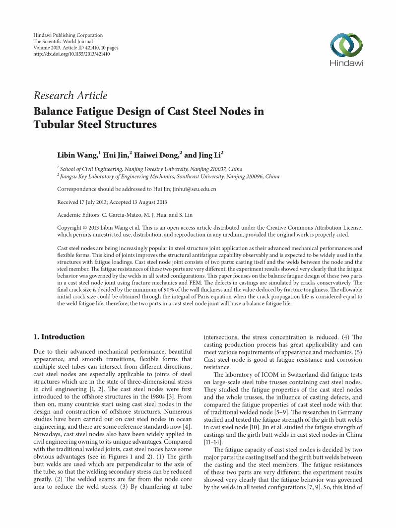
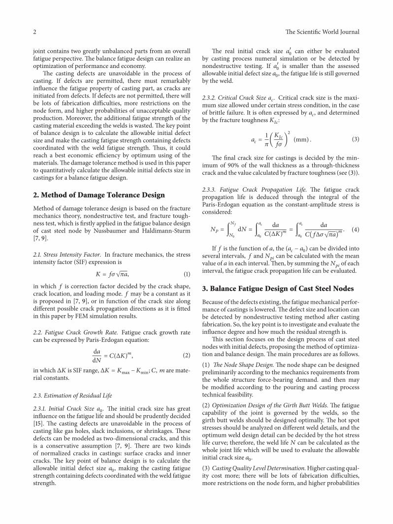
Due to their advanced mechanical performance beautifulappearance and smooth transitions flexible forms thatmultiple steel tubes can intersect from different directionscast steel nodes are especially applicable to joints of steelstructures which are in the state of three-dimensional stressin civil engineering [1 2] The cast steel nodes were firstintroduced to the offshore structures in the 1980s [3] Fromthen on many countries start using cast steel nodes in thedesign and construction of offshore structures Numerousstudies have been carried out on cast steel nodes in oceanengineering and there are some reference standards now [4]Nowadays cast steel nodes also have been widely applied incivil engineering owning to its unique advantages Comparedwith the traditional welded joints cast steel nodes have someobvious advantages (see in Figures 1 and 2) (1) The girthbutt welds are used which are perpendicular to the axis ofthe tube so that the welding secondary stress can be reducedgreatly (2) The welded seams are far from the node corearea to reduce the weld stress (3) By chamfering at tube
intersections the stress concentration is reduced (4) Thecasting production process has great applicability and canmeet various requirements of appearance and mechanics (5)Cast steel node is good at fatigue resistance and corrosionresistance
The laboratory of ICOM in Switzerland did fatigue testson large-scale steel tube trusses containing cast steel nodesThey studied the fatigue properties of the cast steel nodesand the whole trusses the influence of casting defects andcompared the fatigue properties of cast steel node with thatof traditional welded node [5ndash9] The researches in Germanystudied and tested the fatigue strength of the girth butt weldsin cast steel node [10] Jin et al studied the fatigue strength ofcastings and the girth butt welds in cast steel nodes in China[11ndash14]
The fatigue capacity of cast steel nodes is decided by twomajor parts the casting itself and the girth butt welds betweenthe casting and the steel members The fatigue resistancesof these two parts are very different the experiment resultsshowed very clearly that the fatigue behavior was governedby the welds in all tested configurations [7 9] So this kind of
2 The Scientific World Journal
joint contains two greatly unbalanced parts from an overallfatigue perspective The balance fatigue design can realize anoptimization of performance and economy
The casting defects are unavoidable in the process ofcasting If defects are permitted there must remarkablyinfluence the fatigue property of casting part as cracks areinitiated from defects If defects are not permitted there willbe lots of fabrication difficulties more restrictions on thenode form and higher probabilities of unacceptable qualityproduction Moreover the additional fatigue strength of thecasting material exceeding the welds is wasted The key pointof balance design is to calculate the allowable initial defectsize and make the casting fatigue strength containing defectscoordinated with the weld fatigue strength Thus it couldreach a best economic efficiency by optimum using of thematerialsThe damage tolerance method is used in this paperto quantitatively calculate the allowable initial defects size incastings for a balance fatigue design
2 Method of Damage Tolerance Design
Method of damage tolerance design is based on the fracturemechanics theory nondestructive test and fracture tough-ness test which is firstly applied in the fatigue balance designof cast steel node by Nussbaumer and Haldimann-Sturm[7 9]
21 Stress Intensity Factor In fracture mechanics the stressintensity factor (SIF) expression is
119870 = 119891120590radic120587119886 (1)
in which 119891 is correction factor decided by the crack shapecrack location and loading mode 119891 may be a constant as itis proposed in [7 9] or in function of the crack size alongdifferent possible crack propagation directions as it is fittedin this paper by FEM simulation results
22 Fatigue Crack Growth Rate Fatigue crack growth ratecan be expressed by Paris-Erdogan equation
d119886d119873
= 119862(Δ119870)119898
(2)
in which Δ119870 is SIF range Δ119870 = 119870max minus119870min 119862 119898 are mate-rial constants
23 Estimation of Residual Life
231 Initial Crack Size a0 The initial crack size has great
influence on the fatigue life and should be prudently decided[15] The casting defects are unavoidable in the process ofcasting like gas holes slack inclusions or shrinkages Thesedefects can be modeled as two-dimensional cracks and thisis a conservative assumption [7 9] There are two kindsof normalized cracks in castings surface cracks and innercracks The key point of balance design is to calculate theallowable initial defect size 119886
0 making the casting fatigue
strength containing defects coordinated with the weld fatiguestrength
The real initial crack size 1198861015840
0can either be evaluated
by casting process numeral simulation or be detected bynondestructive testing If 119886
1015840
0is smaller than the assessed
allowable initial defect size 1198860 the fatigue life is still governed
by the weld
232 Critical Crack Size a119888 Critical crack size is the maxi-
mum size allowed under certain stress condition in the caseof brittle failure It is often expressed by 119886
119888 and determined
by the fracture toughness 119870119868119888
119886119888=
1
120587(119870119868119888
119891120590)
2
(mm) (3)
The final crack size for castings is decided by the min-imum of 90 of the wall thickness as a through-thicknesscrack and the value calculated by fracture toughness (see (3))
233 Fatigue Crack Propagation Life The fatigue crackpropagation life is deduced through the integral of theParis-Erdogan equation as the constant-amplitude stress isconsidered
119873119875= int119873119891
1198730
d119873 = int119886119888
1198860
d119886119862(Δ119870)
119898= int119886119888
1198860
d119886119862(119891Δ120590radic120587119886)
119898 (4)
If 119891 is the function of 119886 the (119886119888minus 1198860) can be divided into
several intervals 119891 and119873119901119894can be calculated with the mean
value of 119886 in each intervalThen by summing the119873119901119894of each
interval the fatigue crack propagation life can be evaluated
3 Balance Fatigue Design of Cast Steel Nodes
Because of the defects existing the fatiguemechanical perfor-mance of castings is loweredThe defect size and location canbe detected by nondestructive testing method after castingfabrication So the key point is to investigate and evaluate theinfluence degree and how much the residual strength is
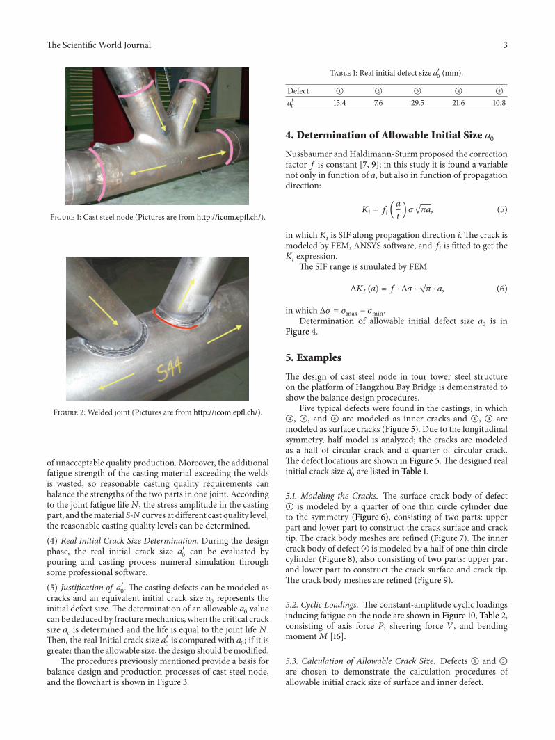
This section focuses on the design process of cast steelnodes with initial defects proposing themethod of optimiza-tion and balance design The main procedures are as follows(1) The Node Shape DesignThe node shape can be designedpreliminarily according to the mechanics requirements fromthe whole structure force-bearing demand and then maybe modified according to the pouring and casting processtechnical feasibility(2) Optimization Design of the Girth Butt Welds The fatiguecapability of the joint is governed by the welds so thegirth butt welds should be designed optimally The hot spotstresses should be analyzed on different weld details and theoptimum weld design detail can be decided by the hot stresslife curve therefore the weld life 119873 can be calculated as thewhole joint life which will be used to evaluate the allowableinitial crack size 119886
0
(3) CastingQuality Level DeterminationHigher casting qual-ity cost more there will be lots of fabrication difficultiesmore restrictions on the node form and higher probabilities
The Scientific World Journal 3
Figure 1 Cast steel node (Pictures are from httpicomepflch)
Figure 2 Welded joint (Pictures are from httpicomepflch)
of unacceptable quality production Moreover the additionalfatigue strength of the casting material exceeding the weldsis wasted so reasonable casting quality requirements canbalance the strengths of the two parts in one joint Accordingto the joint fatigue life 119873 the stress amplitude in the castingpart and thematerial S-N curves at different cast quality levelthe reasonable casting quality levels can be determined(4) Real Initial Crack Size Determination During the designphase the real initial crack size 119886
1015840
0can be evaluated by
pouring and casting process numeral simulation throughsome professional software(5) Justification of 1198861015840
0 The casting defects can be modeled as
cracks and an equivalent initial crack size 1198860represents the
initial defect size The determination of an allowable 1198860value
can be deduced by fracturemechanics when the critical cracksize 119886119888is determined and the life is equal to the joint life 119873
Then the real Initial crack size 11988610158400is compared with 119886
0 if it is
greater than the allowable size the design should bemodifiedThe procedures previously mentioned provide a basis for
balance design and production processes of cast steel nodeand the flowchart is shown in Figure 3
Table 1 Real initial defect size 11988610158400(mm)
Defect A B C D E
11988610158400
154 76 295 216 108
4 Determination of Allowable Initial Size 1198860
Nussbaumer and Haldimann-Sturm proposed the correctionfactor 119891 is constant [7 9] in this study it is found a variablenot only in function of 119886 but also in function of propagationdirection
119870119894= 119891119894(119886
119905) 120590radic120587119886 (5)
in which119870119894is SIF along propagation direction i The crack is
modeled by FEM ANSYS software and 119891119894is fitted to get the
119870119894expressionThe SIF range is simulated by FEM
Δ119870119868(119886) = 119891 sdot Δ120590 sdot radic120587 sdot 119886 (6)
in which Δ120590 = 120590max minus 120590minDetermination of allowable initial defect size 119886
0is in
Figure 4
5 Examples
The design of cast steel node in tour tower steel structureon the platform of Hangzhou Bay Bridge is demonstrated toshow the balance design procedures
Five typical defects were found in the castings in whichB C and E are modeled as inner cracks and A D aremodeled as surface cracks (Figure 5) Due to the longitudinalsymmetry half model is analyzed the cracks are modeledas a half of circular crack and a quarter of circular crackThe defect locations are shown in Figure 5 The designed realinitial crack size 1198861015840
0are listed in Table 1
51 Modeling the Cracks The surface crack body of defectA is modeled by a quarter of one thin circle cylinder dueto the symmetry (Figure 6) consisting of two parts upperpart and lower part to construct the crack surface and cracktip The crack body meshes are refined (Figure 7) The innercrack body of defectC is modeled by a half of one thin circlecylinder (Figure 8) also consisting of two parts upper partand lower part to construct the crack surface and crack tipThe crack body meshes are refined (Figure 9)
52 Cyclic Loadings The constant-amplitude cyclic loadingsinducing fatigue on the node are shown in Figure 10 Table 2consisting of axis force 119875 sheering force 119881 and bendingmoment119872 [16]
53 Calculation of Allowable Crack Size Defects A and Care chosen to demonstrate the calculation procedures ofallowable initial crack size of surface and inner defect
4 The Scientific World Journal
End
According to N
Casting technology simulation
According to fatigue life Ndetermine casting quality level
Weld detail design and fatigue life N determination
Y
Is technically feasible
Shape design of cast steel node
Start
N
Hot spot stress methodExperiment data of welds
Experiment data ofcasting materials
Professional software
Fracture mechanics
determine the real initial crack size a9984000
determine the allowable initial size a0
Compare a9984000 with a0
a9984000 lt a0
a9984000 ge a0
Figure 3 Procedures of optimization design of cast steel nodes
Table 2 Constant amplitude fatigue loads
Load case P (KN) V (KN) M (kN sdotm)
On Tube of Oslash 800 Case 1 Max 756391 24132 155521Case 2 Min minus736617 minus23456 minus151126
On Tube of Oslash 1600 Case 1 Max 2000222 49266 2091114Case 2 Min minus195673 minus48601 minus214845
531 Calculation of Allowable Initial Surface Crack Size ofDefect A The principal stress contour of the crack body isshown in Figure 11
DefectA locates at the edge of inner stiffener plate of thenode where the node wall thickness is 119905 = 45mm Five casesof different crack depth are analyzed by ANSYS that is 119886 =
15mm 20mm 25mm 30mm and 35mm in each case thecrack body is meshed along sixteen prorogation directions assymbol 120572 that is 120572 = 0
∘ 6∘ 90∘ See Figure 12In ANSYS the crack propagating path should be defined
a crack path is defined by nodes 1 2 3 4 5 for instance(Figure 13) The crack SIF is calculated as the average of SIFvalues at the nodes on the crack path
The expression of119870119868is [17]
119870119868=
1198641015840
4radic
120587
2119871[4 (]2+ ]4) minus ]3minus ]5] (7)
In which 1198641015840 = 119864(1 minus 1205832) (plane strain) 119864 is elasticmodulus 120583 is passion ratio ] is node displacement on thecrack path and 119871 is the length of the crack tip element
SIFs of five cases along sixteen direction path are shown inFigure 14 and a curve is fitted for each case to show the trendThe SIF values are obviously not constant their changingratio ranges are 63 sim 67 along the direction from 120572 = 0∘
to 120572 = 90∘ and 26 sim 410 along the crack depth from119886 = 15mm to 119886 = 35mm
The path of maximum SIF value is considered where 120572 =
0∘ (see in Figure 14) Along the path of 120572 = 0∘ the values of 119891at five crack depths are calculated through (5) and a quarticpolynomial is fitted (Figure 15)
The Scientific World Journal 5
(1) Determine the SIF expression
ANSYS
KI and f values at different aand directions
Correction factor expression f( at) fitting
Determine the expressionKI(a) = f(a) middot 120590 middot radic120587 middot a
(a)
(2) Determine the critical crack
ac
gt09t
af = 09t af = ac
le09t
ac =1120587(K119868119888f120590
)2
(b)
(3) Paris-Erdogan equation
Integration
Determine the fatigue life N
ΔK1(a) = f middot Δ120590 middot radic120587 middot a
N =
a119891
inta0
da
C middot [ΔK1(a)]m
Determine a0
(c)
Figure 4 Calculation of initial crack size
The expression of quartic polynomial is
119891(119886
119905) = 11486(
119886
119905)4
minus 37431(119886
119905)3
+ 47291(119886
119905)2
minus 29461 (119886
119905) + 10127
(8)
12
3
4
5
X
Y
Z
Figure 5 Node model and defect locations
By substitution of the data of wall thickness 119905 = 45mmthe expression of119870 in function of 119886 can be obtained through119891 fitting
119870119868= 120590radic120587 (2801036427119886
45
minus 41076543211988635
+ 2335358011988625
minus 65468911988615
+1012711988605
)
(9)
The casting material used in the steel tower structureat Hangzhou Bay is GS-20Mn5V and there is no fatigueand fracture data available for reference As the elementcompositions and mechanical properties of GS-Mn5V aresimilar to ZG20SiMn (Chinese Steel Grade) [18] the materialparameters of ZG20SiMn in [19] are used approximately119862 =
225510minus13 119898 = 39917 The critical 119869 integral of ZG20SiMn
is 119869 = 1026 (Nmm) so the fracture toughness can be de-duced in the case of plane strain
119870119868119888
= radic119869 sdot119864
1 minus 1205832= 1524 (MPradic119898) (10)
The allowable initial crack size of defect A is calculatedfollowing the flowchart (Figure 4) with the FEM analysisresults the result is 119886
0= 276mm and the designed real crack
size is 11988610158400= 154mm so the casting strength is satisfied
532 Calculation ofAllowable Initial InnerCrack Size ofDefectC The principal stress contour of the crack body is shownin Figure 16
DefectC locates at the inner of the node where the hor-izontal node thickness along the crack propagation directionis 119905 = 800mm Five cases of different crack depth are analyzedby ANSYS that is 119886 = 25mm 30mm 35mm 40mm and45mm In each case the crack body is meshed along thirteenprorogation directions as symbol 120572 that is 120572 = 0
∘ 15∘ 180∘ See Figure 17
6 The Scientific World Journal
Crack surface Crack tip
X
Y
Z
Figure 6 Surface crack body
X
Y
Z
Figure 7 Refined surface crack body meshes
Table 3 Results of five defects
Defect Crack pathWall
thickness 119905(mm)
1205720(mm) 1205721015840
0(mm) 120572
0119905 ()
A 120572 = 0∘ 45 276 154 61
B 120572 = 90∘ 35 233 76 67C 120572 = 180∘ 800 2213 295 28D 120572 = 0∘ 86 37 216 43E 120572 = 180
∘ 45 179 108 40
SIF values of five cases along thirteen direction paths areshown in Figure 18 and a curve is fitted for each case to showthe trendThe SIF value changing ratio ranges are 21 sim 44along the direction from 120572 = 0∘ to 120572 = 180∘ and 23 sim 47along the crack depth from 119886 = 25mm to 119886 = 45mm
The path of maximum SIF value is considered where 120572 =
180∘ (see in Figure 18) The fitting quartic polynomials are
shown in Figure 19One has
119891(119886
119905) = 30037(
119886
119905)4
minus 59051(119886
119905)3
+ 45707(119886
119905)2
minus 17529 (119886
119905) + 04142
(11)
By substitution of the data of thickness 119905 = 800mm theexpression of 119870 in function of 119886 is
119870119868= 120590radic120587 (733325195119886
45
minus 11533411988635
+714211988625
minus 21911988615
+ 0414211988605
)
(12)
the allowable initial crack size of defect C is calculatedfollowing the flowchart (Figure 4) with the FEM analysisresults the result is 119886
0= 2213mm and the designed real
crack size is 11988610158400= 295mm so the casting strength is satisfied
533 Results of Five Defects The results of five defects arelisted in Table 3 the ratio ranges of allowable initial defectsize to wall thickness are from 28 to 67 the max-ratiohappens at the thinnest wall thickness location and the min-ratio happens at the thickest inner node thickness locationTheminimum allowable initial defect locates at defectC andthe maximum allowable defect locates at defectB
It is shown that the present design with five defectssatisfies the strength demand and the results and conclusionscan be referenced for further design improvement
6 Conclusions
This paper focuses on the balance fatigue design of the twoparts in a cast steel node joint using fracture mechanics andFEM the key point in the procedures is how to calculate
The Scientific World Journal 7
Crack surface
Crack tip
X
Y
Z
Figure 8 Inner crack body
X
Y
Z
Figure 9 Refined inner crack body meshes
V1 P1 V2P2
M1 M2
empty800 empty1600
Figure 10 Loads on node
8 The Scientific World Journal
ANSYS 90Nodal solutionSub = 1Time = 1S1 (AVG)PowergraphicsEFACET = 1AVRES = MatDMX = 0874E minus 05SMN = minus137149SMX = 0223E + 08
minus1371490236E + 070486E + 070735E + 070985E + 070123E + 080148E + 080173E + 080198E + 080223E + 08
MNMX
Figure 11 Principal stress contour of crack bodyA
120572
a
a
y
Crack frontFree side
Figure 12 Prorogation directions
1
23
45
r
x u
y
120579
Figure 13 Crack path defined in ANSYS
the allowable initial equivalent crack size the following mainconclusions can be drawn
(1) The allowable existence of reasonable initial defectsmake the castings fatigue strength coordinated withthe weld fatigue strength to realize a balance designavoiding the material strength waste
(2) Casting defects can be equivalently treated as cracksand simulated by FEM software fracture module
(3) The engineering example shows the ratio of allowableinitial defect size to node thickness ranges from 28to 67 in which the high ratio may not be allowedwithout this balance design concept
0 20 40 60 80 100120572
04
05
06
07
08
09
a = 15mma = 20mma = 25mm
a = 30mma = 35mm
K1(times10
6N
middotmminus32)
Figure 14 SIF fitting of defectA
02
025
03
035
04
045
0 02 04 06 08 1at
f(at)
Figure 15 Fitting curve of 119891 at the path of 120572 = 0∘
(4) The crack SIF values shown in the fracture mechanicsimulation results are obviously not constant itdepends on the crack depth and crack propagationdirection and their changing ratio can be up to 410the SIF accuracy will seriously affect the fracture
The Scientific World Journal 9
MNMX
ANSYS 90Nodal solution
Sub = 1Time = 1
Step = 1
S1 (AVG)PowergraphicsEFACET = 1AVRES = MatDMX = 0248E minus 04SMN = minus123647SMX = 0115E + 08
minus1236470117E + 070246E + 070375E + 070504E + 070633E + 070762E + 070891E + 070102E + 080115E + 08
Figure 16 Principal stress contour of crack bodyC
120572
a
y
a
Crack frontFree side
Figure 17 Prorogation directions
a = 25mma = 30mma = 35mm
a = 40mma = 45mm
0 20 40 60 80 100 120 140 160 180120572
018
02
022
024
026
028
03
032
034
036
K1(times10
4N
middotmminus32)
Figure 18 SIF fitting of defectC
results so whether the SIF can be simplified as a con-stant correction factor or not should be determinedcarefully by a given requisite degree of accuracy
ar
f(ar)
012
013
014
015
016
017
002 003 004 005 006
Figure 19 Fitting curve of 119891at the path of 120572 = 180∘
(5) The node has distinct different fatigue capabilitiesunder some influences for example locations direc-tions and loading conditions For the fatigue sensitiveones it is important to estimate the defect propagat-ing direction and the range of SIF Δ119870 correctly
Conflict of Interests
The authors declare that there is no conflict of interestsregarding the publication of this paper
Acknowledgments
The work reported is supported by National Natural Sci-ence Foundation of China (51108075) The Natural ScienceFoundation of Jiangsu Province (BK2011613) Science andTechnology Project of the Ministry of Housing and Urban-Rural Development (2010-K2-7) and A Project Funded bythe Priority Academic Program Development of JiangsuHigher Education Institutions
10 The Scientific World Journal
References
[1] J C de Oliveira SWillibald J A Packer C Christopoulos andT Verhey ldquoCast steel nodes in tubular constructionmdashCanadianexperiencerdquo in Proceedings of the 11th International Symposiumand IIW International Conference on Tubular Structures pp523ndash529 Quebec City Canada September 2006
[2] H Schober ldquoSteel castings in architecture and engineeringrdquoModern Steel Construction vol 43 no 4 pp 65ndash72 2003
[3] A Ma and J V Sharp ldquoFatigue design of cast steel nodes inoffshore structures based on research datardquo in Proceedings of theInstitution of Civil Engineers Water Maritime and Energy pp112ndash126 June 1997
[4] DNV-RP-203 fatigue design of offshore structures April 2010[5] A Nussbaumer ldquoDefect tolerances of steel castings in bridge
structuresrdquo Report Scientifique ICOM Project IC 438 2001ndash2005
[6] A Schumacher S Sturm S Walbridge A Nussbaumer andM A Hirt ldquoFatigue design of bridges with welded circularhollow sectionsrdquo Rapport ICOM 489E ICOM Laboratoire dela construction metallique Lausanne Switzerland 2003
[7] A Nussbaumer S C Haldimann-Sturm and A SchumacherldquoFatigue of bridge joints using welded tubes or cast steel nodesolutionsrdquo in Proceedings of the 11th International Symposiumand IIW International Conference on Tubular Structures pp 56ndash63 Quebec City Canada September 2006
[8] S Haldimann-Sturm andA Nussbaumer ldquoTubular bridges andthe fatigue design of their jointsrdquo in Proceedings of the EurosteelConference on Steel and Composite Structures pp 45ndash52 June2005
[9] S C Haldimann-Sturm and A Nussbaumer ldquoFatigue designof cast steel nodes in tubular bridge structuresrdquo InternationalJournal of Fatigue vol 30 no 3 pp 528ndash537 2008
[10] M Veselcic S Herion and R Puthli ldquoSelection of butt-weldedconnections for joints between tubulars and cast steel nodesunder fatigue loadingrdquo in Proceedings of the 11th InternationalSymposium and IIW International Conference on Tubular Struc-tures pp 528ndash535 Quebec City Canada September 2006
[11] H Jin J Li and A Li ldquoChecking calculation of fatigue strengthfor cast steel joints of offshore tour tower under wave loadsrdquoJournal of Southwest Jiaotong University vol 45 no 5 pp 692ndash697 2010
[12] H Jin J Li Q Zhang and H Wang ldquoApplication of hot spotstress method to fatigue life evaluation of girth butt welds ofcast steel noderdquo Journal of Tongji University vol 37 no 1 pp20ndash25 2009
[13] H Jin Q Zhang and H Wang ldquoCheck on fatigue strength ofmembers for cast steel noderdquo Steel Construction vol 23 no 112pp 17ndash21 2008
[14] J Ge and H Jin ldquoFatigue life evaluation and detail design forgirth butt welds of cast steel noderdquo Steel Construction vol 23no 112 pp 26ndash31 2008 (Chinese)
[15] W Yao Analysis of Structural Fatigue Life National DefenceIndustry Press Peking China 2003 (Chinese)
[16] J Li Fatigue properties and optimization design of cast steelnodes [MS thesis] Mechanic Engineering Major in SoutheastUniversity Nanjing China 2010 (Chinese)
[17] D Xie Q Qian and C Li Numerical Calculation Method ofFracture Mechanics and Its Application in Engineering Sciencepress Peking china 2009 (Chinese)
[18] Z Yang and L Shen ldquoResearch and practice of weldingtechnology of GS-20Mn5V cast steel noderdquo Journal of ModernWelding vol 57 no 9 pp 45ndash46 2004 (Chinese)
[19] Manual of Mechanical Engineering Material Properties Edito-rial board Manual of Mechanical Engineering Material Proper-ties Machinery Industry Press Peking China 1994 (Chinese)
International Journal of
AerospaceEngineeringHindawi Publishing Corporationhttpwwwhindawicom Volume 2014
RoboticsJournal of
Hindawi Publishing Corporationhttpwwwhindawicom Volume 2014
Hindawi Publishing Corporationhttpwwwhindawicom Volume 2014
Active and Passive Electronic Components
Control Scienceand Engineering
Journal of
Hindawi Publishing Corporationhttpwwwhindawicom Volume 2014
International Journal of
RotatingMachinery
Hindawi Publishing Corporationhttpwwwhindawicom Volume 2014
Hindawi Publishing Corporation httpwwwhindawicom
Journal ofEngineeringVolume 2014
Submit your manuscripts athttpwwwhindawicom
VLSI Design
Hindawi Publishing Corporationhttpwwwhindawicom Volume 2014
Hindawi Publishing Corporationhttpwwwhindawicom Volume 2014
Shock and Vibration
Hindawi Publishing Corporationhttpwwwhindawicom Volume 2014
Civil EngineeringAdvances in
Acoustics and VibrationAdvances in
Hindawi Publishing Corporationhttpwwwhindawicom Volume 2014
Hindawi Publishing Corporationhttpwwwhindawicom Volume 2014
Electrical and Computer Engineering
Journal of
Advances inOptoElectronics
Hindawi Publishing Corporation httpwwwhindawicom
Volume 2014
The Scientific World JournalHindawi Publishing Corporation httpwwwhindawicom Volume 2014
SensorsJournal of
Hindawi Publishing Corporationhttpwwwhindawicom Volume 2014
Modelling amp Simulation in EngineeringHindawi Publishing Corporation httpwwwhindawicom Volume 2014
Hindawi Publishing Corporationhttpwwwhindawicom Volume 2014
Chemical EngineeringInternational Journal of Antennas and
Propagation
International Journal of
Hindawi Publishing Corporationhttpwwwhindawicom Volume 2014
Hindawi Publishing Corporationhttpwwwhindawicom Volume 2014
Navigation and Observation
International Journal of
Hindawi Publishing Corporationhttpwwwhindawicom Volume 2014
DistributedSensor Networks
International Journal of
2 The Scientific World Journal
joint contains two greatly unbalanced parts from an overallfatigue perspective The balance fatigue design can realize anoptimization of performance and economy
The casting defects are unavoidable in the process ofcasting If defects are permitted there must remarkablyinfluence the fatigue property of casting part as cracks areinitiated from defects If defects are not permitted there willbe lots of fabrication difficulties more restrictions on thenode form and higher probabilities of unacceptable qualityproduction Moreover the additional fatigue strength of thecasting material exceeding the welds is wasted The key pointof balance design is to calculate the allowable initial defectsize and make the casting fatigue strength containing defectscoordinated with the weld fatigue strength Thus it couldreach a best economic efficiency by optimum using of thematerialsThe damage tolerance method is used in this paperto quantitatively calculate the allowable initial defects size incastings for a balance fatigue design
2 Method of Damage Tolerance Design
Method of damage tolerance design is based on the fracturemechanics theory nondestructive test and fracture tough-ness test which is firstly applied in the fatigue balance designof cast steel node by Nussbaumer and Haldimann-Sturm[7 9]
21 Stress Intensity Factor In fracture mechanics the stressintensity factor (SIF) expression is
119870 = 119891120590radic120587119886 (1)
in which 119891 is correction factor decided by the crack shapecrack location and loading mode 119891 may be a constant as itis proposed in [7 9] or in function of the crack size alongdifferent possible crack propagation directions as it is fittedin this paper by FEM simulation results
22 Fatigue Crack Growth Rate Fatigue crack growth ratecan be expressed by Paris-Erdogan equation
d119886d119873
= 119862(Δ119870)119898
(2)
in which Δ119870 is SIF range Δ119870 = 119870max minus119870min 119862 119898 are mate-rial constants
23 Estimation of Residual Life
231 Initial Crack Size a0 The initial crack size has great
influence on the fatigue life and should be prudently decided[15] The casting defects are unavoidable in the process ofcasting like gas holes slack inclusions or shrinkages Thesedefects can be modeled as two-dimensional cracks and thisis a conservative assumption [7 9] There are two kindsof normalized cracks in castings surface cracks and innercracks The key point of balance design is to calculate theallowable initial defect size 119886
0 making the casting fatigue
strength containing defects coordinated with the weld fatiguestrength
The real initial crack size 1198861015840
0can either be evaluated
by casting process numeral simulation or be detected bynondestructive testing If 119886
1015840
0is smaller than the assessed
allowable initial defect size 1198860 the fatigue life is still governed
by the weld
232 Critical Crack Size a119888 Critical crack size is the maxi-
mum size allowed under certain stress condition in the caseof brittle failure It is often expressed by 119886
119888 and determined
by the fracture toughness 119870119868119888
119886119888=
1
120587(119870119868119888
119891120590)
2
(mm) (3)
The final crack size for castings is decided by the min-imum of 90 of the wall thickness as a through-thicknesscrack and the value calculated by fracture toughness (see (3))
233 Fatigue Crack Propagation Life The fatigue crackpropagation life is deduced through the integral of theParis-Erdogan equation as the constant-amplitude stress isconsidered
119873119875= int119873119891
1198730
d119873 = int119886119888
1198860
d119886119862(Δ119870)
119898= int119886119888
1198860
d119886119862(119891Δ120590radic120587119886)
119898 (4)
If 119891 is the function of 119886 the (119886119888minus 1198860) can be divided into
several intervals 119891 and119873119901119894can be calculated with the mean
value of 119886 in each intervalThen by summing the119873119901119894of each
interval the fatigue crack propagation life can be evaluated
3 Balance Fatigue Design of Cast Steel Nodes
Because of the defects existing the fatiguemechanical perfor-mance of castings is loweredThe defect size and location canbe detected by nondestructive testing method after castingfabrication So the key point is to investigate and evaluate theinfluence degree and how much the residual strength is
This section focuses on the design process of cast steelnodes with initial defects proposing themethod of optimiza-tion and balance design The main procedures are as follows(1) The Node Shape DesignThe node shape can be designedpreliminarily according to the mechanics requirements fromthe whole structure force-bearing demand and then maybe modified according to the pouring and casting processtechnical feasibility(2) Optimization Design of the Girth Butt Welds The fatiguecapability of the joint is governed by the welds so thegirth butt welds should be designed optimally The hot spotstresses should be analyzed on different weld details and theoptimum weld design detail can be decided by the hot stresslife curve therefore the weld life 119873 can be calculated as thewhole joint life which will be used to evaluate the allowableinitial crack size 119886
0
(3) CastingQuality Level DeterminationHigher casting qual-ity cost more there will be lots of fabrication difficultiesmore restrictions on the node form and higher probabilities
The Scientific World Journal 3
Figure 1 Cast steel node (Pictures are from httpicomepflch)
Figure 2 Welded joint (Pictures are from httpicomepflch)
of unacceptable quality production Moreover the additionalfatigue strength of the casting material exceeding the weldsis wasted so reasonable casting quality requirements canbalance the strengths of the two parts in one joint Accordingto the joint fatigue life 119873 the stress amplitude in the castingpart and thematerial S-N curves at different cast quality levelthe reasonable casting quality levels can be determined(4) Real Initial Crack Size Determination During the designphase the real initial crack size 119886
1015840
0can be evaluated by
pouring and casting process numeral simulation throughsome professional software(5) Justification of 1198861015840
0 The casting defects can be modeled as
cracks and an equivalent initial crack size 1198860represents the
initial defect size The determination of an allowable 1198860value
can be deduced by fracturemechanics when the critical cracksize 119886119888is determined and the life is equal to the joint life 119873
Then the real Initial crack size 11988610158400is compared with 119886
0 if it is
greater than the allowable size the design should bemodifiedThe procedures previously mentioned provide a basis for
balance design and production processes of cast steel nodeand the flowchart is shown in Figure 3
Table 1 Real initial defect size 11988610158400(mm)
Defect A B C D E
11988610158400
154 76 295 216 108
4 Determination of Allowable Initial Size 1198860
Nussbaumer and Haldimann-Sturm proposed the correctionfactor 119891 is constant [7 9] in this study it is found a variablenot only in function of 119886 but also in function of propagationdirection
119870119894= 119891119894(119886
119905) 120590radic120587119886 (5)
in which119870119894is SIF along propagation direction i The crack is
modeled by FEM ANSYS software and 119891119894is fitted to get the
119870119894expressionThe SIF range is simulated by FEM
Δ119870119868(119886) = 119891 sdot Δ120590 sdot radic120587 sdot 119886 (6)
in which Δ120590 = 120590max minus 120590minDetermination of allowable initial defect size 119886
0is in
Figure 4
5 Examples
The design of cast steel node in tour tower steel structureon the platform of Hangzhou Bay Bridge is demonstrated toshow the balance design procedures
Five typical defects were found in the castings in whichB C and E are modeled as inner cracks and A D aremodeled as surface cracks (Figure 5) Due to the longitudinalsymmetry half model is analyzed the cracks are modeledas a half of circular crack and a quarter of circular crackThe defect locations are shown in Figure 5 The designed realinitial crack size 1198861015840
0are listed in Table 1
51 Modeling the Cracks The surface crack body of defectA is modeled by a quarter of one thin circle cylinder dueto the symmetry (Figure 6) consisting of two parts upperpart and lower part to construct the crack surface and cracktip The crack body meshes are refined (Figure 7) The innercrack body of defectC is modeled by a half of one thin circlecylinder (Figure 8) also consisting of two parts upper partand lower part to construct the crack surface and crack tipThe crack body meshes are refined (Figure 9)
52 Cyclic Loadings The constant-amplitude cyclic loadingsinducing fatigue on the node are shown in Figure 10 Table 2consisting of axis force 119875 sheering force 119881 and bendingmoment119872 [16]
53 Calculation of Allowable Crack Size Defects A and Care chosen to demonstrate the calculation procedures ofallowable initial crack size of surface and inner defect
4 The Scientific World Journal
End
According to N
Casting technology simulation
According to fatigue life Ndetermine casting quality level
Weld detail design and fatigue life N determination
Y
Is technically feasible
Shape design of cast steel node
Start
N
Hot spot stress methodExperiment data of welds
Experiment data ofcasting materials
Professional software
Fracture mechanics
determine the real initial crack size a9984000
determine the allowable initial size a0
Compare a9984000 with a0
a9984000 lt a0
a9984000 ge a0
Figure 3 Procedures of optimization design of cast steel nodes
Table 2 Constant amplitude fatigue loads
Load case P (KN) V (KN) M (kN sdotm)
On Tube of Oslash 800 Case 1 Max 756391 24132 155521Case 2 Min minus736617 minus23456 minus151126
On Tube of Oslash 1600 Case 1 Max 2000222 49266 2091114Case 2 Min minus195673 minus48601 minus214845
531 Calculation of Allowable Initial Surface Crack Size ofDefect A The principal stress contour of the crack body isshown in Figure 11
DefectA locates at the edge of inner stiffener plate of thenode where the node wall thickness is 119905 = 45mm Five casesof different crack depth are analyzed by ANSYS that is 119886 =
15mm 20mm 25mm 30mm and 35mm in each case thecrack body is meshed along sixteen prorogation directions assymbol 120572 that is 120572 = 0
∘ 6∘ 90∘ See Figure 12In ANSYS the crack propagating path should be defined
a crack path is defined by nodes 1 2 3 4 5 for instance(Figure 13) The crack SIF is calculated as the average of SIFvalues at the nodes on the crack path
The expression of119870119868is [17]
119870119868=
1198641015840
4radic
120587
2119871[4 (]2+ ]4) minus ]3minus ]5] (7)
In which 1198641015840 = 119864(1 minus 1205832) (plane strain) 119864 is elasticmodulus 120583 is passion ratio ] is node displacement on thecrack path and 119871 is the length of the crack tip element
SIFs of five cases along sixteen direction path are shown inFigure 14 and a curve is fitted for each case to show the trendThe SIF values are obviously not constant their changingratio ranges are 63 sim 67 along the direction from 120572 = 0∘
to 120572 = 90∘ and 26 sim 410 along the crack depth from119886 = 15mm to 119886 = 35mm
The path of maximum SIF value is considered where 120572 =
0∘ (see in Figure 14) Along the path of 120572 = 0∘ the values of 119891at five crack depths are calculated through (5) and a quarticpolynomial is fitted (Figure 15)
The Scientific World Journal 5
(1) Determine the SIF expression
ANSYS
KI and f values at different aand directions
Correction factor expression f( at) fitting
Determine the expressionKI(a) = f(a) middot 120590 middot radic120587 middot a
(a)
(2) Determine the critical crack
ac
gt09t
af = 09t af = ac
le09t
ac =1120587(K119868119888f120590
)2
(b)
(3) Paris-Erdogan equation
Integration
Determine the fatigue life N
ΔK1(a) = f middot Δ120590 middot radic120587 middot a
N =
a119891
inta0
da
C middot [ΔK1(a)]m
Determine a0
(c)
Figure 4 Calculation of initial crack size
The expression of quartic polynomial is
119891(119886
119905) = 11486(
119886
119905)4
minus 37431(119886
119905)3
+ 47291(119886
119905)2
minus 29461 (119886
119905) + 10127
(8)
12
3
4
5
X
Y
Z
Figure 5 Node model and defect locations
By substitution of the data of wall thickness 119905 = 45mmthe expression of119870 in function of 119886 can be obtained through119891 fitting
119870119868= 120590radic120587 (2801036427119886
45
minus 41076543211988635
+ 2335358011988625
minus 65468911988615
+1012711988605
)
(9)
The casting material used in the steel tower structureat Hangzhou Bay is GS-20Mn5V and there is no fatigueand fracture data available for reference As the elementcompositions and mechanical properties of GS-Mn5V aresimilar to ZG20SiMn (Chinese Steel Grade) [18] the materialparameters of ZG20SiMn in [19] are used approximately119862 =
225510minus13 119898 = 39917 The critical 119869 integral of ZG20SiMn
is 119869 = 1026 (Nmm) so the fracture toughness can be de-duced in the case of plane strain
119870119868119888
= radic119869 sdot119864
1 minus 1205832= 1524 (MPradic119898) (10)
The allowable initial crack size of defect A is calculatedfollowing the flowchart (Figure 4) with the FEM analysisresults the result is 119886
0= 276mm and the designed real crack
size is 11988610158400= 154mm so the casting strength is satisfied
532 Calculation ofAllowable Initial InnerCrack Size ofDefectC The principal stress contour of the crack body is shownin Figure 16
DefectC locates at the inner of the node where the hor-izontal node thickness along the crack propagation directionis 119905 = 800mm Five cases of different crack depth are analyzedby ANSYS that is 119886 = 25mm 30mm 35mm 40mm and45mm In each case the crack body is meshed along thirteenprorogation directions as symbol 120572 that is 120572 = 0
∘ 15∘ 180∘ See Figure 17
6 The Scientific World Journal
Crack surface Crack tip
X
Y
Z
Figure 6 Surface crack body
X
Y
Z
Figure 7 Refined surface crack body meshes
Table 3 Results of five defects
Defect Crack pathWall
thickness 119905(mm)
1205720(mm) 1205721015840
0(mm) 120572
0119905 ()
A 120572 = 0∘ 45 276 154 61
B 120572 = 90∘ 35 233 76 67C 120572 = 180∘ 800 2213 295 28D 120572 = 0∘ 86 37 216 43E 120572 = 180
∘ 45 179 108 40
SIF values of five cases along thirteen direction paths areshown in Figure 18 and a curve is fitted for each case to showthe trendThe SIF value changing ratio ranges are 21 sim 44along the direction from 120572 = 0∘ to 120572 = 180∘ and 23 sim 47along the crack depth from 119886 = 25mm to 119886 = 45mm
The path of maximum SIF value is considered where 120572 =
180∘ (see in Figure 18) The fitting quartic polynomials are
shown in Figure 19One has
119891(119886
119905) = 30037(
119886
119905)4
minus 59051(119886
119905)3
+ 45707(119886
119905)2
minus 17529 (119886
119905) + 04142
(11)
By substitution of the data of thickness 119905 = 800mm theexpression of 119870 in function of 119886 is
119870119868= 120590radic120587 (733325195119886
45
minus 11533411988635
+714211988625
minus 21911988615
+ 0414211988605
)
(12)
the allowable initial crack size of defect C is calculatedfollowing the flowchart (Figure 4) with the FEM analysisresults the result is 119886
0= 2213mm and the designed real
crack size is 11988610158400= 295mm so the casting strength is satisfied
533 Results of Five Defects The results of five defects arelisted in Table 3 the ratio ranges of allowable initial defectsize to wall thickness are from 28 to 67 the max-ratiohappens at the thinnest wall thickness location and the min-ratio happens at the thickest inner node thickness locationTheminimum allowable initial defect locates at defectC andthe maximum allowable defect locates at defectB
It is shown that the present design with five defectssatisfies the strength demand and the results and conclusionscan be referenced for further design improvement
6 Conclusions
This paper focuses on the balance fatigue design of the twoparts in a cast steel node joint using fracture mechanics andFEM the key point in the procedures is how to calculate
The Scientific World Journal 7
Crack surface
Crack tip
X
Y
Z
Figure 8 Inner crack body
X
Y
Z
Figure 9 Refined inner crack body meshes
V1 P1 V2P2
M1 M2
empty800 empty1600
Figure 10 Loads on node
8 The Scientific World Journal
ANSYS 90Nodal solutionSub = 1Time = 1S1 (AVG)PowergraphicsEFACET = 1AVRES = MatDMX = 0874E minus 05SMN = minus137149SMX = 0223E + 08
minus1371490236E + 070486E + 070735E + 070985E + 070123E + 080148E + 080173E + 080198E + 080223E + 08
MNMX
Figure 11 Principal stress contour of crack bodyA
120572
a
a
y
Crack frontFree side
Figure 12 Prorogation directions
1
23
45
r
x u
y
120579
Figure 13 Crack path defined in ANSYS
the allowable initial equivalent crack size the following mainconclusions can be drawn
(1) The allowable existence of reasonable initial defectsmake the castings fatigue strength coordinated withthe weld fatigue strength to realize a balance designavoiding the material strength waste
(2) Casting defects can be equivalently treated as cracksand simulated by FEM software fracture module
(3) The engineering example shows the ratio of allowableinitial defect size to node thickness ranges from 28to 67 in which the high ratio may not be allowedwithout this balance design concept
0 20 40 60 80 100120572
04
05
06
07
08
09
a = 15mma = 20mma = 25mm
a = 30mma = 35mm
K1(times10
6N
middotmminus32)
Figure 14 SIF fitting of defectA
02
025
03
035
04
045
0 02 04 06 08 1at
f(at)
Figure 15 Fitting curve of 119891 at the path of 120572 = 0∘
(4) The crack SIF values shown in the fracture mechanicsimulation results are obviously not constant itdepends on the crack depth and crack propagationdirection and their changing ratio can be up to 410the SIF accuracy will seriously affect the fracture
The Scientific World Journal 9
MNMX
ANSYS 90Nodal solution
Sub = 1Time = 1
Step = 1
S1 (AVG)PowergraphicsEFACET = 1AVRES = MatDMX = 0248E minus 04SMN = minus123647SMX = 0115E + 08
minus1236470117E + 070246E + 070375E + 070504E + 070633E + 070762E + 070891E + 070102E + 080115E + 08
Figure 16 Principal stress contour of crack bodyC
120572
a
y
a
Crack frontFree side
Figure 17 Prorogation directions
a = 25mma = 30mma = 35mm
a = 40mma = 45mm
0 20 40 60 80 100 120 140 160 180120572
018
02
022
024
026
028
03
032
034
036
K1(times10
4N
middotmminus32)
Figure 18 SIF fitting of defectC
results so whether the SIF can be simplified as a con-stant correction factor or not should be determinedcarefully by a given requisite degree of accuracy
ar
f(ar)
012
013
014
015
016
017
002 003 004 005 006
Figure 19 Fitting curve of 119891at the path of 120572 = 180∘
(5) The node has distinct different fatigue capabilitiesunder some influences for example locations direc-tions and loading conditions For the fatigue sensitiveones it is important to estimate the defect propagat-ing direction and the range of SIF Δ119870 correctly
Conflict of Interests
The authors declare that there is no conflict of interestsregarding the publication of this paper
Acknowledgments
The work reported is supported by National Natural Sci-ence Foundation of China (51108075) The Natural ScienceFoundation of Jiangsu Province (BK2011613) Science andTechnology Project of the Ministry of Housing and Urban-Rural Development (2010-K2-7) and A Project Funded bythe Priority Academic Program Development of JiangsuHigher Education Institutions
10 The Scientific World Journal
References
[1] J C de Oliveira SWillibald J A Packer C Christopoulos andT Verhey ldquoCast steel nodes in tubular constructionmdashCanadianexperiencerdquo in Proceedings of the 11th International Symposiumand IIW International Conference on Tubular Structures pp523ndash529 Quebec City Canada September 2006
[2] H Schober ldquoSteel castings in architecture and engineeringrdquoModern Steel Construction vol 43 no 4 pp 65ndash72 2003
[3] A Ma and J V Sharp ldquoFatigue design of cast steel nodes inoffshore structures based on research datardquo in Proceedings of theInstitution of Civil Engineers Water Maritime and Energy pp112ndash126 June 1997
[4] DNV-RP-203 fatigue design of offshore structures April 2010[5] A Nussbaumer ldquoDefect tolerances of steel castings in bridge
structuresrdquo Report Scientifique ICOM Project IC 438 2001ndash2005
[6] A Schumacher S Sturm S Walbridge A Nussbaumer andM A Hirt ldquoFatigue design of bridges with welded circularhollow sectionsrdquo Rapport ICOM 489E ICOM Laboratoire dela construction metallique Lausanne Switzerland 2003
[7] A Nussbaumer S C Haldimann-Sturm and A SchumacherldquoFatigue of bridge joints using welded tubes or cast steel nodesolutionsrdquo in Proceedings of the 11th International Symposiumand IIW International Conference on Tubular Structures pp 56ndash63 Quebec City Canada September 2006
[8] S Haldimann-Sturm andA Nussbaumer ldquoTubular bridges andthe fatigue design of their jointsrdquo in Proceedings of the EurosteelConference on Steel and Composite Structures pp 45ndash52 June2005
[9] S C Haldimann-Sturm and A Nussbaumer ldquoFatigue designof cast steel nodes in tubular bridge structuresrdquo InternationalJournal of Fatigue vol 30 no 3 pp 528ndash537 2008
[10] M Veselcic S Herion and R Puthli ldquoSelection of butt-weldedconnections for joints between tubulars and cast steel nodesunder fatigue loadingrdquo in Proceedings of the 11th InternationalSymposium and IIW International Conference on Tubular Struc-tures pp 528ndash535 Quebec City Canada September 2006
[11] H Jin J Li and A Li ldquoChecking calculation of fatigue strengthfor cast steel joints of offshore tour tower under wave loadsrdquoJournal of Southwest Jiaotong University vol 45 no 5 pp 692ndash697 2010
[12] H Jin J Li Q Zhang and H Wang ldquoApplication of hot spotstress method to fatigue life evaluation of girth butt welds ofcast steel noderdquo Journal of Tongji University vol 37 no 1 pp20ndash25 2009
[13] H Jin Q Zhang and H Wang ldquoCheck on fatigue strength ofmembers for cast steel noderdquo Steel Construction vol 23 no 112pp 17ndash21 2008
[14] J Ge and H Jin ldquoFatigue life evaluation and detail design forgirth butt welds of cast steel noderdquo Steel Construction vol 23no 112 pp 26ndash31 2008 (Chinese)
[15] W Yao Analysis of Structural Fatigue Life National DefenceIndustry Press Peking China 2003 (Chinese)
[16] J Li Fatigue properties and optimization design of cast steelnodes [MS thesis] Mechanic Engineering Major in SoutheastUniversity Nanjing China 2010 (Chinese)
[17] D Xie Q Qian and C Li Numerical Calculation Method ofFracture Mechanics and Its Application in Engineering Sciencepress Peking china 2009 (Chinese)
[18] Z Yang and L Shen ldquoResearch and practice of weldingtechnology of GS-20Mn5V cast steel noderdquo Journal of ModernWelding vol 57 no 9 pp 45ndash46 2004 (Chinese)
[19] Manual of Mechanical Engineering Material Properties Edito-rial board Manual of Mechanical Engineering Material Proper-ties Machinery Industry Press Peking China 1994 (Chinese)
International Journal of
AerospaceEngineeringHindawi Publishing Corporationhttpwwwhindawicom Volume 2014
RoboticsJournal of
Hindawi Publishing Corporationhttpwwwhindawicom Volume 2014
Hindawi Publishing Corporationhttpwwwhindawicom Volume 2014
Active and Passive Electronic Components
Control Scienceand Engineering
Journal of
Hindawi Publishing Corporationhttpwwwhindawicom Volume 2014
International Journal of
RotatingMachinery
Hindawi Publishing Corporationhttpwwwhindawicom Volume 2014
Hindawi Publishing Corporation httpwwwhindawicom
Journal ofEngineeringVolume 2014
Submit your manuscripts athttpwwwhindawicom
VLSI Design
Hindawi Publishing Corporationhttpwwwhindawicom Volume 2014
Hindawi Publishing Corporationhttpwwwhindawicom Volume 2014
Shock and Vibration
Hindawi Publishing Corporationhttpwwwhindawicom Volume 2014
Civil EngineeringAdvances in
Acoustics and VibrationAdvances in
Hindawi Publishing Corporationhttpwwwhindawicom Volume 2014
Hindawi Publishing Corporationhttpwwwhindawicom Volume 2014
Electrical and Computer Engineering
Journal of
Advances inOptoElectronics
Hindawi Publishing Corporation httpwwwhindawicom
Volume 2014
The Scientific World JournalHindawi Publishing Corporation httpwwwhindawicom Volume 2014
SensorsJournal of
Hindawi Publishing Corporationhttpwwwhindawicom Volume 2014
Modelling amp Simulation in EngineeringHindawi Publishing Corporation httpwwwhindawicom Volume 2014
Hindawi Publishing Corporationhttpwwwhindawicom Volume 2014
Chemical EngineeringInternational Journal of Antennas and
Propagation
International Journal of
Hindawi Publishing Corporationhttpwwwhindawicom Volume 2014
Hindawi Publishing Corporationhttpwwwhindawicom Volume 2014
Navigation and Observation
International Journal of
Hindawi Publishing Corporationhttpwwwhindawicom Volume 2014
DistributedSensor Networks
International Journal of
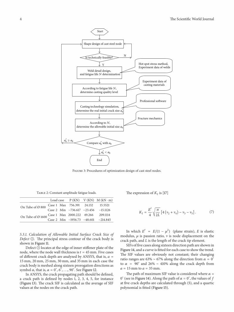
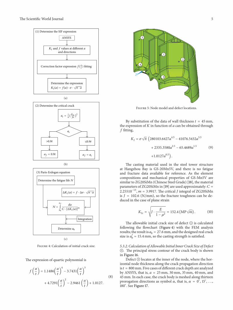
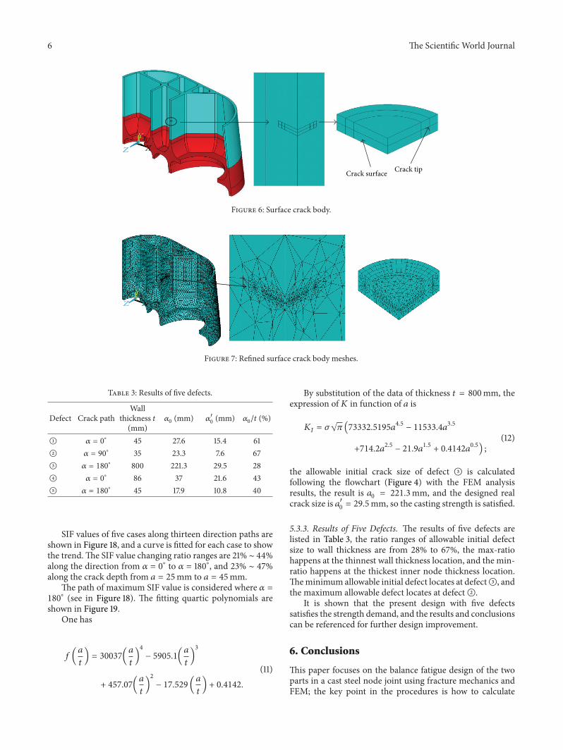
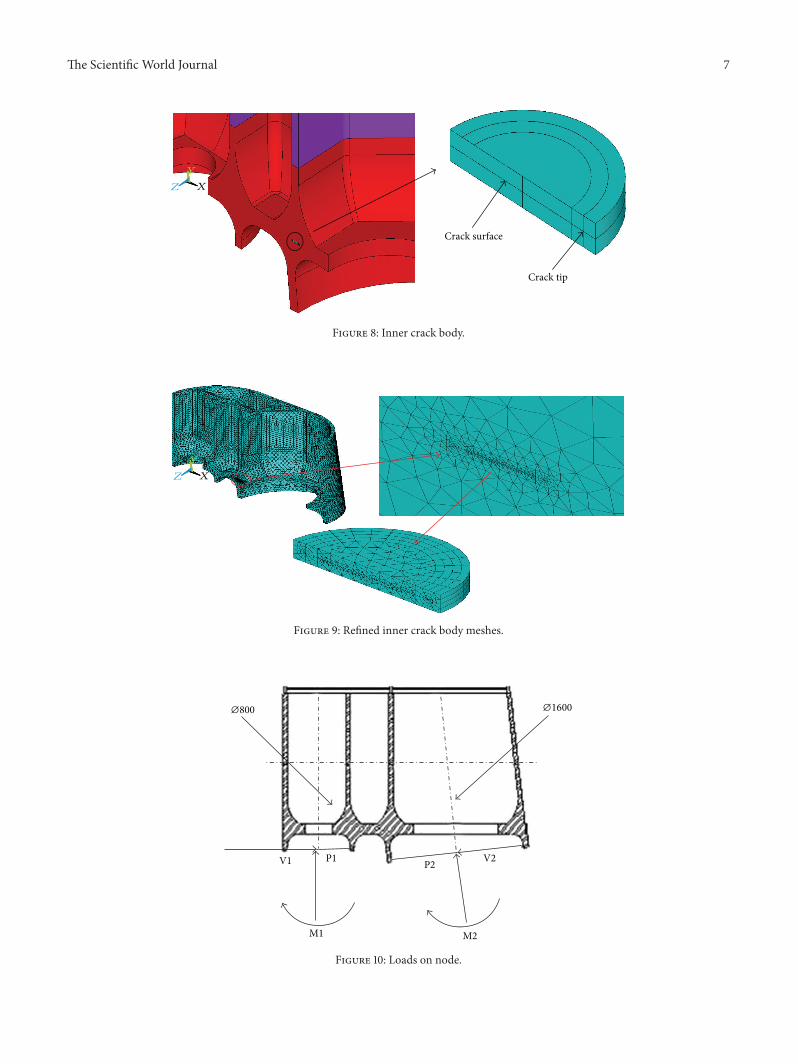
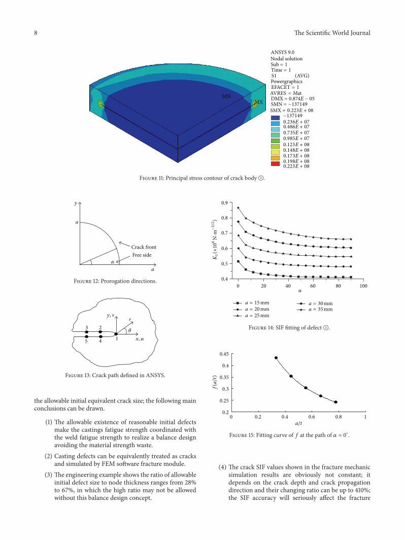
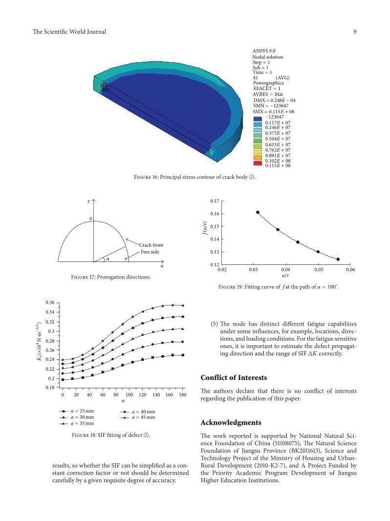
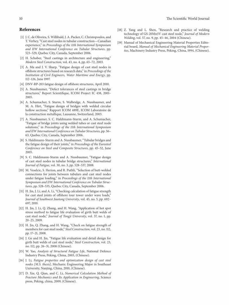

International Journal of
AerospaceEngineeringHindawi Publishing Corporationhttpwwwhindawicom Volume 2014
RoboticsJournal of
Hindawi Publishing Corporationhttpwwwhindawicom Volume 2014
Hindawi Publishing Corporationhttpwwwhindawicom Volume 2014
Active and Passive Electronic Components
Control Scienceand Engineering
Journal of
Hindawi Publishing Corporationhttpwwwhindawicom Volume 2014
International Journal of
RotatingMachinery
Hindawi Publishing Corporationhttpwwwhindawicom Volume 2014
Hindawi Publishing Corporation httpwwwhindawicom
Journal ofEngineeringVolume 2014
Submit your manuscripts athttpwwwhindawicom
VLSI Design
Hindawi Publishing Corporationhttpwwwhindawicom Volume 2014
Hindawi Publishing Corporationhttpwwwhindawicom Volume 2014
Shock and Vibration
Hindawi Publishing Corporationhttpwwwhindawicom Volume 2014
Civil EngineeringAdvances in
Acoustics and VibrationAdvances in
Hindawi Publishing Corporationhttpwwwhindawicom Volume 2014
Hindawi Publishing Corporationhttpwwwhindawicom Volume 2014
Electrical and Computer Engineering
Journal of
Advances inOptoElectronics
Hindawi Publishing Corporation httpwwwhindawicom
Volume 2014
The Scientific World JournalHindawi Publishing Corporation httpwwwhindawicom Volume 2014
SensorsJournal of
Hindawi Publishing Corporationhttpwwwhindawicom Volume 2014
Modelling amp Simulation in EngineeringHindawi Publishing Corporation httpwwwhindawicom Volume 2014
Hindawi Publishing Corporationhttpwwwhindawicom Volume 2014
Chemical EngineeringInternational Journal of Antennas and
Propagation
International Journal of
Hindawi Publishing Corporationhttpwwwhindawicom Volume 2014
Hindawi Publishing Corporationhttpwwwhindawicom Volume 2014
Navigation and Observation
International Journal of
Hindawi Publishing Corporationhttpwwwhindawicom Volume 2014
DistributedSensor Networks
International Journal of