Embed Size (px)
Citation preview
Hindawi Publishing CorporationMathematical Problems in EngineeringVolume 2013 Article ID 680376 17 pageshttpdxdoiorg1011552013680376
Research ArticleDecomposed Sliding Mode Control of the Drive with InteriorPermanent Magnet Synchronous Motor and Flexible Coupling
Jan Vittek1 and Sergey Ryvkin2
1 University of Zilina Univerzitna 1 010 26 Zilina Slovakia2 Trapeznikov Institute of Control Sciences Profsojuznaja 65 117 997 Moscow Russia
Correspondence should be addressed to Jan Vittek janvittekfelunizask
Received 14 February 2013 Revised 31 July 2013 Accepted 3 August 2013
Academic Editor Yuqiang Wu
Copyright copy 2013 J Vittek and S Ryvkin This is an open access article distributed under the Creative Commons AttributionLicense which permits unrestricted use distribution and reproduction in any medium provided the original work is properlycited
A decomposed sliding mode control of the drive with an interior permanent magnet synchronous motor and flexible couplingis presented Decomposition exploits principles of vector control to divide motor into channel for control of magnetic flux andchannel for control of torque separately Sliding mode control principles are exploited to keep demanded value of magnetic fluxand to control load angle in the presence of vibration modes and external disturbances To obtain continues voltage as a controlvariable a smoothing integrator follows signum function in both channels As a modification the switching governed by signumfunction is replaced by the high gain including rearrangement of the control system block diagram The simulations indicate thatthe control system yields the desired robustness and further investigations are recommended
1 Introduction
Fulfillment of the increasing quality requirements to theperformance of many industrial drives nowadays is notpossible in the presence of the elastic features of the driversquosmechanical parts Such features can cause torsion vibrationswhich decrease the drive dynamic accuracy and in somespecific cases can even lead to instability of the overall controlsystem Product degradation is usually a result of them Theproblem of torsional vibration elimination is prevalent notonly in high-power application such as rolling-mill drivesbut also conveyer and cage-host drives Today due to theprogress in power electronic and microprocessor systemsthat allow controlling the electromagnetic torque of motoralmost without any delay and expand a pass-band up to thefrequencies comparable to a resonance frequencies of thecontrolled plant mechanical parts the problem of torsionalvibrations appears also in many medium and low-powerapplications such as servo-drives throttle drives and robotarm drives including space applications [1ndash6]
It is well known that the classical PI controller is noteffective in controlling the plant with elastic joints Many
different control concepts that effectively damped torsionalvibrations have been proposed and developed for example[7 8] For instance additional feedback from selected statevariables of the two-mass system can effectively damp tor-sional vibrations [4]
In the case if the control plant parameters can changethe problem is getting more complicated andmany advancedcontrol concepts have been proposed as solution For exam-ple the solution based on the robust control theory exploitingthe 119867
infinis presented in [9] The genetic algorithm is used
to receive the estimates of control plant parameters TheModel Predictive Control is another tool that is used to solvethe above-mentioned control problemTheModel PredictiveControl generates an optimal control taking directly intoaccount all available andor estimated information aboutthe control variables control plant parameters and forexample the input and output constraints of the plant [10ndash12] However the real-time implementation of such control iscurrently limited because of need to solve complex optimiza-tion problem in the presence of complete information aboutall control variables and plant parameters
2 Mathematical Problems in Engineering
Different approaches depend on application of a sliding-mode control robustness of which is capable to eliminateinfluence of control plant parameters changes and also toeliminate external disturbances if these are presented in thecontrol system dynamics [13ndash16]
The main goal of this paper is to present the novel slidingmode control based control system for plant with elasticsconnections that combines robustness with chattering freecontrol while exploiting voltage source inverter (VSI)
11 Control Plant Model The control plant has three impor-tant parts
(i) VSI that feeds IPMSM(ii) Interior Permanent Magnet Synchronous Motor(iii) Elastic mechanical transmission for example a gear-
box with external load
Mathematical models of these plant parts are necessaryfor control system design therefore their description ispresented in the following
12 Voltage Source Inverter As it is known feed voltagescorresponding to the demanded operation mode of thesynchronous motor should be generated on its windingsA supplyline with three-phase voltages (119860 119861 119862) with fixedamplitude and frequency usually acts as the source of powerenergy Power converters are used to transform these voltagesinto three-phase supply voltages for a synchronous motor(119877 119878 119879) having a variable magnitude and frequency Three-phase power converters are built using power transistorsworking in relay mode [17]
The phase output voltage of the power converter rep-resents in this case a sequence of voltage impulses Thishigh frequency sequence is averaged in the synchronousmotor winding owing to its filtering propertyThe theoreticalbackground is based on Shannon-Kotelnikov or the samplingtheorem [18 19] This average voltage could be consideredas a continuous phase voltage on the synchronous motorwinding needed to solve the control problem Thus thephase output voltage of the power converter from the controlviewpoint has a dual character
(a) pulsemdashby nature(b) continuous averagemdashfor electric motor control
To realize the specified transformation of the three-phasevoltages widely the scheme of power transformation witha direct current link (Figure 1) is used In this case thethree-phase supply line voltages are rectified by means of athree-phase rectifier and smooth out by an output capacitorObtained constant voltage supplies an input of the three-phase VSI From DC link voltage inverter produces desiredthree-phase voltages of variable frequency and magnitude
The voltage source inverter [16] transforms a DC inputvoltage in three-phase variable voltages of a constant orvariable frequency andor amplitude To obtain the neededphase voltage the voltage transformation pulse method isused It is based on the application of a switch operationmode
T
S
R
C
B
A
Rectifier VSI
Uin
=
= sim
sim
Figure 1 Power converter with a direct current link
pR pS pT
KRUinKS KT
UR US UT
USO
URO
UTO
Figure 2 The simplified schema of the three-phase VSI bridge
of power semiconductor devices (switches)They connect anyoutput phase of the load to a source of constant voltage 119880in
One of themostly used VSI is the three-phase bridge withthe isolated neutral shown in Figure 2 It has a star connectedload with a parallel connection of three phases on-off powerswitches 119870
119895(119895 = 119877 119878 119879) A control signal 119901
119895(119901119895isin 0 1) of
each switch controls the connection of the VSI output phaseload either to a positive potential or to the negative one of theconstant input voltage 119880in
Thus depending on a control signal of each switch theoutput phase voltage 119880
1198950is equal at any moment to input
constant voltage119880in or zeroThe vector of VSI output voltageU119879 = (119880
120572 119880120573) in a fixed orthogonal coordinate system
(120572 120573) is defined by Clark transformation as
10038161003816100381610038161003816100381610038161003816
119880120572
119880120573
10038161003816100381610038161003816100381610038161003816
=2
3
1003816100381610038161003816100381610038161003816100381610038161003816100381610038161003816100381610038161003816
1 minus1
2minus1
2
0radic3
2minusradic3
2
1003816100381610038161003816100381610038161003816100381610038161003816100381610038161003816100381610038161003816
100381610038161003816100381610038161003816100381610038161003816100381610038161003816
119880119877119874
119880119878119874
119880119879119874
100381610038161003816100381610038161003816100381610038161003816100381610038161003816
(1)
where numerical factors of a transformation matrix aredirecting the phase load terminals (119877 119878 119879) As phase voltageshave relay character the voltage output vector U can accept
Mathematical Problems in Engineering 3
R
120572
120573
120593
S
T
Uref
U6(101)U5(001)
U4(011)
U3(010) U2(110)
U1(100)
2Uin3
12minus12
minusradic3
2
radic3
2
Figure 3 Vectors of VSI in complex plane
only eighth values two of them are zero 1198800and other six
119880119894(119894 = 1 6) are nonzero and create the tops of the regular
hexagon (Figure 3) Its symmetry axes are directed on thephase load terminals
The module of the above-mentioned six nonzero vectorsdepends on the load connection and on the value of the inputdc line voltage 119880in In the load connected as ldquostarrdquo circuitit is equal to 2119880in3 The combination of phase switches(119901119877 119901119878 119901119879) controls the possible vector of the output voltage
119880119894presented in Figure 3 The zero vectors correspond to two
combinations of the switch positions either all are connectedto positive potential (111) or to negative potential (000)
The VSI switch control providing the needed outputvoltage has two independent parts [20 21]
(i) the modulation law that defines the part of themodulation period in which the power switch isconnected either to the positive potential (119880in) or thenegative one (0)
(ii) the switching law that defines a sequence of switchingof phase switches on the modulation period
In this case each phase output voltage represents asequence of various duration squared impulses magnitude ofwhich is equal to 119880in that is the feed voltage A sequence ofthese impulses being averaged owing to filtering propertiesof the load forms a phase output voltage on the load creatinga control tool In analysis of the VSI operation and controlsystem synthesis it is therefore necessary to consider thedual character of an output voltage vector On one hand itis characterized at any moment by the instantaneous valuecaused by instantaneous positions of the power switches Onthe other hand owing to that the averaging properties of theload it possesses an average on the modulation period valuedefining the VSI feature is a part of an automatic controlsystem These problems will be also considered furtherduring the design of control system for the drive employingsynchronous motor
13 Interior Permanent Magnet SynchronousMotor The clas-sical mathematical model that considers the basic physical
features of the processes inside of the motor shown inFigure 4 received by standard assumptions is used for motordescription [13ndash15] In the frame of these assumptions themathematical description of IPMSM includes the followingthree groups of equations
(i) equations of electric balance in its windings(ii) equation of the electromagnetic torque developed by
the electric motor(iii) equation of mechanical movement (Newtonrsquos second
law for a rotary motion)
The third equation based on formula of mechanicalmovement is general for all electric motors and has thefollowing form
119869119889Ω
119889119905= 119872el minus119872 (2)
where 119869 is the moment of inertia of all rotational partsreduced to the shaft of rotor Ω is the rotor angular speed119905 is the current time and 119872el is the electromagnetic torquedeveloped by the motor 119872 = sum119872
119897(119865119894) is the sum of the
torques of the external forces enclosed to a rotorThe equations of electric balance based on Kirchhoff rsquos
second law and the equations of electromagnetic torque aredefined by the electric and magnetic circuits of the IPMSMand the physical processes inside of it In the case of IPMSMthe magnetic flux is created by permanent magnets locatedinside of the rotor Such placement of permanent magnetsgives to the rotor feature of the salient poles and the IPMSMhas a nonuniform air gapDue to nonuniformity of the air gapthe magnetic flux creates an additional (reluctance) torque
It is well known that mathematical description of theelectromechanical transformation of power in the IPMSMusing the actual phase currents and voltages as independentvariables is capable to describe the physical processes insideof the motor On the other hand such description is relativelycomplicated for analysis of the dynamical processes andresults in a system of nonlinear differential equations withperiodically changing coefficients due to change of rotorposition
The successful choice of transformation into axes (0 119889 119902)plays a fundamental role in the theory of synchronousmachines and the theory of automatic drives and clearlyproves the following statements First thanks to the rotatingcoordinates system connected to a rotor the differentialequations describing the synchronous motor dynamics haveconstant coefficients
Second orientation of a datum line 0 on the axis of rota-tion makes the differential equation independent regardingto a zero sequence current It must be emphasized that thezero sequence current does not participate in the creationof air gap magnetic field and it has no influence on theelectromechanical processes in the motor It creates only anadditional loading of windings and semiconductor devicesThe traditional connection of motor phase windings ldquostarrdquo orldquodeltardquo automatically provides cancellation of a zero sequencecurrent that is it eliminates additional thermal losses It leads
4 Mathematical Problems in Engineering
uB
S
A
q
d N
uC
uA
B
C
Figure 4 IPMSM
to simplification of mathematical description of synchronousmotor Elimination of differential equation for the zerosequence current reduces the system order In this case theconsidered three-phase synchronous motor is replaced by atwo-phase ldquoidealizedrdquo one (the generalized electric machine)which from the point of view of the electromagnetic processesrepresents the collector machine
The transformation from the three-phase coordinates sys-tem to the rotating two-phase system (0 119889 119902) is implementedvia a Park transformation matrix
119862 = radic2
3(cos 120574119860
cos 120574119861
cos 120574119862
minus sin 120574119860
minus sin 120574119861minus sin 120574
119862
) (3)
where 120574119895is an electric angle between a rotor axis119889 and a stator
phase axis 119895 (119895 = 119860 119861 119862) and radic23 is a factor for powerinvariance
The electric variables in a rotating system 119894119889 119894119902 119906119889 119906119902are
also connected to phase variables
119868 = 1198621198681015840
119880 = 1198621198801015840
(4)
where 119868119879 = (119894119889 119894119902) 1198681015840119879 = (119894
119860 119894119861 119894119862) 119880119879 = (119906
119889 119906119902) 1198801015840119879 =
(119906119860 119906119861 119906119862)
The equations of electric balance and the electromagneticmoment for IPMSM in the rotating frame are as follows
119889119894119889
119889119905=
1
119871119889
(minus119903119894119889+ 119871119902120596119894119902) +
1
119871119889
119906119889
119889119894119902
119889119905=
1
119871119902
(minus119903119894119902minus 119871119889120596119894119889minus Ψ119891120596) +
1
119871119902
119906119902
119872el =3
2119901 [Ψ119891+ (119871119889minus 119871119902) 119894119889] 119894119902
(5)
Mel
Ks
JL
120579L
120579r
MLr
Jr
ML
Figure 5 Elastics mechanical transmission
where 119894119889 119894119902are the currents in the stator windings 119906
119889 119906119902are
the voltages in the stator windings 119903 is the active resistanceof a stator windings 119871
119889 119871119902are the direct and quadrature axis
inductances of stator windings 119901 is the number of pair poles120596 is the electric angular speed Ψ
119891is an excitation flux
14 Elastic Mechanical Transmission The behavior of thedriversquosmechanical part (Figure 5) causing torsional vibrationscould be described as follows The IPMSM with moment ofinertia 119869
119903produces the electromagnetic torque on its shaft
119872el The angular speed of the motor shaft is equal to Ω Thereduction factor of mechanical train from a motor shaft tothe final control element (load) is equal to 1 Load inertia (themoment of inertia 119869
119871) is coupled to the motor via the elastic
mechanical connection with a string factor 119870119878 Two external
disturbance torques119872119871119903and119872
119871operate respectively on the
rotor and on the load sides The inertial load rotates with theangular speed Ω
119871 The angular position of the final control
element is 120579119871
Based on torque balance the behavior of the elasticsmechanical transmission is described by following differenceequations
119889120579119903
119889119905= Ω119903
119889Ω119903
119889119905=
1
119869119903
[1198721119897minus119872119871119903+ 119870119878(120579119871minus 120579119903)]
119889120579119871
119889119905= Ω119871
119889Ω119871
119889119905=
1
119869119871
[119870119878(120579119903minus 120579119871) minus 119872
119871]
(6)
15 Sliding Mode Control Backgrounds Sliding mode is aspecial type of behavior of a relay system [15 16]
119889119909 (119905)
119889119905= 119897 (119909 119905) + 119861 (119909 119905) 119906 (119905) (7)
119906119894(119909 119905) =
119906+
119894(119909 119905) if 119878
119894(119909 119905) gt 0
119906minus
119894(119909 119905) if 119878
119894(119909 119905) lt 0
(8)
Mathematical Problems in Engineering 5
where 119909(119905) is a state vector 119909(119905) isin 119877119899 119897(119909 119905) is a system vector119897(119909 119905) isin 119877
119899 119906(119905) is a control vector 119906(119905) isin 119877119898 119899 ge 119898 119906
119894(119905)
is a component of the control vector 119906(119905) 119894 = 1119898 119861(119909 119905) is amatrix 119861(119909 119905) isin 119877119899times119898 119878
119894(119905) is a switching function
The main feature of this mode is that none of the usedgeneral switched structures can realize such behavior Thesliding mode occurs in the intersection of all m surfaces
119891119894= 0 (9)
by high frequency switching of the control components119906119894(119909 119905) (8)
The vector function 119865
119879
= (1198911 119891
119898) is a
function of the system variables 119909(119905)Usually it is an error
function thatmust be led to zero by using the vector switchingfunction 119878119879 = (119878
1 119878
119898)
Formally the aim of control is to force state system 119909(119905)to reach the manifold
119865 = 0 (10)
and ldquoslidesrdquo on this manifold to the reference point indepen-dently of the system dynamics
In this case the control design procedure is decoupled intothe two tasks
(i) sliding mode design in the space of the vector func-tion 119865 isin 119877
119898(ii) motion design on the intersection of all m surfaces in
the state space with order (119899 minus 119898)
Solution of the first task is based as it is considered inslidingmode analysis on the Lyapunov stability of the controlplant in the space of the vector function 119865 isin 119877
119898 A typicalsliding mode control variable 119906 has the form
119906 = minus119880 (119909) sgn (119865) (11)
where 119880(119909) is the square diagonal matrix of control magni-tude and sgn(119865) is the vector of the signs of error functions[sgn(119865)]119879 = (sgn119891
1 sgn119891
119898) It guarantees that the
system state will reach the sliding manifold in finite timefrom the initial condition which has been bounded by thevalue of the matrix 119880(119909) constituent and will keep to it Thismagnitude bounds the uncertainty of the system the loadvalue unto which the system is commonly robust Specialtask is the design of a transition law between the designedcontrol (11) and the switching control (8) which depends onthe features of the relay system (7)
Motion on the sliding manifold is described by theequivalent control 119906eq(119909) Its calculation is based on thecondition that the time-derivative of the function 119865 on thesystem trajectories is equal to zero
119889119865
119889119905= 119866119897 + 119866119861119906eq = 0 (12)
where 119866(119909) = 120597119865120597119909 119866(119909) isin 119877119898times119899 is a gradient matrix
det119866119861 = 0In this case the equivalent control 119906eq(119909) that is a contin-
uous control which guarantees the same motion if all needed
information about the load and the system uncertainty wereavailable is calculated
119906eq = (119866119861)minus1
119866119897 (13)
and the system motion in the sliding mode is described as
119889119909
119889119905= 119897 minus 119861(119866119861)
minus1
119866119897 (14)
Using (10) the system order can be reduced to (119899 minus 119898) andthe system description is
1198891199091
119889119905= 1198971[(1199091 119905)] (15)
where 119909119879 = (1199091 1199092) 1199091isin 119877119899minus119898 119909
2isin 119877119898 1198971[(1199091 119905)] 1198971isin
119877119899minus119898
2 Sliding Mode Control Design
21 Control Goal An electrical motor in the drive structurecarries out a transformation of the electric energy into amechanical one that moves the mechanisms participatingin the working process Technology requirements for thisprocess define the necessity and expediency of maintenanceat the reference level of those or other mechanical variablesfor example position speed acceleration torque and soforth of the mechanism tip
In our case the main adjustable variable is a load position120579119871connected to the rotor shaft by elastics connection This
position should be equal to the reference values 120579119871119911(119905) In
the most general case the reference value 120579119871119911(119905) is a function
of time This is essential for the servo control problem Theactual load angular position should reproduce all changes ofthe reference value with prescribed accuracy Special cases ofthis problem are
(i) stabilization of the load position at the referenceconstant level
(ii) the load angular position change under the referencelaw
(iii) restriction of the load angular position by an admis-sible value
The number of the control variables depends on thenumber of the control plant independent controls In thecase of IPMSM there are two independent controls (see (4))and there is a possibility together with the requirementson the mechanical coordinate to fulfill the requirement onprofitability of drive work Its indicators are the efficiencycoefficient characterizing power losses and cos120593 character-izing consumption of the reactive power
The main control goal is to maintain the reference valueof the load angular position 120579
119871in combination with power
requirements In relation to the reference demands anychange of the load torque has to be carried out exactly andfast Due to discontinuous work of power converter solutionof control problem requires formation of such switch controlto complywith the above-mentioned requirements Referring
6 Mathematical Problems in Engineering
to the theory of systems with discontinuous controls inthis case it is quite natural Essential nonlinearities of thedrives supplied by power converter can bring up a variety ofapproaches to the solution of a control design problem
Several basic approaches to the synthesis of IPMSMdrives control can be defined
(i) single-loop control(ii) single-loop decomposition value reference(iii) cascade (subordinated) control
In the first case the drive is considered a unitThe controlsynthesis interfaces to the solution of the nonlinear problemThe switching frequency and duration of power switcheson states are generated automatically in the closed loop asan auxiliary element in the solution of the primary drivecontrol goal Such systems possess high dynamics and smallsensitivity to drive parameter changes and to external distur-bances Unfortunately the automatically generated switchingfrequency of the power switches is not constant because itdepends on the initial conditions This leads to the powerswitches losses increase and to the drive mechanical noise
In the second case two independent problems are con-sidered a problem of IPMSM control design and a problemof power converter control design After transformation ofIPMSM into system rotating at rotor speed the control lawsynthesis is based on the assumption that the power convertergenerates DC input currents and voltages responding tothe solution of the primary control goal Inverse Clark andPark transformations change the constant input currents andvoltages into voltages and currents with variable frequencyand magnitude The problem of the power converter controlis to select suitable switching of eight available switchingvectors to follow required voltages with variable magnitudeand frequency as close as possible providing the completesolution of the control problem
Power converter control deals with the use of the modu-lation techniques based on a high frequency to generate theinput voltages of the motor DC output currents and voltagesof control algorithm represent for the power converter asequence of impulses of various durations This sequence ofimpulses being averaged due to the filtering effect of the loadthat is the IPMSM forms a continuous load voltage which issubject to control In this case the indicators characterizingthe discontinuous control that is its modulation such asswitching frequency and pulse ratio are formed outside ofpower converter that is feed forward (program) controlis executed However with such type of control the auto-matic compensation of external disturbances and internalparameter changes is possible only in the upper loop of themechanical coordinate control
The control problem in the third case exploits the prin-ciples of the cascade (subordinated) control Decompositionof an initial problem of the drive control on drive processesrates is required The control problem for each of processesis handled separately Natural splitting of the drive processesrespects the electromagnetic modes which are fast and themechanical modes which are usually slow In relation to thefast processes the mechanical variables are quasiconstants
Hence the electromagnetic processes control problem isreduced to a control of the electromagnetic torqueThe torquereference is formed in a slow control loop of the mechanicalmovement which is based on the movement equation (2)Since the value of the electromagnetic torque is defined bythe DC values (as the current in the DC motor winding)the control problem for a fast internal loop is reduced to afeedback current control using the power converter Changeof discontinuous controls that is the switching frequencyand duration of the switching of power switches are generatedautomatically in the closed loop as an auxiliary elementof the control problem solution The current control looppossesses high dynamics and small sensitivity to motorparameter changes and external disturbances However it isnecessary to notice that as in the first case the switchingfrequency of power switches is generated automatically andits value depends on initial conditions Therefore it similarlyincreases switching losses of the power converter switchesand increases mechanical drive noise
3 Single-Loop Control
31 Sliding Mode Functions Selection As it was explainedabove the basic controlled variable in an electrical drive is theload angular position 120579
119871 which ideally should be equal to the
reference 120579119871119911(119905) There are two different operating conditions
for the IPMSM Better electrical drive performance can beachieved by obtaining the largest possible efficiency whilekeeping the power factor equal to one For simplification ofthe control design the above-mentioned power requirementscould be transformed into a reference of stator currentcomponent 119894
119889119911computed for the IPMSM known parameters
and a measured component of the stator current 119894119902 In
practice to simplify control algorithm and to keep linkageflux of motor constant [22 23] the reference of the statorcurrent component 119894
119889is prescribed as 119894
119889119911= 0 In this case
value cos120593 is near its optimum values [16]Using such references that is the load angular position
120579119871119911(119905) and the stator current 119894
119889119911(119905) it is possible to achieve
specific requirements of the IPMSM control Having chosenthose references the electrical drive behavior is describedby the error functions of the controlled variables which aredeviations of the controlled variables actual values and thereferences
1198851=1198894
(120579119871119911minus 120579)
1198891199054+ 1198623
1198893
(120579119871119911minus 120579)
1198891199053
+ 1198622
1198892
(120579119871119911minus 120579)
1198891199052+ 1198621
119889 (120579119871119911minus 120579)
119889119905
+ 1198620(120579119871119911minus 120579)
1198852= 119894119889119911minus 119894119889
(16)
where 1198620 1198621 1198622 1198623are constants
The order of the error function depends on the modelof control plant Its derivation must be linear function of
Mathematical Problems in Engineering 7
the control variables To solve this control problem forexample to make the error functions equal to zero it meansto synthesize switching control actions of power converteroutput voltages which feeds the IPMSM stator windingsFrom the point of view of output voltages the above errorfunction (16) would be zero simultaneously
In this case current 119894119889is equal to its reference value 119894
119889119911
and the error between the reference 120579119871119911(119905) and the actual
load angular position 120579119871 will tend to zero if the factors of
difference equation have been chosen from a condition of adesired placing of difference equation roots on the left halfof complex plane The convergence rate of actual value to thereference one is defined by the positions of the roots
One of the possible variants tomaintain the simultaneousequality for functions (16) as zero is the organization of asliding mode on crossing of surfaces 119885
1= 0 and 119885
2=
0 The solution for this problem is based on the two-stepdesign procedure [17] The initial problem of control designis divided into tasks of smaller complexity as a two-stepprocess taking into account operating features of the IPMSMand power converter As the first step features of the motorare considered only A problem can be solved by synthesis of asliding motion using a fictitious control vector and a classicalmathematical model of the IPMSM (see Park equations (3))The fictitious control variables are two-phase voltages of thebi-phase Park modelThey do not exist as real however suchmodel is very convenient for the control system design Thereal motor for control is a three-phase voltage system formedby the converter phase switching control The second steptherefore carries out the transition to actual controls takinginto account functioning features and peculiarities of thethree-phase semiconductor power converter of various types
311 The First Step As it was mentioned the possibilityto organize sliding movement and to design the necessarycontrol variables can be solved using the equation for initialdynamic systemmotion projection for example the IPMSMat an error subspace of the controlled variables 119885 If Parkdescription of the IPMSM and the control variables specifiedabove are used the projection equation has the followingform
119889119885
119889119905= 119865 + 119860119880 (17)
where vector 119865 = 119889119911119911119889119905 minus 119866119891 and matrix 119860 = 119866119861 do not
depend on the control vector119880 but are defined by the columnvector 119865119879(119909 119905) = (119891
1 1198912) and the control matrix 119861(119909 119905) of the
motor respectively The existing conditions directly dependon matrix 119860
Motor and load can be modeled by the system ofdifferential equations of seven order (5) (6) where U119879 =
(119906119902 119906119889) is a fictitious control vector components of which
are voltages 119906119889 119906119902on a fictitious bi-phase windings in a
rotating coordinate system (119889 119902) The error function vector119885119879
= (1198851 1198852) contains only two components In this case
vector 119865 and matrix 119860 can be combined into equation formatrix 119860
119860=(
minus119870119878
119869119871119869119903
(
119871119889minus 119871119902
119871119889
) 119894119902minus119870119878
119869119871119869119903
[(
119871119889minus 119871119902
119871119902
) 119894119889+Ψ119891]
minus1
119871119889
0
)
(18)
After inspection of matrix 119860 it is visible that component119906119902of a control vector 119880 has not influence on sliding mode
occurrence at the surface 1198852= 0 Hence using a method of
control hierarchy [15 16] it is possible to carry out decompo-sition of an initial design problem into two independent one-dimensional problems on the existence of one-dimensionalsliding modes on surfaces 119885
1= 0 and 119885
2= 0 The control
design and a choice of the control variables magnitudes foreach of them are carried out under assumption for existenceconditions of one-dimensional slidingmovementThe slidingmotion is designed at first on surface 119885
2= 0 using 119906
119889and
then on surface 1198851= 0 using control 119906
119902
The control algorithm
119906119889= 1199061198890sgn119885
2(19)
and the inequality
1199061198890ge10038161003816100381610038161003816119906119889 eq
10038161003816100381610038161003816=10038161003816100381610038161198912
1003816100381610038161003816 (20)
provide contrast of signs on error function 1198852and its
derivative that is the slidingmode performance for the abovespecified existence conditions for a scalar case
By solving the control design problem for the secondcomponent of a control vector 119906
119902 the principle of control
hierarchy is used It is supposed that sliding mode on surface1198852= 0 takes place and it is necessary to provide slidingmode
on surface 1198851= 0 In this case according to a method of
equivalent control (14) in the first equation of system (18)instead of control 119906
119889 its value namely the equivalent control
119906119889 eq is substituted Sliding mode on surface 119885
1= 0 and
hence on the crossings of surfaces 1198851= 0 and 119885
2= 0 will
take place if
119906119902= 1199061199020sgn119885
1 (21)
1199061199020ge10038161003816100381610038161003816119906119902 eq
10038161003816100381610038161003816=10038161003816100381610038161198911
1003816100381610038161003816 (22)
It is important to notice that on ldquoreasonablerdquo operatingmodes the magnetic fluxΨ = Ψ
119891+ (119871119889minus119871119902)119894119889119911causing elec-
tromagnetic torque119872el has to be different to zero otherwisethere would be no possibility to control the electromagnetictorque of the synchronous motor Hence at Ψ = 0 there isa basic possibility of performance of condition (22) at theexpense of a choice of an enough large value 119906
1199020 that is
maintenance of slidingmode existence along the surface1198851=
0As a first stage result decomposition of an initial design
problem was carried out and two one-dimensional problemsabout the occurrence of sliding modes were consideredindependently The received equations (19) (21) describe
8 Mathematical Problems in Engineering
working control and the inequalities (20) (22) at 119885 = 0
define a class of admissible perturbations and the referencesreproduced without a dynamic tracking error
312 The Second Step It is a transition from the fictitiouslyentered control vector U119879 = (119906
119889 119906119902) to the real control of
power converter feeding the IPMSM The stator windingsare fed by a three-phase VSI It can accept only 8 outputvoltage vectors six of them having nonzero values separatedan angular distance of 1205873 from each other and two of themwith zero value (Figure 3)
Each of these vectors has a fixed direction and none ofthemcoincideswith the formally entered control vectorU119879 =(119906119889 119906119902) either in direction or in value Values of magnitude of
the components formally entered control vector are chosenaccording to inequalities valid for the control variables in therotating coordinate system (119889 119902)
For the output phase voltages of the power converterdesign it is possible to use (4) with a transformation matrix(3) connecting formally entered control variables 119906
119889 119906119902and
real phase voltage In this case the phase voltages obtained bythe slidingmode designed at the first step will represent sinu-soidal ones with frequency equal to multiple angular speed ofthe IPMSM rotor and both of variable magnitude and phaseThese phase voltages including a high-frequency componentcould be obtained on the output of power converter by usinghigh-frequency PWM which requires calculation of the timelength for switches on state and corresponding sequenceof switching However such approach requires additionalcalculations in connection with the allocation of equivalentcontrol variables (necessary for PWM calculation) and willhave negative influence on one of the basic property of slidingmode which is the simplicity of implementation
The alternative approach to the design of power converteroutput phase voltages is based on a sufficient existence ofa sliding mode condition in the systems with redundantcontrol [16] Conditions for choices of magnitude values offormally entered control variables are based on inequalitiesIt allows space allocation of fictitious control variables in thiscase 119906
119889 119906119902 in the area of the admissible control variables
119880lowast guaranteeing sliding mode existence For the design of
real control variables for example three phase voltages it isobvious that their total projections to axes (119889 119902) coincidedon a sign with the designed fictitious controls and values ofprojections satisfied sliding mode inequalities on crossing ofchosen surfaces through the projections value that is thevalues of the formally entered control variables 119906
119889 119906119902 will
change during the motor operationFor the design of such control variables it is necessary
to transform the domain of admissible controls received inthe rotating coordinate system using an inverse linear Parktransformation
[119906120572
119906120573
] = [cos 120574119860
minus sin 120574119860
sin 120574119860
cos 120574119860
] sdot [119906119889
119906119902
] (23)
at a fixed coordinate system of the control space 119906119889 119906119902
u120572
u120573 120596r
Ulowast4Ulowast
1
Ulowast3Ulowast
2
ud eq
ud eq
minusud eq
minusud eq
Figure 6 Slidingmode areas for admissible control119880lowast in stationarycoordinate system (119906
120572 119906120573)
In this fixed coordinate system the relative position ofthis area and the output vectors of the power converter (23)must be analyzed again The transformed area of admissiblecontrols 119880
lowast (Figure 6) has the same configuration as theoriginal area in the rotating coordinate system (119906
119889 119906119902) but it
is not fixed Instead it rotates with the electrical rotor speed120596
VSI output voltage vector can accept six nonzero val-ues separated an angular distance of 1205873 from each other(Figure 3) After direct check there is no doubt that at all thevalues 120574
119895(119895 = 119877 119878 119879) and any values of sgn 119885
1and sgn 119885
2
of each of the subareas of area of admissible values of controlwill belong to at least one of six realized nonzero values of aVSI output voltage vector if
119880in ge 119880lowast
in =3
2radic1199062
1198890+ 1199062
1199020+ radic3119906
11988901199061199020 (24)
sgn 119878119895= sgn (119896 sgn 119878
2cos 120574119895minus sgn 119878
1sin 120574119895) (25)
radic
81198802
in + 91199062
1198890+ 3radic3119906
1198890radic16119880
2
in minus 91199062
1198890
241198802
in minus 91199062
1198890minus 3radic3119906
1198890radic16119880
2
in minus 91199062
1198890
le 119896 le radic
241198802
in minus 91199062
1199020minus 3radic3119906
1199020radic16119880
2
in minus 91199062
1199020
81198802
in + 91199062
1199020+ 3radic3119906
1199020radic16119880
2
in minus 91199062
1199020
(26)
It is obvious that in this case there is a possibility toallocate ranges of angle values 120574
119895 at which the sign of the
VSI phase switch control 119901119895coincides with the sign or the
opposite one of the fictitious control sign 1198851or sign 119885
2and
does not depend on a sign of the second one Angle values of120574119895 at which a sign change of the operating signal occur and
values of control signal 119901119895are defined by the formula (25)
Mathematical Problems in Engineering 9
In connection with the above the control law of switchingvariables formation 119901
119895 which depends on angle values 120574
119877
can be presented in the form of a logic table with two inputvariables an angle rotor position and four signs functions
The obtained conditions of sliding mode existence aresufficient for any instantaneous values 119906
1198890 1199061199020
taken fromthe sets caused by inequalities of a choice of control magni-tudes that is for sliding movement on both surfaces 119885
1=
0 and 1198852
= 0 It is necessary to notice that the offeredsliding mode control is robust and has not high requirementsbesides constancy of input voltage VSI 119880in and definition ofrotor angular position 120574
119877 The sliding mode will remain in
operation even if the value of input voltage VSI 119880in changessubstantially The unique limitation according to inequality(24) is the bottom bound of its change 119880
lowast
in This way it ispossible to simplify the scheme of a direct current link and torefuse the smoothing capacity The angular position shouldbe defined completely within one of 12 sectors According to(24) and (26) from which 119880in gt 119880
lowast
in high demands also arenot made to border definition between sectors on accuracy
32 Single-Loop Decomposition Control As it was writtenabove the main disadvantage of the single-loop sliding modecontrol is that the automatically generated switching fre-quency of the power switches is not controllable It dependson the initial conditions and could vary in a wide range Thisleads to the negative effects as increase of power switcheslosses and to higher driversquos mechanical noise
One of the possible ways to eliminate this disadvantageis exploitation of the single-loop decomposition controlconsidering separately two independent problems a problemof IPMSM control design and a problem of power convertercontrol design The power converter control problem dealswith the exploitation of the modulation based on a high-frequency connection to the input voltages of motor phasewindings independently
As the first step of a single-loop decomposition controlfictitiously entered control voltage vector U119879 = (119906
119889 119906119902) is
replaced with the voltage derivations V119879 = (V119889 V119902)
119889119906119889
119889119905= V119889
119889119906119902
119889119905= V119902 (27)
where V119879 = (V119889 V119902) is a fictitious control vector
In this case the IPMSMwith the elastics joints is modeledby a nine-order system of differential equation (5) (6) (28)The error function vector 119885
119879= (1198851 1198852) contains again two
components However the order of the error functions is 1degree higher
1198851=1198895
(120579119871119911minus 120579)
1198891199055+ 1198624
1198894
(120579119871119911minus 120579)
1198891199054
+ 1198623
1198893
(120579119871119911minus 120579)
1198891199053+ 1198622
1198892
(120579119871119911minus 120579)
1198891199052
+ 1198621
119889 (120579119871119911minus 120579)
119889119905+ 1198620(120579119871119911minus 120579)
1198852=119889 (119894119889119911minus 119894119889)
119889119905+ 1198700(119894119889119911minus 119894119889) (28)
where 1198620 1198621 1198622 1198623 1198624 1198700are constants
In this case the error between the reference value 119894119889119911
and the actual current 119894119889
by 1198700gt 0 tends exponentially
to zero according to a law having a time constant equal to11198700 The error between the reference 120579
119871119911 and the actual
load angular position 120579119871 will tend toward zero if the factors
of difference equation have been chosen from a condition ofa desirable placing of difference equation roots on the left halfof complexplane The convergence rate of actual value to thereference one is defined by the positions of the roots
For the design of the sliding mode on the intersectionof the surfaces 119885
1= 0 and 119885
2= 0 (17) is used However
the vector 119865 and matrix 119860 are received using the completedrive model (5) (6) and (27) As a result two relay controlvariables V
119889 V119902 defined by (19)ndash(23) guarantee robustness
property in the sliding modeFor the second step which is power converter real control
design fictitiously entered control vector V119879 = (V119889 V119902)
received in the first step cannot be used VSI control canchange only the average value of the output voltage Thereference voltage value ofVSImust be received via integrationof the fictitiously entered control vector V119879 = (V
119889 V119902)
components In this case the indicator characterizing the VSIdiscontinuous control that is its modulation is formed forthe power converter from the outside that is feed forward(program) control The pulse ratio is formed as a function ofthe reference voltage value
Due to choice of switching frequency there is a possibilitytominimize driversquos switching losses However it must respectthe fact that to obtain good results the PWM frequency mustbe a few times higher than the band pass highest frequencyof the controlled plant
One disadvantage of this approach if compared withclassical one is the need of the additional derivation ofthe control variables It is well known that the derivationsof high order have larger influence on the control systemdynamics Another approach that allows using the integral ofthe control variable error instead of the 5th order derivationwas investigated In this case all advantages of the abovedecomposed sliding mode control design are saved
The behavior of the IPMSM with the elastics connectionis described by the same seventh-order differential equationsystem of (5) (6) with the fictitious control vector U119879 =
(119906119902 119906119889) However the error functions of the controlled
variables (16) have an additional integrate part
1198851=1198894
(120579119871119911minus 120579)
1198891199054+ 1198623
1198893
(120579119871119911minus 120579)
1198891199053
+ 1198622
1198892
(120579119871119911minus 120579)
1198891199052+ 1198621
119889 (120579119871119911minus 120579)
119889119905
+ 1198620(120579119871119911minus 120579) + 119862int (120579
119871119911minus 120579) 119889119905
1198852= (119894119889119911minus 119894119889) + 119870int (119894
119889119911minus 119894119889) 119889119905 (29)
where 119862 1198620 1198621 1198622 1198623 119870 are constants
For the design of the sliding mode on the intersection ofthe surfaces 119885
1= 0 and 119885
2= 0 (17) is used However the
10 Mathematical Problems in Engineering
idz
G1
s
c
Rs
Rs
+um
u
S120579
minusum
+um
u
S120579
minusum
1
s
1
s
1
s
1
s
1
s
1
s
ud
uq
minus minus
minus minus
minusminus
minus
minus
minusminusminus
ΨPM
Ψd
Ψq
1
Ld
1
Lq
id
iq
p120596rΨq
p120596rΨd
lowast lowast
lowast lowast
Ψdiq
p120596r p
120579Lz
g1
g2
g3
g4
g5
Ks
1
JLs
120579r
120579L
120579L
Ψqid
ML
120579r minus 120579L
1
Jrs
s
1 + sTf
s
1 + sTf
s
1 + sTf
s
1 + sTf
s
1 + sTf
MLr
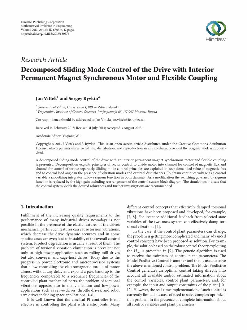
Figure 7 Overall block diagram of decomposed SMC system with IPMSM and flexible coupling
vector 119865 and matrix 119860 are obtained using the model of drivedescribed by (5) (6) As a result two relay control variables119906119889 119906119902defined by (19)ndash(23) guarantee robustness property in
the sliding mode If the integral part of the error functions isavailable the sliding mode starts earlier if compared with theclassical one and the equivalent control could be used for theVSI control
4 Decomposed SMC System Verification
Proposed decomposed SMC strategy was verified in twosteps As the first step control of the plant which consistsof PMSM and flexible load was verified by simulationsSecondly the strategy was applied to the PMSM only forcontrol of its shaft position In spite of some problemwith generation of the observed rotor acceleration which isnecessary as one derivative feedback this control structurewas verified experimentally
Overall block diagram of decomposed sliding modecontrol of the drive with IPMSM and flexible coupling isshown in Figure 7 To avoid control chattering a smoothingintegrator is introduced into magnetic flux and motor torquecontrol channels which are controlled separately The maingoal of linkage magnetic flux control is to comply with vectorcontrol condition keeping stator current component 119894
119889=
0 The goal of torque control channel is to reach and keepdesired position of the load angle in spite of flexible couplingand presence of external disturbances on the rotor and loadside
The feedback derivatives gains as well as ideal positiontrajectory 120579id(119905) computation are based on Dodds settlingtime formulae [24]
120579119871(119904)
120579119871119911(119904)
= [1
1 + (11990411987911990411990415 (119899 + 1))
]
119899
(30)
Mathematical Problems in Engineering 11
120579L
c
Rs
1
s
1
s
1
s
1
s
uq
minus minus
minus
minus
minusminusminus
Ψq
Ψq 1
Lq
id
iq
p120596rΨq
p120596rΨd
lowast lowast
Ψdiq
p120596r
p
120579Lz
g1
g2
g3
g4
g5
Ks
1
JLs
120579r
120579L
Ψqid
ML
120579r minus 120579L
1
Jrs
s
1 + sTf
s
1 + sTf
s
1 + sTf
s
1 + sTf
KSM
MLr
Figure 8 Block diagram of modified decomposed SMC of torque channel
where 119899 is order of the system in sliding mode and 119879119904119904is
prescribed settling time for given control channel The mag-netic flux control channel including smoothing integratoris 2nd order therefore corresponding to above theory onlyone derivative feedback is required Gain 119866
1 of flux channel
derivative feedback with settling time 119879119904Ψ is determined
using (30) for 119899 = 1 as 1198661
= 119879119904Ψ3 The order of the
torque control channel is the sixth therefore five derivativesare needed as feedback Gains 119892
119894(119894 = 1 2 5) of torque
channel derivative feedbacks with settling time119879s120579 are deter-mined using (30) for 119899 = 5 as 119892
1= 51198791199041205799 1198922= 10119879
2
11990412057981
1198923= 10119879
3
119904120579729 119892
4= 5119879
4
1199041205796561 119892
5= 1198795
11990412057959049
As possible modification of the proposed control systemthe signum function is replaced by a transfer characteristicconsisting of a proportional high gain with saturation whichchanges the switching boundary to a boundary layer
Operation in the modified sliding mode implies opera-tion on the linear high gain characteristic enabling rearrange-ment of the block diagrams (valid for both control channels)to avoid the need of the highest output derivative After thisrearrangement the flux control channel operation is based onthe integration of error between demanded and real current119894119889(119905) and one of its feedback with gain 119866
1from real current
119894119889(119905) Block diagram of modified sliding mode control for
torque control channel shows Figure 8The parameters of the IPMSM and load are listed in the
Appendix For whole simulation interval shaft of the motoris loaded with constant friction torque 119872
119871119903= 0 5Nm The
external load torque 119872119871
= 4Nm is applied at 119905 = 05 sand for load angle control simulated as a step change being
zero for the time interval 119905 lt 05 s Computational step ofsimulations was ℎ
119904= 1 120583s for correct simulation of PWM
while the sampling frequency for control algorithm was1ℎ119888= 01ms which corresponds to the sampling frequency
achieved during previous experiments sliding mode controlof the IPMSM rotor position
All the simulations are carried out with zero initial statevariables and a step load position demand 120579
119871119911= 2120587 rad
Prescribed settling time of magnetic flux channel was 119879119904120579
=
20ms and settling time of motor torque channel was chosenas 119879119904120579
= 025 s Error function between prescribed dynamiccomputed using (30) and achieved dynamic is evaluated as119890120579(119905) = 120579id(119905)minus120579119903(119905) (in plots 2-times magnified) Simulation
results for both designed control systems in sliding mode arearranged in the same pattern of subplots in Figures 9 and 10
Subplots (a) show demanded voltages 119906119889119911(119905) and 119906
119902119911(119905) in
the rotor fixed frame (119889 119902) which produce in correspondingwindings currents capable to keep constantmagnetic flux andto developed motor torque achieving prescribed dynamicsand capable to counteract friction torque of motor and exter-nal load torque Subplots (b) show demanded voltages 119906
120572119911(119905)
and 119906120573119911(119905) in the stator fixed frame (120572 120573) These are effective
outputs of the control algorithm and after transformationinto three-phase system and PWM sampled serve to supplyIPMSM terminals
Demanded current 119894119889119911
and 119894119902119911
in the rotor fixed frame(119889 119902) generated by control algorithms are shown in subplots(c) As can be seen 119894
119889119911(119905) is kept close to zero as required
for the vector control of IPMSM Initial positive and neg-ative swings of 119894
119902119911(119905) current produce the acceleration and
12 Mathematical Problems in Engineering
0 02 04 06 08 1
0
5
10
15
20
25
30
minus5
udu
q(V
) uq(t)
ud(t)
t (s)
(a) Demanded voltages (119889 119902)
0
5
10
15
20
25
30
minus20
minus15
minus10
minus5
u120573(t)
u120572(t)
u120572u
120573(V
)
0 02 04 06 08 1t (s)
(b) Demanded voltages (120572 120573)
0
2
4
6
8
10
12
0 02 04 06 08 1t (s)
minus6
minus4
minus2
i diq(A
)
iq(t)
id(t)
(c) Demanded currents (119889 119902)
0
10
20
30
40
50
60
minus20
minus10
0 02 04 06 08 1t (s)
120596r(t)
120596L(t)
120596r120596
L(radsminus
1)
(d) Load and rotor velocity
0 02 04 06 08 1t (s)
120579L(t)
120579r(t)
120579 r120579
L(rad)
0
1
2
3
4
5
6
7
8
minus1
(e) Load and rotor position
0 02 04 06 08 1
0
1
2
3
4
5
6
7
8
minus1
t (s)
120579L(t)
120579id(t)
e120579 = 2(120579id minus 120579L)
120579 id120579 L
(rad)
(f) Ideal load and error position
Figure 9 Decomposed SMC system of the drive with PMSM and flexible coupling
Mathematical Problems in Engineering 13
35
40
0 02 04 06 08 1
0
5
10
15
20
25
30
minus5
udu
q(V
)
uq(t)
ud(t)
t (s)
(a) Demanded voltages (119889 119902)
0
50
100
minus50
u120573(t)
u120572(t)
u120572u
120573(V
)
0 02 04 06 08 1t (s)
(b) Demanded voltages (120572 120573)
0
5
10
15
20
0 02 04 06 08 1t (s)
minus25
minus20
minus15
minus10
minus5
i diq(A
)
iq(t)
id(t)
(c) Demanded currents (119889 119902)
0
10
20
30
40
50
60
minus100 02 04 06 08 1
t (s)
120596r(t)
120596L(t)
120596r120596
L(radsminus
1)
(d) Load and rotor velocity
120579r(t)
120579r(t)
0 02 04 06 08 1t (s)
120579 r120579
L(rad)
0
1
2
3
4
5
6
7
8
minus1
(e) Load and rotor position
0 02 04 06 08 1
0
1
2
3
4
5
6
7
8
minus1
t (s)
120579L(t)
120579id(t)
e120579 = 5(120579id minus 120579L)
120579 id120579 L
(rad)
(f) Ideal load and error position
Figure 10 Modified control system of the drive with PMSM and flexible coupling
14 Mathematical Problems in Engineering
MLr
idz
G1
s
c
Rs
Rs
+um
u
S120579
minusum
+um
u
S120579
minusum
1
s
1
s
1
s
1
s
1
s
ud
uq
minus minus
minus minus
minusminus
minus
minusminusminus
ΨPM
Ψd
Ψq
1
Ld
1
Lq
id
iq
p120596rΨq
p120596rΨq
lowast lowast
lowast lowast
Ψdiq
p120596r
p
g1
g2
g3
120579r
120579r
Ψqid 1
Jrs
s
1 + sTf
s
1 + sTf
s
1 + sTf
120579rz
Figure 11 Overall block diagram of decomposed SMC of IPMSM rotor position
0 5000002
4
6
8
10
12
minus15000minus10000
minus5000minus200
minus150minus100
minus50
dedt
d2 edt
2
e
(a)
0 5000002
4
6
8
10
12
minus15000minus10000
minus5000minus200
minus150minus100
minus50
dedt
d2 edt
2
e
(b)
Figure 12 Designed and measured switching surface for decomposed SMC of PMSM rotor angle
Mathematical Problems in Engineering 15
0 0201 03 04
0
500
1000
minus1000
minus500
t (s)
u998400 du
998400 q(V
)
u998400q(t)
u998400d(t)
(a) Applied stator d q voltages
0
5
minus5
0 0201 03 04t (s)
id(t)
iq(t)
i diq(A
)
(b) Stator d q current components
0
5
minus5
0 0201 03 04t (s)
i120572(t)
i120573(t)
i 120572i120573(A
)
(c) Stator 120572 120573 current components
0
05
minus1
minus05
1 times 105
0 0201 03 04t (s)
120576 r(radsminus
2)
120576r(t)
(d) Rotor angular acceleration
0
50
100
150
200
250
minus500 0201 03 04
t (s)
120596r(radsminus
1)
120596r(t)
(e) Rotor angular velocity
0
5
10
0 0201 03 04t (s)
120579r(t)120579id(t)
120579 r120579
id(rad)
2(120579id minus 120579r)
(f) Rotor and ideal position response
Figure 13 Preliminary experimental results for decomposed SMC of PMSM rotor angle
16 Mathematical Problems in Engineering
deceleration torques which can be followed together with theincrease of 119894
119902119911(119905) after 119905 = 05 s counteracting the external load
torque transmitted via the springThe experimental results for decomposed SMC of rotor
angle are shown in Figure 13 As expected at both controlalgorithms the acceleration period is followed by the deceler-ation one to achieve prescribed response Subplots (e) showthe positions of the rotor and the load The compensationof the external load torque applied at 119905 = 05 s is clearlyevident from the angular displacement between the IPMSMrotor and the load after this torque is applied This entailsa constant torsional deflection of the spring which is clearfrom the constant difference between 120579
119877and 120579L occurring
just after the load torque achieves its steady state The initialdifferences between the rotor and load displacements are dueto the acceleration and deceleration torques being applied viathe torsion spring
Finally subplots (f) of both figures show the idealresponse and response of the control system to the stepload position demand 120579
119871119911= 2120587 rad including magnified
difference between them (2x and 5x) The realisation of theprescribed position dynamics is nearly accurate which isclear from the magnified differences Also the prescribedsettling time for position control is kept well because the loadposition 120579L(119905) passes through 19120587 radian (95 of demandedvalue) at a time close to 025 s
Presented simulation results confirm possibility of de-composed sliding mode control of the load angle in spite offlexible coupling between motor and load As can be seenfrom Figures 9 and 10 subplots (f) the load angle responsesfollow the prescribed ideal response fairly closely Compar-ison of both simulations shows a good agreement with thetheoretical predictions made during both decomposed SMCalgorithms development
To avoid problem with high order derivatives the decom-posed SMC strategy was applied to PMSM for rotor positioncontrol [25] Overall control system block diagram is shownin Figure 11 Design of flux control channel is the same as itwas described for decomposed SMC of PMSM with flexiblecouplingThe torque control channel is in this case the fourthorder therefore three derivatives of controlled variable areneeded as feedback Gains 119892
119894(119894 = 1 2 3) of torque channel
derivative feedbacks with settling time 119879s120579 are determinedusing (30) as 119892
1= 1198791199041205792 1198922
= 1198792
11990412057912 119892
3= 1198793
119904120579216
Designed and measured switching surfaces for PMSM rotorposition control are shown in Figure 12
The experimental results for decomposed SMC of rotorangle (for the idle running PMSM) are shown in Figure 13Nearly constant load torque was developed by locked torqueof the induction machine and applied at 119905 = 027 s Theindividual subplots (a)ndash(c) show the applied stator voltagecomponents and corresponding stator current componentsrespectively Subplot (d) and subplot (e) show the rotorangular acceleration and rotor speed and as the outputs of theobserver taken as the inputs of SMC law Subplot (f) showsresponse of the control system together with the designedideal response to a step position demand of 120579
119903dem = 10 radincluding the 2 times magnified difference between them
Comparison of PMSMwith flexible coupling simulationsand preliminary experiments with decomposed SMC ofPMSM rotor position show a good agreement with thetheoretical predictionsmade during the control systemdevel-opment If suitable observer of control variables is developedit is highly desirable to investigate proposed decomposedSMC strategy experimentally
5 Conclusions
The simulations and preliminary experiment presented pre-dict that the proposed decomposed sliding mode controlsystem and its modification can be made to follow theideal closed loop dynamics of the load angle with moderateaccuracy in spite of flexible coupling between motor andload As a result this is acceptable considering that no motoror driven load parameters were needed for control systemdesign
Some variables of modified control system show sig-nificant overshoots during transients which were limitedin subplots due to graphic purposes In spite of very closetracking of ideal positionmodified control system shows alsosmall overshoots of load position which is not acceptable forposition control systems requiring high precision
The results obtained are sufficiently promising to warrantfurther experimental trials which were not carried out dueto problems with output derivatives of higher order For thefuture work derivatives estimation methods such as observerwith filtering properties or high gain multiple integratorobserver together with measurement of load position withhigher accuracy are recommended
Appendix
Parameters of PMSM are winding resistance 119877119904= 13Ω
winding inductances 119871119889= 144mH 119871
119902= 163mH perma-
nentmagnet fluxΨPM = 013Wb number of pole pair119901 = 5and moment of inertia 119869
119903= 000063 kgsdotm2
Load parameters are load moment of inertia 119869119871
=
0000918 kgm2 and shaft spring constant119870119904= 9Nradminus1
Acknowledgment
The authors wish to thank Slovak Grant Agency VEGA forfunding Project no 1035511 ldquoOptimal Control Techniquesfor Decreasing Losses of AC Drivesrdquo
References
[1] Y Hori H Sawada and Y Chun ldquoSlow resonance ratio controlfor vibration suppression and disturbance rejection in torsionalsystemrdquo IEEE Transactions on Industrial Electronics vol 46 no1 pp 162ndash168 1999
[2] S Katsura and K Ohnishi ldquoForce servoing by flexible manip-ulator based on resonance ratio controlrdquo in Proceedings of theIEEE International Symposium on Industrial Electronics (ISIErsquo05) pp 1343ndash1348 Dubrovnik Croatia June 2005
Mathematical Problems in Engineering 17
[3] S Ryvkin D Izosimov and S Baida ldquoFlex mechanics digitalcontrol designrdquo in Proceedings of the IEEE International Con-ference on Industrial Technology (ICIT rsquo03) vol 1 pp 298ndash303Maribor Slovenia December 2003
[4] K Szabat and T Orlowska-Kowalska ldquoVibration suppressionin a two-mass drive system using PI speed controller andadditional feedbacksmdashcomparative studyrdquo IEEE Transactionson Industrial Electronics vol 54 no 2 pp 1193ndash1206 2007
[5] M A Valenzuela J M Bentley A Villablanca and R DLorenz ldquoDynamic compensation of torsional oscillation inpaper machine sectionsrdquo IEEE Transactions on Industry Appli-cations vol 41 no 6 pp 1458ndash1466 2005
[6] M Vasak M Baotic I Petrovic and N Peric ldquoHybrid theory-based time-optimal control of an electronic throttlerdquo IEEETransactions on Industrial Electronic vol 43 no 3 pp 1483ndash1494 2007
[7] T M OrsquoSullivan C M Bingham and N Schofield ldquoEnhancedservo-control performance of dual-mass systemsrdquo IEEE Trans-actions on Industrial Electronics vol 54 no 3 pp 1387ndash13992007
[8] G Zhang and J Furusho ldquoSpeed control of two-inertia systemby PIPID controlrdquo IEEE Transactions on Industrial Electronicsvol 47 no 3 pp 603ndash609 2000
[9] A N Moser ldquoDesigning controllers for flexible structures withH-infinity120583-synthesisrdquo IEEE Transactions on Control Systemsvol 13 no 2 pp 79ndash89 1993
[10] M Cychowski K Szabat and T Orlowska-Kowalska ldquoCon-strained model predictive control of the drive system withmechanical elasticityrdquo IEEE Transactions on Industrial Electron-ics vol 56 no 6 pp 1963ndash1973 2009
[11] J M Maciejowski Predictive Control with Constraints PrenticeHall London UK 2002
[12] J Wang Y Zhang L Xu Y Jing and S Zhang ldquoTorsionalvibration suppression of rolling mill with constrained modelpredictive controlrdquo in Proceedings of the 6th World Congresson Intelligent Control and Automation (WCICA rsquo06) pp 6401ndash6405 Dalian China June 2006
[13] T Orlowska-Kowalska and K Szabat ldquoDamping of torsionalvibrations in two-mass system using adaptive sliding neuro-fuzzy approachrdquo IEEE Transactions on Industrial Informaticsvol 4 no 1 pp 47ndash57 2008
[14] S J Dodds and J Vittek ldquoSliding mode control of PMSMdrives subject to torsion oscillations in the mechanical loadrdquoin Proceedings of the 13th International Power Electronics andMotion Control Conference (EPE-PEMC rsquo08) pp 2551ndash2558Poznan Poland September 2008
[15] V Utkin J Guldner and J Shi Sliding Mode Control in Electro-Mechanical Systems CRC Press 2nd edition 2009
[16] S Ryvkin and E P Lever Sliding Mode Control for SynchronousElectric Drives CRC press 2011
[17] N Mohan T M Undeland andW P Robbins Power Electron-ics Converters Applications and Design John Wiley amp SonsNew York NY USA 3rd edition 2003
[18] V A Kotelnikov ldquoOn the carrying capacity of the ether andwire in telecommunicationsrdquo in Proceedings of the 1st All-UnionConference on Questions of Communication Moscow RussiaJanuary 1933 (Russian)
[19] R J Marks II Introduction to Shannon Sampling and Interpola-tion Theory Springer Texts in Electrical Engineering SpringerNew York NY USA 1991
[20] S E Ryvkin and D B Izosimov ldquoComparison of pulse-widthmodulation algorithms for three-phase voltage invertersrdquoElectrical Technology no 2 pp 133ndash144 1997
[21] G S Zinoviev Power Electronics Backgrounds PublishingHouse of Novosibirsk State Technical University NovosibirskRussia 2005 (Russian)
[22] W Leonhard Control of Electrical Drives Springer BerlinGermany 2001
[23] P Brandstetter and T Krecek ldquoSpeed and current controlof permanent magnet synchronous motor drive using IMCcontrollersrdquo Advances in Electrical and Computer Engineeringno 4 pp 3ndash10 2012
[24] S J Dodds ldquoSettling time formulae for the design of controlsystems with linear closed loop dynamicsrdquo in Proceedings ofthe 3rd Annual Conference on Advances in Computing andTechnology (ACampT rsquo08) pp 31ndash39 The School of Computingand Technology University of East London London UK 2008
[25] J Vittek S J Dodds P Bris M Stulrajter and P MakysldquoExperimental verification of chattering free sliding modecontrol of the drive position employing PMSMrdquo Journal ofElectrical Engineering vol 59 no 3 pp 139ndash145 2008
Submit your manuscripts athttpwwwhindawicom
Hindawi Publishing Corporationhttpwwwhindawicom Volume 2014
MathematicsJournal of
Hindawi Publishing Corporationhttpwwwhindawicom Volume 2014
Mathematical Problems in Engineering
Hindawi Publishing Corporationhttpwwwhindawicom
Differential EquationsInternational Journal of
Volume 2014
Applied MathematicsJournal of
Hindawi Publishing Corporationhttpwwwhindawicom Volume 2014
Probability and StatisticsHindawi Publishing Corporationhttpwwwhindawicom Volume 2014
Journal of
Hindawi Publishing Corporationhttpwwwhindawicom Volume 2014
Mathematical PhysicsAdvances in
Complex AnalysisJournal of
Hindawi Publishing Corporationhttpwwwhindawicom Volume 2014
OptimizationJournal of
Hindawi Publishing Corporationhttpwwwhindawicom Volume 2014
CombinatoricsHindawi Publishing Corporationhttpwwwhindawicom Volume 2014
International Journal of
Hindawi Publishing Corporationhttpwwwhindawicom Volume 2014
Operations ResearchAdvances in
Journal of
Hindawi Publishing Corporationhttpwwwhindawicom Volume 2014
Function Spaces
Abstract and Applied AnalysisHindawi Publishing Corporationhttpwwwhindawicom Volume 2014
International Journal of Mathematics and Mathematical Sciences
Hindawi Publishing Corporationhttpwwwhindawicom Volume 2014
The Scientific World JournalHindawi Publishing Corporation httpwwwhindawicom Volume 2014
Hindawi Publishing Corporationhttpwwwhindawicom Volume 2014
Algebra
Discrete Dynamics in Nature and Society
Hindawi Publishing Corporationhttpwwwhindawicom Volume 2014
Hindawi Publishing Corporationhttpwwwhindawicom Volume 2014
Decision SciencesAdvances in
Discrete MathematicsJournal of
Hindawi Publishing Corporationhttpwwwhindawicom
Volume 2014 Hindawi Publishing Corporationhttpwwwhindawicom Volume 2014
Stochastic AnalysisInternational Journal of

2 Mathematical Problems in Engineering
Different approaches depend on application of a sliding-mode control robustness of which is capable to eliminateinfluence of control plant parameters changes and also toeliminate external disturbances if these are presented in thecontrol system dynamics [13ndash16]
The main goal of this paper is to present the novel slidingmode control based control system for plant with elasticsconnections that combines robustness with chattering freecontrol while exploiting voltage source inverter (VSI)
11 Control Plant Model The control plant has three impor-tant parts
(i) VSI that feeds IPMSM(ii) Interior Permanent Magnet Synchronous Motor(iii) Elastic mechanical transmission for example a gear-
box with external load
Mathematical models of these plant parts are necessaryfor control system design therefore their description ispresented in the following
12 Voltage Source Inverter As it is known feed voltagescorresponding to the demanded operation mode of thesynchronous motor should be generated on its windingsA supplyline with three-phase voltages (119860 119861 119862) with fixedamplitude and frequency usually acts as the source of powerenergy Power converters are used to transform these voltagesinto three-phase supply voltages for a synchronous motor(119877 119878 119879) having a variable magnitude and frequency Three-phase power converters are built using power transistorsworking in relay mode [17]
The phase output voltage of the power converter rep-resents in this case a sequence of voltage impulses Thishigh frequency sequence is averaged in the synchronousmotor winding owing to its filtering propertyThe theoreticalbackground is based on Shannon-Kotelnikov or the samplingtheorem [18 19] This average voltage could be consideredas a continuous phase voltage on the synchronous motorwinding needed to solve the control problem Thus thephase output voltage of the power converter from the controlviewpoint has a dual character
(a) pulsemdashby nature(b) continuous averagemdashfor electric motor control
To realize the specified transformation of the three-phasevoltages widely the scheme of power transformation witha direct current link (Figure 1) is used In this case thethree-phase supply line voltages are rectified by means of athree-phase rectifier and smooth out by an output capacitorObtained constant voltage supplies an input of the three-phase VSI From DC link voltage inverter produces desiredthree-phase voltages of variable frequency and magnitude
The voltage source inverter [16] transforms a DC inputvoltage in three-phase variable voltages of a constant orvariable frequency andor amplitude To obtain the neededphase voltage the voltage transformation pulse method isused It is based on the application of a switch operationmode
T
S
R
C
B
A
Rectifier VSI
Uin
=
= sim
sim
Figure 1 Power converter with a direct current link
pR pS pT
KRUinKS KT
UR US UT
USO
URO
UTO
Figure 2 The simplified schema of the three-phase VSI bridge
of power semiconductor devices (switches)They connect anyoutput phase of the load to a source of constant voltage 119880in
One of themostly used VSI is the three-phase bridge withthe isolated neutral shown in Figure 2 It has a star connectedload with a parallel connection of three phases on-off powerswitches 119870
119895(119895 = 119877 119878 119879) A control signal 119901
119895(119901119895isin 0 1) of
each switch controls the connection of the VSI output phaseload either to a positive potential or to the negative one of theconstant input voltage 119880in
Thus depending on a control signal of each switch theoutput phase voltage 119880
1198950is equal at any moment to input
constant voltage119880in or zeroThe vector of VSI output voltageU119879 = (119880
120572 119880120573) in a fixed orthogonal coordinate system
(120572 120573) is defined by Clark transformation as
10038161003816100381610038161003816100381610038161003816
119880120572
119880120573
10038161003816100381610038161003816100381610038161003816
=2
3
1003816100381610038161003816100381610038161003816100381610038161003816100381610038161003816100381610038161003816
1 minus1
2minus1
2
0radic3
2minusradic3
2
1003816100381610038161003816100381610038161003816100381610038161003816100381610038161003816100381610038161003816
100381610038161003816100381610038161003816100381610038161003816100381610038161003816
119880119877119874
119880119878119874
119880119879119874
100381610038161003816100381610038161003816100381610038161003816100381610038161003816
(1)
where numerical factors of a transformation matrix aredirecting the phase load terminals (119877 119878 119879) As phase voltageshave relay character the voltage output vector U can accept
Mathematical Problems in Engineering 3
R
120572
120573
120593
S
T
Uref
U6(101)U5(001)
U4(011)
U3(010) U2(110)
U1(100)
2Uin3
12minus12
minusradic3
2
radic3
2
Figure 3 Vectors of VSI in complex plane
only eighth values two of them are zero 1198800and other six
119880119894(119894 = 1 6) are nonzero and create the tops of the regular
hexagon (Figure 3) Its symmetry axes are directed on thephase load terminals
The module of the above-mentioned six nonzero vectorsdepends on the load connection and on the value of the inputdc line voltage 119880in In the load connected as ldquostarrdquo circuitit is equal to 2119880in3 The combination of phase switches(119901119877 119901119878 119901119879) controls the possible vector of the output voltage
119880119894presented in Figure 3 The zero vectors correspond to two
combinations of the switch positions either all are connectedto positive potential (111) or to negative potential (000)
The VSI switch control providing the needed outputvoltage has two independent parts [20 21]
(i) the modulation law that defines the part of themodulation period in which the power switch isconnected either to the positive potential (119880in) or thenegative one (0)
(ii) the switching law that defines a sequence of switchingof phase switches on the modulation period
In this case each phase output voltage represents asequence of various duration squared impulses magnitude ofwhich is equal to 119880in that is the feed voltage A sequence ofthese impulses being averaged owing to filtering propertiesof the load forms a phase output voltage on the load creatinga control tool In analysis of the VSI operation and controlsystem synthesis it is therefore necessary to consider thedual character of an output voltage vector On one hand itis characterized at any moment by the instantaneous valuecaused by instantaneous positions of the power switches Onthe other hand owing to that the averaging properties of theload it possesses an average on the modulation period valuedefining the VSI feature is a part of an automatic controlsystem These problems will be also considered furtherduring the design of control system for the drive employingsynchronous motor
13 Interior Permanent Magnet SynchronousMotor The clas-sical mathematical model that considers the basic physical
features of the processes inside of the motor shown inFigure 4 received by standard assumptions is used for motordescription [13ndash15] In the frame of these assumptions themathematical description of IPMSM includes the followingthree groups of equations
(i) equations of electric balance in its windings(ii) equation of the electromagnetic torque developed by
the electric motor(iii) equation of mechanical movement (Newtonrsquos second
law for a rotary motion)
The third equation based on formula of mechanicalmovement is general for all electric motors and has thefollowing form
119869119889Ω
119889119905= 119872el minus119872 (2)
where 119869 is the moment of inertia of all rotational partsreduced to the shaft of rotor Ω is the rotor angular speed119905 is the current time and 119872el is the electromagnetic torquedeveloped by the motor 119872 = sum119872
119897(119865119894) is the sum of the
torques of the external forces enclosed to a rotorThe equations of electric balance based on Kirchhoff rsquos
second law and the equations of electromagnetic torque aredefined by the electric and magnetic circuits of the IPMSMand the physical processes inside of it In the case of IPMSMthe magnetic flux is created by permanent magnets locatedinside of the rotor Such placement of permanent magnetsgives to the rotor feature of the salient poles and the IPMSMhas a nonuniform air gapDue to nonuniformity of the air gapthe magnetic flux creates an additional (reluctance) torque
It is well known that mathematical description of theelectromechanical transformation of power in the IPMSMusing the actual phase currents and voltages as independentvariables is capable to describe the physical processes insideof the motor On the other hand such description is relativelycomplicated for analysis of the dynamical processes andresults in a system of nonlinear differential equations withperiodically changing coefficients due to change of rotorposition
The successful choice of transformation into axes (0 119889 119902)plays a fundamental role in the theory of synchronousmachines and the theory of automatic drives and clearlyproves the following statements First thanks to the rotatingcoordinates system connected to a rotor the differentialequations describing the synchronous motor dynamics haveconstant coefficients
Second orientation of a datum line 0 on the axis of rota-tion makes the differential equation independent regardingto a zero sequence current It must be emphasized that thezero sequence current does not participate in the creationof air gap magnetic field and it has no influence on theelectromechanical processes in the motor It creates only anadditional loading of windings and semiconductor devicesThe traditional connection of motor phase windings ldquostarrdquo orldquodeltardquo automatically provides cancellation of a zero sequencecurrent that is it eliminates additional thermal losses It leads
4 Mathematical Problems in Engineering
uB
S
A
q
d N
uC
uA
B
C
Figure 4 IPMSM
to simplification of mathematical description of synchronousmotor Elimination of differential equation for the zerosequence current reduces the system order In this case theconsidered three-phase synchronous motor is replaced by atwo-phase ldquoidealizedrdquo one (the generalized electric machine)which from the point of view of the electromagnetic processesrepresents the collector machine
The transformation from the three-phase coordinates sys-tem to the rotating two-phase system (0 119889 119902) is implementedvia a Park transformation matrix
119862 = radic2
3(cos 120574119860
cos 120574119861
cos 120574119862
minus sin 120574119860
minus sin 120574119861minus sin 120574
119862
) (3)
where 120574119895is an electric angle between a rotor axis119889 and a stator
phase axis 119895 (119895 = 119860 119861 119862) and radic23 is a factor for powerinvariance
The electric variables in a rotating system 119894119889 119894119902 119906119889 119906119902are
also connected to phase variables
119868 = 1198621198681015840
119880 = 1198621198801015840
(4)
where 119868119879 = (119894119889 119894119902) 1198681015840119879 = (119894
119860 119894119861 119894119862) 119880119879 = (119906
119889 119906119902) 1198801015840119879 =
(119906119860 119906119861 119906119862)
The equations of electric balance and the electromagneticmoment for IPMSM in the rotating frame are as follows
119889119894119889
119889119905=
1
119871119889
(minus119903119894119889+ 119871119902120596119894119902) +
1
119871119889
119906119889
119889119894119902
119889119905=
1
119871119902
(minus119903119894119902minus 119871119889120596119894119889minus Ψ119891120596) +
1
119871119902
119906119902
119872el =3
2119901 [Ψ119891+ (119871119889minus 119871119902) 119894119889] 119894119902
(5)
Mel
Ks
JL
120579L
120579r
MLr
Jr
ML
Figure 5 Elastics mechanical transmission
where 119894119889 119894119902are the currents in the stator windings 119906
119889 119906119902are
the voltages in the stator windings 119903 is the active resistanceof a stator windings 119871
119889 119871119902are the direct and quadrature axis
inductances of stator windings 119901 is the number of pair poles120596 is the electric angular speed Ψ
119891is an excitation flux
14 Elastic Mechanical Transmission The behavior of thedriversquosmechanical part (Figure 5) causing torsional vibrationscould be described as follows The IPMSM with moment ofinertia 119869
119903produces the electromagnetic torque on its shaft
119872el The angular speed of the motor shaft is equal to Ω Thereduction factor of mechanical train from a motor shaft tothe final control element (load) is equal to 1 Load inertia (themoment of inertia 119869
119871) is coupled to the motor via the elastic
mechanical connection with a string factor 119870119878 Two external
disturbance torques119872119871119903and119872
119871operate respectively on the
rotor and on the load sides The inertial load rotates with theangular speed Ω
119871 The angular position of the final control
element is 120579119871
Based on torque balance the behavior of the elasticsmechanical transmission is described by following differenceequations
119889120579119903
119889119905= Ω119903
119889Ω119903
119889119905=
1
119869119903
[1198721119897minus119872119871119903+ 119870119878(120579119871minus 120579119903)]
119889120579119871
119889119905= Ω119871
119889Ω119871
119889119905=
1
119869119871
[119870119878(120579119903minus 120579119871) minus 119872
119871]
(6)
15 Sliding Mode Control Backgrounds Sliding mode is aspecial type of behavior of a relay system [15 16]
119889119909 (119905)
119889119905= 119897 (119909 119905) + 119861 (119909 119905) 119906 (119905) (7)
119906119894(119909 119905) =
119906+
119894(119909 119905) if 119878
119894(119909 119905) gt 0
119906minus
119894(119909 119905) if 119878
119894(119909 119905) lt 0
(8)
Mathematical Problems in Engineering 5
where 119909(119905) is a state vector 119909(119905) isin 119877119899 119897(119909 119905) is a system vector119897(119909 119905) isin 119877
119899 119906(119905) is a control vector 119906(119905) isin 119877119898 119899 ge 119898 119906
119894(119905)
is a component of the control vector 119906(119905) 119894 = 1119898 119861(119909 119905) is amatrix 119861(119909 119905) isin 119877119899times119898 119878
119894(119905) is a switching function
The main feature of this mode is that none of the usedgeneral switched structures can realize such behavior Thesliding mode occurs in the intersection of all m surfaces
119891119894= 0 (9)
by high frequency switching of the control components119906119894(119909 119905) (8)
The vector function 119865
119879
= (1198911 119891
119898) is a
function of the system variables 119909(119905)Usually it is an error
function thatmust be led to zero by using the vector switchingfunction 119878119879 = (119878
1 119878
119898)
Formally the aim of control is to force state system 119909(119905)to reach the manifold
119865 = 0 (10)
and ldquoslidesrdquo on this manifold to the reference point indepen-dently of the system dynamics
In this case the control design procedure is decoupled intothe two tasks
(i) sliding mode design in the space of the vector func-tion 119865 isin 119877
119898(ii) motion design on the intersection of all m surfaces in
the state space with order (119899 minus 119898)
Solution of the first task is based as it is considered inslidingmode analysis on the Lyapunov stability of the controlplant in the space of the vector function 119865 isin 119877
119898 A typicalsliding mode control variable 119906 has the form
119906 = minus119880 (119909) sgn (119865) (11)
where 119880(119909) is the square diagonal matrix of control magni-tude and sgn(119865) is the vector of the signs of error functions[sgn(119865)]119879 = (sgn119891
1 sgn119891
119898) It guarantees that the
system state will reach the sliding manifold in finite timefrom the initial condition which has been bounded by thevalue of the matrix 119880(119909) constituent and will keep to it Thismagnitude bounds the uncertainty of the system the loadvalue unto which the system is commonly robust Specialtask is the design of a transition law between the designedcontrol (11) and the switching control (8) which depends onthe features of the relay system (7)
Motion on the sliding manifold is described by theequivalent control 119906eq(119909) Its calculation is based on thecondition that the time-derivative of the function 119865 on thesystem trajectories is equal to zero
119889119865
119889119905= 119866119897 + 119866119861119906eq = 0 (12)
where 119866(119909) = 120597119865120597119909 119866(119909) isin 119877119898times119899 is a gradient matrix
det119866119861 = 0In this case the equivalent control 119906eq(119909) that is a contin-
uous control which guarantees the same motion if all needed
information about the load and the system uncertainty wereavailable is calculated
119906eq = (119866119861)minus1
119866119897 (13)
and the system motion in the sliding mode is described as
119889119909
119889119905= 119897 minus 119861(119866119861)
minus1
119866119897 (14)
Using (10) the system order can be reduced to (119899 minus 119898) andthe system description is
1198891199091
119889119905= 1198971[(1199091 119905)] (15)
where 119909119879 = (1199091 1199092) 1199091isin 119877119899minus119898 119909
2isin 119877119898 1198971[(1199091 119905)] 1198971isin
119877119899minus119898
2 Sliding Mode Control Design
21 Control Goal An electrical motor in the drive structurecarries out a transformation of the electric energy into amechanical one that moves the mechanisms participatingin the working process Technology requirements for thisprocess define the necessity and expediency of maintenanceat the reference level of those or other mechanical variablesfor example position speed acceleration torque and soforth of the mechanism tip
In our case the main adjustable variable is a load position120579119871connected to the rotor shaft by elastics connection This
position should be equal to the reference values 120579119871119911(119905) In
the most general case the reference value 120579119871119911(119905) is a function
of time This is essential for the servo control problem Theactual load angular position should reproduce all changes ofthe reference value with prescribed accuracy Special cases ofthis problem are
(i) stabilization of the load position at the referenceconstant level
(ii) the load angular position change under the referencelaw
(iii) restriction of the load angular position by an admis-sible value
The number of the control variables depends on thenumber of the control plant independent controls In thecase of IPMSM there are two independent controls (see (4))and there is a possibility together with the requirementson the mechanical coordinate to fulfill the requirement onprofitability of drive work Its indicators are the efficiencycoefficient characterizing power losses and cos120593 character-izing consumption of the reactive power
The main control goal is to maintain the reference valueof the load angular position 120579
119871in combination with power
requirements In relation to the reference demands anychange of the load torque has to be carried out exactly andfast Due to discontinuous work of power converter solutionof control problem requires formation of such switch controlto complywith the above-mentioned requirements Referring
6 Mathematical Problems in Engineering
to the theory of systems with discontinuous controls inthis case it is quite natural Essential nonlinearities of thedrives supplied by power converter can bring up a variety ofapproaches to the solution of a control design problem
Several basic approaches to the synthesis of IPMSMdrives control can be defined
(i) single-loop control(ii) single-loop decomposition value reference(iii) cascade (subordinated) control
In the first case the drive is considered a unitThe controlsynthesis interfaces to the solution of the nonlinear problemThe switching frequency and duration of power switcheson states are generated automatically in the closed loop asan auxiliary element in the solution of the primary drivecontrol goal Such systems possess high dynamics and smallsensitivity to drive parameter changes and to external distur-bances Unfortunately the automatically generated switchingfrequency of the power switches is not constant because itdepends on the initial conditions This leads to the powerswitches losses increase and to the drive mechanical noise
In the second case two independent problems are con-sidered a problem of IPMSM control design and a problemof power converter control design After transformation ofIPMSM into system rotating at rotor speed the control lawsynthesis is based on the assumption that the power convertergenerates DC input currents and voltages responding tothe solution of the primary control goal Inverse Clark andPark transformations change the constant input currents andvoltages into voltages and currents with variable frequencyand magnitude The problem of the power converter controlis to select suitable switching of eight available switchingvectors to follow required voltages with variable magnitudeand frequency as close as possible providing the completesolution of the control problem
Power converter control deals with the use of the modu-lation techniques based on a high frequency to generate theinput voltages of the motor DC output currents and voltagesof control algorithm represent for the power converter asequence of impulses of various durations This sequence ofimpulses being averaged due to the filtering effect of the loadthat is the IPMSM forms a continuous load voltage which issubject to control In this case the indicators characterizingthe discontinuous control that is its modulation such asswitching frequency and pulse ratio are formed outside ofpower converter that is feed forward (program) controlis executed However with such type of control the auto-matic compensation of external disturbances and internalparameter changes is possible only in the upper loop of themechanical coordinate control
The control problem in the third case exploits the prin-ciples of the cascade (subordinated) control Decompositionof an initial problem of the drive control on drive processesrates is required The control problem for each of processesis handled separately Natural splitting of the drive processesrespects the electromagnetic modes which are fast and themechanical modes which are usually slow In relation to thefast processes the mechanical variables are quasiconstants
Hence the electromagnetic processes control problem isreduced to a control of the electromagnetic torqueThe torquereference is formed in a slow control loop of the mechanicalmovement which is based on the movement equation (2)Since the value of the electromagnetic torque is defined bythe DC values (as the current in the DC motor winding)the control problem for a fast internal loop is reduced to afeedback current control using the power converter Changeof discontinuous controls that is the switching frequencyand duration of the switching of power switches are generatedautomatically in the closed loop as an auxiliary elementof the control problem solution The current control looppossesses high dynamics and small sensitivity to motorparameter changes and external disturbances However it isnecessary to notice that as in the first case the switchingfrequency of power switches is generated automatically andits value depends on initial conditions Therefore it similarlyincreases switching losses of the power converter switchesand increases mechanical drive noise
3 Single-Loop Control
31 Sliding Mode Functions Selection As it was explainedabove the basic controlled variable in an electrical drive is theload angular position 120579
119871 which ideally should be equal to the
reference 120579119871119911(119905) There are two different operating conditions
for the IPMSM Better electrical drive performance can beachieved by obtaining the largest possible efficiency whilekeeping the power factor equal to one For simplification ofthe control design the above-mentioned power requirementscould be transformed into a reference of stator currentcomponent 119894
119889119911computed for the IPMSM known parameters
and a measured component of the stator current 119894119902 In
practice to simplify control algorithm and to keep linkageflux of motor constant [22 23] the reference of the statorcurrent component 119894
119889is prescribed as 119894
119889119911= 0 In this case
value cos120593 is near its optimum values [16]Using such references that is the load angular position
120579119871119911(119905) and the stator current 119894
119889119911(119905) it is possible to achieve
specific requirements of the IPMSM control Having chosenthose references the electrical drive behavior is describedby the error functions of the controlled variables which aredeviations of the controlled variables actual values and thereferences
1198851=1198894
(120579119871119911minus 120579)
1198891199054+ 1198623
1198893
(120579119871119911minus 120579)
1198891199053
+ 1198622
1198892
(120579119871119911minus 120579)
1198891199052+ 1198621
119889 (120579119871119911minus 120579)
119889119905
+ 1198620(120579119871119911minus 120579)
1198852= 119894119889119911minus 119894119889
(16)
where 1198620 1198621 1198622 1198623are constants
The order of the error function depends on the modelof control plant Its derivation must be linear function of
Mathematical Problems in Engineering 7
the control variables To solve this control problem forexample to make the error functions equal to zero it meansto synthesize switching control actions of power converteroutput voltages which feeds the IPMSM stator windingsFrom the point of view of output voltages the above errorfunction (16) would be zero simultaneously
In this case current 119894119889is equal to its reference value 119894
119889119911
and the error between the reference 120579119871119911(119905) and the actual
load angular position 120579119871 will tend to zero if the factors of
difference equation have been chosen from a condition of adesired placing of difference equation roots on the left halfof complex plane The convergence rate of actual value to thereference one is defined by the positions of the roots
One of the possible variants tomaintain the simultaneousequality for functions (16) as zero is the organization of asliding mode on crossing of surfaces 119885
1= 0 and 119885
2=
0 The solution for this problem is based on the two-stepdesign procedure [17] The initial problem of control designis divided into tasks of smaller complexity as a two-stepprocess taking into account operating features of the IPMSMand power converter As the first step features of the motorare considered only A problem can be solved by synthesis of asliding motion using a fictitious control vector and a classicalmathematical model of the IPMSM (see Park equations (3))The fictitious control variables are two-phase voltages of thebi-phase Park modelThey do not exist as real however suchmodel is very convenient for the control system design Thereal motor for control is a three-phase voltage system formedby the converter phase switching control The second steptherefore carries out the transition to actual controls takinginto account functioning features and peculiarities of thethree-phase semiconductor power converter of various types
311 The First Step As it was mentioned the possibilityto organize sliding movement and to design the necessarycontrol variables can be solved using the equation for initialdynamic systemmotion projection for example the IPMSMat an error subspace of the controlled variables 119885 If Parkdescription of the IPMSM and the control variables specifiedabove are used the projection equation has the followingform
119889119885
119889119905= 119865 + 119860119880 (17)
where vector 119865 = 119889119911119911119889119905 minus 119866119891 and matrix 119860 = 119866119861 do not
depend on the control vector119880 but are defined by the columnvector 119865119879(119909 119905) = (119891
1 1198912) and the control matrix 119861(119909 119905) of the
motor respectively The existing conditions directly dependon matrix 119860
Motor and load can be modeled by the system ofdifferential equations of seven order (5) (6) where U119879 =
(119906119902 119906119889) is a fictitious control vector components of which
are voltages 119906119889 119906119902on a fictitious bi-phase windings in a
rotating coordinate system (119889 119902) The error function vector119885119879
= (1198851 1198852) contains only two components In this case
vector 119865 and matrix 119860 can be combined into equation formatrix 119860
119860=(
minus119870119878
119869119871119869119903
(
119871119889minus 119871119902
119871119889
) 119894119902minus119870119878
119869119871119869119903
[(
119871119889minus 119871119902
119871119902
) 119894119889+Ψ119891]
minus1
119871119889
0
)
(18)
After inspection of matrix 119860 it is visible that component119906119902of a control vector 119880 has not influence on sliding mode
occurrence at the surface 1198852= 0 Hence using a method of
control hierarchy [15 16] it is possible to carry out decompo-sition of an initial design problem into two independent one-dimensional problems on the existence of one-dimensionalsliding modes on surfaces 119885
1= 0 and 119885
2= 0 The control
design and a choice of the control variables magnitudes foreach of them are carried out under assumption for existenceconditions of one-dimensional slidingmovementThe slidingmotion is designed at first on surface 119885
2= 0 using 119906
119889and
then on surface 1198851= 0 using control 119906
119902
The control algorithm
119906119889= 1199061198890sgn119885
2(19)
and the inequality
1199061198890ge10038161003816100381610038161003816119906119889 eq
10038161003816100381610038161003816=10038161003816100381610038161198912
1003816100381610038161003816 (20)
provide contrast of signs on error function 1198852and its
derivative that is the slidingmode performance for the abovespecified existence conditions for a scalar case
By solving the control design problem for the secondcomponent of a control vector 119906
119902 the principle of control
hierarchy is used It is supposed that sliding mode on surface1198852= 0 takes place and it is necessary to provide slidingmode
on surface 1198851= 0 In this case according to a method of
equivalent control (14) in the first equation of system (18)instead of control 119906
119889 its value namely the equivalent control
119906119889 eq is substituted Sliding mode on surface 119885
1= 0 and
hence on the crossings of surfaces 1198851= 0 and 119885
2= 0 will
take place if
119906119902= 1199061199020sgn119885
1 (21)
1199061199020ge10038161003816100381610038161003816119906119902 eq
10038161003816100381610038161003816=10038161003816100381610038161198911
1003816100381610038161003816 (22)
It is important to notice that on ldquoreasonablerdquo operatingmodes the magnetic fluxΨ = Ψ
119891+ (119871119889minus119871119902)119894119889119911causing elec-
tromagnetic torque119872el has to be different to zero otherwisethere would be no possibility to control the electromagnetictorque of the synchronous motor Hence at Ψ = 0 there isa basic possibility of performance of condition (22) at theexpense of a choice of an enough large value 119906
1199020 that is
maintenance of slidingmode existence along the surface1198851=
0As a first stage result decomposition of an initial design
problem was carried out and two one-dimensional problemsabout the occurrence of sliding modes were consideredindependently The received equations (19) (21) describe
8 Mathematical Problems in Engineering
working control and the inequalities (20) (22) at 119885 = 0
define a class of admissible perturbations and the referencesreproduced without a dynamic tracking error
312 The Second Step It is a transition from the fictitiouslyentered control vector U119879 = (119906
119889 119906119902) to the real control of
power converter feeding the IPMSM The stator windingsare fed by a three-phase VSI It can accept only 8 outputvoltage vectors six of them having nonzero values separatedan angular distance of 1205873 from each other and two of themwith zero value (Figure 3)
Each of these vectors has a fixed direction and none ofthemcoincideswith the formally entered control vectorU119879 =(119906119889 119906119902) either in direction or in value Values of magnitude of
the components formally entered control vector are chosenaccording to inequalities valid for the control variables in therotating coordinate system (119889 119902)
For the output phase voltages of the power converterdesign it is possible to use (4) with a transformation matrix(3) connecting formally entered control variables 119906
119889 119906119902and
real phase voltage In this case the phase voltages obtained bythe slidingmode designed at the first step will represent sinu-soidal ones with frequency equal to multiple angular speed ofthe IPMSM rotor and both of variable magnitude and phaseThese phase voltages including a high-frequency componentcould be obtained on the output of power converter by usinghigh-frequency PWM which requires calculation of the timelength for switches on state and corresponding sequenceof switching However such approach requires additionalcalculations in connection with the allocation of equivalentcontrol variables (necessary for PWM calculation) and willhave negative influence on one of the basic property of slidingmode which is the simplicity of implementation
The alternative approach to the design of power converteroutput phase voltages is based on a sufficient existence ofa sliding mode condition in the systems with redundantcontrol [16] Conditions for choices of magnitude values offormally entered control variables are based on inequalitiesIt allows space allocation of fictitious control variables in thiscase 119906
119889 119906119902 in the area of the admissible control variables
119880lowast guaranteeing sliding mode existence For the design of
real control variables for example three phase voltages it isobvious that their total projections to axes (119889 119902) coincidedon a sign with the designed fictitious controls and values ofprojections satisfied sliding mode inequalities on crossing ofchosen surfaces through the projections value that is thevalues of the formally entered control variables 119906
119889 119906119902 will
change during the motor operationFor the design of such control variables it is necessary
to transform the domain of admissible controls received inthe rotating coordinate system using an inverse linear Parktransformation
[119906120572
119906120573
] = [cos 120574119860
minus sin 120574119860
sin 120574119860
cos 120574119860
] sdot [119906119889
119906119902
] (23)
at a fixed coordinate system of the control space 119906119889 119906119902
u120572
u120573 120596r
Ulowast4Ulowast
1
Ulowast3Ulowast
2
ud eq
ud eq
minusud eq
minusud eq
Figure 6 Slidingmode areas for admissible control119880lowast in stationarycoordinate system (119906
120572 119906120573)
In this fixed coordinate system the relative position ofthis area and the output vectors of the power converter (23)must be analyzed again The transformed area of admissiblecontrols 119880
lowast (Figure 6) has the same configuration as theoriginal area in the rotating coordinate system (119906
119889 119906119902) but it
is not fixed Instead it rotates with the electrical rotor speed120596
VSI output voltage vector can accept six nonzero val-ues separated an angular distance of 1205873 from each other(Figure 3) After direct check there is no doubt that at all thevalues 120574
119895(119895 = 119877 119878 119879) and any values of sgn 119885
1and sgn 119885
2
of each of the subareas of area of admissible values of controlwill belong to at least one of six realized nonzero values of aVSI output voltage vector if
119880in ge 119880lowast
in =3
2radic1199062
1198890+ 1199062
1199020+ radic3119906
11988901199061199020 (24)
sgn 119878119895= sgn (119896 sgn 119878
2cos 120574119895minus sgn 119878
1sin 120574119895) (25)
radic
81198802
in + 91199062
1198890+ 3radic3119906
1198890radic16119880
2
in minus 91199062
1198890
241198802
in minus 91199062
1198890minus 3radic3119906
1198890radic16119880
2
in minus 91199062
1198890
le 119896 le radic
241198802
in minus 91199062
1199020minus 3radic3119906
1199020radic16119880
2
in minus 91199062
1199020
81198802
in + 91199062
1199020+ 3radic3119906
1199020radic16119880
2
in minus 91199062
1199020
(26)
It is obvious that in this case there is a possibility toallocate ranges of angle values 120574
119895 at which the sign of the
VSI phase switch control 119901119895coincides with the sign or the
opposite one of the fictitious control sign 1198851or sign 119885
2and
does not depend on a sign of the second one Angle values of120574119895 at which a sign change of the operating signal occur and
values of control signal 119901119895are defined by the formula (25)
Mathematical Problems in Engineering 9
In connection with the above the control law of switchingvariables formation 119901
119895 which depends on angle values 120574
119877
can be presented in the form of a logic table with two inputvariables an angle rotor position and four signs functions
The obtained conditions of sliding mode existence aresufficient for any instantaneous values 119906
1198890 1199061199020
taken fromthe sets caused by inequalities of a choice of control magni-tudes that is for sliding movement on both surfaces 119885
1=
0 and 1198852
= 0 It is necessary to notice that the offeredsliding mode control is robust and has not high requirementsbesides constancy of input voltage VSI 119880in and definition ofrotor angular position 120574
119877 The sliding mode will remain in
operation even if the value of input voltage VSI 119880in changessubstantially The unique limitation according to inequality(24) is the bottom bound of its change 119880
lowast
in This way it ispossible to simplify the scheme of a direct current link and torefuse the smoothing capacity The angular position shouldbe defined completely within one of 12 sectors According to(24) and (26) from which 119880in gt 119880
lowast
in high demands also arenot made to border definition between sectors on accuracy
32 Single-Loop Decomposition Control As it was writtenabove the main disadvantage of the single-loop sliding modecontrol is that the automatically generated switching fre-quency of the power switches is not controllable It dependson the initial conditions and could vary in a wide range Thisleads to the negative effects as increase of power switcheslosses and to higher driversquos mechanical noise
One of the possible ways to eliminate this disadvantageis exploitation of the single-loop decomposition controlconsidering separately two independent problems a problemof IPMSM control design and a problem of power convertercontrol design The power converter control problem dealswith the exploitation of the modulation based on a high-frequency connection to the input voltages of motor phasewindings independently
As the first step of a single-loop decomposition controlfictitiously entered control voltage vector U119879 = (119906
119889 119906119902) is
replaced with the voltage derivations V119879 = (V119889 V119902)
119889119906119889
119889119905= V119889
119889119906119902
119889119905= V119902 (27)
where V119879 = (V119889 V119902) is a fictitious control vector
In this case the IPMSMwith the elastics joints is modeledby a nine-order system of differential equation (5) (6) (28)The error function vector 119885
119879= (1198851 1198852) contains again two
components However the order of the error functions is 1degree higher
1198851=1198895
(120579119871119911minus 120579)
1198891199055+ 1198624
1198894
(120579119871119911minus 120579)
1198891199054
+ 1198623
1198893
(120579119871119911minus 120579)
1198891199053+ 1198622
1198892
(120579119871119911minus 120579)
1198891199052
+ 1198621
119889 (120579119871119911minus 120579)
119889119905+ 1198620(120579119871119911minus 120579)
1198852=119889 (119894119889119911minus 119894119889)
119889119905+ 1198700(119894119889119911minus 119894119889) (28)
where 1198620 1198621 1198622 1198623 1198624 1198700are constants
In this case the error between the reference value 119894119889119911
and the actual current 119894119889
by 1198700gt 0 tends exponentially
to zero according to a law having a time constant equal to11198700 The error between the reference 120579
119871119911 and the actual
load angular position 120579119871 will tend toward zero if the factors
of difference equation have been chosen from a condition ofa desirable placing of difference equation roots on the left halfof complexplane The convergence rate of actual value to thereference one is defined by the positions of the roots
For the design of the sliding mode on the intersectionof the surfaces 119885
1= 0 and 119885
2= 0 (17) is used However
the vector 119865 and matrix 119860 are received using the completedrive model (5) (6) and (27) As a result two relay controlvariables V
119889 V119902 defined by (19)ndash(23) guarantee robustness
property in the sliding modeFor the second step which is power converter real control
design fictitiously entered control vector V119879 = (V119889 V119902)
received in the first step cannot be used VSI control canchange only the average value of the output voltage Thereference voltage value ofVSImust be received via integrationof the fictitiously entered control vector V119879 = (V
119889 V119902)
components In this case the indicator characterizing the VSIdiscontinuous control that is its modulation is formed forthe power converter from the outside that is feed forward(program) control The pulse ratio is formed as a function ofthe reference voltage value
Due to choice of switching frequency there is a possibilitytominimize driversquos switching losses However it must respectthe fact that to obtain good results the PWM frequency mustbe a few times higher than the band pass highest frequencyof the controlled plant
One disadvantage of this approach if compared withclassical one is the need of the additional derivation ofthe control variables It is well known that the derivationsof high order have larger influence on the control systemdynamics Another approach that allows using the integral ofthe control variable error instead of the 5th order derivationwas investigated In this case all advantages of the abovedecomposed sliding mode control design are saved
The behavior of the IPMSM with the elastics connectionis described by the same seventh-order differential equationsystem of (5) (6) with the fictitious control vector U119879 =
(119906119902 119906119889) However the error functions of the controlled
variables (16) have an additional integrate part
1198851=1198894
(120579119871119911minus 120579)
1198891199054+ 1198623
1198893
(120579119871119911minus 120579)
1198891199053
+ 1198622
1198892
(120579119871119911minus 120579)
1198891199052+ 1198621
119889 (120579119871119911minus 120579)
119889119905
+ 1198620(120579119871119911minus 120579) + 119862int (120579
119871119911minus 120579) 119889119905
1198852= (119894119889119911minus 119894119889) + 119870int (119894
119889119911minus 119894119889) 119889119905 (29)
where 119862 1198620 1198621 1198622 1198623 119870 are constants
For the design of the sliding mode on the intersection ofthe surfaces 119885
1= 0 and 119885
2= 0 (17) is used However the
10 Mathematical Problems in Engineering
idz
G1
s
c
Rs
Rs
+um
u
S120579
minusum
+um
u
S120579
minusum
1
s
1
s
1
s
1
s
1
s
1
s
ud
uq
minus minus
minus minus
minusminus
minus
minus
minusminusminus
ΨPM
Ψd
Ψq
1
Ld
1
Lq
id
iq
p120596rΨq
p120596rΨd
lowast lowast
lowast lowast
Ψdiq
p120596r p
120579Lz
g1
g2
g3
g4
g5
Ks
1
JLs
120579r
120579L
120579L
Ψqid
ML
120579r minus 120579L
1
Jrs
s
1 + sTf
s
1 + sTf
s
1 + sTf
s
1 + sTf
s
1 + sTf
MLr
Figure 7 Overall block diagram of decomposed SMC system with IPMSM and flexible coupling
vector 119865 and matrix 119860 are obtained using the model of drivedescribed by (5) (6) As a result two relay control variables119906119889 119906119902defined by (19)ndash(23) guarantee robustness property in
the sliding mode If the integral part of the error functions isavailable the sliding mode starts earlier if compared with theclassical one and the equivalent control could be used for theVSI control
4 Decomposed SMC System Verification
Proposed decomposed SMC strategy was verified in twosteps As the first step control of the plant which consistsof PMSM and flexible load was verified by simulationsSecondly the strategy was applied to the PMSM only forcontrol of its shaft position In spite of some problemwith generation of the observed rotor acceleration which isnecessary as one derivative feedback this control structurewas verified experimentally
Overall block diagram of decomposed sliding modecontrol of the drive with IPMSM and flexible coupling isshown in Figure 7 To avoid control chattering a smoothingintegrator is introduced into magnetic flux and motor torquecontrol channels which are controlled separately The maingoal of linkage magnetic flux control is to comply with vectorcontrol condition keeping stator current component 119894
119889=
0 The goal of torque control channel is to reach and keepdesired position of the load angle in spite of flexible couplingand presence of external disturbances on the rotor and loadside
The feedback derivatives gains as well as ideal positiontrajectory 120579id(119905) computation are based on Dodds settlingtime formulae [24]
120579119871(119904)
120579119871119911(119904)
= [1
1 + (11990411987911990411990415 (119899 + 1))
]
119899
(30)
Mathematical Problems in Engineering 11
120579L
c
Rs
1
s
1
s
1
s
1
s
uq
minus minus
minus
minus
minusminusminus
Ψq
Ψq 1
Lq
id
iq
p120596rΨq
p120596rΨd
lowast lowast
Ψdiq
p120596r
p
120579Lz
g1
g2
g3
g4
g5
Ks
1
JLs
120579r
120579L
Ψqid
ML
120579r minus 120579L
1
Jrs
s
1 + sTf
s
1 + sTf
s
1 + sTf
s
1 + sTf
KSM
MLr
Figure 8 Block diagram of modified decomposed SMC of torque channel
where 119899 is order of the system in sliding mode and 119879119904119904is
prescribed settling time for given control channel The mag-netic flux control channel including smoothing integratoris 2nd order therefore corresponding to above theory onlyone derivative feedback is required Gain 119866
1 of flux channel
derivative feedback with settling time 119879119904Ψ is determined
using (30) for 119899 = 1 as 1198661
= 119879119904Ψ3 The order of the
torque control channel is the sixth therefore five derivativesare needed as feedback Gains 119892
119894(119894 = 1 2 5) of torque
channel derivative feedbacks with settling time119879s120579 are deter-mined using (30) for 119899 = 5 as 119892
1= 51198791199041205799 1198922= 10119879
2
11990412057981
1198923= 10119879
3
119904120579729 119892
4= 5119879
4
1199041205796561 119892
5= 1198795
11990412057959049
As possible modification of the proposed control systemthe signum function is replaced by a transfer characteristicconsisting of a proportional high gain with saturation whichchanges the switching boundary to a boundary layer
Operation in the modified sliding mode implies opera-tion on the linear high gain characteristic enabling rearrange-ment of the block diagrams (valid for both control channels)to avoid the need of the highest output derivative After thisrearrangement the flux control channel operation is based onthe integration of error between demanded and real current119894119889(119905) and one of its feedback with gain 119866
1from real current
119894119889(119905) Block diagram of modified sliding mode control for
torque control channel shows Figure 8The parameters of the IPMSM and load are listed in the
Appendix For whole simulation interval shaft of the motoris loaded with constant friction torque 119872
119871119903= 0 5Nm The
external load torque 119872119871
= 4Nm is applied at 119905 = 05 sand for load angle control simulated as a step change being
zero for the time interval 119905 lt 05 s Computational step ofsimulations was ℎ
119904= 1 120583s for correct simulation of PWM
while the sampling frequency for control algorithm was1ℎ119888= 01ms which corresponds to the sampling frequency
achieved during previous experiments sliding mode controlof the IPMSM rotor position
All the simulations are carried out with zero initial statevariables and a step load position demand 120579
119871119911= 2120587 rad
Prescribed settling time of magnetic flux channel was 119879119904120579
=
20ms and settling time of motor torque channel was chosenas 119879119904120579
= 025 s Error function between prescribed dynamiccomputed using (30) and achieved dynamic is evaluated as119890120579(119905) = 120579id(119905)minus120579119903(119905) (in plots 2-times magnified) Simulation
results for both designed control systems in sliding mode arearranged in the same pattern of subplots in Figures 9 and 10
Subplots (a) show demanded voltages 119906119889119911(119905) and 119906
119902119911(119905) in
the rotor fixed frame (119889 119902) which produce in correspondingwindings currents capable to keep constantmagnetic flux andto developed motor torque achieving prescribed dynamicsand capable to counteract friction torque of motor and exter-nal load torque Subplots (b) show demanded voltages 119906
120572119911(119905)
and 119906120573119911(119905) in the stator fixed frame (120572 120573) These are effective
outputs of the control algorithm and after transformationinto three-phase system and PWM sampled serve to supplyIPMSM terminals
Demanded current 119894119889119911
and 119894119902119911
in the rotor fixed frame(119889 119902) generated by control algorithms are shown in subplots(c) As can be seen 119894
119889119911(119905) is kept close to zero as required
for the vector control of IPMSM Initial positive and neg-ative swings of 119894
119902119911(119905) current produce the acceleration and
12 Mathematical Problems in Engineering
0 02 04 06 08 1
0
5
10
15
20
25
30
minus5
udu
q(V
) uq(t)
ud(t)
t (s)
(a) Demanded voltages (119889 119902)
0
5
10
15
20
25
30
minus20
minus15
minus10
minus5
u120573(t)
u120572(t)
u120572u
120573(V
)
0 02 04 06 08 1t (s)
(b) Demanded voltages (120572 120573)
0
2
4
6
8
10
12
0 02 04 06 08 1t (s)
minus6
minus4
minus2
i diq(A
)
iq(t)
id(t)
(c) Demanded currents (119889 119902)
0
10
20
30
40
50
60
minus20
minus10
0 02 04 06 08 1t (s)
120596r(t)
120596L(t)
120596r120596
L(radsminus
1)
(d) Load and rotor velocity
0 02 04 06 08 1t (s)
120579L(t)
120579r(t)
120579 r120579
L(rad)
0
1
2
3
4
5
6
7
8
minus1
(e) Load and rotor position
0 02 04 06 08 1
0
1
2
3
4
5
6
7
8
minus1
t (s)
120579L(t)
120579id(t)
e120579 = 2(120579id minus 120579L)
120579 id120579 L
(rad)
(f) Ideal load and error position
Figure 9 Decomposed SMC system of the drive with PMSM and flexible coupling
Mathematical Problems in Engineering 13
35
40
0 02 04 06 08 1
0
5
10
15
20
25
30
minus5
udu
q(V
)
uq(t)
ud(t)
t (s)
(a) Demanded voltages (119889 119902)
0
50
100
minus50
u120573(t)
u120572(t)
u120572u
120573(V
)
0 02 04 06 08 1t (s)
(b) Demanded voltages (120572 120573)
0
5
10
15
20
0 02 04 06 08 1t (s)
minus25
minus20
minus15
minus10
minus5
i diq(A
)
iq(t)
id(t)
(c) Demanded currents (119889 119902)
0
10
20
30
40
50
60
minus100 02 04 06 08 1
t (s)
120596r(t)
120596L(t)
120596r120596
L(radsminus
1)
(d) Load and rotor velocity
120579r(t)
120579r(t)
0 02 04 06 08 1t (s)
120579 r120579
L(rad)
0
1
2
3
4
5
6
7
8
minus1
(e) Load and rotor position
0 02 04 06 08 1
0
1
2
3
4
5
6
7
8
minus1
t (s)
120579L(t)
120579id(t)
e120579 = 5(120579id minus 120579L)
120579 id120579 L
(rad)
(f) Ideal load and error position
Figure 10 Modified control system of the drive with PMSM and flexible coupling
14 Mathematical Problems in Engineering
MLr
idz
G1
s
c
Rs
Rs
+um
u
S120579
minusum
+um
u
S120579
minusum
1
s
1
s
1
s
1
s
1
s
ud
uq
minus minus
minus minus
minusminus
minus
minusminusminus
ΨPM
Ψd
Ψq
1
Ld
1
Lq
id
iq
p120596rΨq
p120596rΨq
lowast lowast
lowast lowast
Ψdiq
p120596r
p
g1
g2
g3
120579r
120579r
Ψqid 1
Jrs
s
1 + sTf
s
1 + sTf
s
1 + sTf
120579rz
Figure 11 Overall block diagram of decomposed SMC of IPMSM rotor position
0 5000002
4
6
8
10
12
minus15000minus10000
minus5000minus200
minus150minus100
minus50
dedt
d2 edt
2
e
(a)
0 5000002
4
6
8
10
12
minus15000minus10000
minus5000minus200
minus150minus100
minus50
dedt
d2 edt
2
e
(b)
Figure 12 Designed and measured switching surface for decomposed SMC of PMSM rotor angle
Mathematical Problems in Engineering 15
0 0201 03 04
0
500
1000
minus1000
minus500
t (s)
u998400 du
998400 q(V
)
u998400q(t)
u998400d(t)
(a) Applied stator d q voltages
0
5
minus5
0 0201 03 04t (s)
id(t)
iq(t)
i diq(A
)
(b) Stator d q current components
0
5
minus5
0 0201 03 04t (s)
i120572(t)
i120573(t)
i 120572i120573(A
)
(c) Stator 120572 120573 current components
0
05
minus1
minus05
1 times 105
0 0201 03 04t (s)
120576 r(radsminus
2)
120576r(t)
(d) Rotor angular acceleration
0
50
100
150
200
250
minus500 0201 03 04
t (s)
120596r(radsminus
1)
120596r(t)
(e) Rotor angular velocity
0
5
10
0 0201 03 04t (s)
120579r(t)120579id(t)
120579 r120579
id(rad)
2(120579id minus 120579r)
(f) Rotor and ideal position response
Figure 13 Preliminary experimental results for decomposed SMC of PMSM rotor angle
16 Mathematical Problems in Engineering
deceleration torques which can be followed together with theincrease of 119894
119902119911(119905) after 119905 = 05 s counteracting the external load
torque transmitted via the springThe experimental results for decomposed SMC of rotor
angle are shown in Figure 13 As expected at both controlalgorithms the acceleration period is followed by the deceler-ation one to achieve prescribed response Subplots (e) showthe positions of the rotor and the load The compensationof the external load torque applied at 119905 = 05 s is clearlyevident from the angular displacement between the IPMSMrotor and the load after this torque is applied This entailsa constant torsional deflection of the spring which is clearfrom the constant difference between 120579
119877and 120579L occurring
just after the load torque achieves its steady state The initialdifferences between the rotor and load displacements are dueto the acceleration and deceleration torques being applied viathe torsion spring
Finally subplots (f) of both figures show the idealresponse and response of the control system to the stepload position demand 120579
119871119911= 2120587 rad including magnified
difference between them (2x and 5x) The realisation of theprescribed position dynamics is nearly accurate which isclear from the magnified differences Also the prescribedsettling time for position control is kept well because the loadposition 120579L(119905) passes through 19120587 radian (95 of demandedvalue) at a time close to 025 s
Presented simulation results confirm possibility of de-composed sliding mode control of the load angle in spite offlexible coupling between motor and load As can be seenfrom Figures 9 and 10 subplots (f) the load angle responsesfollow the prescribed ideal response fairly closely Compar-ison of both simulations shows a good agreement with thetheoretical predictions made during both decomposed SMCalgorithms development
To avoid problem with high order derivatives the decom-posed SMC strategy was applied to PMSM for rotor positioncontrol [25] Overall control system block diagram is shownin Figure 11 Design of flux control channel is the same as itwas described for decomposed SMC of PMSM with flexiblecouplingThe torque control channel is in this case the fourthorder therefore three derivatives of controlled variable areneeded as feedback Gains 119892
119894(119894 = 1 2 3) of torque channel
derivative feedbacks with settling time 119879s120579 are determinedusing (30) as 119892
1= 1198791199041205792 1198922
= 1198792
11990412057912 119892
3= 1198793
119904120579216
Designed and measured switching surfaces for PMSM rotorposition control are shown in Figure 12
The experimental results for decomposed SMC of rotorangle (for the idle running PMSM) are shown in Figure 13Nearly constant load torque was developed by locked torqueof the induction machine and applied at 119905 = 027 s Theindividual subplots (a)ndash(c) show the applied stator voltagecomponents and corresponding stator current componentsrespectively Subplot (d) and subplot (e) show the rotorangular acceleration and rotor speed and as the outputs of theobserver taken as the inputs of SMC law Subplot (f) showsresponse of the control system together with the designedideal response to a step position demand of 120579
119903dem = 10 radincluding the 2 times magnified difference between them
Comparison of PMSMwith flexible coupling simulationsand preliminary experiments with decomposed SMC ofPMSM rotor position show a good agreement with thetheoretical predictionsmade during the control systemdevel-opment If suitable observer of control variables is developedit is highly desirable to investigate proposed decomposedSMC strategy experimentally
5 Conclusions
The simulations and preliminary experiment presented pre-dict that the proposed decomposed sliding mode controlsystem and its modification can be made to follow theideal closed loop dynamics of the load angle with moderateaccuracy in spite of flexible coupling between motor andload As a result this is acceptable considering that no motoror driven load parameters were needed for control systemdesign
Some variables of modified control system show sig-nificant overshoots during transients which were limitedin subplots due to graphic purposes In spite of very closetracking of ideal positionmodified control system shows alsosmall overshoots of load position which is not acceptable forposition control systems requiring high precision
The results obtained are sufficiently promising to warrantfurther experimental trials which were not carried out dueto problems with output derivatives of higher order For thefuture work derivatives estimation methods such as observerwith filtering properties or high gain multiple integratorobserver together with measurement of load position withhigher accuracy are recommended
Appendix
Parameters of PMSM are winding resistance 119877119904= 13Ω
winding inductances 119871119889= 144mH 119871
119902= 163mH perma-
nentmagnet fluxΨPM = 013Wb number of pole pair119901 = 5and moment of inertia 119869
119903= 000063 kgsdotm2
Load parameters are load moment of inertia 119869119871
=
0000918 kgm2 and shaft spring constant119870119904= 9Nradminus1
Acknowledgment
The authors wish to thank Slovak Grant Agency VEGA forfunding Project no 1035511 ldquoOptimal Control Techniquesfor Decreasing Losses of AC Drivesrdquo
References
[1] Y Hori H Sawada and Y Chun ldquoSlow resonance ratio controlfor vibration suppression and disturbance rejection in torsionalsystemrdquo IEEE Transactions on Industrial Electronics vol 46 no1 pp 162ndash168 1999
[2] S Katsura and K Ohnishi ldquoForce servoing by flexible manip-ulator based on resonance ratio controlrdquo in Proceedings of theIEEE International Symposium on Industrial Electronics (ISIErsquo05) pp 1343ndash1348 Dubrovnik Croatia June 2005
Mathematical Problems in Engineering 17
[3] S Ryvkin D Izosimov and S Baida ldquoFlex mechanics digitalcontrol designrdquo in Proceedings of the IEEE International Con-ference on Industrial Technology (ICIT rsquo03) vol 1 pp 298ndash303Maribor Slovenia December 2003
[4] K Szabat and T Orlowska-Kowalska ldquoVibration suppressionin a two-mass drive system using PI speed controller andadditional feedbacksmdashcomparative studyrdquo IEEE Transactionson Industrial Electronics vol 54 no 2 pp 1193ndash1206 2007
[5] M A Valenzuela J M Bentley A Villablanca and R DLorenz ldquoDynamic compensation of torsional oscillation inpaper machine sectionsrdquo IEEE Transactions on Industry Appli-cations vol 41 no 6 pp 1458ndash1466 2005
[6] M Vasak M Baotic I Petrovic and N Peric ldquoHybrid theory-based time-optimal control of an electronic throttlerdquo IEEETransactions on Industrial Electronic vol 43 no 3 pp 1483ndash1494 2007
[7] T M OrsquoSullivan C M Bingham and N Schofield ldquoEnhancedservo-control performance of dual-mass systemsrdquo IEEE Trans-actions on Industrial Electronics vol 54 no 3 pp 1387ndash13992007
[8] G Zhang and J Furusho ldquoSpeed control of two-inertia systemby PIPID controlrdquo IEEE Transactions on Industrial Electronicsvol 47 no 3 pp 603ndash609 2000
[9] A N Moser ldquoDesigning controllers for flexible structures withH-infinity120583-synthesisrdquo IEEE Transactions on Control Systemsvol 13 no 2 pp 79ndash89 1993
[10] M Cychowski K Szabat and T Orlowska-Kowalska ldquoCon-strained model predictive control of the drive system withmechanical elasticityrdquo IEEE Transactions on Industrial Electron-ics vol 56 no 6 pp 1963ndash1973 2009
[11] J M Maciejowski Predictive Control with Constraints PrenticeHall London UK 2002
[12] J Wang Y Zhang L Xu Y Jing and S Zhang ldquoTorsionalvibration suppression of rolling mill with constrained modelpredictive controlrdquo in Proceedings of the 6th World Congresson Intelligent Control and Automation (WCICA rsquo06) pp 6401ndash6405 Dalian China June 2006
[13] T Orlowska-Kowalska and K Szabat ldquoDamping of torsionalvibrations in two-mass system using adaptive sliding neuro-fuzzy approachrdquo IEEE Transactions on Industrial Informaticsvol 4 no 1 pp 47ndash57 2008
[14] S J Dodds and J Vittek ldquoSliding mode control of PMSMdrives subject to torsion oscillations in the mechanical loadrdquoin Proceedings of the 13th International Power Electronics andMotion Control Conference (EPE-PEMC rsquo08) pp 2551ndash2558Poznan Poland September 2008
[15] V Utkin J Guldner and J Shi Sliding Mode Control in Electro-Mechanical Systems CRC Press 2nd edition 2009
[16] S Ryvkin and E P Lever Sliding Mode Control for SynchronousElectric Drives CRC press 2011
[17] N Mohan T M Undeland andW P Robbins Power Electron-ics Converters Applications and Design John Wiley amp SonsNew York NY USA 3rd edition 2003
[18] V A Kotelnikov ldquoOn the carrying capacity of the ether andwire in telecommunicationsrdquo in Proceedings of the 1st All-UnionConference on Questions of Communication Moscow RussiaJanuary 1933 (Russian)
[19] R J Marks II Introduction to Shannon Sampling and Interpola-tion Theory Springer Texts in Electrical Engineering SpringerNew York NY USA 1991
[20] S E Ryvkin and D B Izosimov ldquoComparison of pulse-widthmodulation algorithms for three-phase voltage invertersrdquoElectrical Technology no 2 pp 133ndash144 1997
[21] G S Zinoviev Power Electronics Backgrounds PublishingHouse of Novosibirsk State Technical University NovosibirskRussia 2005 (Russian)
[22] W Leonhard Control of Electrical Drives Springer BerlinGermany 2001
[23] P Brandstetter and T Krecek ldquoSpeed and current controlof permanent magnet synchronous motor drive using IMCcontrollersrdquo Advances in Electrical and Computer Engineeringno 4 pp 3ndash10 2012
[24] S J Dodds ldquoSettling time formulae for the design of controlsystems with linear closed loop dynamicsrdquo in Proceedings ofthe 3rd Annual Conference on Advances in Computing andTechnology (ACampT rsquo08) pp 31ndash39 The School of Computingand Technology University of East London London UK 2008
[25] J Vittek S J Dodds P Bris M Stulrajter and P MakysldquoExperimental verification of chattering free sliding modecontrol of the drive position employing PMSMrdquo Journal ofElectrical Engineering vol 59 no 3 pp 139ndash145 2008
Submit your manuscripts athttpwwwhindawicom
Hindawi Publishing Corporationhttpwwwhindawicom Volume 2014
MathematicsJournal of
Hindawi Publishing Corporationhttpwwwhindawicom Volume 2014
Mathematical Problems in Engineering
Hindawi Publishing Corporationhttpwwwhindawicom
Differential EquationsInternational Journal of
Volume 2014
Applied MathematicsJournal of
Hindawi Publishing Corporationhttpwwwhindawicom Volume 2014
Probability and StatisticsHindawi Publishing Corporationhttpwwwhindawicom Volume 2014
Journal of
Hindawi Publishing Corporationhttpwwwhindawicom Volume 2014
Mathematical PhysicsAdvances in
Complex AnalysisJournal of
Hindawi Publishing Corporationhttpwwwhindawicom Volume 2014
OptimizationJournal of
Hindawi Publishing Corporationhttpwwwhindawicom Volume 2014
CombinatoricsHindawi Publishing Corporationhttpwwwhindawicom Volume 2014
International Journal of
Hindawi Publishing Corporationhttpwwwhindawicom Volume 2014
Operations ResearchAdvances in
Journal of
Hindawi Publishing Corporationhttpwwwhindawicom Volume 2014
Function Spaces
Abstract and Applied AnalysisHindawi Publishing Corporationhttpwwwhindawicom Volume 2014
International Journal of Mathematics and Mathematical Sciences
Hindawi Publishing Corporationhttpwwwhindawicom Volume 2014
The Scientific World JournalHindawi Publishing Corporation httpwwwhindawicom Volume 2014
Hindawi Publishing Corporationhttpwwwhindawicom Volume 2014
Algebra
Discrete Dynamics in Nature and Society
Hindawi Publishing Corporationhttpwwwhindawicom Volume 2014
Hindawi Publishing Corporationhttpwwwhindawicom Volume 2014
Decision SciencesAdvances in
Discrete MathematicsJournal of
Hindawi Publishing Corporationhttpwwwhindawicom
Volume 2014 Hindawi Publishing Corporationhttpwwwhindawicom Volume 2014
Stochastic AnalysisInternational Journal of
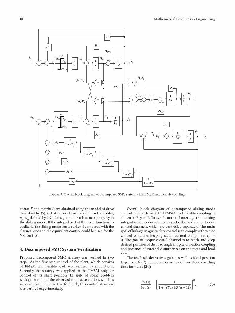
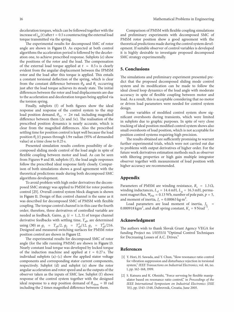


![Robust Fuzzy-Second Order Sliding Mode based …thesai.org/...Robust_Fuzzy_Second_Order_Sliding_Mode_based...Con… · Robust Fuzzy-Second Order Sliding Mode based ... [3]. Sliding-mode](https://img.pdfslide.net/doc/110x75/5b7a16407f8b9a483c8b5dce/robust-fuzzy-second-order-sliding-mode-based-robust-fuzzy-second-order-sliding.jpg)