Embed Size (px)
Citation preview

e-ISSN: 2618-575X
Available online at www.dergipark.gov.tr
INTERNATIONAL ADVANCED RESEARCHES
and
ENGINEERING JOURNAL
Journal homepage: www.dergipark.gov.tr/iarej
International
Open Access
Volume 02
Issue 01
April, 2018
* Corresponding author. Tel.: +90 537 218 1868; Fax: +90 388 311 8437.
E-mail address: [email protected]
Note: This study was presented at International Advanced Researches and Engineering Congress 2017 (IAREC’17)
Research Article
Designing autopilot system for fixed-wing flight mode of a tilt-rotor UAV in a
virtual environment: X-Plane
Mehmet Kürşat YALÇINa and Erhan ERSOYb,*
aNiğde Ömer Halisdemir University, Department of Mechatronics Engineering, Niğde, 51240, Turkey bNiğde Ömer Halisdemir University, Bor Vocational School of Higher Education, Niğde, 51700, Turkey
ARTICLE INFO ABSTRACT
Article history:
Received 28 February 2018
Revised 25 March 2018
Accepted 30 March 2018
This paper describes an autopilot system design to regulate the altitude, heading and forward speed in
the fixed-wing flight mode of the Osprey V22 VTOL (vertical takeoff and land) tilt rotor UAV
accordingly to a reference, which is generated the trajectory sub-block. X- Plane flight simulator
developed by Laminar Research, is used to test and optimize the parameter values of the autopilot
system, which is designed using feedback, feedforward and PID controllers in MATLAB / Simulink
environment (Software in the Loop- SIL). The receiver and sender blocks to perform the data
interactions between MATLAB / Simulink and X-Plane flight simulator are created in MATLAB /
Simulink environment. The receiver block is used to transfer data from the X-Plane flight simulator to
the controller, while the sender block is used to transfer control signals from the controller to the X-
Plane flight simulator program. The data communication between the two is UDP. The autopilot
system under test is embedded in the Raspberry-Pi minicomputer and a hardware-in loop (HIL) test
system created. The reaction of the control algorithm running on the Raspberry-Pi minicomputer to
the virtual sensor data generated by the X-Plane flight simulator investigated. It is observed that, the
Osprey-V22 aircraft can perform tasks autonomously in the horizontal flight mode, from the
experiments and the results obtained. This study also describes the first stage of an undergoing project
which aims to develop a robust autopilot for Osprey V22 VTOL UAV.
© 2018, Advanced Researches and Engineering Journal (IAREJ) and the Author(s).
Keywords:
Autopilot controller
Raspberry Pi Tilt-rotor
X-Plane flight simulator
1. Introduction
In the last few years, researchers have shown great
interest in the field of VTOL (Vertical Take-Off and
Landing) aerial vehicles [1]. However, most of them are
related with quadrotors. Besides these well-known platforms,
many researchers recently concentrate on the tilt rotor aerial
vehicles combining the advantages of horizontal and vertical
flights. Because these new vehicles have no conventional
design basis, many research groups build their own tilt-rotor
vehicles according to the desired technical specifications and
objectives [9]. One of them is fixed-wing VTOL UAV.
The fixed-wing VTOL UAV has a large flight envelope
than traditional VTOL UAV since it can hover, and
maneuver in 3D space like a multi-rotor as well as fly level
forward flight efficiently at high cruise speed [3]. Notable
VTOL aircrafts include the Bell XV-15, Bell-Boeing V22
and so on [4]. The development of V-22 aircraft spurred a
great research and development effort in tilt rotor
aerodynamics, flight control etc [2, 11]. Conventional
tiltrotor vehicles are mechanically complex systems since it
employs a swashplate and differential rotor tilting to control
pitch and yaw, respectively [5].
The model of tilt rotor UAV that is called Osprey V22, is
given in Figure 1. Osprey V22 is composed of fuselage, two
wings with two trailing edge flaps at each of the wing,
nacelles mounted at the wings tips, rotors mounted in front
of nacelles and horizontal stabilizer with three flaps and two
vertical fins with one rudder mounted on each fin. All
components of the aircraft are rigid. The rotors have three
blades fixed to the shaft by pitch bearing. The pitch angles of
rotor blades are controlled by swash-plates for constant
Yalçın and Ersoy, International Advanced Researches and Engineering Journal 02(01): 033-042, 2018
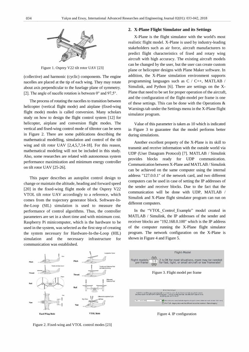
Figure 1. Osprey V22 tilt rotor UAV [23]
(collective) and harmonic (cyclic) components. The engine
nacelles are placed at the tip of each wing. They may rotate
about axis perpendicular to the fuselage plane of symmetry.
[2]. The angle of nacelle rotation is between 0° and 97,5°.
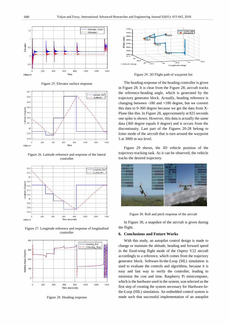
The process of rotating the nacelles to transition between
helicopter (vertical flight mode) and airplane (fixed-wing
flight mode) modes is called conversion. Many scholars
study on how to design the flight control system [12] for
helicopter, airplane and conversion flight modes. The
vertical and fixed-wing control mode of tiltrotor can be seen
in Figure 2. There are some publications describing the
mathematical modelling, simulation and control of the tilt
wing and tilt rotor UAV [2,4,5,7,14-18]. For this reason,
mathematical modeling will not be included in this study.
Also, some researches are related with autonomous system
performance maximization and minimum energy controller
on tilt rotor UAV [25-26].
This paper describes an autopilot control design to
change or maintain the altitude, heading and forward speed
[20] in the fixed-wing flight mode of the Osprey V22
VTOL tilt rotor UAV accordingly to a reference, which
comes from the trajectory generator block. Software-In-
the-Loop (SIL) simulation is used to measure the
performance of control algorithms. Thus, the controller
parameters are set in a short time and with minimum cost.
Raspberry Pi minicomputer, which is the hardware to be
used in the system, was selected as the first step of creating
the system necessary for Hardware-In-the-Loop (HIL)
simulation and the necessary infrastructure for
communication was established.
Figure 2. Fixed-wing and VTOL control modes [23]
2. X-Plane Flight Simulator and its Settings
X-Plane is the flight simulator with the world's most
realistic flight model. X-Plane is used by industry-leading
stakeholders such as air force, aircraft manufacturers to
predict flight characteristics of fixed and rotary wing
aircraft with high accuracy. The existing aircraft models
can be changed by the user, but the user can create custom
plane or helicopter designs with Plane Maker software. In
addition, the X-Plane simulation environment supports
programming languages such as C / C++, MATLAB /
Simulink, and Python [6]. There are settings on the X-
Plane that need to be set for proper operation of the aircraft,
and the configuration of the flight-model per frame is one
of these settings. This can be done with the Operations &
Warnings tab under the Settings menu in the X-Plane flight
simulator program.
Value of this parameter is taken as 10 which is indicated
in Figure 3 to guarantee that the model performs better
during simulations.
Another excellent property of the X-Plane is its skill to
transmit and receive information with the outside world via
UDP (User Datagram Protocol) [7]. MATLAB / Simulink
provides blocks ready for UDP communication.
Communication between X-Plane and MATLAB / Simulink
can be achieved on the same computer using the internal
address "127.0.0.1" of the network card, and two different
computers can be used in case of setting the IP addresses of
the sender and receiver blocks. Due to the fact that the
communication will be done with UDP, MATLAB /
Simulink and X-Plane flight simulator program can run on
different computers.
In the “VTOL_Control_Example” model created in
MATLAB / Simulink, the IP addresses of the sender and
receiver blocks are "192.168.0.100" which is the IP address
of the computer running the X-Plane flight simulator
program. The network configuration on the X-Plane is
shown in Figure 4 and Figure 5.
Figure 3. Flight model per frame
Figure 4. IP configuration
034 Yalçın and Ersoy, International Advanced Researches and Engineering Journal 02(01): 033-042, 2018

Figure 5. Port configuration
The data package of the X-Plane follows a standard
format, which requires a header and a data set sequence. The
header shown in Table 1 shows the following bytes [7]:
1. 0-3 bytes contain "DATA" characters indicating that it
is a data packet [7].
2. The 4th byte is a internal (I) code and is not used for
data transmission. It is normally defined as zero [7].
3. The bytes after the 4th byte in Table-1 are of interest
to the state of the aircraft and the input and output data to be
intervened can be defined by selecting appropriate places on
the table in Figure 6.
The parameter selection in Figure 6 can also be done with
automatically. The necessary specifications like IP number,
Port number, Waypoint data and Input/Output data, which
uses by UDP, can be written in PostLoadFcn under the
model properties of Simulink.
Figure 6. Selected parameters (input and ouput data)
Table 1 X-Plane data package pattern
3. MATLAB/Simulink Program and its Settings
Simulink is a block diagram based environment for
model-based design that simulates multi-disciplinary
systems. In Simulink environment; system level design,
simulation, automatic code generation, continuous testing,
and verification of embedded systems can be done. Simulink
offers a graphical editor, customizable block library and
solvers for modeling and simulating dynamic systems.
Simulink integrated with MATLAB, you can use MATLAB
algorithms in the model and move your simulation results to
the MATLAB environment for further analysis [8]. The
communication interface blocks are given in Figure 7. These
two blocks consist of three sub-block. These are respectively
UDP send/receive block, byte pack/unpack block and last
one is embedded MATLAB functions. There are some
settings on the Simulink that need to be set for proper
communication with X-Plane flight simulator. One of them
is IP and port configuration of UDP receive-send blocks. The
communication block configurations of Simulink are given
in Figure 8.
Figure 7. The communication blocks of sender and receiver
Figure 8. UDP communication blocks (receive and send) ports
configuration
Bytes 0 1 2 3 4 5 6 7 8 9 10 11 12 13 14 15 16 . . . . . . . . . 38 39 40 41
Value D A T A I L1 L2 L3 L4 B11 B12 B13 B14 B21 B22 B23 B24 . . . . . . . . . B81 B82 B83 B84
035 Yalçın and Ersoy, International Advanced Researches and Engineering Journal 02(01): 033-042, 2018

Figure 9. Byte unpack and pack settings
Also some settings are needed for byte pack and unpack
blocks. Byte pack block is used just to pack the data in an
array of bytes [7]. The configuration of the byte pack block
is given right side of the Figure 9. Byte unpack block is used
to unpack the data coming from X-Plane flight simulator
through the UDP Receive block. Byte unpack block
configuration is shown left side of the Figure 9. The unpack
block is configured to output 5 bytes (the header), plus a
matrix of 17 set of data [7] with 9 fields. With this
configuration, the maximum length of the message will be
617 (5 bytes header + 17 set of data * 9 fields * 4 bytes each).
This data can be seen left side in Figure 8. The input of the
byte pack block is respectively header; internal code
(generally zero) and the others are commands, which will be
send to X-Plane flight simulator with UDP send block.
The embedded function is responsible to convert
quadruple bytes into a single format floating point, which are
then converted into double format to be used by the
following blocks [7].
4. Design of the Trajectory Generator and Control
System
The Simulink model consist of four part, these are
trajectory generator block, controller block,
communication interface block, and finally visualizer
block. This Simulink model can be seen from Figure 10.
The trajectory generator block, given in detail at Figure 11,
is responsible to generate references for the aircraft in
order to perform the desired mission. For this reason, a
MATLAB function is written in Simulink. This function
consists of two basic algorithms. These are waypoint
switching and heading reference generation. The trajectory
generator block creates heading reference for the attitude
controllers in order to drive the aircraft to the next
waypoint.
Waypoints are made up from three parts, i.e., latitude,
longitude and altitude. The reference value of altitude
directly comes from the waypoint list, but the heading
reference angle must be computed. The heading angle can
be computed by using line of sight (LoS) formula, given in
Equation (1).
By using Equation (1), the reference-heading angle is
found between -180° and 180°. Bu the actual heading
angle of aircraft, which is read from X-Plane via UDP, is
between 0° and 360°. So it must be shifted to the interval,
-180° and +180°, in order to follow the shortest path. For
this reason, a short code is written in MATLAB.
Way point switching scheme is explained as follows.
A variable, called as waypoint index, holds the current
active target waypoint, and its initial value is one. When
the aircraft reach the waypoint, the waypoint index is
increased. But how the system decide a waypoint is
reached. First of all a distance variable (D) between plane
and active target waypoint is defined and computed by
using Equation (2), and the unit of D is degree. The
distance (D) is then converted from degree to meter by
using “Haversine” formula (given Appendix A). When the
distance is less than or equal to a threshold R (D ≤ R in
Figure 12), it is understood that the waypoint is reached. R
is computed by Equation (3). Here β is the bank angle and
V is the airspeed of the aircraft.
Figure 10. Simulink model of VTOL fixed-wing UAV control
system for airplane mode
Figure 11. Trajectory generator block
𝐿𝑜𝑆 = 𝑎𝑡𝑎𝑛2 [𝐿𝑜𝑛𝑤𝑝 − 𝐿𝑜𝑛𝑣𝑡𝑜𝑙
𝐿𝑎𝑡𝑤𝑝 − 𝐿𝑎𝑡𝑣𝑡𝑜𝑙
] ∗ 180/𝜋 (1)
𝐷 = √(𝐿𝑜𝑛𝑤𝑝 − 𝐿𝑜𝑛𝑣𝑡𝑜𝑙 )2
+ (𝐿𝑎𝑡𝑤𝑝 − 𝐿𝑎𝑡𝑣𝑡𝑜𝑙)2
(2)
𝑅 = 0.3048 ∗ [𝑉2
11.26 ∗ 𝑡𝑎𝑛 (𝛽)]
(3)
036 Yalçın and Ersoy, International Advanced Researches and Engineering Journal 02(01): 033-042, 2018

Figure 12. Distance between VTOL and waypoint [7]
Figure 13. Controller model at MATLAB/Simulink
The control block is designed to alter and stabilize the
VTOL aircraft altitude, heading, and forward speed in order
to track their references [20], which comes from the
waypoint list in trajectory generator block. The controller
model at the MATLAB / Simulink is given in Figure 13. The
controller block includes both feedback and feedforward
control scheme. The feedback control loop is responsible for
longitudinal, lateral direction of the aircraft.
The feed-forward terms are used to correct errors
caused by coupling movements [20-22]. The control
algorithms for the altitude and attitude, i.e., roll, pitch and
yaw, of the VTOL tiltrotor aircraft are designed based on
PID controller. All controllers contain inner and outer
loops. Heading angle is indirectly controlled by aileron
through roll angle (Figure 14). The reference roll signal is
generated accordingly the error between reference heading
angle and current heading angle. The reference-heading
angle comes from trajectory generator block. The output
of the outer loop is the reference signal for inner roll
controller and is saturated in the interval, [−45°, 45°]. The
roll controller is responsible for stabilizing the aircraft’s
roll angle. It utilizes ailerons to alter the roll angle of the
aircraft [20]. Aileron commands are sent to X-Plane and
are limited to -1 to +1 by software. All parameters of
heading controller is given in Table 2.
Figure 14. Inner and outer feedback loops for heading
controller.
Table 2. Parameters for heading controller.
𝐻𝑒𝑎𝑑𝑖𝑛𝑔 𝑃𝐼𝐷
𝐾𝑝 3.5
𝐾𝑖 1.0
𝐾𝑑 0.5
𝑅𝑜𝑙𝑙 𝑃𝐼 𝐾𝑝 0.01
𝐾𝑖 0.0002
The longitudinal control system emphasizes the altitude
and the forward speed. The altitude controller is
implemented in a cascade form (Figure 15). The output of
this controller is the reference for pitch controller inner loop.
Then the output of pitch controller is the angle of the elevator
control surface. Thus, both pitch angle and altitude of the
aircraft are ensured to be under control [20]. The maximum
pitch angle is limited to -10° to +15° by software. These
values should be transformed to X-Plane elevator control
surface commands in some limits that is -1 and +1. All
parameters for altitude controller is given in Table 3. For
forward speed control PI control is implemented and the
parameter values of the controller are Kp=0.02 and Ki=0.1,
respectively. In addition, a feed forward control gain
(Kpff=0.015) is multiplied by altitude error and then added
to the output of the forward speed controller to compensate
the loss of the altitude.
Figure 15. Inner and outer feedback loops for altitude
controller.
Table 3. Parameters for altitude controller.
𝐴𝑙𝑡𝑖𝑡𝑢𝑑𝑒 𝑃𝐼𝐷
𝐾𝑝 0.2
𝐾𝑖 0.02
𝐾𝑑 0.01
𝑃𝑖𝑡𝑐ℎ 𝑃𝐼𝐷
𝐾𝑝 0.1
𝐾𝑖 0.1
𝐾𝑑 0.01
037 Yalçın and Ersoy, International Advanced Researches and Engineering Journal 02(01): 033-042, 2018

5. Implementation and Application Results
In this study, a laptop, a PC and Raspberry Pi are used as
to develop control architecture, to run flight dynamics and to
implement controller respectively, as shown in Figure 16.
The Raspberry Pi is a low cost, credit-card sized computer
that plugs into a computer monitor or TV, and uses a standard
keyboard and mouse. It is a capable little device that enables
people of all ages to explore computing, and to learn how to
program in languages like C, Scratch and Python [24]. The
Raspberry Pi can be seen on Figure 17.
Simulink Support Package for Raspberry Pi Hardware
enables to create and run Simulink models on Raspberry Pi
hardware. The support package includes a library of
Simulink blocks for configuring and accessing I/O
peripherals and communication interfaces. After creating
Simulink model, it can be simulate, tune algorithm
parameters until get it just right, and download the completed
algorithm for standalone execution on the device. With the
MATLAB Function block, MATLAB code is incorporated
into the Simulink model. With Simulink support package for
Raspberry Pi, the algorithm developed in Simulink can be
deployed to the Raspberry Pi using automatic code
generation [19].
At the end of this process, an embedded control system was
made and autopilot control system is then run on the
Raspberry Pi in a standalone fashion.
Figure 16. Implementation of autopilot test platform
Communication between Raspberry Pi and X-Plane
occurs through ethernet port using via UDP.
The parameter of the Waypoint List is given in Table 4
for testing the autopilot performance. The list consist of five
waypoints. First and last is the same point but the altitude is
different each other. We requested to move around the
waypoint by coming to the fifth waypoint through the
transition points from the autopilot. For this reason, the
simulation is started by using “Get Me Lost” function of the
X-Plane flight simulator. In Figure 18, the simulated flight
path according to the “Waypoint List” data is given on the
Google Maps. The straight lines show the references and
dashed line shows the real path of the aircraft. In addition,
the 3D flight path on X-Plane is also given in Figure 19. The
result, which is taken in Figure 18-19, represents one tour on
the route. The responses of the controller for the flight path
are given in Figure 20-29. In the Figure 20, the altitude
behavior of the controller is given.
Table 4. Waypoint List
Waypoints
List Latitude (°) Longitude (°)
Altitude
(m)
Waypoint_1 37.938240 34.628514 2500
Waypoint_2 37.867186 34.224914 2750
Waypoint_3 38.194536 33.897176 3000
Waypoint_4 38.608634 33.510110 3000
Waypoint_5 37.938240 34.628514 3000
The blue line represents the altitude reference and dashed
red line is altitude response of the controller with respect to
sea level in meters. Some overshoot occurs instant the
switching of waypoint, because the lift of the wing is
decreasing. For this reason, pitch of the aircraft increases to
maintain the altitude and airspeed increases for a short time.
Figure 21 shows the airspeed response of the all flight path.
The maximum overshoot of the airspeed is less than 6
percent, and then airspeed is decreased by the controller
and tracks the reference value.
Figure 17. Raspberry Pi 3
Figure 18. Flight path for waypoint list on X-Plane
038 Yalçın and Ersoy, International Advanced Researches and Engineering Journal 02(01): 033-042, 2018

Figure 20. Altitude response
Figure 21. Forward speed response
The solid blue lines of the Figure 22, 23 and 28
represent the reference values of the pitch, roll and
heading, respectively. Dashed red lines are the response of
the aircraft. The pitch value is limited between -10° and
+15° and the roll value is limited between -45° and +45°.
The heading angle is changing between -180° and +180°.
In airplane mode due to a combination of having zero
angle of incidence in the wing and the thrust line being
above the centerline of the aircraft, the pitch reference of
the Osprey V22 about 7 degrees. The aileron and elevator
command and surface deflections are given through
between 0 and 1400 sec in Figure 24-25. It is clear from
the Figure 24, aircraft tracks the aileron reference
command, which is generated by the inner loop of the roll
controller block.
Elevator command and surface response looks like not
tracking each other in Figure 25. The reason is related the
elevator trim value, which is produced with altitude error
by a cross coupling gain.
Figure 26-28 is related with heading response of the
heading controller. The reference latitude and longitude
values and the controller response for these values are
given in Figure 26 and 27, respectively. In addition, the
detailed reference values of latitude and longitude can also
be found at Table 4.
Figure 19. 3D Flight path for waypoint list on X-Plane
Figure 22. Pitch response
Figure 23. Roll response
Figure 24. Aileron surface response
039 Yalçın and Ersoy, International Advanced Researches and Engineering Journal 02(01): 033-042, 2018
The heading response of the heading controller is given
in Figure 28. It is clear from the Figure 28; aircraft tracks
the reference-heading angle, which is generated by the
trajectory generator block. Actually, heading reference is
changing between -180 and +180 degree, but we convert
this data to 0-360 degree because we get the data from X-
Plane like this. In Figure 28, approximately at 825 seconds
one spike is shown. However, this data is actually the same
data (360 degree equals 0 degree) and it occurs from the
discontinuity. Last part of the Figures 20-28 belong to
loiter mode of the aircraft that is turn around the waypoint
5 at 3000 m sea level.
Figure 29 shows, the 3D vehicle position of the
trajectory-tracking task. As it can be observed, the vehicle
tracks the desired trajectory.
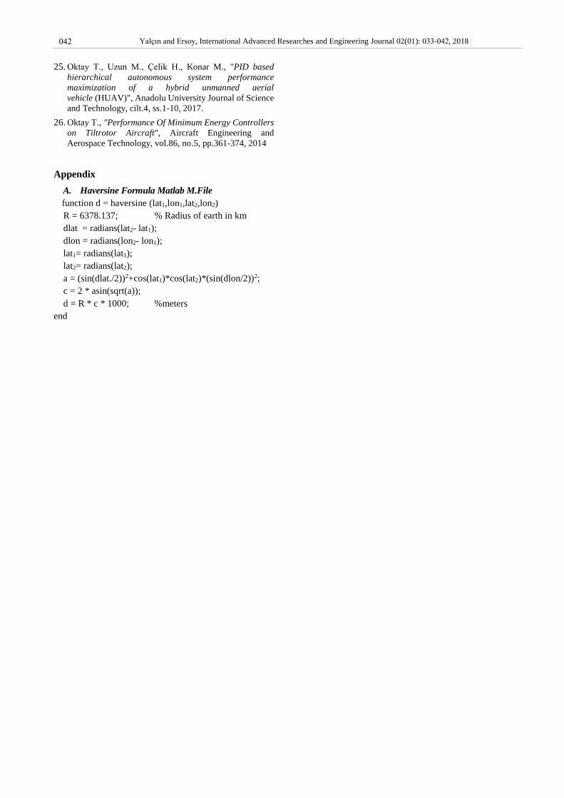
Figure 30. Roll and pitch response of the aircraft
In Figure 30, a snapshot of the aircraft is given during
the flight.
6. Conclusions and Future Works
With this study, an autopilot control design is made to
change or maintain the altitude, heading and forward speed
in the fixed-wing flight mode of the Osprey V22 aircraft
accordingly to a reference, which comes from the trajectory
generator block. Software-In-the-Loop (SIL) simulation is
used to evaluate the controls and algorithms, because it is
easy and fast way to verify the controller, leading to
minimize the cost and time. Raspberry Pi minicomputer,
which is the hardware used in the system, was selected as the
first step of creating the system necessary for Hardware-In-
the-Loop (HIL) simulation. An embedded control system is
made such that successful implementation of an autopilot
Figure 25. Elevator surface response
Figure 26. Latitude reference and response of the lateral
controller
Figure 27. Longitude reference and response of longitudinal
controller
Figure 28. Heading response
Figure 29. 3D Flight path of waypoint list
040 Yalçın and Ersoy, International Advanced Researches and Engineering Journal 02(01): 033-042, 2018

system is then run on the Raspberry Pi as a standalone
application. Communication between Raspberry Pi and X-
Plane is provided through their Ethernet port using UDP.
The future work will be based on developing robust
controller, instead of classical PID, for vertical take-off
/landing and transition mode for Osprey V22 aircraft. Then,
a platform will be built, which aid autopilot systems study
and design. This platform will allow to us to monitor the
aircraft responses for a designed autopilot system with high
degree of realism.
Acknowledgment
This work is supported by the Research Project Unit of
Niğde Ömer Halisdemir University under Research Project
(project no: FEB 2016/28 DOKTEP), Turkey.
Nomenclature
VTOL : Vertical Take-off and Landing
UAV : Unmanned Air Vehicle
References
1. Escareño, J., Salazar, S. and Lozano, R., Modelling and
Control of a Convertible VTOL Aircraft. Proceedings of
the 45th IEEE Conference on Decision & Control, San
Diego, CA, USA, 2006:p 69-74.
2. 43r5Miller, M. and Narkiewicz, J., The application of
General Model of Moving Object for Tiltrotor Stability
Analysis, Journal of Theoretical and Applied
Mechanics, Warsaw, 2006, Vol. 44 No. 4, p 881-906
3. Malang, Y., Design and control a Vertical Takeoff and
Landing Fixed-Wing UAV, Master of applied Science
2016. University of Toronto.
4. Sanchez, A., Escareño, J., Garcia, O. and Lozano, R.,
Autonomous Hovering of a Noncyclic Tiltrotor UAV:
Modeling, Control and Implementation. Proceedings of
the 17th World Congress The International Federation of
Automatic Control Seoul, Korea, 2008. p 803-808.
5. Yongzhong, L., Danping, Y. and David, L., Parameter
Estimation Of Vertical Takeoff And Landing Aircrafts By
Using A PID Controlling Particle Swarm Optimization
Algorithm, Applied Intelligence, 2016. 44: p 793-815.
6. Meyer, A. X-Plane 9/10. X-Plane Operation Manual,
2011.
7. Bittar, A., Figuereido, H.V., Guimaraes, P.A. and
Mendes, A. C., Guidance Software-in-The-Loop
Simulation Using X-Plane and Simulink for UAVs, 2014
International Conference on Unmanned Aircraft Systems
(ICUAS), 2014. Orlando, FL, USA. p 993-1002
8. Figes Engineering, Simulink Technical Source,
http://www.figes.com.tr/matlab/E-Technical-Kit.
Simulink / index.html
9. Öner, K.T., Çetinsoy, E., Sırımoğlu, E., Hançer, C., Ünel,
M., Akşit, F., Gülmez, K. and Kandemir, İ.,
Mathematical Modeling and Vertical Flight Control of a
Tilt-Wing UAV, Turk J Elec Eng & Comp Sci, Vol.20,
No.1, 2012. p 149-157.
10. McVeigh, M.A., Nagib, H., Wood, T. Kiedaisch, J.
Stalker, A. and Wygnanski, I., Model & Full Scale
Tiltrotor Download Reduction Tests Using Active Flow
Control, 60th Annual Forum, Paner No 1, Baltimore,
2004. P 181-192.
11. J.M. Weakley, K.M. Kleinhesselink, D.H. Mason and
D.G. Mitchell, Simulation Evaluation of V-22 Degraded-
Mode Flying Qualities, 59 AHS Forum 2003, Paper No
135, Phoenix, AZ, USA, 2003.
12. Yonghua, F. and Jun, Y., Design of Tiltrotor Flight
Control System Using Optical Control, Proceedings of the
26th Chinese Control Conference 2007, Zhangjiajie,
Hunan, China, 2007. p 687-691
13. Muraoka, K., Okada, N., Kubo, D. and Sato, M.,
Transition Flight of Quad Tilt Wing VTOL UAV, 28th
International Congress Of The Aeronautical Sciences,
2012. p 1-10.
14. Yüksek, B., Vuruskan, A., Özdemir, U., Yükselen, A.
and İnalhan, G., Transition Flight Modeling of a Fixed-
Wing VTOL UAV, Journal of Intelligent & Robotics
Systems, vol 81, No. 1 International Publishing, 2016. p
1-23
15. Warsi, F., Hazry, D., Ahmed, S., Joyo, M. and et.al,
Yaw,Pitch and Roll Controller Design For Fixed-Wing
UAV under Uncertainty and Perturbed Condition, Signal
Processing and its Applications, IEEE 10th International
Colloquium, 2014. p 151-156.
16. Casau, P., Cabecinhas, D. and Silvestre, C., Hybrid
Control Strategy for Autonomous Transition Flight of a
Fixed –Wing Aircraft, IEEE Transactions on Control
Systems Technology, vol 21, No.6 IEEE, 2013. p 2194-
2211.
17. Papachristos, C., Alexis, K., Nikolakopoulos, G. and
Tzes, A., Model Predictive Attitude Control of an
Unmanned Tilt-Rotor Aircraft, IEEE International
Symposium, Gdansk, Poland, 2011. p 922-927
18. Riberio, R.L. and Oliveria, N.F., Using Autopilot
Controllers Test Platform Using MATLAB/Simulink and
X-Plane, 40th Frontiers in Education Conference (FIE),
Washington, DC, USA, 2010.
19.
20. Bittar, A. and Oliveira, N. M. F., Central Processing Unit
for an Autopilot: Description and Hardware-In-the-Loop
Simulation, J Intell Robot Syst, 2013. Vol. 70. p 557-574
21. Andrievsky, B. and Fradkov, A., Combined Adaptive
Autopilot for an UAV Flight Control. In 2002 IEEE
International Conference on Control Applications,2002. p.
290–291.
22. Wu, H.Y., Zhou, Z.Y. and Sun, D., Autonomous Hovering
Control and Test for Micro Air Vehicle. In Proceedings of
the International Conference on Robotics and Automation,
Taiwan, 2003 p. 528–533.
23.
24.
041 Yalçın and Ersoy, International Advanced Researches and Engineering Journal 02(01): 033-042, 2018
https://www.globalsecurity.org/military/systems/aircraft/
v-22-flt-cntrl.htm [Available: 2018 29 June]https://www.raspberrypi.org/help/what-%20is-a-
raspberry-pi/ [Available: 2018 29 June]
MathWorks, Raspberry Pi Programming with MATLAB
and Simulink,
https://www.mathworks.com/discovery/raspberry-pi-
programming -matlab-simulink.html
25. Oktay T., Uzun M., Çelik H., Konar M., "PID based
hierarchical autonomous system performance
maximization of a hybrid unmanned aerial
vehicle (HUAV)", Anadolu University Journal of Science
and Technology, cilt.4, ss.1-10, 2017.
26. Oktay T., "Performance Of Minimum Energy Controllers
on Tiltrotor Aircraft", Aircraft Engineering and
Aerospace Technology, vol.86, no.5, pp.361-374, 2014
Appendix
A. Haversine Formula Matlab M.File
function d = haversine (lat1,lon1,lat2,lon2)
R = 6378.137; % Radius of earth in km
dlat = radians(lat2- lat1);
dlon = radians(lon2- lon1);
lat1= radians(lat1);
lat2= radians(lat2);
a = (sin(dlat./2))2+cos(lat1)*cos(lat2)*(sin(dlon/2))2;
c = 2 * asin(sqrt(a));
d = R * c * 1000; %meters
end
042 Yalçın and Ersoy, International Advanced Researches and Engineering Journal 02(01): 033-042, 2018