Embed Size (px)
Citation preview
Research ArticleDual Y-Shaped Monopole Antenna for Dual-BandWLAN/WiMAX Operations
Huiqing Zhai, Qiqiang Gao, Zhihui Ma, and Changhong Liang
National Key Laboratory of Antennas and Microwave Technology, School of Electronic Engineering, Xidian University,No. 2 South Taibai Road, Xi’an, Shaanxi 710071, China
Correspondence should be addressed to Huiqing Zhai; [email protected]
Received 13 January 2014; Revised 23 April 2014; Accepted 1 June 2014; Published 15 June 2014
Academic Editor: Ahmed A. Kishk
Copyright © 2014 Huiqing Zhai et al. This is an open access article distributed under the Creative Commons Attribution License,which permits unrestricted use, distribution, and reproduction in any medium, provided the original work is properly cited.
A dual-band design of monopole antenna with two coupled Y-shaped strips for WLAN/WiMAX applications is presented. By theintroduction of dual Y-shaped strips, two separated impedance bandwidths of 22.4% (3.28∼4.10GHz) and 19.2% (4.90∼5.94GHz)can be obtained to meet the specifications of the WLAN/WiMAX communication band applications. The proposed antenna issuccessfully simulated, designed, andmeasured, demonstrating the matched impedance and good radiation characteristics with anoverall dimension of 17.7 × 26 × 1mm3.
1. Introduction
The rapid development of wireless communication urgesthe need of antennas covering multiple bands with goodradiation characteristics. Thus, many researchers have beingpaying much attention to design this kind of antennas,such as in [1–9]. In [1], by the presence of an L-shapedparasitic strips, three resonant modes of the antenna for the2.6/3.5/5.5 GHz-bands can be excited to meet the WiMAXsystem. By introducing dual U-shaped strips, multiresonantmodes for WiMAX applications are proposed in [2]. In[3], with inclusion of an additional small radiation patch,a dual-band antenna designed from 3.1 to 10.6GHz outof the band 5.0-6.0GHz can be achieved. Two stacked T-shaped monopoles antenna was presented for 2.4/5.2 GHzWLAN-bands applications in [4]. A microsrip-fed dual U-shaped printedmonopole antenna design for 2.4 and 5.8GHzcommunication bands was introduced in [5]. A novel copla-nar waveguide (CPW) antenna was proposed for dual-bandWLAN applications in [6]. In [7], by etching an n-shaped sloton the radiating element, a novel coplanarwaveguide- (CPW-) fed printed monopole antenna was proposed. In [8–10],other three different dual-band antennas were also presentedby driven strip, modified half-bowtie radiating element, and
variable frequency band-notch characteristic, respectively.Though new structures or designs have been given in aboveliteratures, some shortcomings still exist to a certain extend.For the antennas in [1, 2, 4–6], the working bands cannotbe separately adjusted flexibly. The structures in [3, 7] aredesigned for tunable notches, which may lead to inconstantimpedance bandwidth of each operation band. Meanwhile,antennas in [8–10] have complex constructions which willsomehow limit their low-cost terminal design in large-scalewireless communications. Besides, the overall dimensions ofantenna are with large size, for example, 100 × 100 × 56mm3in [11], 32.5 × 20 × 1mm3 in [12], and 30 × 26 × 1.6mm3 in[13].
In this paper, a new design of dual-band monopole ante-nna with two coupled Y-shaped strips for WLAN/WiMAX applications is proposed. With the usage oftwo Y-shaped strips, both 5.2/5.8 GHz WLAN bands and3.6/5.5 GHz WiMAX bands can be obtained. Specially, thepresented antenna has the advantages of small size, simplestructure, and steady gain. At the same time, both workingbands can be separately adjusted by simple central angle ofthe up Y-shaped strip. The simulated and measured resultsshow that the antenna can effectively cover two separatedimpedance bandwidths including 820MHz (3.28∼4.10GHz)
Hindawi Publishing CorporationInternational Journal of Antennas and PropagationVolume 2014, Article ID 481918, 5 pageshttp://dx.doi.org/10.1155/2014/481918
2 International Journal of Antennas and Propagation
x y
z
126
14.4
13.5
17.7
2.7
8.1
10.8
9.310
Gro
und
plan
e(b
otto
m si
de)
𝜀r=
2.65
(Units: mm)
85.8∘
79.6∘
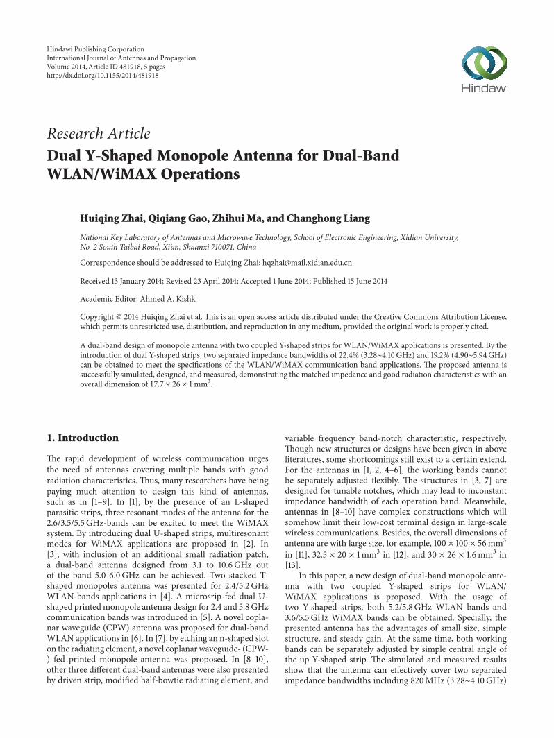
Figure 1: The geometry of the presented dual-band antenna.
Figure 2: The fabricated prototype of the presented antenna.
−40
−30
−20
−10
0
S11
(dB)
3 4 5 6 7Frequency (GHz)
Simulated resultsMeasured results
3.28 4.10 4.90 5.94
Figure 3: The simulated and measured return loss results of theproposed antenna.
3.5000e + 001
3.2557e + 001
3.0114e + 001
2.7672e + 001
2.5229e + 001
2.2786e + 001
2.0343e + 001
1.7900e + 001
1.5458e + 001
1.3015e + 001
1.0572e + 001
8.1291e + 000
5.6863e + 000
3.2435e + 000
8.0072e − 001
Jsurf [A per m]
(a)
3.5000e + 001
3.2557e + 001
3.0114e + 001
2.7672e + 001
2.5229e + 001
2.2786e + 001
2.0343e + 001
1.7900e + 001
1.5458e + 001
1.3015e + 001
1.0572e + 001
8.1291e + 000
5.6863e + 000
3.2435e + 000
8.0072e − 001
Jsurf [A per m]
(b)
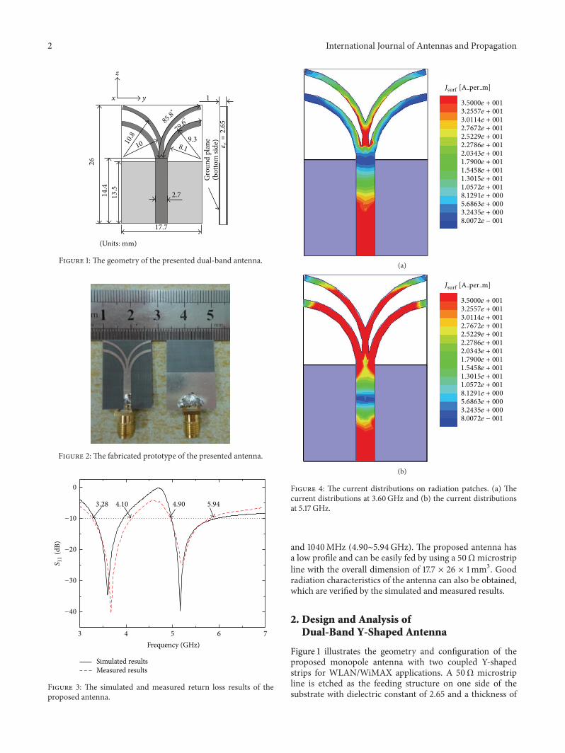
Figure 4: The current distributions on radiation patches. (a) Thecurrent distributions at 3.60GHz and (b) the current distributionsat 5.17 GHz.
and 1040MHz (4.90∼5.94GHz). The proposed antenna hasa low profile and can be easily fed by using a 50Ωmicrostripline with the overall dimension of 17.7 × 26 × 1mm3. Goodradiation characteristics of the antenna can also be obtained,which are verified by the simulated and measured results.
2. Design and Analysis ofDual-Band Y-Shaped Antenna
Figure 1 illustrates the geometry and configuration of theproposed monopole antenna with two coupled Y-shapedstrips for WLAN/WiMAX applications. A 50Ω microstripline is etched as the feeding structure on one side of thesubstrate with dielectric constant of 2.65 and a thickness of
International Journal of Antennas and Propagation 3
−40
−30
−20
−10
0
S11
(dB)
3 4 5 6 7Frequency (GHz)
With two stripsWith up stripWith down strip
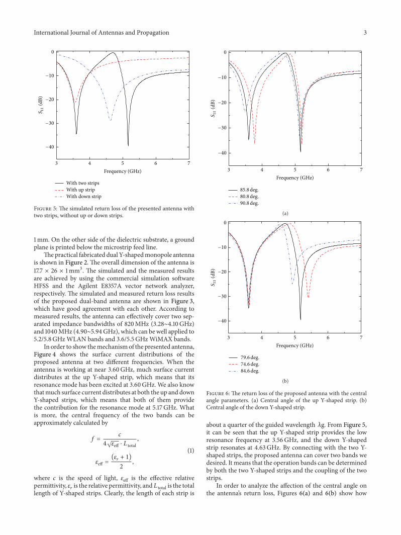
Figure 5: The simulated return loss of the presented antenna withtwo strips, without up or down strips.
1mm. On the other side of the dielectric substrate, a groundplane is printed below the microstrip feed line.
Thepractical fabricated dual Y-shapedmonopole antennais shown in Figure 2. The overall dimension of the antenna is17.7 × 26 × 1mm3. The simulated and the measured resultsare achieved by using the commercial simulation softwareHFSS and the Agilent E8357A vector network analyzer,respectively. The simulated and measured return loss resultsof the proposed dual-band antenna are shown in Figure 3,which have good agreement with each other. According tomeasured results, the antenna can effectively cover two sep-arated impedance bandwidths of 820MHz (3.28∼4.10GHz)and 1040MHz (4.90∼5.94GHz), which can be well applied to5.2/5.8 GHz WLAN bands and 3.6/5.5 GHz WiMAX bands.
In order to show themechanismof the presented antenna,Figure 4 shows the surface current distributions of theproposed antenna at two different frequencies. When theantenna is working at near 3.60GHz, much surface currentdistributes at the up Y-shaped strip, which means that itsresonance mode has been excited at 3.60GHz. We also knowthatmuch surface current distributes at both the up and downY-shaped strips, which means that both of them providethe contribution for the resonance mode at 5.17 GHz. Whatis more, the central frequency of the two bands can beapproximately calculated by
𝑓 =
𝑐
4√𝜀eff ⋅ 𝐿 total
,
𝜀eff =(𝜀
𝑟+ 1)
2
,
(1)
where 𝑐 is the speed of light, 𝜀eff is the effective relativepermittivity, 𝜀
𝑟is the relative permittivity, and𝐿 total is the total
length of Y-shaped strips. Clearly, the length of each strip is
−40
−30
−20
−10
0
S11
(dB)
3 4 5 6 7Frequency (GHz)
85.8deg.80.8 deg.90.8deg.
(a)
3 4 5 6 7Frequency (GHz)
−40
−30
−20
−10
0
S11
(dB)
79.6deg.74.6deg.84.6deg.
(b)
Figure 6: The return loss of the proposed antenna with the centralangle parameters. (a) Central angle of the up Y-shaped strip. (b)Central angle of the down Y-shaped strip.
about a quarter of the guided wavelength 𝜆g. From Figure 5,it can be seen that the up Y-shaped strip provides the lowresonance frequency at 3.56GHz, and the down Y-shapedstrip resonates at 4.63GHz. By connecting with the two Y-shaped strips, the proposed antenna can cover two bands wedesired. It means that the operation bands can be determinedby both the two Y-shaped strips and the coupling of the twostrips.
In order to analyze the affection of the central angle onthe antenna’s return loss, Figures 6(a) and 6(b) show how
4 International Journal of Antennas and Propagation
0
−10
−20
−10
0
030
60
90
120
150180
210
240
270
300
330
E plane (sim.)H plane (sim.)
E plane (mea.)H plane (mea.)
(a)
0
−10
−20
−10
0
030
60
90
120
150
180
210
240
270
300
330
E plane (sim.)H plane (sim.)
E plane (mea.)H plane (mea.)
(b)
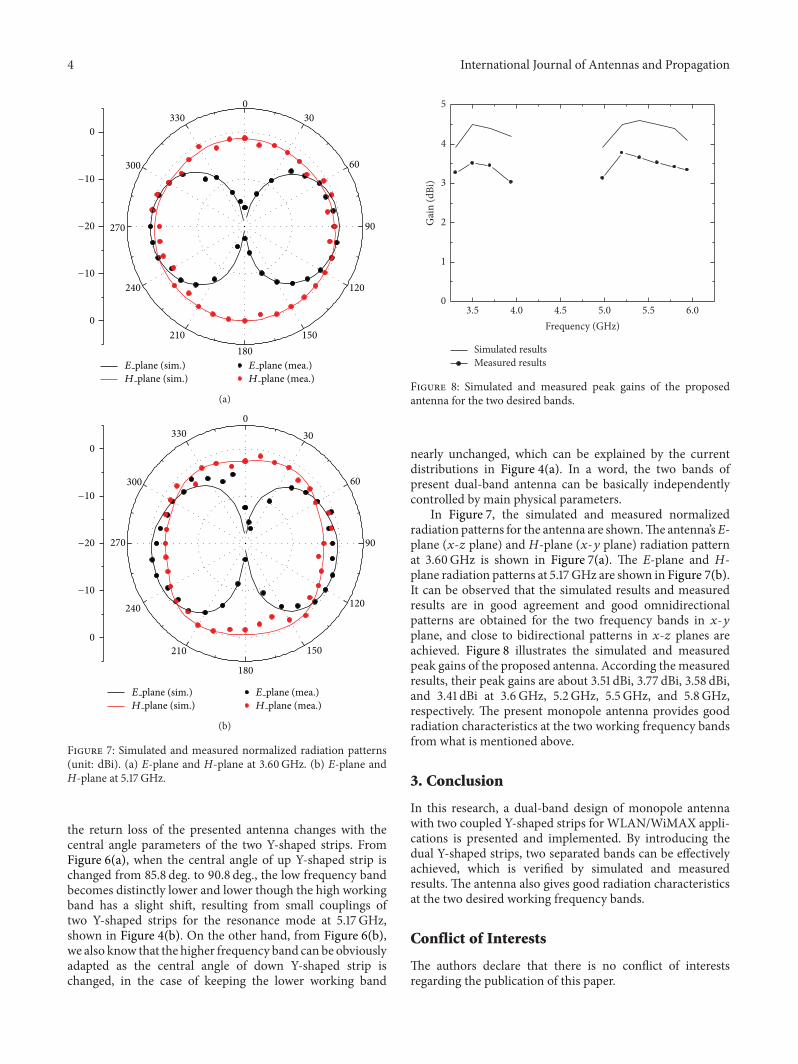
Figure 7: Simulated and measured normalized radiation patterns(unit: dBi). (a) E-plane and H-plane at 3.60GHz. (b) E-plane andH-plane at 5.17 GHz.
the return loss of the presented antenna changes with thecentral angle parameters of the two Y-shaped strips. FromFigure 6(a), when the central angle of up Y-shaped strip ischanged from 85.8 deg. to 90.8 deg., the low frequency bandbecomes distinctly lower and lower though the high workingband has a slight shift, resulting from small couplings oftwo Y-shaped strips for the resonance mode at 5.17 GHz,shown in Figure 4(b). On the other hand, from Figure 6(b),we also know that the higher frequency band can be obviouslyadapted as the central angle of down Y-shaped strip ischanged, in the case of keeping the lower working band
0
1
2
3
4
5
Gai
n (d
Bi)
3.5 4.0 4.5 5.0 5.5 6.0Frequency (GHz)
Simulated resultsMeasured results
Figure 8: Simulated and measured peak gains of the proposedantenna for the two desired bands.
nearly unchanged, which can be explained by the currentdistributions in Figure 4(a). In a word, the two bands ofpresent dual-band antenna can be basically independentlycontrolled by main physical parameters.
In Figure 7, the simulated and measured normalizedradiation patterns for the antenna are shown.The antenna’sE-plane (𝑥-𝑧 plane) and H-plane (𝑥-𝑦 plane) radiation patternat 3.60GHz is shown in Figure 7(a). The E-plane and H-plane radiation patterns at 5.17 GHz are shown in Figure 7(b).It can be observed that the simulated results and measuredresults are in good agreement and good omnidirectionalpatterns are obtained for the two frequency bands in 𝑥-𝑦plane, and close to bidirectional patterns in 𝑥-𝑧 planes areachieved. Figure 8 illustrates the simulated and measuredpeak gains of the proposed antenna. According the measuredresults, their peak gains are about 3.51 dBi, 3.77 dBi, 3.58 dBi,and 3.41 dBi at 3.6GHz, 5.2 GHz, 5.5 GHz, and 5.8GHz,respectively. The present monopole antenna provides goodradiation characteristics at the two working frequency bandsfrom what is mentioned above.
3. Conclusion
In this research, a dual-band design of monopole antennawith two coupled Y-shaped strips for WLAN/WiMAX appli-cations is presented and implemented. By introducing thedual Y-shaped strips, two separated bands can be effectivelyachieved, which is verified by simulated and measuredresults. The antenna also gives good radiation characteristicsat the two desired working frequency bands.
Conflict of Interests
The authors declare that there is no conflict of interestsregarding the publication of this paper.

International Journal of Antennas and Propagation 5
Acknowledgments
This work is supported by the NSFC under Contract no.61101066, the Natural Science Basic Research Plan in ShaanxiProvince of China under Grant no. 2014JM8316, Fundamen-tal Research Funds for the Central Universities (JB140232),Huawei Innovation Research Program, and Foundationfor the Returned Overseas Chinese Scholars in ShaanxiProvince.
References
[1] J.-H. Lu and B.-J. Huang, “Planar multi-band monopoleantenna with L-shaped parasitic strip for WiMAX application,”Electronics Letters, vol. 46, no. 10, pp. 671–672, 2010.
[2] J.-H. Lu and W.-C. Chou, “Planar dual U-shaped monopoleantenna with multiband operation for IEEE 802.16e,” IEEEAntennas andWireless Propagation Letters, vol. 9, pp. 1006–1009,2010.
[3] K.G.Thomas andM. Sreenivasan, “A simple ultrawideband pla-nar rectangular printed antenna with band dispensation,” IEEETransactions on Antennas and Propagation, vol. 58, no. 1, pp. 27–34, 2010.
[4] Y.-L. Kuo and K.-L. Wong, “Printed double-T monopoleantenna for 2.4/5.2 Ghz dual-band WLAN operations,” IEEETransactions on Antennas and Propagation, vol. 51, no. 9, pp.2187–2192, 2003.
[5] I.-F. Chen and C.-M. Peng, “Microstrip-fed dual-U-shapedprinted monopole antenna for dual-band wireless communica-tion applications,”Electronics Letters, vol. 39, no. 13, pp. 955–956,2003.
[6] K. G. Thomas and M. Sreenivasan, “Compact CPW-fed dual-band antenna,” Electronics Letters, vol. 46, no. 1, pp. 13–14, 2010.
[7] S. T. Fan, Y. Z. Yin,W. Hu, K. Song, and B. Li, “Novel CPW-FEDprinted monopole antenna with an n-shaped slot for dual-bandoperations,” Microwave and Optical Technology Letters, vol. 54,no. 1, pp. 240–242, 2012.
[8] K.-L. Wong and T.-W. Kang, “GSM850/900/1800/1900/UMTSprinted monopole antenna for mobile phone application,”Microwave and Optical Technology Letters, vol. 50, no. 20, pp.3192–3198, 2008.
[9] Y. J. Cho, K. H. Kim, D. H. Choi, S. S. Lee, and S.-O. Park, “Aminiature UWB planar monopole antenna with 5-GHz band-rejection filter and the time-domain characteristics,” IEEETransactions on Antennas and Propagation, vol. 54, no. 5, pp.1453–1460, 2006.
[10] M.Ojaroudi, G. Ghanbari, N. Ojaroudi, andC. Ghobadi, “Smallsquare monopole antenna for UWB applications with variablefrequency band-notch function,” IEEE Antennas and WirelessPropagation Letters, vol. 8, pp. 1061–1064, 2009.
[11] H. J. Zhou, Q. Z. Liu, Y. Z. Yin, and W. B. Wei, “Study of theband-notch function for swallow-tailed planar monopoleantennas,” Progress in Electromagnetics Research, vol. 77, pp. 55–65, 2007.
[12] J. Ma, Y. Z. Yin, S. G. Zhou, and L. Y. Zhao, “A new ultra-wide-band microstrip-line fed antenna with 3.5/5.5 GHz dual band-notch function,” Progress In Electromagnetics Research Letters,vol. 7, pp. 79–85, 2009.
[13] Q.-X. Chu and Y.-Y. Yang, “3.5/5.5 GHz dual band-notch ultra-wideband antenna,” Electronics Letters, vol. 44, no. 3, pp. 172–174, 2008.

International Journal of
AerospaceEngineeringHindawi Publishing Corporationhttp://www.hindawi.com Volume 2014
RoboticsJournal of
Hindawi Publishing Corporationhttp://www.hindawi.com Volume 2014
Hindawi Publishing Corporationhttp://www.hindawi.com Volume 2014
Active and Passive Electronic Components
Control Scienceand Engineering
Journal of
Hindawi Publishing Corporationhttp://www.hindawi.com Volume 2014
International Journal of
RotatingMachinery
Hindawi Publishing Corporationhttp://www.hindawi.com Volume 2014
Hindawi Publishing Corporation http://www.hindawi.com
Journal ofEngineeringVolume 2014
Submit your manuscripts athttp://www.hindawi.com
VLSI Design
Hindawi Publishing Corporationhttp://www.hindawi.com Volume 2014
Hindawi Publishing Corporationhttp://www.hindawi.com Volume 2014
Shock and Vibration
Hindawi Publishing Corporationhttp://www.hindawi.com Volume 2014
Civil EngineeringAdvances in
Acoustics and VibrationAdvances in
Hindawi Publishing Corporationhttp://www.hindawi.com Volume 2014
Hindawi Publishing Corporationhttp://www.hindawi.com Volume 2014
Electrical and Computer Engineering
Journal of
Advances inOptoElectronics
Hindawi Publishing Corporation http://www.hindawi.com
Volume 2014
The Scientific World JournalHindawi Publishing Corporation http://www.hindawi.com Volume 2014
SensorsJournal of
Hindawi Publishing Corporationhttp://www.hindawi.com Volume 2014
Modelling & Simulation in EngineeringHindawi Publishing Corporation http://www.hindawi.com Volume 2014
Hindawi Publishing Corporationhttp://www.hindawi.com Volume 2014
Chemical EngineeringInternational Journal of Antennas and
Propagation
International Journal of
Hindawi Publishing Corporationhttp://www.hindawi.com Volume 2014
Hindawi Publishing Corporationhttp://www.hindawi.com Volume 2014
Navigation and Observation
International Journal of
Hindawi Publishing Corporationhttp://www.hindawi.com Volume 2014
DistributedSensor Networks
International Journal of