Embed Size (px)
Citation preview
Research ArticleExtended Calibration Technique of a Four-Hole Probe forThree-Dimensional Flow Measurements
Suresh Munivenkatareddy and Nekkanti Sitaram
Thermal Turbomachines Laboratory Department of Mechanical Engineering Indian Institute of Technology MadrasChennai 600 036 India
Correspondence should be addressed to Suresh Munivenkatareddy suremreddygmailcom
Received 9 December 2015 Revised 2 April 2016 Accepted 25 May 2016
Academic Editor Awatef Hamed
Copyright copy 2016 S Munivenkatareddy and N Sitaram This is an open access article distributed under the Creative CommonsAttribution License which permits unrestricted use distribution and reproduction in any medium provided the original work isproperly cited
The present paper reports the development and nonnulling calibration technique to calibrate a cantilever type cylindrical four-hole probe of 254mm diameter to measure three-dimensional flows The probe is calibrated at a probe Reynolds number of 9525The probe operative angular range is extended using a zonal method by dividing into three zones namely center left and rightzone Different calibration coefficients are defined for each zone The attainable angular range achieved using the zonal method isplusmn60 degrees in the yaw plane and minus50 to +30 degrees in the pitch plane Sensitivity analysis of all the four calibration coefficientsshows that probe pitch sensitivity is lower than the yaw sensitivity in the center zone and extended left and right zones have lowersensitivity than the center zone In addition errors due to the data reduction program for the probe are presented The errors arefound to be reasonably small in all the three zones However the errors in the extended left and right zones have slightly largermagnitudes compared to those in the center zone
1 Introduction
Turbomachinery flows are highly unsteady and three dimen-sional The key to further improvement in turbomachin-ery is through understanding the three-dimensional flowthrough their components such as rotors and stators Suchthree dimensional flows encountered in turbomachines canbe analyzed by flow visualization computational methodsand direct measurements of the flow field However flowvisualization has limitations since the techniques serve onlyto the locate regions of interest in the flow and computationalmethods are expensive and are not fully reliable Only directmeasurement of the flow can provide quantitative data offlow parameters such as total and static pressures velocitiesand Mach numbers and flow angles to understand the flowbetter Pressure probes are one of the options to measurethe flow parameters directly by inserting them into the flowfield of turbomachines [1] The prominent advantages ofpressure probe techniques over hot-wire probes and optical
techniques are their ability to measure pressure within theflow robustness simplicity and cost effectiveness
Since Henri Pitot used a simple bent tube to measurethe total pressure in fluid flow in 1732 a broad variety ofpneumatic probes have been developed over years RecentlyTelionis et al [2] have made a comprehensive survey of mul-tihole pressure probes for flow measurements Dependingon the velocity range angular range required and types ofturbomachinery specific probe head geometries have beendesigned All these probes can determine flow quantitiessuch as total and static pressure flow angles or Machnumbers by measuring the pressures at different locationson the probe head The minimum number of pressure holeson the pressure probe depends on the dimensionality ofthe flow field measured A simple pressure probe used tomeasure two-dimensional flows has three pressure holes [3]while the minimum number of holes to measure three-dimensional flows is four Multihole pressure probes of four[4] five [5] seven [6] and more holes strategically placed on
Hindawi Publishing CorporationInternational Journal of Rotating MachineryVolume 2016 Article ID 5327297 12 pageshttpdxdoiorg10115520165327297
2 International Journal of Rotating Machinery
aerodynamic bodies such as a sphere hemisphere and prismhave been used successfully to measure three-dimensionalflows In principle a four-hole probe can measure the fourquantities that are required to completely define the flowHowever for the sake of symmetry in both yaw and pitchplanes five-hole probes are usually employed When theyaw and pitch angles of the flow exceed the usual operatingrange of five-hole probes seven-hole probes or probes with alarger number of holes are employed Usually the operatingangular range of three- four- and five-hole probes is limitedto plusmn30 degrees while the operating range of probes withperpendicular holes is limited to plusmn40 degrees according toPisasale and Ahmed [7] The limitation is due to the valueof the denominator 119863 in the definition of the calibrationcoefficients becoming very small zero or negative whenthe yaw or pitch angle exceeds a certain value In such casethe calibration coefficients become very large or singular orchanges sign
Ostowari andWentz Jr [8] suggested amethod to increasethe operative range of a five-hole probe using a nullingmethod and an operative range of plusmn85 degrees was achievedHowever nulling is not always possible especially in turbo-machinery flows where large data are to be acquired Thislimitation in operative angular range of multihole probes canbe solved by discriminating the angular range into a numberof zones Zonal methods [9] to increase the calibration rangeof the multihole probe have evolved over recent years as it isa simple technique to achieve a wide operative angular rangeof pressure probes In this method the operating range isdivided into a number of zones based on themaximumprobehole pressure reading and unique calibration coefficients aredefined for each zone Using this method the calibrationrange of seven-hole probes [10] has been increased as high asplusmn80 degrees in nonnulling mode Recently Arguelles Dıaz etal [11] have carried out amathematical analysis of the limits ofoperating range and data reduction techniques for increasingthe angular range of three-hole cylindrical probes and theoperating angular range was increased to plusmn70 degrees fromplusmn35 degrees They also used a zonal method to increase theangular range of a three-hole cobra type pressure probe [12]and attained an angular range ofplusmn105 degrees from the typicalplusmn30 degrees
As previously stated a multihole probe having fourpressure holes can be used to measure three-dimensionalflows The size of the five-hole probe seven-hole probe andprobe of higher number of holes is larger causing largervelocity gradient and blockage errors Shepherd [13] hasreported a four-hole probe for measuring three-dimensionalflows and attained an angular range of plusmn45 degrees in bothyaw and pitch angles by discriminating the angular range intosix different zones Discriminating into a large number ofzones andusing different data reduction for each zone is againa tedious process So a four-hole probe able tomeasure three-dimensional flows where the flow parameters vary widelyin both magnitude and direction with a minimum numberof zone divisions is preferable Recently Schlienger [14]developed a miniature four-hole probe of 12mm diametermade out of brass His design uses a probe head with anelliptical shape on top of the probe tip that has an aspect
ratio of 2 1 The probe was calibrated over an angular rangeof plusmn20 degrees in the yaw plane and plusmn16 degrees in thepitch plane and was found to be reasonably accurate whencompared to a five-hole probe This type of probe is found tobe very useful to measure the flows in diffusers of centrifugalcompressors and in labyrinth seals of axial turbines wherethe spanwise flow angles are usually small However forany turbomachinery flow measurements pressure probeswith very small measurement volumes and the capability tomeasure large flow angles in both the yaw and pitch planesare needed
2 Objective
The objective of the present work is to develop a miniaturefour-hole probe with a hemispherical shape on top of theprobe tip as opposed to an elliptical shape [14] and calibratethe probe in nonnulling mode to achieve a large operativeangular range with the use of a minimal number of zoneswith acceptable accuracy
3 Probe Design and Fabrication
The four-hole probe used in the present investigation isfabricated using stainless steel tube of 254mm diameter towhich a probe head of 254mm diameter and 8mm lengthis silver brazed Figure 1 shows the three orthogonal views ofthe probe head The probe head is made in a hemisphericalshape on the top of the probe tip Four pressure holesof 03mm are drilled on the hemispherical surface of theprobe head Three 03mm pressure holes (119875
1 1198752 and 119875
3
in Figure 1) are drilled in the yaw plane at a constructionangle 120575
1 of 50 degrees apart similar to a three-hole probe
used to measure two-dimensional flows The fourth hole(1198754in Figure 1) is drilled at a construction angle 120575
2 of
45 degrees in the pitch plane on the hemispherical surfaceof the probe head The three pressure holes in the yawplane are connected to 045mm drilled holes in the headwhich are parallel to the probe axis while the fourth hole isconnected to a drilled hole of 1mm diameter Three tubesof 045mm and one tube of 1mm diameter are inserted into045 and 1mm drilled holes in the head and are silver brazedThe stem diameter is further increased to 635mm using atransition piece For faster response of the pressures tubesof 045 and 1mm diameter are inserted into 15mm diametertubes in the transition region and are silver brazed The totallength of the probe is about 570mm A schematic of thecomplete probe is shown besides the orthogonal views ofthe probe head As seen from the figure the probe body isperpendicular to the flow which can lead to crossflow effectsThe probe configuration is selected for use in a centrifugalfan where space is limited An elliptic body is desirable butdifficult tomanufactureThe pressure distributions presentedin Figure 4 seem to be satisfactory without showing anycrossflow effects The probe head is made as small as possiblein order to minimize flow blockage and disturbance withinthe limitations of manufacturing constraints The probe isideally suited tomeasure three-dimensional flows in confinedspaces such as diffusers of centrifugal fans and labyrinth seals
International Journal of Rotating Machinery 3
A
B
B
AC C
4 holes dia 03
03
3 holes dia 045
050514
02
088403
644674
8Section A-A
Section B-B
Section C-C
Material stainless steelAll dimensions in mm D
ia 2
3D
ia 2
54
4
Probe headAll dimensions in mm
Probestem
Transitionpiece
Probehead
Pressure take-offtubes
500
208
570
(not to scale)
50 ∘
45 ∘
50∘
Scale 10 1
P1
P4
P3
P2
P1P4
P3
P2
+++
++
R12
7R115
R05
R127
R08
Four-hole probe head (254mm 01998400998400 Dia)
Figure 1 Orthogonal views of the four-hole pressure probe head and schematic of the probe
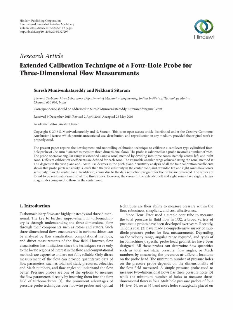
Figure 2 Calibration tunnel calibration device probe and instru-mentation
In such applications using five-hole probe seven-hole probeor probe of higher number of holes is difficult and results inlarge errors due to blockage The present four-hole pressureprobe has relatively high spatial resolution that is center-to-center distance between holes in the pitch plane is 088mmand center-to-center distance in the yaw plane is 195mm
4 Calibration Tunnel Calibration DeviceInstrumentation Calibration Procedureand Calibration Program
The four-hole probe is calibrated in an open-jet low speedcalibration tunnel facility of Thermal Turbomachines Labo-ratory Department of Mechanical Engineering IIT Madraswhich is shown in Figure 2The calibration tunnel consists ofa low pressure centrifugal fan driven by a variable speed DCmotor The high pressure nonuniform turbulent delivery airfrom the centrifugal fan is sent through a settling chamber tothe jet exit through a contraction section of 9 1 contractionratio The flow in the jet of the calibration tunnel is uniform
within plusmn05 of the center line stream velocity and theturbulence level is about 1 The flow in the core region ofthe jet is found to be along its axis without any deviationThe total pressure is measured from the averaged wall staticpressures on the settling chamber wall The static pressureis taken as atmospheric Earlier quantification tests on thecalibration tunnel using a three-hole probe at the nozzle exitverified that the total pressure measured from the averagedwall static pressures on the settling chamber wall is equalto the total pressure within plusmn1 and the static pressure isatmospheric This calibration tunnel is routinely used for thecalibration of single andmultihole pressure probes and singleand multisensor thermal anemometer probes
The probe is mounted in a calibration deviceThe calibra-tion device consists of a base plate a c-clamp and protractorswith pointers for measurement of the pitch (120573) and yaw(120572) angles The twenty-channel single selection scanning box(model number FCO 91-3) and FC012 digital micromanome-ter with a range of 1ndash200mm of water and sensitivity of01mm of differential air pressure manufactured by FurnessControl Ltd Bexhill London were used to measure probepressuresThemicromanometer uses the output signals fromthe selection box to obtain the pressure readings
The four-hole probe is calibrated at a Reynolds numberof 9525 (60ms velocity) based on the probe head diameterA total of 425 (25 times 17 in the yaw and pitch planes resp) ofcalibration points were obtained over a yaw angle range ofplusmn60 degrees and a pitch angle range of 30 to minus50 degreesat an interval of 5 degrees in the yaw and pitch anglerange
5 Results and Discussion
51 Calibration Coefficients and Curves The pressure datarecorded during calibration was used to plot calibration
4 International Journal of Rotating Machinery
curves using the traditional calibration coefficients definedfor one such probe earlier [14]
The traditional normalized calibration coefficients for thefour-hole probe are defined as follows
119862PYAW =1198752minus 1198753
119863
119862PPITCH =1198751minus 1198754
119863
119862PTOTAL =119875119874minus 1198751
119876
=119875119874minus 1198751
119875119874
119862PSTATIC =(1198752+ 1198753) 2 minus 119875
119878
119876
=
(1198752+ 1198753) 2
119875119874
(1)
where119863 = 1198751minus(1198752+1198753)2119862PYAW represents yaw coefficient
119862PPITCH represents pitch coefficient 119862PTOTAL and 119862PSTATICare the total and static pressure coefficients and 119863 is thenormalization factor that is introduced in all the coefficientsThese coefficients become independent of dynamic pressurewhen normalized with the factor 119863 As a result 119862PYAW and119862PPITCH are only a function of flow angles and both totaland static pressure coefficients provide the total and staticpressures of the flow
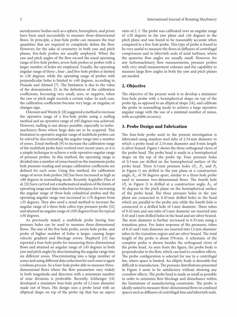
The calibration curve119862PYAW versus119862PPITCH for the probeplotted at an interval of 10 degrees in both the yaw and pitchplanes using the traditional calibration coefficient definitionis shown in Figure 3 From this curve it is clearly evidentthat the probe cannot be used to measure the yaw anglebeyond plusmn30 degrees This limitation in angular range of theprobe using the traditional coefficients is due to the arisingof singular points beyond plusmn30 degrees in yaw angle For atypical cylindrical probe using the above angular coefficientssingular points appear approximately atplusmn37 degrees Singularpoints in the angular coefficients appearwhen the normalizedfactor119863 becomes zero and for the present probe these pointsappear somewhere in between plusmn35 degrees and plusmn40 degreesin yaw angle However the problem of singularity in theangular coefficients is not the real hurdle to increase the angu-lar range of the probeThe real limitation to the angular rangeoccurs when double points appear Double points appearwhen the equations used for angular coefficients producedual solutions [12] Singularities in angular coefficients canbe avoided by discriminating several zones within the wholeangular range and defining a new normalizing factor 119863 ineach zone such that the normalized calibration coefficientsin each zone are independent of both static pressure anddynamic pressure and the normalizing factor 119863 does notbecome zero in their respective zonesThe other way to avoidthis singularity is by using the real dynamic pressure as thenormalizing factor [15] but in such a method an iterativeprocedure is required to arrive at the correct value of dynamicpressure
The calibration coefficients and normalizing factor arecalculated using the pressures measured by the four holesof the probe Hence it is necessary to analyze the pressuredata of each hole of the probe at various flow angles fordiscrimination of zones based on their behavior In this
0 2
0
2
minus2
minus2
120573 = 30∘
120573 = 20∘
120573 = 10∘
120573 = 0∘
120573 = minus10∘
120573 = minus20∘
120573 = minus30∘
120573 = minus40∘
120573 = minus50∘
0
120572 (deg)
Pitc
h co
effici
entC
PPIT
CH
Yaw coefficient CPYAW
minus10
minus20
minus30
minus40
minus50minus60
60
50
40
30
20
10
120572 = 40120572 = minus40
Figure 3 119862PPITCH versus 119862PYAW calibration curve using traditionalcalibration coefficients
section an effort has been made to analyze the pressurecoefficient distributions of the four probe holes over anangular range ofplusmn60 degrees in yaw and+30 tominus50 degrees inpitch Figure 4 shows the distributions of pressure coefficientas a function of yaw angle for three values of pitch angles of0 +30 (maximum value) and minus50 (minimum value) degreesThey are normalized with the measured total pressure (119875
119874)
read during calibration that is 119901119894= (119875119894119875119874) The pressure
coefficient of the respective hole is expected to be maximum(119901119894= 1) when the flow is aligned with the hole axis And it
is expected to be minimum when the flow is perpendicularto the hole axis For a typical cylindrical three-hole probeused in measuring 2D flows these pressure coefficients aremaximum at 0 degrees for center hole and maximum for theleft and right holes at their respective tap angles (constructionangle 120575
1) when the pitch angle is zero The minimum and
maximumpressures for the two side holes 1199012and 119901
3 are also
presented in Figures 4(a)ndash4(c) These are shown by a starredsymbol with L and R used to represent these values for thetwo side holes 119901
2and 119901
3 The minimum pressures for the
bottom hole 1199014 in the negative and positive yaw angles are
presented by B in Figure 4(c)They occur at the yaw angles ofminus35 and 40 degrees and have almost the same magnitude
For the present four-hole probe 119901119894is not maximum for
the holes in the yaw plane (1198751 1198752 and 119875
3) at a pitch angle of 0
degrees (Figure 4(d)) Instead1199011ismaximumat a pitch angle
ofminus10 degrees and at a yaw angle of 0 degrees1199012is maximum
International Journal of Rotating Machinery 5
00
05
10Calibrated boundary
RL
p1
p2
p3
p4
Left zone Center zone Right zone
Actual boundaryExtended boundary
R L
Yaw angle 120572 (deg)
minus10
minus05
minus15
minus30minus60
120573 = 0∘
Non
dim
ensio
nal p
ress
ures
0 30
(a)
Calibrated boundary
60
LR
Extended boundaryActual boundary
L R
Yaw angle 120572 (deg)
00
05
10
minus10
minus05
minus15
Non
dim
ensio
nal p
ress
ures
Left zone Center zone Right zone
minus30minus60 0 30
p1
p2
p3
p4
120573 = minus50∘
(b)
0 30 60
BB R L
Actual boundary
Extended boundary
Calibrated boundary
LR
00
05
10
minus10
minus05
minus15minus30minus60
Non
dim
ensio
nal p
ress
ures
Left zone Center zone Right zone
120573 = 30∘
Yaw angle 120572 (deg)
p1
p2
p3
p4
(c)
0 25
00
05
10
Starred symbol represents
Pitch angle 120573 (deg)
minus05minus50 minus25
Non
dim
ensio
nal p
ress
ures
maximum value
P1PO at 120572 = 30∘
P1PO at 120572 = minus40∘
P2PO at 120572 = minus60∘
P3PO at 120572 = 50∘
P4PO at 120572 = 50∘
P1 at 120572 = 0∘PO
(d)
Figure 4 Pressure distributions of the four-hole probe and zone division
6 International Journal of Rotating Machinery
20 60
30
Pitc
h an
gle
120573(d
eg)
minus20minus60
minus50
minus10
Yaw angle 120572 (deg)
Extended center zoneExtended left zone Extended right zone
Left zone Center zone Right zone Total
Number of calibration points 119 187 119 425Percentage 28 44 28 100
Yaw angle range
Number of points in extended zone 153 221 153
Yaw angle range in extended zone
minus60∘ to minus30∘
minus60∘ to minus20∘
minus25∘ to 25∘
minus30∘ to 30∘
30∘ to 60∘
20∘ to 60∘
Figure 5 Zone division including extended zones
at a pitch angle of minus15 degrees and a yaw angle of minus60 degreesand 119901
3is maximum at a pitch angle of minus10 degrees and a
yaw angle of 50 degrees The shift in the maximum pressurecoefficient from 0 degrees in pitch angle to minus10minus15 degreesin pitch angle is due to the placing of the three holes inyaw plane at the leading edge of the hemispherical shapedhead At each pitch angle the pressure coefficients 119901
2 1199013are
similar to 1199011except that their distributions are shifted by the
construction angle The pressure coefficient of the bottomhole 119901
4 is maximum when the pitch angle is minus40 degrees
(Figure 4(d)) and reduces as the pitch angle becomes positiveAt a pitch angle of +30 degrees the pressure coefficient 119901
4
almost becomes constant over the entire yaw angle range(Figure 4(c))This is one of the reasons why the probe cannotbe used beyond+30 degrees in pitch angle At this pitch anglethe bottom hole is at an angle of 45 degrees with respect tothe flow direction and the flow is prone to separation at thebottom hole tap However the pitch range of the probe inpositive pitch direction can be further increased by reducingthe construction angle 120575
2 Arguelles Dıaz et al [11] had
shown that a construction angle of 25 degrees gave a largeryaw angle range for a three-hole probe Sitaram and Srikanth[16] had experimentally verified that a smaller constructionangle increases the calibration range of a five-hole probe inboth the yaw and the pitch planes
Figure 5 shows the division of the different zones overthe entire calibration range The zones are identified usingthe pressure measured in the holes of the yaw plane (119875
1
1198752 and 119875
3) The division of each zone is based upon the
angular interval where one of the pressures in the holes ofthe yaw plane is maximum As a result there are three zonescenter zone when 119875
1is the highest pressure left zone when
1198752is the highest pressure and right zone when 119875
3is the
highest value As indicated in Figure 4 the center zone hasa boundary of plusmn25 degrees However this is not the realboundary of the center zone it is the calibrated boundaryThis arises as the calibration is carried out over intervals of 5degrees The actual boundary of the zones is identified usingthe criterion of equal pressures from the probe holes in theadjacent zones The boundary between the center and leftzones is identified at the yaw angle where 119901
1= 1199012 The
boundary between the center and right zones is identifiedat the yaw angle where 119901
1= 1199013 The actual boundary of
center zone left zone and right zones always falls in betweenplusmn25 degrees and plusmn30 degrees (see Figures 4(a) 4(b) and4(c)) Sometimes a measured data point may fall in betweenthese two boundaries say 120572 = 275 degrees Although it ispossible to predict to which zone they belong (center zone orright zone depending upon which pressure center or righthole is maximum) local calibration data are not availableIn such cases there are two methods of determining thecalibration coefficients extrapolation or interpolation witha zone extension [11] Extrapolation is not recommendedbecause it may result in larger errors In the present caseinterpolation with a zone extension is used Zone extensionis carried out for each zone to the nearest surrounding data
International Journal of Rotating Machinery 7
Table 1 Definition of calibration coefficients
Zone 119863 119862PYAW 119862PPITCH 119862PSTATIC 119862PTOTAL
Center zone1198751is maximum 119875
1minus (1198752+ 1198753)2 (119875
2minus 1198753)119863 (119875
1minus 1198754)119863 [(119875
2+ 1198753)2 minus 119875
119878]119876 = (119875
2+ 1198753)2119875119874(119875119874minus 1198751)119876 = 1 minus 119875
1119875119874
Left zone1198752is maximum (119875
1+ 1198752)2 minus 119875
3(1198753minus 1198752)119863 (119875
1minus 1198754)119863 (119875
3minus 119875119878)119876 = 119875
3119875119874
(119875119874minus 1198752)119876 = 1 minus 119875
2119875119874
Right zone1198753is maximum (119875
1+ 1198753)2 minus 119875
2(1198753minus 1198752)119863 (119875
1minus 1198754)119863 (119875
2minus 119875119878)119876 = 119875
2119875119874
(119875119874minus 1198753)119876 = 1 minus 119875
3119875119874
point of the adjacent zone As a result the center zone isextended to yaw angles of plusmn35 degrees and the left and rightzones are extended to a yaw angle of minus20 and 20 degreesrespectively
The calibration space is divided into three zones namelycenter (yaw angle range of plusmn30∘) left (yaw angle range ofminus60∘to minus20∘) and right (yaw angle range of 20∘ to 60∘) zoneswith zones overlapping so that no yaw region is left withoutcalibration coefficients Calibration coefficients are definedfor each zone and computed The calibration coefficients foreach zone are defined as shown in Table 1
In Table 1 119876 = 119875119874minus 119875119878= 119875119874(119876 rarr 119875
119874as 119875119878rarr 0)
The calibration curves for the center left and right zonesare shown in Figures 6 and 7 The calibration curves ofthe left zone are almost a mirror image of the calibrationcurves of the right zone Although the calibration was carriedout over intervals of 5 degrees for the sake of clarity thecalibration curves are presented for intervals of 10 degreesCalibration curves of 119862PYAW versus 119862PPITCH are presented asgrids while 119862PTOTAL and 119862PSTATIC are presented as contourswith 119862PYAW and 119862PPITCH on the 119909 and 119910 axes The calibrationcurves of 119862PYAW versus 119862PPITCH for all three zones arerepresented by spline curves passing through each calibrationdata point In the calibration curves of119862PYAW versus119862PPITCHnearly vertical lines are at constant yaw angle 120572 and nearlyhorizontal curves are at constant pitch angle 120573 In an idealcase 119862PYAW versus 119862PPITCH should be a square over theentire calibration range but this cannot be achieved in a realsituation However in the present case each grid seems tobe nearly rectangular except at the extremities of yaw andpitch angles in all the zones At the extremities the grid isdistorted into a diamond shape especially along the diagonaldirections of the center zone
This severe distortion from a rectangular shapemay resultin an error of flow angle determination From the calibrationcurves of 119862PYAW versus 119862PPITCH of the center zone it can beobserved that the probe has a smaller range of119862PPITCH valuescompared to 119862PYAW values This reduced range of 119862PPITCHvalues will result in an increased sensitivity of the probe tosmall variations of flow in the pitch plane The reduction inthe range of 119862PPITCH for the probe is due to employing ofonly two pressure holes in the pitch plane The contours of119862PTOTAL and119862PSTATIC seem to be nearly concentric in all threezones
52 Sensitivity Analysis of the Calibration Coefficients Asensitivity analysis of the calibration coefficients was carried
out for the three zones to quantify the accuracy of themeasurements Sensitivity graphs show the variation of thedependent quantities as a function of the independent quan-tities The dependent quantities here are the four calibrationcoefficients 119862PYAW 119862PPITCH 119862PTOTAL and 119862PSTATIC and theindependent quantities are the yaw angle (120572) and the pitchangle (120573) The sensitivity coefficients are defined as follows
Δ119862P119894 =119862P(119894+1) minus 119862P(119894minus1)
Angle (119894 + 1) minus Angle (119894 minus 1) (2)
where 119862P119894 refers to one of the four calibration coefficientsnamely 119862PYAW 119862PPITCH 119862PSTATIC or 119862PTOTAL and Angle isthe yaw or pitch angle where the calibration data are taken
The sensitivity coefficients for the center left and rightzones are shown in Figures 8 and 9 In the center zone theprobe pressures change rapidly at large yaw and pitch anglesHence the calibration coefficients at large values of yaw andpitch angles have higher sensitivity Higher sensitivity impliesmore accurate measurements It is to be kept in mind thatsmall errors in themeasured pressures result in large errors inthe calibration coefficients and their sensitivity At low valuesof the yaw and pitch angles the sensitivity coefficients are lowThe curves in the center zone are almost symmetric with zerovalue of yaw angle but they are asymmetric with pitch anglethis is due to the asymmetric geometry of the probe holes inthe pitch planeThe calibration coefficients in the center zoneare less sensitive to the change of the pitch angle thanwith theyaw angle a result of having only two holes in the pitch planeinstead of three holes
53 Interpolation Errors A look up table method has beendeveloped for a five-hole probe by Sitaram and Kumar [17]to determine the four unknown quantities namely yaw andpitch angles and static and total pressure coefficients fromthe calculated yaw and pitch coefficients A similar methodis utilized here for determining the flow quantities from thepresent four-hole probe configuration No additional dataare taken for interpolation during the calibration of theprobe However a calibration data interval of 10 degreesrather than 5 degrees is used All the calibration data aredirectly measured data A calibration interval of 10 degreesis relatively large Sumner [18] recommended that this is thelargest calibration interval that can be used with a seven-hole probe The interpolated values are compared with thoseobtained during calibration Histograms of errors in yaw andpitch angles are presented in Figure 10 The errors at the
8 International Journal of Rotating Machinery
0 2
0
2
minus2
minus2
CPSTATIC
Pitc
h co
effici
entC
PPIT
CH
Yaw coefficient CPYAW
0809
01
09
0203
08
04
0507
06
0505
CPTOTAL
0
2
minus2
Pitc
h co
effici
entC
PPIT
CH
Center zone120572 = minus30∘
20∘
10∘
0∘
minus10∘
minus20∘
minus30∘
minus40∘
120573 = minus50∘
minus25∘
minus20∘
minus10∘0∘
10∘20∘
30∘
25∘
30∘
0
2
minus2
Pitc
h co
effici
entC
PPIT
CH
minus01
minus02
minus04minus05
minus06
minus03
minus02
minus03
Figure 6 Calibration curves of the four-hole probe for the centerzone
extremes of the calibration range for each zone are omittedfrom these figures For the sake of brevity histograms ofthe errors in yaw angle and static pressure coefficients arepresented for the central zone and histograms of the errorsin pitch angle and total pressure coefficients are presented forthe right and left zones respectivelyMost of the errors in yawand pitch angles are within plusmn1 degrees and most of the errorsin total and static and pressures are within minus001 to 002 ofthe dynamic head From the figure it can be observed thatthe errors have slightly higher magnitude in the left and rightzones compared to the center zone
The maximum minimum RMS and SD values of errorsin yaw and pitch angles and total static and dynamicpressures are also presented in Table 2
Except for yaw and pitch angles and the static pressurecoefficient in the right zone the errors are very smallThe large values of errors occur near the extreme rangeof the calibration zones The errors are due to the datareduction program only All other measurement errors suchas instrumentation errors errors due to the calibration (zeroangle settings pitch and yaw angle measurements duringcalibration etc) are not included For Table 2 the calibrationdata is given at an interval of 10 degrees The calibration dataat an interval of 5 degrees (excluding the data at 10-degreeinterval) are given as measured data The errors are almostnegligible when both calibration data and measured data aregiven at an interval of 5 degrees The errors presented by Leeand Jun [19] who used a calibration interval of 5 degrees intheir data reduction program have similar magnitude
6 Conclusions
From the present investigation the following major conclu-sions are drawn
(1) The calibration range of a cantilever type four-holeprobe is extended to plusmn60 degrees in the yaw planeand minus50 to +30 degrees in the pitch plane This isachieved by dividing the calibration space into threezones namely center left and right zones The zonesare overlapping so that no point in the calibrationspace is left without calibration coefficients In eachof the zones the calibration coefficients are defineddifferently
(2) The probe pitch sensitivity is lower than the yawsensitivity in the center zone Extended left and rightzones have lower sensitivity than the center zone
(3) Errors due to the data reduction program for theprobe are presented for all the zones and the errorsare found to be reasonably low in all three zonesHowever the errors in the extended left and rightzones have slightly larger magnitudes compared tothose in the center zone
(4) From the present investigation it can be concludedthat the probe can be used for measurement of highlythree-dimensional flows that occur in turbomachin-ery and other aerodynamic flows particularly inconfined measurement spaces
International Journal of Rotating Machinery 9
09
09
08
08
01
07
02
06
03
0504
04 03
030
1
minus1
CPTOTAL
CPP
ITCH
0
1Left zone 120572 = minus20∘
20∘
10∘
0∘
minus10∘
minus20∘
minus30∘
minus40∘
120573 = minus50∘
minus60∘
minus50∘
minus40∘
minus30∘ 30∘
minus1
CPP
ITCH
CPP
ITCH
minus1minus2
minus05
minus13
minus07
minus15
minus11
minus11
minus09 minus07
CPSTATIC
0
1
minus1
CPYAW
09
04
09
08
01
07
02
06
03
05
04
03 02
02
0
1
CPP
ITCH
CPTOTAL
1 2
0
1
CPP
ITCH
minus07
minus07
minus13
minus05
minus11
minus07
minus09
minus11minus09
minus11
CPSTATIC
CPYAW
0
1
Right zone
CPP
ITCH
20∘
10∘
0∘
minus10∘
minus20∘
120573 = minus50∘
minus30∘
minus40∘
30∘
40∘
50∘
30∘
120572 = 60∘
120572 = 20∘
Figure 7 Calibration curves of the four-hole probe for the left and right zones
(5) It is important to emphasize that measurements bymultihole probes are affected by flow Mach andReynolds numbers Hence it is essential that theprobes be calibrated at different Mach and Reynoldsnumbers and methods be developed to account for
these effects on the probe measurements The cali-bration is presented at only one velocity to establishthe extended calibration technique The probe will becalibrated at different Mach and Reynolds numbersandmethodswill be developed to include these effects
10 International Journal of Rotating Machinery
0 20
002 002
006
010
001
001
minus40 minus20minus002
minus002
minus001
CPT
OTA
L
CPS
TATI
C
CPY
AW
Pitch angle 120573C
PPIT
CH
120572 120572
minus10∘
10∘
minus20∘ 20∘minus30∘
30∘
0∘
0 30004
012
020
000
008
002
002
minus30
minus004
minus008
minus002
minus016
CPT
OTA
L
CPS
TATI
C
CPY
AW
Yaw angle 120572
CPP
ITCH
120573 120573
minus30∘
minus20∘
minus10∘
minus40∘
20∘
minus50∘
30∘
0∘
10∘
Figure 8 Sensitivity curves of the calibration coefficients in the center zone
0 20
000
000
005
002
004Left zone
minus40
minus002
minus005
minus004
minus003
minus20
CPT
OTA
L
CPS
TATI
C
Pitch angle 120573 (deg)
CPY
AW
CPP
ITCH
120572120572
minus40∘minus50∘minus60∘
minus20∘minus30∘
20 40 60
004
002
004
003Right zone
minus004
minus004
minus002
minus002
CPT
OTA
L
Yaw angle 120572
CPY
AW
CPS
TATI
CC
PPIT
CH
120573 120573
minus30∘minus20∘
minus10∘minus40∘
20∘minus50∘
30∘0∘10∘
Figure 9 Sensitivity curves of the calibration coefficients in the left and right zones
International Journal of Rotating Machinery 11
24
46
33
15
0
20
40
Center zone
Perc
enta
ge o
f poi
nts
Δ120572
1 24
6
39 40
8
0 10
20
40
Right zone
Error in angle (deg)minus1minus2
Perc
enta
ge o
f poi
nts
Δ120573
3 1 24
11
35
25
13
3 3
Left zoneΔCPTOTAL
5
10
34
1720
85
Error in pressure coefficients000 002
Center zone
minus002
ΔCPSTATIC
Figure 10 Histograms of interpolation errors of the four-hole probe in different zones
Table 2 Errors in yaw and pitch angles and total and static pressure coefficients
Zone Error in yaw angle Δ120572 (deg) Error in total pressure coefficientΔ119862PTOTAL
Max Min RMS SD Max Min RMS SDCenter 100 minus127 036 035 0020 minus0029 0012 0008Left 085 minus127 032 032 0020 minus0029 0008 0008Right 061 minus203 054 054 0022 minus0015 0008 0008
Zone Error in pitch angle Δ120573 (deg) Error in static pressure coefficientΔ119862PSTATIC
Max Min RMS SD Max Min RMS SDCenter 089 minus134 059 038 0028 minus0028 0011 0010Left 089 minus114 033 033 0028 minus0028 0010 0010Right 085 minus211 053 050 0027 minus0039 0015 0014
12 International Journal of Rotating Machinery
on the probe measurements These results will bepresented in a future paper
Nomenclature
Center leftand right
Center left and right zones of calibrationspace (see Figures 4 and 5)
119862PPITCH Pitch coefficient (defined in text)119862PSTATIC Static pressure coefficient (defined in text)119862PTOTAL Total pressure coefficient (defined in text)119862PYAW Yaw coefficient (defined in text)
119863 Probe dynamic pressure Pa (defined intext)
Max MinRMS andSD
Maximum minimum root mean squareand standard deviation values ofinterpolation error
119875119874 Total pressure Pa119875119878 Static pressure Pa1198751 1198752 1198753
and 1198754
Pressures measured by probe holes 1 to 4Pa
1199011 1199012 1199013
and 1199014
Pressures measured by probe holes 1 to 4nondimensionalized with 119875
119874
119876 Dynamic pressure = 119875119874minus 119875119878= 119875119874
(119876 rarr 119875119874as 119875119878rarr 0) Pa
120572 Yaw angle deg120573 Pitch angle degΔ120572 Interpolation error of yaw angle degΔ120573 Interpolation error of pitch angle degΔ119862P Sensitivity of calibration coefficient 119862PΔ119862PSTATIC
Interpolation error of static pressurecoefficient
Δ119862PTOTALInterpolation error of total pressurecoefficient
Competing Interests
The authors declare that there is no conflict of interestsregarding the publication of this paper
References
[1] N Sitaram B Lakshminarayana and A Ravindranath ldquoCon-ventional probes for the relative flow measurement in a turbo-machinery rotor blade passagerdquo ASME Journal of Engineeringfor Power vol 103 no 2 pp 406ndash414 1981
[2] D Telionis Y Yang and O Rediniotis ldquoRecent developmentsin multi-hole probe technologyrdquo in Proceedings of the 20thInternational Congress of Mechanical Engineering (COBEM rsquo09)Gramado Brazil November 2009
[3] T J Dudzinski and L N Krause ldquoFlow-direction measurementwith fixed-position probesrdquo Tech Rep NASA-TM-X-19041969
[4] N Sitaram and A L Treaster ldquoA simplified method of usingfour-hole probes to measure three-dimensional flow fieldsrdquoJournal of Fluids Engineering vol 107 no 1 pp 31ndash35 1985
[5] A L Treaster and A M Yocum ldquoThe calibration and applica-tion of five-hole probesrdquo ISA Transactions vol 18 no 3 pp 23ndash34 1979
[6] R W Gallington ldquoMeasurement of very large flow angles withnon-nulling seven-hole probesrdquo Tech Rep USAFA-TR-80-171980
[7] A J Pisasale and N A Ahmed ldquoA novel method for extendingthe calibration range of five-hole probe for highly three-dimensional flowsrdquo Flow Measurement and Instrumentationvol 13 no 1-2 pp 23ndash30 2002
[8] C Ostowari and W H Wentz Jr ldquoModified calibration tech-nique of a five-hole probe for high flow anglesrdquo Experiments inFluids vol 1 no 3 p 166 1983
[9] N Sitaram and M Govardhan ldquoLarge angle calibration of fivehole probesrdquo Journal of the Aeronautical Society of India vol 54no 3 pp 265ndash272 2002
[10] C Venkateswara Babu M Govardhan and N Sitaram ldquoAmethod of calibration of a seven-hole pressure probe for mea-suring highly three-dimensional flowsrdquo Measurement Scienceand Technology vol 9 no 3 pp 468ndash476 1998
[11] K M Arguelles Dıaz J M Fernandez Oro and E BlancoMarigorta ldquoDirect calibration framework of triple-hole pres-sure probes for incompressible flowrdquoMeasurement Science andTechnology vol 19 no 7 Article ID 075401 2008
[12] K M Arguelles Dıaz J M Fernandez Oro and E BlancoMarigorta ldquoExtended angular range of a three-hole cobrapressure probe for incompressible flowrdquoASME Journal of FluidsEngineering vol 130 no 10 Article ID 101401 pp 1ndash6 2008
[13] I C Shepherd ldquoA four-hole pressure probe for fluid flow mea-surements in three dimensionsrdquo Journal of Fluids Engineeringvol 103 no 4 pp 590ndash594 1981
[14] J P Schlienger Evolution of unsteady secondary flows in a multi-stage shrouded axial turbine ETH no 15230 [PhD dissertation]ETH Zurich Switzerland 2003
[15] D Contini G Manfrida and V Michelassi ldquoSecondary flowmeasurements in a gas turbine cascade by a 3D pneumaticproberdquo in Proceedings of the 14th Symposium on MeasuringTechniques for Transonic and Supersonic Flows in Cascades andTurbomachines Limerick Ireland 1999
[16] N Sitaram and K Srikanth ldquoEffect of chamfer angle on thecalibration curves of five hole probesrdquo International Journal ofRotating Machinery vol 2014 Article ID 704315 11 pages 2014
[17] N Sitaram and S Kumar ldquoLook up table method for fivehole probe data reductionrdquo in Proceedings of the 38th NationalConference on FluidMechanics and Fluid Power Paper no EM08 pages Bhopal India December 2011
[18] D Sumner ldquoA comparison of data-reduction methods for aseven-hole proberdquo Journal of Fluids Engineering vol 124 no 2pp 523ndash527 2002
[19] S W Lee and S B Jun ldquoReynolds number effects on thenon-nulling calibration of a cone-type five-hole probe forturbomachinery applicationsrdquo Journal of Mechanical Scienceand Technology vol 19 no 8 pp 1632ndash1648 2005
International Journal of
AerospaceEngineeringHindawi Publishing Corporationhttpwwwhindawicom Volume 2014
RoboticsJournal of
Hindawi Publishing Corporationhttpwwwhindawicom Volume 2014
Hindawi Publishing Corporationhttpwwwhindawicom Volume 2014
Active and Passive Electronic Components
Control Scienceand Engineering
Journal of
Hindawi Publishing Corporationhttpwwwhindawicom Volume 2014
International Journal of
RotatingMachinery
Hindawi Publishing Corporationhttpwwwhindawicom Volume 2014
Hindawi Publishing Corporation httpwwwhindawicom
Journal ofEngineeringVolume 2014
Submit your manuscripts athttpwwwhindawicom
VLSI Design
Hindawi Publishing Corporationhttpwwwhindawicom Volume 2014
Hindawi Publishing Corporationhttpwwwhindawicom Volume 2014
Shock and Vibration
Hindawi Publishing Corporationhttpwwwhindawicom Volume 2014
Civil EngineeringAdvances in
Acoustics and VibrationAdvances in
Hindawi Publishing Corporationhttpwwwhindawicom Volume 2014
Hindawi Publishing Corporationhttpwwwhindawicom Volume 2014
Electrical and Computer Engineering
Journal of
Advances inOptoElectronics
Hindawi Publishing Corporation httpwwwhindawicom
Volume 2014
The Scientific World JournalHindawi Publishing Corporation httpwwwhindawicom Volume 2014
SensorsJournal of
Hindawi Publishing Corporationhttpwwwhindawicom Volume 2014
Modelling amp Simulation in EngineeringHindawi Publishing Corporation httpwwwhindawicom Volume 2014
Hindawi Publishing Corporationhttpwwwhindawicom Volume 2014
Chemical EngineeringInternational Journal of Antennas and
Propagation
International Journal of
Hindawi Publishing Corporationhttpwwwhindawicom Volume 2014
Hindawi Publishing Corporationhttpwwwhindawicom Volume 2014
Navigation and Observation
International Journal of
Hindawi Publishing Corporationhttpwwwhindawicom Volume 2014
DistributedSensor Networks
International Journal of
2 International Journal of Rotating Machinery
aerodynamic bodies such as a sphere hemisphere and prismhave been used successfully to measure three-dimensionalflows In principle a four-hole probe can measure the fourquantities that are required to completely define the flowHowever for the sake of symmetry in both yaw and pitchplanes five-hole probes are usually employed When theyaw and pitch angles of the flow exceed the usual operatingrange of five-hole probes seven-hole probes or probes with alarger number of holes are employed Usually the operatingangular range of three- four- and five-hole probes is limitedto plusmn30 degrees while the operating range of probes withperpendicular holes is limited to plusmn40 degrees according toPisasale and Ahmed [7] The limitation is due to the valueof the denominator 119863 in the definition of the calibrationcoefficients becoming very small zero or negative whenthe yaw or pitch angle exceeds a certain value In such casethe calibration coefficients become very large or singular orchanges sign
Ostowari andWentz Jr [8] suggested amethod to increasethe operative range of a five-hole probe using a nullingmethod and an operative range of plusmn85 degrees was achievedHowever nulling is not always possible especially in turbo-machinery flows where large data are to be acquired Thislimitation in operative angular range of multihole probes canbe solved by discriminating the angular range into a numberof zones Zonal methods [9] to increase the calibration rangeof the multihole probe have evolved over recent years as it isa simple technique to achieve a wide operative angular rangeof pressure probes In this method the operating range isdivided into a number of zones based on themaximumprobehole pressure reading and unique calibration coefficients aredefined for each zone Using this method the calibrationrange of seven-hole probes [10] has been increased as high asplusmn80 degrees in nonnulling mode Recently Arguelles Dıaz etal [11] have carried out amathematical analysis of the limits ofoperating range and data reduction techniques for increasingthe angular range of three-hole cylindrical probes and theoperating angular range was increased to plusmn70 degrees fromplusmn35 degrees They also used a zonal method to increase theangular range of a three-hole cobra type pressure probe [12]and attained an angular range ofplusmn105 degrees from the typicalplusmn30 degrees
As previously stated a multihole probe having fourpressure holes can be used to measure three-dimensionalflows The size of the five-hole probe seven-hole probe andprobe of higher number of holes is larger causing largervelocity gradient and blockage errors Shepherd [13] hasreported a four-hole probe for measuring three-dimensionalflows and attained an angular range of plusmn45 degrees in bothyaw and pitch angles by discriminating the angular range intosix different zones Discriminating into a large number ofzones andusing different data reduction for each zone is againa tedious process So a four-hole probe able tomeasure three-dimensional flows where the flow parameters vary widelyin both magnitude and direction with a minimum numberof zone divisions is preferable Recently Schlienger [14]developed a miniature four-hole probe of 12mm diametermade out of brass His design uses a probe head with anelliptical shape on top of the probe tip that has an aspect
ratio of 2 1 The probe was calibrated over an angular rangeof plusmn20 degrees in the yaw plane and plusmn16 degrees in thepitch plane and was found to be reasonably accurate whencompared to a five-hole probe This type of probe is found tobe very useful to measure the flows in diffusers of centrifugalcompressors and in labyrinth seals of axial turbines wherethe spanwise flow angles are usually small However forany turbomachinery flow measurements pressure probeswith very small measurement volumes and the capability tomeasure large flow angles in both the yaw and pitch planesare needed
2 Objective
The objective of the present work is to develop a miniaturefour-hole probe with a hemispherical shape on top of theprobe tip as opposed to an elliptical shape [14] and calibratethe probe in nonnulling mode to achieve a large operativeangular range with the use of a minimal number of zoneswith acceptable accuracy
3 Probe Design and Fabrication
The four-hole probe used in the present investigation isfabricated using stainless steel tube of 254mm diameter towhich a probe head of 254mm diameter and 8mm lengthis silver brazed Figure 1 shows the three orthogonal views ofthe probe head The probe head is made in a hemisphericalshape on the top of the probe tip Four pressure holesof 03mm are drilled on the hemispherical surface of theprobe head Three 03mm pressure holes (119875
1 1198752 and 119875
3
in Figure 1) are drilled in the yaw plane at a constructionangle 120575
1 of 50 degrees apart similar to a three-hole probe
used to measure two-dimensional flows The fourth hole(1198754in Figure 1) is drilled at a construction angle 120575
2 of
45 degrees in the pitch plane on the hemispherical surfaceof the probe head The three pressure holes in the yawplane are connected to 045mm drilled holes in the headwhich are parallel to the probe axis while the fourth hole isconnected to a drilled hole of 1mm diameter Three tubesof 045mm and one tube of 1mm diameter are inserted into045 and 1mm drilled holes in the head and are silver brazedThe stem diameter is further increased to 635mm using atransition piece For faster response of the pressures tubesof 045 and 1mm diameter are inserted into 15mm diametertubes in the transition region and are silver brazed The totallength of the probe is about 570mm A schematic of thecomplete probe is shown besides the orthogonal views ofthe probe head As seen from the figure the probe body isperpendicular to the flow which can lead to crossflow effectsThe probe configuration is selected for use in a centrifugalfan where space is limited An elliptic body is desirable butdifficult tomanufactureThe pressure distributions presentedin Figure 4 seem to be satisfactory without showing anycrossflow effects The probe head is made as small as possiblein order to minimize flow blockage and disturbance withinthe limitations of manufacturing constraints The probe isideally suited tomeasure three-dimensional flows in confinedspaces such as diffusers of centrifugal fans and labyrinth seals
International Journal of Rotating Machinery 3
A
B
B
AC C
4 holes dia 03
03
3 holes dia 045
050514
02
088403
644674
8Section A-A
Section B-B
Section C-C
Material stainless steelAll dimensions in mm D
ia 2
3D
ia 2
54
4
Probe headAll dimensions in mm
Probestem
Transitionpiece
Probehead
Pressure take-offtubes
500
208
570
(not to scale)
50 ∘
45 ∘
50∘
Scale 10 1
P1
P4
P3
P2
P1P4
P3
P2
+++
++
R12
7R115
R05
R127
R08
Four-hole probe head (254mm 01998400998400 Dia)
Figure 1 Orthogonal views of the four-hole pressure probe head and schematic of the probe
Figure 2 Calibration tunnel calibration device probe and instru-mentation
In such applications using five-hole probe seven-hole probeor probe of higher number of holes is difficult and results inlarge errors due to blockage The present four-hole pressureprobe has relatively high spatial resolution that is center-to-center distance between holes in the pitch plane is 088mmand center-to-center distance in the yaw plane is 195mm
4 Calibration Tunnel Calibration DeviceInstrumentation Calibration Procedureand Calibration Program
The four-hole probe is calibrated in an open-jet low speedcalibration tunnel facility of Thermal Turbomachines Labo-ratory Department of Mechanical Engineering IIT Madraswhich is shown in Figure 2The calibration tunnel consists ofa low pressure centrifugal fan driven by a variable speed DCmotor The high pressure nonuniform turbulent delivery airfrom the centrifugal fan is sent through a settling chamber tothe jet exit through a contraction section of 9 1 contractionratio The flow in the jet of the calibration tunnel is uniform
within plusmn05 of the center line stream velocity and theturbulence level is about 1 The flow in the core region ofthe jet is found to be along its axis without any deviationThe total pressure is measured from the averaged wall staticpressures on the settling chamber wall The static pressureis taken as atmospheric Earlier quantification tests on thecalibration tunnel using a three-hole probe at the nozzle exitverified that the total pressure measured from the averagedwall static pressures on the settling chamber wall is equalto the total pressure within plusmn1 and the static pressure isatmospheric This calibration tunnel is routinely used for thecalibration of single andmultihole pressure probes and singleand multisensor thermal anemometer probes
The probe is mounted in a calibration deviceThe calibra-tion device consists of a base plate a c-clamp and protractorswith pointers for measurement of the pitch (120573) and yaw(120572) angles The twenty-channel single selection scanning box(model number FCO 91-3) and FC012 digital micromanome-ter with a range of 1ndash200mm of water and sensitivity of01mm of differential air pressure manufactured by FurnessControl Ltd Bexhill London were used to measure probepressuresThemicromanometer uses the output signals fromthe selection box to obtain the pressure readings
The four-hole probe is calibrated at a Reynolds numberof 9525 (60ms velocity) based on the probe head diameterA total of 425 (25 times 17 in the yaw and pitch planes resp) ofcalibration points were obtained over a yaw angle range ofplusmn60 degrees and a pitch angle range of 30 to minus50 degreesat an interval of 5 degrees in the yaw and pitch anglerange
5 Results and Discussion
51 Calibration Coefficients and Curves The pressure datarecorded during calibration was used to plot calibration
4 International Journal of Rotating Machinery
curves using the traditional calibration coefficients definedfor one such probe earlier [14]
The traditional normalized calibration coefficients for thefour-hole probe are defined as follows
119862PYAW =1198752minus 1198753
119863
119862PPITCH =1198751minus 1198754
119863
119862PTOTAL =119875119874minus 1198751
119876
=119875119874minus 1198751
119875119874
119862PSTATIC =(1198752+ 1198753) 2 minus 119875
119878
119876
=
(1198752+ 1198753) 2
119875119874
(1)
where119863 = 1198751minus(1198752+1198753)2119862PYAW represents yaw coefficient
119862PPITCH represents pitch coefficient 119862PTOTAL and 119862PSTATICare the total and static pressure coefficients and 119863 is thenormalization factor that is introduced in all the coefficientsThese coefficients become independent of dynamic pressurewhen normalized with the factor 119863 As a result 119862PYAW and119862PPITCH are only a function of flow angles and both totaland static pressure coefficients provide the total and staticpressures of the flow
The calibration curve119862PYAW versus119862PPITCH for the probeplotted at an interval of 10 degrees in both the yaw and pitchplanes using the traditional calibration coefficient definitionis shown in Figure 3 From this curve it is clearly evidentthat the probe cannot be used to measure the yaw anglebeyond plusmn30 degrees This limitation in angular range of theprobe using the traditional coefficients is due to the arisingof singular points beyond plusmn30 degrees in yaw angle For atypical cylindrical probe using the above angular coefficientssingular points appear approximately atplusmn37 degrees Singularpoints in the angular coefficients appearwhen the normalizedfactor119863 becomes zero and for the present probe these pointsappear somewhere in between plusmn35 degrees and plusmn40 degreesin yaw angle However the problem of singularity in theangular coefficients is not the real hurdle to increase the angu-lar range of the probeThe real limitation to the angular rangeoccurs when double points appear Double points appearwhen the equations used for angular coefficients producedual solutions [12] Singularities in angular coefficients canbe avoided by discriminating several zones within the wholeangular range and defining a new normalizing factor 119863 ineach zone such that the normalized calibration coefficientsin each zone are independent of both static pressure anddynamic pressure and the normalizing factor 119863 does notbecome zero in their respective zonesThe other way to avoidthis singularity is by using the real dynamic pressure as thenormalizing factor [15] but in such a method an iterativeprocedure is required to arrive at the correct value of dynamicpressure
The calibration coefficients and normalizing factor arecalculated using the pressures measured by the four holesof the probe Hence it is necessary to analyze the pressuredata of each hole of the probe at various flow angles fordiscrimination of zones based on their behavior In this
0 2
0
2
minus2
minus2
120573 = 30∘
120573 = 20∘
120573 = 10∘
120573 = 0∘
120573 = minus10∘
120573 = minus20∘
120573 = minus30∘
120573 = minus40∘
120573 = minus50∘
0
120572 (deg)
Pitc
h co
effici
entC
PPIT
CH
Yaw coefficient CPYAW
minus10
minus20
minus30
minus40
minus50minus60
60
50
40
30
20
10
120572 = 40120572 = minus40
Figure 3 119862PPITCH versus 119862PYAW calibration curve using traditionalcalibration coefficients
section an effort has been made to analyze the pressurecoefficient distributions of the four probe holes over anangular range ofplusmn60 degrees in yaw and+30 tominus50 degrees inpitch Figure 4 shows the distributions of pressure coefficientas a function of yaw angle for three values of pitch angles of0 +30 (maximum value) and minus50 (minimum value) degreesThey are normalized with the measured total pressure (119875
119874)
read during calibration that is 119901119894= (119875119894119875119874) The pressure
coefficient of the respective hole is expected to be maximum(119901119894= 1) when the flow is aligned with the hole axis And it
is expected to be minimum when the flow is perpendicularto the hole axis For a typical cylindrical three-hole probeused in measuring 2D flows these pressure coefficients aremaximum at 0 degrees for center hole and maximum for theleft and right holes at their respective tap angles (constructionangle 120575
1) when the pitch angle is zero The minimum and
maximumpressures for the two side holes 1199012and 119901
3 are also
presented in Figures 4(a)ndash4(c) These are shown by a starredsymbol with L and R used to represent these values for thetwo side holes 119901
2and 119901
3 The minimum pressures for the
bottom hole 1199014 in the negative and positive yaw angles are
presented by B in Figure 4(c)They occur at the yaw angles ofminus35 and 40 degrees and have almost the same magnitude
For the present four-hole probe 119901119894is not maximum for
the holes in the yaw plane (1198751 1198752 and 119875
3) at a pitch angle of 0
degrees (Figure 4(d)) Instead1199011ismaximumat a pitch angle
ofminus10 degrees and at a yaw angle of 0 degrees1199012is maximum
International Journal of Rotating Machinery 5
00
05
10Calibrated boundary
RL
p1
p2
p3
p4
Left zone Center zone Right zone
Actual boundaryExtended boundary
R L
Yaw angle 120572 (deg)
minus10
minus05
minus15
minus30minus60
120573 = 0∘
Non
dim
ensio
nal p
ress
ures
0 30
(a)
Calibrated boundary
60
LR
Extended boundaryActual boundary
L R
Yaw angle 120572 (deg)
00
05
10
minus10
minus05
minus15
Non
dim
ensio
nal p
ress
ures
Left zone Center zone Right zone
minus30minus60 0 30
p1
p2
p3
p4
120573 = minus50∘
(b)
0 30 60
BB R L
Actual boundary
Extended boundary
Calibrated boundary
LR
00
05
10
minus10
minus05
minus15minus30minus60
Non
dim
ensio
nal p
ress
ures
Left zone Center zone Right zone
120573 = 30∘
Yaw angle 120572 (deg)
p1
p2
p3
p4
(c)
0 25
00
05
10
Starred symbol represents
Pitch angle 120573 (deg)
minus05minus50 minus25
Non
dim
ensio
nal p
ress
ures
maximum value
P1PO at 120572 = 30∘
P1PO at 120572 = minus40∘
P2PO at 120572 = minus60∘
P3PO at 120572 = 50∘
P4PO at 120572 = 50∘
P1 at 120572 = 0∘PO
(d)
Figure 4 Pressure distributions of the four-hole probe and zone division
6 International Journal of Rotating Machinery
20 60
30
Pitc
h an
gle
120573(d
eg)
minus20minus60
minus50
minus10
Yaw angle 120572 (deg)
Extended center zoneExtended left zone Extended right zone
Left zone Center zone Right zone Total
Number of calibration points 119 187 119 425Percentage 28 44 28 100
Yaw angle range
Number of points in extended zone 153 221 153
Yaw angle range in extended zone
minus60∘ to minus30∘
minus60∘ to minus20∘
minus25∘ to 25∘
minus30∘ to 30∘
30∘ to 60∘
20∘ to 60∘
Figure 5 Zone division including extended zones
at a pitch angle of minus15 degrees and a yaw angle of minus60 degreesand 119901
3is maximum at a pitch angle of minus10 degrees and a
yaw angle of 50 degrees The shift in the maximum pressurecoefficient from 0 degrees in pitch angle to minus10minus15 degreesin pitch angle is due to the placing of the three holes inyaw plane at the leading edge of the hemispherical shapedhead At each pitch angle the pressure coefficients 119901
2 1199013are
similar to 1199011except that their distributions are shifted by the
construction angle The pressure coefficient of the bottomhole 119901
4 is maximum when the pitch angle is minus40 degrees
(Figure 4(d)) and reduces as the pitch angle becomes positiveAt a pitch angle of +30 degrees the pressure coefficient 119901
4
almost becomes constant over the entire yaw angle range(Figure 4(c))This is one of the reasons why the probe cannotbe used beyond+30 degrees in pitch angle At this pitch anglethe bottom hole is at an angle of 45 degrees with respect tothe flow direction and the flow is prone to separation at thebottom hole tap However the pitch range of the probe inpositive pitch direction can be further increased by reducingthe construction angle 120575
2 Arguelles Dıaz et al [11] had
shown that a construction angle of 25 degrees gave a largeryaw angle range for a three-hole probe Sitaram and Srikanth[16] had experimentally verified that a smaller constructionangle increases the calibration range of a five-hole probe inboth the yaw and the pitch planes
Figure 5 shows the division of the different zones overthe entire calibration range The zones are identified usingthe pressure measured in the holes of the yaw plane (119875
1
1198752 and 119875
3) The division of each zone is based upon the
angular interval where one of the pressures in the holes ofthe yaw plane is maximum As a result there are three zonescenter zone when 119875
1is the highest pressure left zone when
1198752is the highest pressure and right zone when 119875
3is the
highest value As indicated in Figure 4 the center zone hasa boundary of plusmn25 degrees However this is not the realboundary of the center zone it is the calibrated boundaryThis arises as the calibration is carried out over intervals of 5degrees The actual boundary of the zones is identified usingthe criterion of equal pressures from the probe holes in theadjacent zones The boundary between the center and leftzones is identified at the yaw angle where 119901
1= 1199012 The
boundary between the center and right zones is identifiedat the yaw angle where 119901
1= 1199013 The actual boundary of
center zone left zone and right zones always falls in betweenplusmn25 degrees and plusmn30 degrees (see Figures 4(a) 4(b) and4(c)) Sometimes a measured data point may fall in betweenthese two boundaries say 120572 = 275 degrees Although it ispossible to predict to which zone they belong (center zone orright zone depending upon which pressure center or righthole is maximum) local calibration data are not availableIn such cases there are two methods of determining thecalibration coefficients extrapolation or interpolation witha zone extension [11] Extrapolation is not recommendedbecause it may result in larger errors In the present caseinterpolation with a zone extension is used Zone extensionis carried out for each zone to the nearest surrounding data
International Journal of Rotating Machinery 7
Table 1 Definition of calibration coefficients
Zone 119863 119862PYAW 119862PPITCH 119862PSTATIC 119862PTOTAL
Center zone1198751is maximum 119875
1minus (1198752+ 1198753)2 (119875
2minus 1198753)119863 (119875
1minus 1198754)119863 [(119875
2+ 1198753)2 minus 119875
119878]119876 = (119875
2+ 1198753)2119875119874(119875119874minus 1198751)119876 = 1 minus 119875
1119875119874
Left zone1198752is maximum (119875
1+ 1198752)2 minus 119875
3(1198753minus 1198752)119863 (119875
1minus 1198754)119863 (119875
3minus 119875119878)119876 = 119875
3119875119874
(119875119874minus 1198752)119876 = 1 minus 119875
2119875119874
Right zone1198753is maximum (119875
1+ 1198753)2 minus 119875
2(1198753minus 1198752)119863 (119875
1minus 1198754)119863 (119875
2minus 119875119878)119876 = 119875
2119875119874
(119875119874minus 1198753)119876 = 1 minus 119875
3119875119874
point of the adjacent zone As a result the center zone isextended to yaw angles of plusmn35 degrees and the left and rightzones are extended to a yaw angle of minus20 and 20 degreesrespectively
The calibration space is divided into three zones namelycenter (yaw angle range of plusmn30∘) left (yaw angle range ofminus60∘to minus20∘) and right (yaw angle range of 20∘ to 60∘) zoneswith zones overlapping so that no yaw region is left withoutcalibration coefficients Calibration coefficients are definedfor each zone and computed The calibration coefficients foreach zone are defined as shown in Table 1
In Table 1 119876 = 119875119874minus 119875119878= 119875119874(119876 rarr 119875
119874as 119875119878rarr 0)
The calibration curves for the center left and right zonesare shown in Figures 6 and 7 The calibration curves ofthe left zone are almost a mirror image of the calibrationcurves of the right zone Although the calibration was carriedout over intervals of 5 degrees for the sake of clarity thecalibration curves are presented for intervals of 10 degreesCalibration curves of 119862PYAW versus 119862PPITCH are presented asgrids while 119862PTOTAL and 119862PSTATIC are presented as contourswith 119862PYAW and 119862PPITCH on the 119909 and 119910 axes The calibrationcurves of 119862PYAW versus 119862PPITCH for all three zones arerepresented by spline curves passing through each calibrationdata point In the calibration curves of119862PYAW versus119862PPITCHnearly vertical lines are at constant yaw angle 120572 and nearlyhorizontal curves are at constant pitch angle 120573 In an idealcase 119862PYAW versus 119862PPITCH should be a square over theentire calibration range but this cannot be achieved in a realsituation However in the present case each grid seems tobe nearly rectangular except at the extremities of yaw andpitch angles in all the zones At the extremities the grid isdistorted into a diamond shape especially along the diagonaldirections of the center zone
This severe distortion from a rectangular shapemay resultin an error of flow angle determination From the calibrationcurves of 119862PYAW versus 119862PPITCH of the center zone it can beobserved that the probe has a smaller range of119862PPITCH valuescompared to 119862PYAW values This reduced range of 119862PPITCHvalues will result in an increased sensitivity of the probe tosmall variations of flow in the pitch plane The reduction inthe range of 119862PPITCH for the probe is due to employing ofonly two pressure holes in the pitch plane The contours of119862PTOTAL and119862PSTATIC seem to be nearly concentric in all threezones
52 Sensitivity Analysis of the Calibration Coefficients Asensitivity analysis of the calibration coefficients was carried
out for the three zones to quantify the accuracy of themeasurements Sensitivity graphs show the variation of thedependent quantities as a function of the independent quan-tities The dependent quantities here are the four calibrationcoefficients 119862PYAW 119862PPITCH 119862PTOTAL and 119862PSTATIC and theindependent quantities are the yaw angle (120572) and the pitchangle (120573) The sensitivity coefficients are defined as follows
Δ119862P119894 =119862P(119894+1) minus 119862P(119894minus1)
Angle (119894 + 1) minus Angle (119894 minus 1) (2)
where 119862P119894 refers to one of the four calibration coefficientsnamely 119862PYAW 119862PPITCH 119862PSTATIC or 119862PTOTAL and Angle isthe yaw or pitch angle where the calibration data are taken
The sensitivity coefficients for the center left and rightzones are shown in Figures 8 and 9 In the center zone theprobe pressures change rapidly at large yaw and pitch anglesHence the calibration coefficients at large values of yaw andpitch angles have higher sensitivity Higher sensitivity impliesmore accurate measurements It is to be kept in mind thatsmall errors in themeasured pressures result in large errors inthe calibration coefficients and their sensitivity At low valuesof the yaw and pitch angles the sensitivity coefficients are lowThe curves in the center zone are almost symmetric with zerovalue of yaw angle but they are asymmetric with pitch anglethis is due to the asymmetric geometry of the probe holes inthe pitch planeThe calibration coefficients in the center zoneare less sensitive to the change of the pitch angle thanwith theyaw angle a result of having only two holes in the pitch planeinstead of three holes
53 Interpolation Errors A look up table method has beendeveloped for a five-hole probe by Sitaram and Kumar [17]to determine the four unknown quantities namely yaw andpitch angles and static and total pressure coefficients fromthe calculated yaw and pitch coefficients A similar methodis utilized here for determining the flow quantities from thepresent four-hole probe configuration No additional dataare taken for interpolation during the calibration of theprobe However a calibration data interval of 10 degreesrather than 5 degrees is used All the calibration data aredirectly measured data A calibration interval of 10 degreesis relatively large Sumner [18] recommended that this is thelargest calibration interval that can be used with a seven-hole probe The interpolated values are compared with thoseobtained during calibration Histograms of errors in yaw andpitch angles are presented in Figure 10 The errors at the
8 International Journal of Rotating Machinery
0 2
0
2
minus2
minus2
CPSTATIC
Pitc
h co
effici
entC
PPIT
CH
Yaw coefficient CPYAW
0809
01
09
0203
08
04
0507
06
0505
CPTOTAL
0
2
minus2
Pitc
h co
effici
entC
PPIT
CH
Center zone120572 = minus30∘
20∘
10∘
0∘
minus10∘
minus20∘
minus30∘
minus40∘
120573 = minus50∘
minus25∘
minus20∘
minus10∘0∘
10∘20∘
30∘
25∘
30∘
0
2
minus2
Pitc
h co
effici
entC
PPIT
CH
minus01
minus02
minus04minus05
minus06
minus03
minus02
minus03
Figure 6 Calibration curves of the four-hole probe for the centerzone
extremes of the calibration range for each zone are omittedfrom these figures For the sake of brevity histograms ofthe errors in yaw angle and static pressure coefficients arepresented for the central zone and histograms of the errorsin pitch angle and total pressure coefficients are presented forthe right and left zones respectivelyMost of the errors in yawand pitch angles are within plusmn1 degrees and most of the errorsin total and static and pressures are within minus001 to 002 ofthe dynamic head From the figure it can be observed thatthe errors have slightly higher magnitude in the left and rightzones compared to the center zone
The maximum minimum RMS and SD values of errorsin yaw and pitch angles and total static and dynamicpressures are also presented in Table 2
Except for yaw and pitch angles and the static pressurecoefficient in the right zone the errors are very smallThe large values of errors occur near the extreme rangeof the calibration zones The errors are due to the datareduction program only All other measurement errors suchas instrumentation errors errors due to the calibration (zeroangle settings pitch and yaw angle measurements duringcalibration etc) are not included For Table 2 the calibrationdata is given at an interval of 10 degrees The calibration dataat an interval of 5 degrees (excluding the data at 10-degreeinterval) are given as measured data The errors are almostnegligible when both calibration data and measured data aregiven at an interval of 5 degrees The errors presented by Leeand Jun [19] who used a calibration interval of 5 degrees intheir data reduction program have similar magnitude
6 Conclusions
From the present investigation the following major conclu-sions are drawn
(1) The calibration range of a cantilever type four-holeprobe is extended to plusmn60 degrees in the yaw planeand minus50 to +30 degrees in the pitch plane This isachieved by dividing the calibration space into threezones namely center left and right zones The zonesare overlapping so that no point in the calibrationspace is left without calibration coefficients In eachof the zones the calibration coefficients are defineddifferently
(2) The probe pitch sensitivity is lower than the yawsensitivity in the center zone Extended left and rightzones have lower sensitivity than the center zone
(3) Errors due to the data reduction program for theprobe are presented for all the zones and the errorsare found to be reasonably low in all three zonesHowever the errors in the extended left and rightzones have slightly larger magnitudes compared tothose in the center zone
(4) From the present investigation it can be concludedthat the probe can be used for measurement of highlythree-dimensional flows that occur in turbomachin-ery and other aerodynamic flows particularly inconfined measurement spaces
International Journal of Rotating Machinery 9
09
09
08
08
01
07
02
06
03
0504
04 03
030
1
minus1
CPTOTAL
CPP
ITCH
0
1Left zone 120572 = minus20∘
20∘
10∘
0∘
minus10∘
minus20∘
minus30∘
minus40∘
120573 = minus50∘
minus60∘
minus50∘
minus40∘
minus30∘ 30∘
minus1
CPP
ITCH
CPP
ITCH
minus1minus2
minus05
minus13
minus07
minus15
minus11
minus11
minus09 minus07
CPSTATIC
0
1
minus1
CPYAW
09
04
09
08
01
07
02
06
03
05
04
03 02
02
0
1
CPP
ITCH
CPTOTAL
1 2
0
1
CPP
ITCH
minus07
minus07
minus13
minus05
minus11
minus07
minus09
minus11minus09
minus11
CPSTATIC
CPYAW
0
1
Right zone
CPP
ITCH
20∘
10∘
0∘
minus10∘
minus20∘
120573 = minus50∘
minus30∘
minus40∘
30∘
40∘
50∘
30∘
120572 = 60∘
120572 = 20∘
Figure 7 Calibration curves of the four-hole probe for the left and right zones
(5) It is important to emphasize that measurements bymultihole probes are affected by flow Mach andReynolds numbers Hence it is essential that theprobes be calibrated at different Mach and Reynoldsnumbers and methods be developed to account for
these effects on the probe measurements The cali-bration is presented at only one velocity to establishthe extended calibration technique The probe will becalibrated at different Mach and Reynolds numbersandmethodswill be developed to include these effects
10 International Journal of Rotating Machinery
0 20
002 002
006
010
001
001
minus40 minus20minus002
minus002
minus001
CPT
OTA
L
CPS
TATI
C
CPY
AW
Pitch angle 120573C
PPIT
CH
120572 120572
minus10∘
10∘
minus20∘ 20∘minus30∘
30∘
0∘
0 30004
012
020
000
008
002
002
minus30
minus004
minus008
minus002
minus016
CPT
OTA
L
CPS
TATI
C
CPY
AW
Yaw angle 120572
CPP
ITCH
120573 120573
minus30∘
minus20∘
minus10∘
minus40∘
20∘
minus50∘
30∘
0∘
10∘
Figure 8 Sensitivity curves of the calibration coefficients in the center zone
0 20
000
000
005
002
004Left zone
minus40
minus002
minus005
minus004
minus003
minus20
CPT
OTA
L
CPS
TATI
C
Pitch angle 120573 (deg)
CPY
AW
CPP
ITCH
120572120572
minus40∘minus50∘minus60∘
minus20∘minus30∘
20 40 60
004
002
004
003Right zone
minus004
minus004
minus002
minus002
CPT
OTA
L
Yaw angle 120572
CPY
AW
CPS
TATI
CC
PPIT
CH
120573 120573
minus30∘minus20∘
minus10∘minus40∘
20∘minus50∘
30∘0∘10∘
Figure 9 Sensitivity curves of the calibration coefficients in the left and right zones
International Journal of Rotating Machinery 11
24
46
33
15
0
20
40
Center zone
Perc
enta
ge o
f poi
nts
Δ120572
1 24
6
39 40
8
0 10
20
40
Right zone
Error in angle (deg)minus1minus2
Perc
enta
ge o
f poi
nts
Δ120573
3 1 24
11
35
25
13
3 3
Left zoneΔCPTOTAL
5
10
34
1720
85
Error in pressure coefficients000 002
Center zone
minus002
ΔCPSTATIC
Figure 10 Histograms of interpolation errors of the four-hole probe in different zones
Table 2 Errors in yaw and pitch angles and total and static pressure coefficients
Zone Error in yaw angle Δ120572 (deg) Error in total pressure coefficientΔ119862PTOTAL
Max Min RMS SD Max Min RMS SDCenter 100 minus127 036 035 0020 minus0029 0012 0008Left 085 minus127 032 032 0020 minus0029 0008 0008Right 061 minus203 054 054 0022 minus0015 0008 0008
Zone Error in pitch angle Δ120573 (deg) Error in static pressure coefficientΔ119862PSTATIC
Max Min RMS SD Max Min RMS SDCenter 089 minus134 059 038 0028 minus0028 0011 0010Left 089 minus114 033 033 0028 minus0028 0010 0010Right 085 minus211 053 050 0027 minus0039 0015 0014
12 International Journal of Rotating Machinery
on the probe measurements These results will bepresented in a future paper
Nomenclature
Center leftand right
Center left and right zones of calibrationspace (see Figures 4 and 5)
119862PPITCH Pitch coefficient (defined in text)119862PSTATIC Static pressure coefficient (defined in text)119862PTOTAL Total pressure coefficient (defined in text)119862PYAW Yaw coefficient (defined in text)
119863 Probe dynamic pressure Pa (defined intext)
Max MinRMS andSD
Maximum minimum root mean squareand standard deviation values ofinterpolation error
119875119874 Total pressure Pa119875119878 Static pressure Pa1198751 1198752 1198753
and 1198754
Pressures measured by probe holes 1 to 4Pa
1199011 1199012 1199013
and 1199014
Pressures measured by probe holes 1 to 4nondimensionalized with 119875
119874
119876 Dynamic pressure = 119875119874minus 119875119878= 119875119874
(119876 rarr 119875119874as 119875119878rarr 0) Pa
120572 Yaw angle deg120573 Pitch angle degΔ120572 Interpolation error of yaw angle degΔ120573 Interpolation error of pitch angle degΔ119862P Sensitivity of calibration coefficient 119862PΔ119862PSTATIC
Interpolation error of static pressurecoefficient
Δ119862PTOTALInterpolation error of total pressurecoefficient
Competing Interests
The authors declare that there is no conflict of interestsregarding the publication of this paper
References
[1] N Sitaram B Lakshminarayana and A Ravindranath ldquoCon-ventional probes for the relative flow measurement in a turbo-machinery rotor blade passagerdquo ASME Journal of Engineeringfor Power vol 103 no 2 pp 406ndash414 1981
[2] D Telionis Y Yang and O Rediniotis ldquoRecent developmentsin multi-hole probe technologyrdquo in Proceedings of the 20thInternational Congress of Mechanical Engineering (COBEM rsquo09)Gramado Brazil November 2009
[3] T J Dudzinski and L N Krause ldquoFlow-direction measurementwith fixed-position probesrdquo Tech Rep NASA-TM-X-19041969
[4] N Sitaram and A L Treaster ldquoA simplified method of usingfour-hole probes to measure three-dimensional flow fieldsrdquoJournal of Fluids Engineering vol 107 no 1 pp 31ndash35 1985
[5] A L Treaster and A M Yocum ldquoThe calibration and applica-tion of five-hole probesrdquo ISA Transactions vol 18 no 3 pp 23ndash34 1979
[6] R W Gallington ldquoMeasurement of very large flow angles withnon-nulling seven-hole probesrdquo Tech Rep USAFA-TR-80-171980
[7] A J Pisasale and N A Ahmed ldquoA novel method for extendingthe calibration range of five-hole probe for highly three-dimensional flowsrdquo Flow Measurement and Instrumentationvol 13 no 1-2 pp 23ndash30 2002
[8] C Ostowari and W H Wentz Jr ldquoModified calibration tech-nique of a five-hole probe for high flow anglesrdquo Experiments inFluids vol 1 no 3 p 166 1983
[9] N Sitaram and M Govardhan ldquoLarge angle calibration of fivehole probesrdquo Journal of the Aeronautical Society of India vol 54no 3 pp 265ndash272 2002
[10] C Venkateswara Babu M Govardhan and N Sitaram ldquoAmethod of calibration of a seven-hole pressure probe for mea-suring highly three-dimensional flowsrdquo Measurement Scienceand Technology vol 9 no 3 pp 468ndash476 1998
[11] K M Arguelles Dıaz J M Fernandez Oro and E BlancoMarigorta ldquoDirect calibration framework of triple-hole pres-sure probes for incompressible flowrdquoMeasurement Science andTechnology vol 19 no 7 Article ID 075401 2008
[12] K M Arguelles Dıaz J M Fernandez Oro and E BlancoMarigorta ldquoExtended angular range of a three-hole cobrapressure probe for incompressible flowrdquoASME Journal of FluidsEngineering vol 130 no 10 Article ID 101401 pp 1ndash6 2008
[13] I C Shepherd ldquoA four-hole pressure probe for fluid flow mea-surements in three dimensionsrdquo Journal of Fluids Engineeringvol 103 no 4 pp 590ndash594 1981
[14] J P Schlienger Evolution of unsteady secondary flows in a multi-stage shrouded axial turbine ETH no 15230 [PhD dissertation]ETH Zurich Switzerland 2003
[15] D Contini G Manfrida and V Michelassi ldquoSecondary flowmeasurements in a gas turbine cascade by a 3D pneumaticproberdquo in Proceedings of the 14th Symposium on MeasuringTechniques for Transonic and Supersonic Flows in Cascades andTurbomachines Limerick Ireland 1999
[16] N Sitaram and K Srikanth ldquoEffect of chamfer angle on thecalibration curves of five hole probesrdquo International Journal ofRotating Machinery vol 2014 Article ID 704315 11 pages 2014
[17] N Sitaram and S Kumar ldquoLook up table method for fivehole probe data reductionrdquo in Proceedings of the 38th NationalConference on FluidMechanics and Fluid Power Paper no EM08 pages Bhopal India December 2011
[18] D Sumner ldquoA comparison of data-reduction methods for aseven-hole proberdquo Journal of Fluids Engineering vol 124 no 2pp 523ndash527 2002
[19] S W Lee and S B Jun ldquoReynolds number effects on thenon-nulling calibration of a cone-type five-hole probe forturbomachinery applicationsrdquo Journal of Mechanical Scienceand Technology vol 19 no 8 pp 1632ndash1648 2005
International Journal of
AerospaceEngineeringHindawi Publishing Corporationhttpwwwhindawicom Volume 2014
RoboticsJournal of
Hindawi Publishing Corporationhttpwwwhindawicom Volume 2014
Hindawi Publishing Corporationhttpwwwhindawicom Volume 2014
Active and Passive Electronic Components
Control Scienceand Engineering
Journal of
Hindawi Publishing Corporationhttpwwwhindawicom Volume 2014
International Journal of
RotatingMachinery
Hindawi Publishing Corporationhttpwwwhindawicom Volume 2014
Hindawi Publishing Corporation httpwwwhindawicom
Journal ofEngineeringVolume 2014
Submit your manuscripts athttpwwwhindawicom
VLSI Design
Hindawi Publishing Corporationhttpwwwhindawicom Volume 2014
Hindawi Publishing Corporationhttpwwwhindawicom Volume 2014
Shock and Vibration
Hindawi Publishing Corporationhttpwwwhindawicom Volume 2014
Civil EngineeringAdvances in
Acoustics and VibrationAdvances in
Hindawi Publishing Corporationhttpwwwhindawicom Volume 2014
Hindawi Publishing Corporationhttpwwwhindawicom Volume 2014
Electrical and Computer Engineering
Journal of
Advances inOptoElectronics
Hindawi Publishing Corporation httpwwwhindawicom
Volume 2014
The Scientific World JournalHindawi Publishing Corporation httpwwwhindawicom Volume 2014
SensorsJournal of
Hindawi Publishing Corporationhttpwwwhindawicom Volume 2014
Modelling amp Simulation in EngineeringHindawi Publishing Corporation httpwwwhindawicom Volume 2014
Hindawi Publishing Corporationhttpwwwhindawicom Volume 2014
Chemical EngineeringInternational Journal of Antennas and
Propagation
International Journal of
Hindawi Publishing Corporationhttpwwwhindawicom Volume 2014
Hindawi Publishing Corporationhttpwwwhindawicom Volume 2014
Navigation and Observation
International Journal of
Hindawi Publishing Corporationhttpwwwhindawicom Volume 2014
DistributedSensor Networks
International Journal of
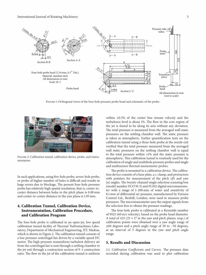
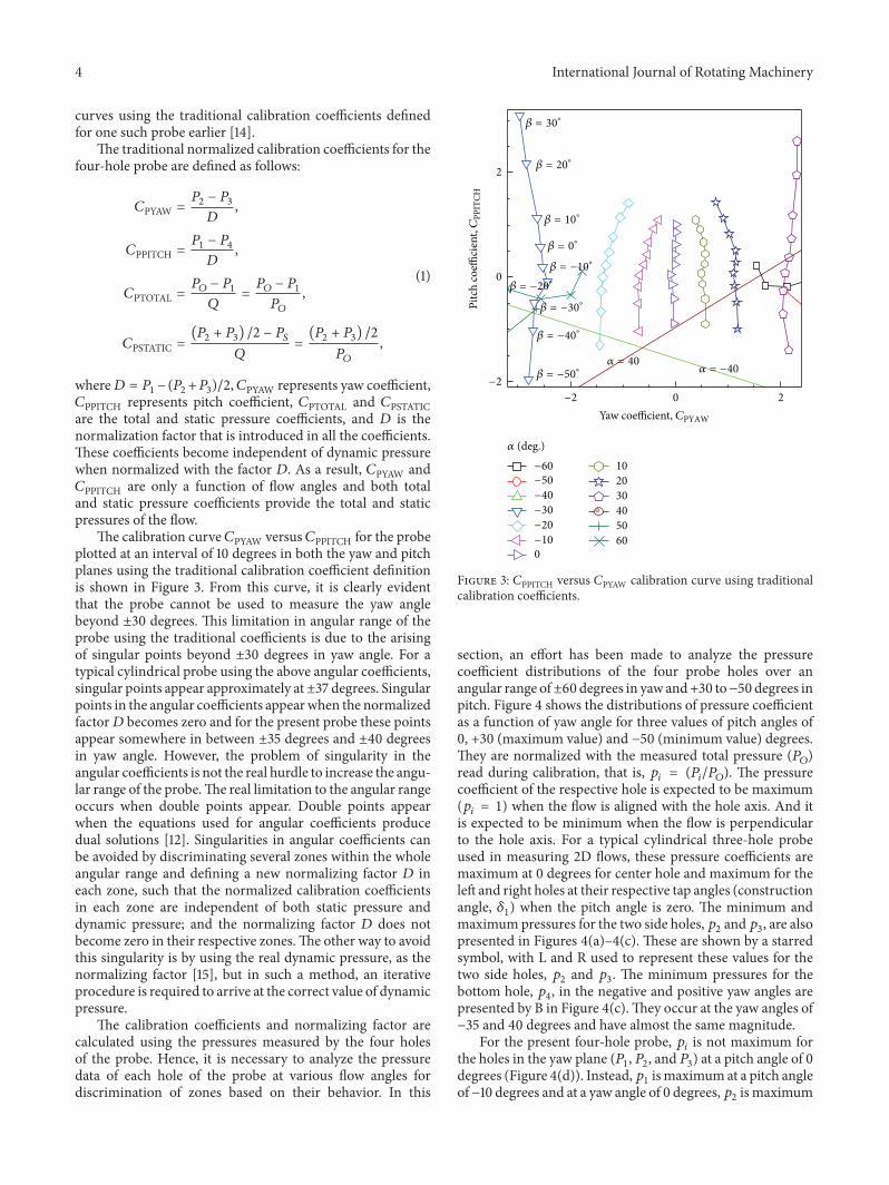
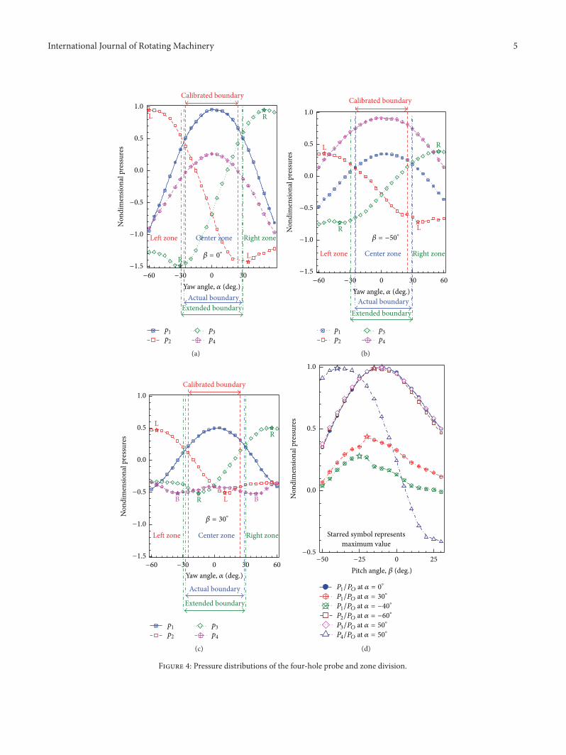
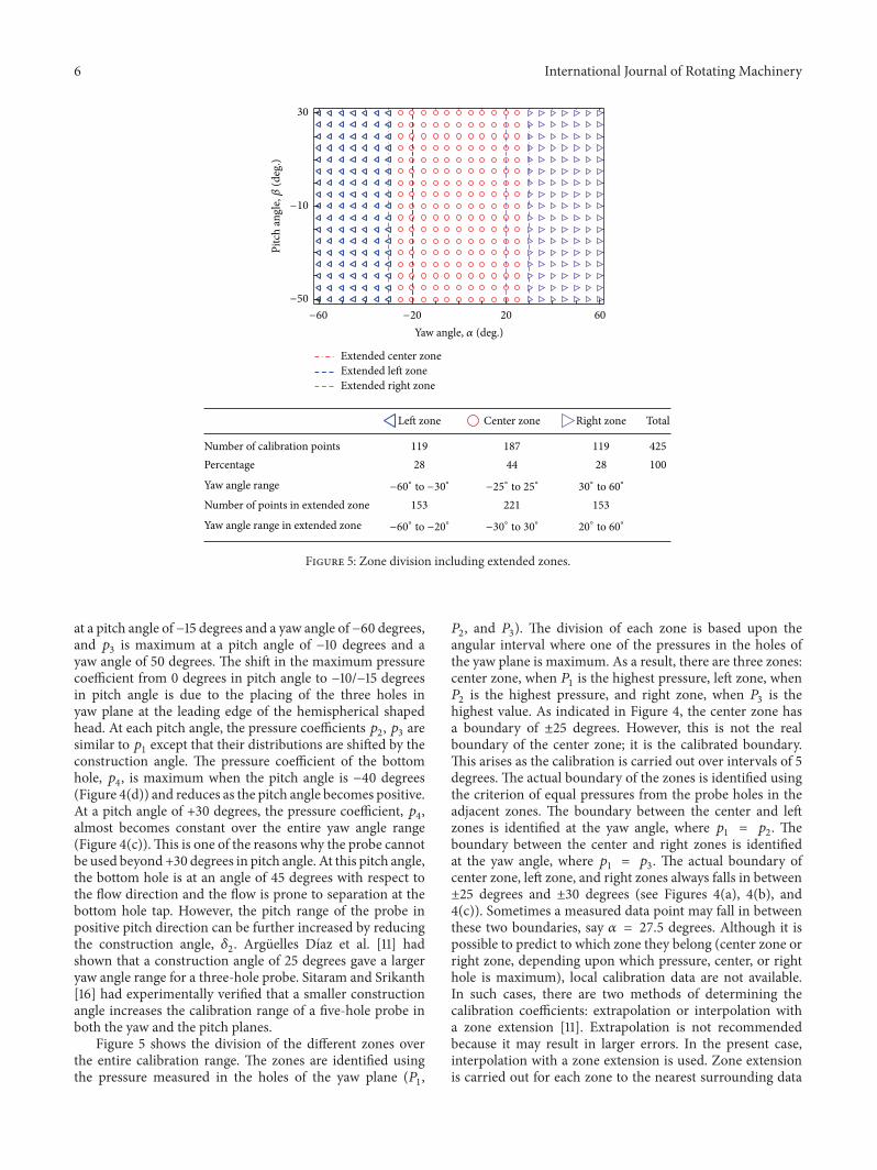
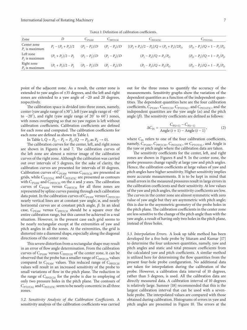
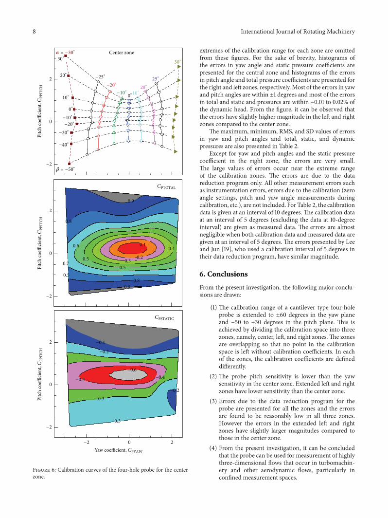
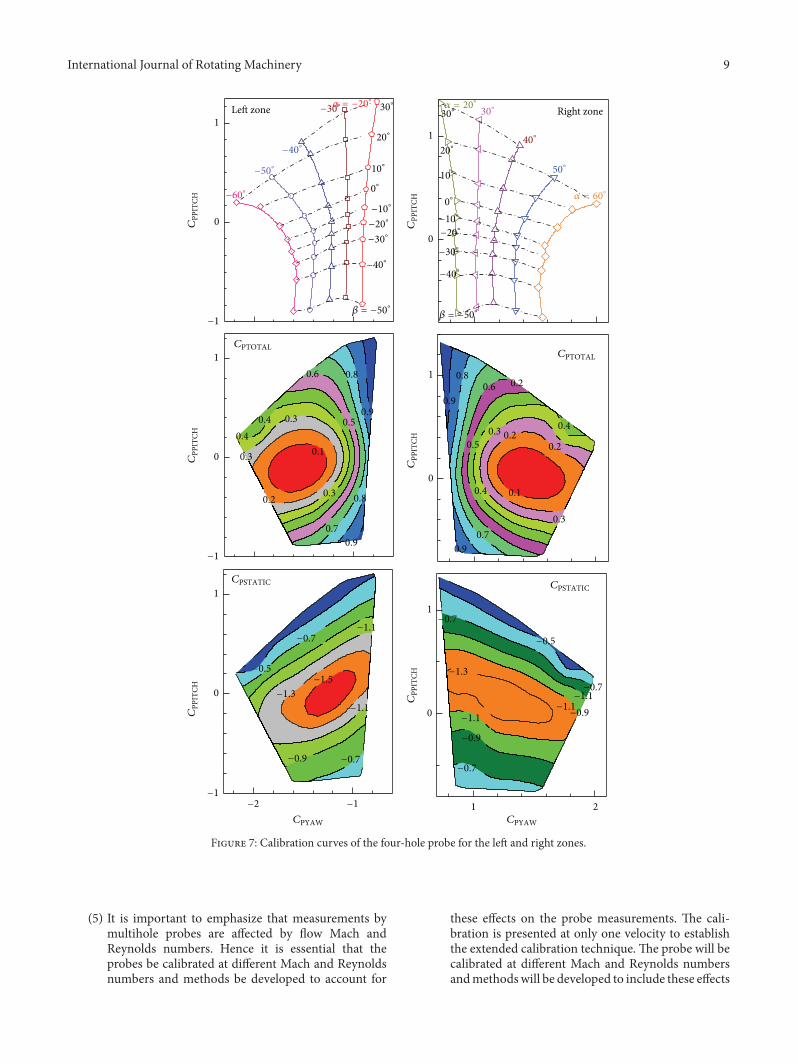
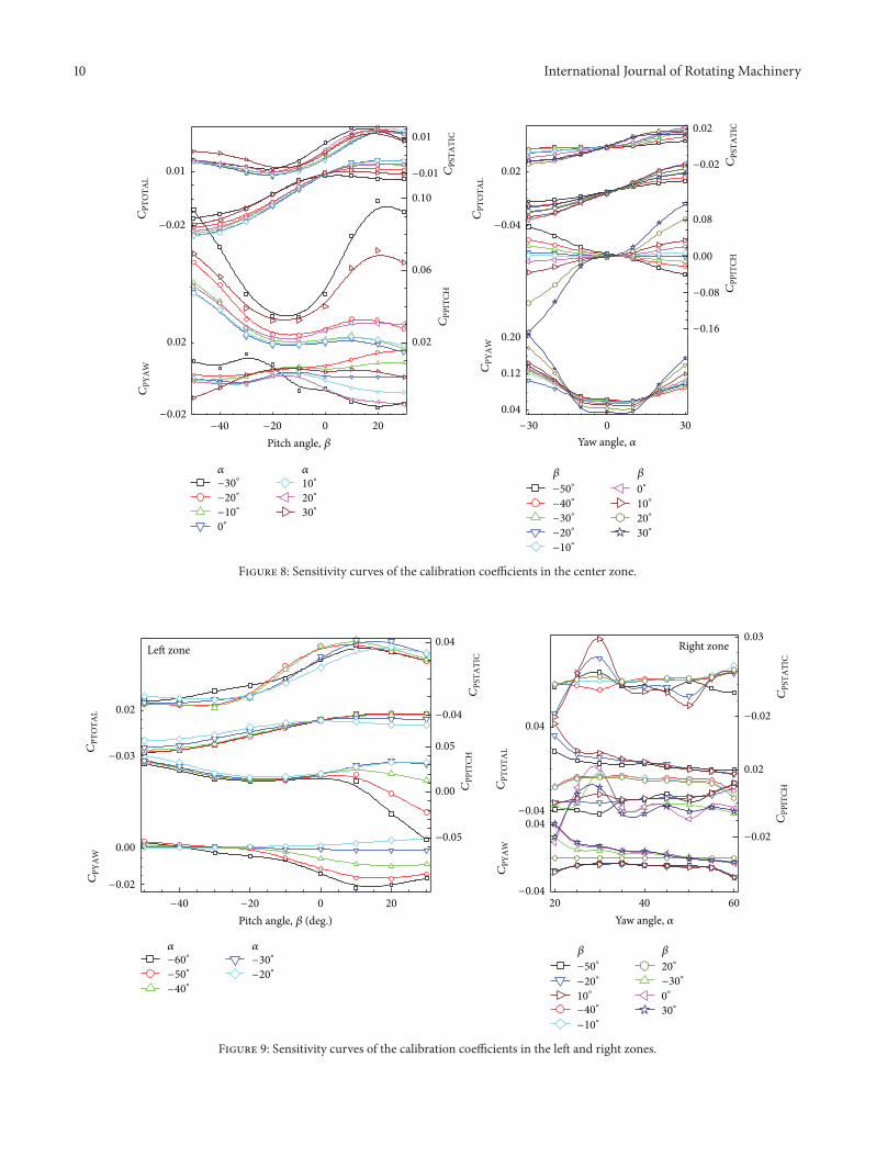
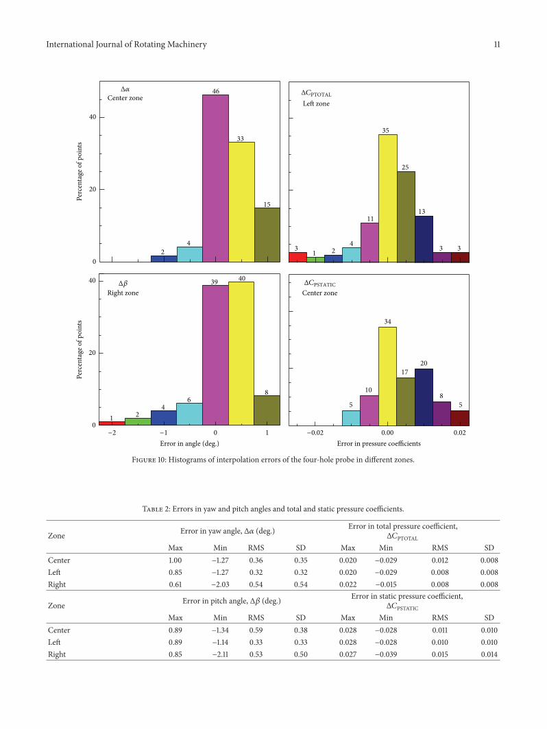

International Journal of
AerospaceEngineeringHindawi Publishing Corporationhttpwwwhindawicom Volume 2014
RoboticsJournal of
Hindawi Publishing Corporationhttpwwwhindawicom Volume 2014
Hindawi Publishing Corporationhttpwwwhindawicom Volume 2014
Active and Passive Electronic Components
Control Scienceand Engineering
Journal of
Hindawi Publishing Corporationhttpwwwhindawicom Volume 2014
International Journal of
RotatingMachinery
Hindawi Publishing Corporationhttpwwwhindawicom Volume 2014
Hindawi Publishing Corporation httpwwwhindawicom
Journal ofEngineeringVolume 2014
Submit your manuscripts athttpwwwhindawicom
VLSI Design
Hindawi Publishing Corporationhttpwwwhindawicom Volume 2014
Hindawi Publishing Corporationhttpwwwhindawicom Volume 2014
Shock and Vibration
Hindawi Publishing Corporationhttpwwwhindawicom Volume 2014
Civil EngineeringAdvances in
Acoustics and VibrationAdvances in
Hindawi Publishing Corporationhttpwwwhindawicom Volume 2014
Hindawi Publishing Corporationhttpwwwhindawicom Volume 2014
Electrical and Computer Engineering
Journal of
Advances inOptoElectronics
Hindawi Publishing Corporation httpwwwhindawicom
Volume 2014
The Scientific World JournalHindawi Publishing Corporation httpwwwhindawicom Volume 2014
SensorsJournal of
Hindawi Publishing Corporationhttpwwwhindawicom Volume 2014
Modelling amp Simulation in EngineeringHindawi Publishing Corporation httpwwwhindawicom Volume 2014
Hindawi Publishing Corporationhttpwwwhindawicom Volume 2014
Chemical EngineeringInternational Journal of Antennas and
Propagation
International Journal of
Hindawi Publishing Corporationhttpwwwhindawicom Volume 2014
Hindawi Publishing Corporationhttpwwwhindawicom Volume 2014
Navigation and Observation
International Journal of
Hindawi Publishing Corporationhttpwwwhindawicom Volume 2014
DistributedSensor Networks
International Journal of