Embed Size (px)
Citation preview
Research ArticleInvestigation of Horizontal Velocity Fields inStirred Vessels with Helical Coils by PIV
Volker Bliem1 and Heyko Jürgen Schultz2
1 Lehrstuhl fur Technische Chemie II, Universitat Duisburg-Essen, 45117 Essen, Germany2 Institute for Coatings and Surface Chemistry (ILOC), University of Applied Sciences Niederrhein,Chemical Engineering/Faculty of Chemistry, Alderstraße 32, 47798 Krefeld, Germany
Correspondence should be addressed to Heyko Jurgen Schultz; heyko [email protected]
Received 23 January 2014; Accepted 27 April 2014; Published 19 May 2014
Academic Editor: Miguel J. Bagajewicz
Copyright © 2014 V. Bliem and H. J. Schultz. This is an open access article distributed under the Creative Commons AttributionLicense, which permits unrestricted use, distribution, and reproduction in any medium, provided the original work is properlycited.
Horizontal velocity flow fields were measured by particle image velocimetry for a stirred vessel with baffles and two helical coils forenlargement of heat transfer area. The investigation was carried out in a cylindrical vessel with flat base and two different stirrers(radial-flow Rushton turbine and axial-flow propeller stirrer). Combined velocity plots for flow fields at different locations arepresented. It was found that helical coils change the flow pattern significantly. Measurements for the axial-flow Rushton turbineshowed a strong deflection by the coils, leading to amainly tangential flow pattern. Behind baffles large areas of unused heat transferarea were found. First results for the axial-flow propeller reveal an extensive absence of fluid movement in the horizontal plane.Improved design considerations for enhanced heat transfer by more compatible equipment compilation are proposed.
1. Introduction
Mixing and stirring processes constitute widely spread andvery important unit operations in chemical and allied indus-tries. Most chemical products are treated at least once by astirring process in an agitated vessel during their lifetime.Therotating impeller within a cylindrical vessel generates a verycomplex, three-dimensional flow structure, which is difficultto measure and quantify. Therefore, the mixing processes arenot understood well in spite of many decades of utilizationand scaling being done by means of semiempirical methods.Thus, solving andmixing-related problems in chemical plantsare usually underrated. Based on estimates of Tatterson et al.[1] amounts of $1–20 billion/year are lost due to mixing-related problems only in the USA.
Special cases of chemical engineering are stirred vesselsequipped with inserts of helical coils. These are helically,coiled pipes built into the vessel with the goal of achievinga higher heat exchange area. A heat transfer medium isconveyed through the additional coils, thereby increasingthe indirect heat transfer between the medium in the vesseland outer heat transfer medium. This approach can, for
example, have safety reasons or is used as a means to reducereaction/process times. Especially in endo- and exothermicprocesses, such as distillations or polymerization reactions,the heat transfer area provided by the vessel jacket is notsufficient to guarantee a safe and economic process. Coils,therefore, disturb the flow structure within the vessel signifi-cantly. First experiments on coils in agitated vessels have beenconducted by Chilton et al. [2] with a flat-paddle impeller.Nagata and Takhimoto [3], Appleton and Brennan [4], andOldshue [5] expanded their work in this field on the widespread Rushton turbine impeller. Oldshue [5], therefore, var-ied the dimensions of impeller and coil diameter and gavefirst recommendations on coil design. Skelland andDimmick[6] examined the flow structure of a propeller impeller onNewton- and non-Newton fluids, however, with a deviatinggeometry compared to other authors. Most studies deal withand recommend radial-flow impellers for application withhelical coils. Poggemann et al. [7] and Kraume [8] give acomprehensive overview. A direct comparison of radial andaxial-flow impellers was conducted by Perarasu et al. [9],showing a considerably smaller heat transfer using the axial-flow propeller impeller.
Hindawi Publishing CorporationInternational Journal of Chemical EngineeringVolume 2014, Article ID 763473, 8 pageshttp://dx.doi.org/10.1155/2014/763473
2 International Journal of Chemical Engineering
This study investigates the flow structures of axial andradial-flow impellers in vessels with helical coils using two-dimensional particle image velocimetry (2D-PIV). As anonintrusive measuring technology to investigate complexflow fields, the application of PIV in science and industrygained significant importance during the past two decades[10]. PIV-studies on the flow field for a pitched blade turbinehave been conducted by Sheng et al. [11], Myers et al. [12], andBakker et al. [13], for the Rushton turbine by Hill et al. [14],Sharp and Adrian [15], Deen and Hjertager [16], Hill et al.[17], and Wang et al. [18], with increasing focus on the smallscale flow around the impeller. Therefore, Atibeni et al. [19]studied the adverse effect of inserts in stirred vessels by useof 2D-PIV and showed the applicability of the technique forinvestigating flow fields in stirred vessels.
Besides experimental investigations, the numerical sim-ulation of stirred tanks has become a powerful tool ofchemical engineering. By the application of computationalfluid dynamics (CFD) researchers can not only save muchmoney through simulation-based, targeted vessel design andminimizing lab-plant studies but also get data which cannotbe obtained from experiments. First simulations of the 2Dflow field in stirred tanks were conducted by Harvey andGreaves [20]. Markatos [21] simulated the mixing of twoliquids under the influence of different stirrer geometries andpresented theoretical predictions of velocities and turbulenceenergy. Since then, the number of articles on the flow field instirred tanks via CFD has increased significantly and estab-lished its own field of research. Although modern computertechnology allows the full three-dimensional simulation of astirred tank involving heat balances and chemical reactions,the validation of simulation results against experimentalmeasurements is still evident. Here, PIV provides necessaryguidance in turbulence modeling and defining boundaryconditions as well as validation and improvement of CFDsimulations. These two areas, CFD and PIV experiments,complement each other perfectly and can lead to a validatedmodel for complex stirred tank reactor design in a mediumterm.
2. Methodology
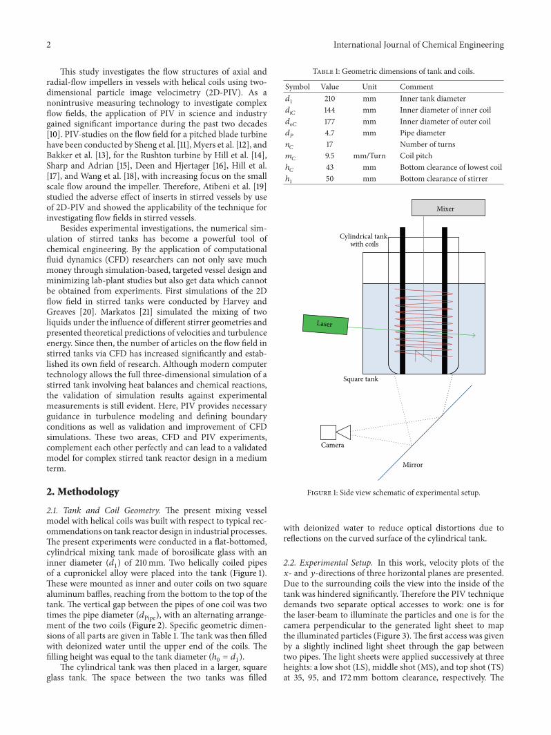
2.1. Tank and Coil Geometry. The present mixing vesselmodel with helical coils was built with respect to typical rec-ommendations on tank reactor design in industrial processes.The present experiments were conducted in a flat-bottomed,cylindrical mixing tank made of borosilicate glass with aninner diameter (𝑑
1) of 210mm. Two helically coiled pipes
of a cupronickel alloy were placed into the tank (Figure 1).These were mounted as inner and outer coils on two squarealuminum baffles, reaching from the bottom to the top of thetank. The vertical gap between the pipes of one coil was twotimes the pipe diameter (𝑑Pipe), with an alternating arrange-ment of the two coils (Figure 2). Specific geometric dimen-sions of all parts are given in Table 1. The tank was then filledwith deionized water until the upper end of the coils. Thefilling height was equal to the tank diameter (ℎ
0= 𝑑1).
The cylindrical tank was then placed in a larger, squareglass tank. The space between the two tanks was filled
Table 1: Geometric dimensions of tank and coils.
Symbol Value Unit Comment𝑑1
210 mm Inner tank diameter𝑑i𝐶 144 mm Inner diameter of inner coil𝑑o𝐶 177 mm Inner diameter of outer coil𝑑𝑃
4.7 mm Pipe diameter𝑛𝐶
17 Number of turns𝑚𝐶
9.5 mm/Turn Coil pitchℎ𝐶
43 mm Bottom clearance of lowest coilℎ1
50 mm Bottom clearance of stirrer
Mirror
Camera
Square tank
Mixer
Cylindrical tank with coils
Laser
Figure 1: Side view schematic of experimental setup.
with deionized water to reduce optical distortions due toreflections on the curved surface of the cylindrical tank.
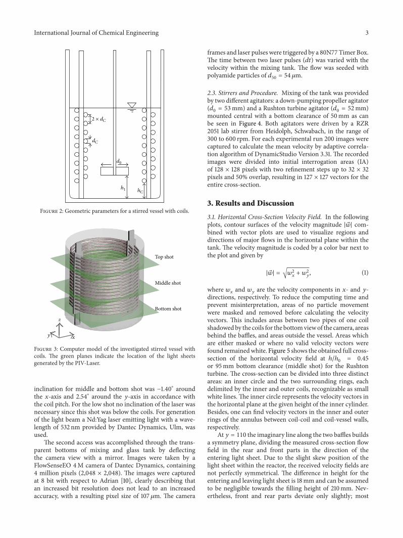
2.2. Experimental Setup. In this work, velocity plots of the𝑥- and 𝑦-directions of three horizontal planes are presented.Due to the surrounding coils the view into the inside of thetank was hindered significantly. Therefore the PIV techniquedemands two separate optical accesses to work: one is forthe laser-beam to illuminate the particles and one is for thecamera perpendicular to the generated light sheet to mapthe illuminated particles (Figure 3).The first access was givenby a slightly inclined light sheet through the gap betweentwo pipes. The light sheets were applied successively at threeheights: a low shot (LS), middle shot (MS), and top shot (TS)at 35, 95, and 172mm bottom clearance, respectively. The
International Journal of Chemical Engineering 3
2 × dC
dC
d0
h1 hC
Figure 2: Geometric parameters for a stirred vessel with coils.
Bottom shot
Top shot
Middle shot
x
z
y
BoBBBBBBB
To
MMMMMMM
z
Figure 3: Computer model of the investigated stirred vessel withcoils. The green planes indicate the location of the light sheetsgenerated by the PIV-Laser.
inclination for middle and bottom shot was −1.40∘ aroundthe 𝑥-axis and 2.54∘ around the 𝑦-axis in accordance withthe coil pitch. For the low shot no inclination of the laser wasnecessary since this shot was below the coils. For generationof the light beam a Nd:Yag laser emitting light with a wave-length of 532 nm provided by Dantec Dynamics, Ulm, wasused.
The second access was accomplished through the trans-parent bottoms of mixing and glass tank by deflectingthe camera view with a mirror. Images were taken by aFlowSenseEO 4M camera of Dantec Dynamics, containing4 million pixels (2,048 × 2,048). The images were capturedat 8 bit with respect to Adrian [10], clearly describing thatan increased bit resolution does not lead to an increasedaccuracy, with a resulting pixel size of 107 𝜇m. The camera
frames and laser pulses were triggered by a 80N77 Timer Box.The time between two laser pulses (𝑑𝑡) was varied with thevelocity within the mixing tank. The flow was seeded withpolyamide particles of 𝑑
50= 54 𝜇m.
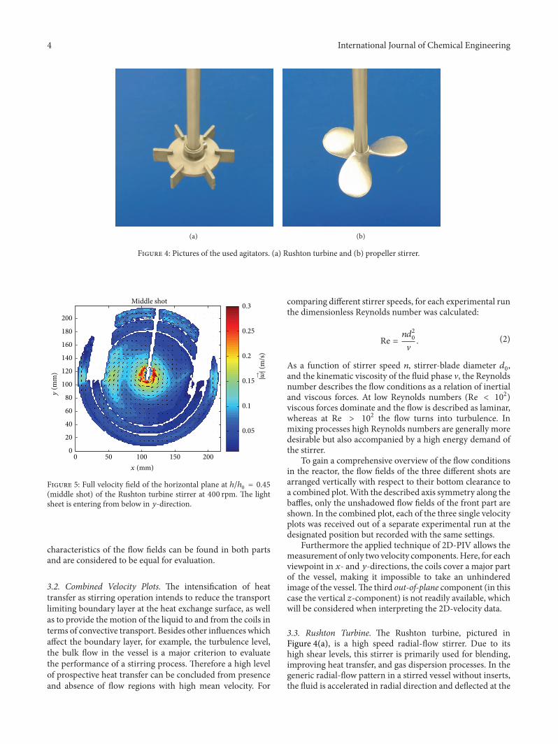
2.3. Stirrers and Procedure. Mixing of the tank was providedby two different agitators: a down-pumping propeller agitator(𝑑0= 53mm) and a Rushton turbine agitator (𝑑
0= 52mm)
mounted central with a bottom clearance of 50mm as canbe seen in Figure 4. Both agitators were driven by a RZR2051 lab stirrer from Heidolph, Schwabach, in the range of300 to 600 rpm. For each experimental run 200 images werecaptured to calculate the mean velocity by adaptive correla-tion algorithm of DynamicStudio Version 3.31. The recordedimages were divided into initial interrogation areas (IA)of 128 × 128 pixels with two refinement steps up to 32 × 32pixels and 50% overlap, resulting in 127 × 127 vectors for theentire cross-section.
3. Results and Discussion
3.1. Horizontal Cross-Section Velocity Field. In the followingplots, contour surfaces of the velocity magnitude |��| com-bined with vector plots are used to visualize regions anddirections of major flows in the horizontal plane within thetank. The velocity magnitude is coded by a color bar next tothe plot and given by
|��| = √𝑤2𝑥+ 𝑤2𝑦, (1)
where 𝑤𝑥and 𝑤
𝑦are the velocity components in 𝑥- and 𝑦-
directions, respectively. To reduce the computing time andprevent misinterpretation, areas of no particle movementwere masked and removed before calculating the velocityvectors. This includes areas between two pipes of one coilshadowedby the coils for the bottomviewof the camera, areasbehind the baffles, and areas outside the vessel. Areas whichare either masked or where no valid velocity vectors werefound remainedwhite. Figure 5 shows the obtained full cross-section of the horizontal velocity field at ℎ/ℎ
0= 0.45
or 95mm bottom clearance (middle shot) for the Rushtonturbine. The cross-section can be divided into three distinctareas: an inner circle and the two surrounding rings, eachdelimited by the inner and outer coils, recognizable as smallwhite lines. The inner circle represents the velocity vectors inthe horizontal plane at the given height of the inner cylinder.Besides, one can find velocity vectors in the inner and outerrings of the annulus between coil-coil and coil-vessel walls,respectively.
At 𝑦 = 110 the imaginary line along the two baffles buildsa symmetry plane, dividing the measured cross-section flowfield in the rear and front parts in the direction of theentering light sheet. Due to the slight skew position of thelight sheet within the reactor, the received velocity fields arenot perfectly symmetrical. The difference in height for theentering and leaving light sheet is 18mm and can be assumedto be negligible towards the filling height of 210mm. Nev-ertheless, front and rear parts deviate only slightly; most
4 International Journal of Chemical Engineering
(a) (b)
Figure 4: Pictures of the used agitators. (a) Rushton turbine and (b) propeller stirrer.
180
160
140
120
100
80
60
40
200
20
00 50 100 150 200
0.25
0.2
0.15
0.1
0.05
0.3Middle shot
|→ w|
(m/s
)
x (mm)
y(m
m)
Figure 5: Full velocity field of the horizontal plane at ℎ/ℎ0= 0.45
(middle shot) of the Rushton turbine stirrer at 400 rpm. The lightsheet is entering from below in 𝑦-direction.
characteristics of the flow fields can be found in both partsand are considered to be equal for evaluation.
3.2. Combined Velocity Plots. The intensification of heattransfer as stirring operation intends to reduce the transportlimiting boundary layer at the heat exchange surface, as wellas to provide the motion of the liquid to and from the coils interms of convective transport. Besides other influences whichaffect the boundary layer, for example, the turbulence level,the bulk flow in the vessel is a major criterion to evaluatethe performance of a stirring process. Therefore a high levelof prospective heat transfer can be concluded from presenceand absence of flow regions with high mean velocity. For
comparing different stirrer speeds, for each experimental runthe dimensionless Reynolds number was calculated:
Re =𝑛𝑑2
0
V. (2)
As a function of stirrer speed 𝑛, stirrer-blade diameter 𝑑0,
and the kinematic viscosity of the fluid phase V, the Reynoldsnumber describes the flow conditions as a relation of inertialand viscous forces. At low Reynolds numbers (Re < 102)viscous forces dominate and the flow is described as laminar,whereas at Re > 102 the flow turns into turbulence. Inmixing processes high Reynolds numbers are generally moredesirable but also accompanied by a high energy demand ofthe stirrer.
To gain a comprehensive overview of the flow conditionsin the reactor, the flow fields of the three different shots arearranged vertically with respect to their bottom clearance toa combined plot.With the described axis symmetry along thebaffles, only the unshadowed flow fields of the front part areshown. In the combined plot, each of the three single velocityplots was received out of a separate experimental run at thedesignated position but recorded with the same settings.
Furthermore the applied technique of 2D-PIV allows themeasurement of only two velocity components.Here, for eachviewpoint in 𝑥- and 𝑦-directions, the coils cover a major partof the vessel, making it impossible to take an unhinderedimage of the vessel.The third out-of-plane component (in thiscase the vertical 𝑧-component) is not readily available, whichwill be considered when interpreting the 2D-velocity data.
3.3. Rushton Turbine. The Rushton turbine, pictured inFigure 4(a), is a high speed radial-flow stirrer. Due to itshigh shear levels, this stirrer is primarily used for blending,improving heat transfer, and gas dispersion processes. In thegeneric radial-flow pattern in a stirred vessel without inserts,the fluid is accelerated in radial direction and deflected at the
International Journal of Chemical Engineering 5
vessel wall into an upper and lower recirculation loop. Thisstirrer is most effective in low-viscosity liquids and baffledvessels. In case of higher viscosities the fluid is set in primarilytangential motion, according to Zlokarnik [22].
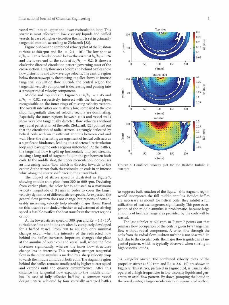
Figure 6 shows the combined velocity plot of the Rushtonturbine at 500 rpm and Re = 2.4 ⋅ 104. The low shot atℎ/ℎ0= 0.17 is closely located below the stirrer at ℎ
1/ℎ0= 0.26
and the lower end of the coils at ℎ𝐶/ℎ0= 0.2. It shows a
clockwise directed circulation pattern governing most of thecross-section. Only flow areas before and behind baffles showflow distortions and a low average velocity.The central regionbelow the area swept by themoving impeller shows an intensetangential circulation flow. Outside the central region thetangential velocity component is decreasing and passing intoa stronger radial velocity component.
Middle and top shots in Figure 6 at ℎ/ℎ0= 0.45 and
ℎ/ℎ0= 0.82, respectively, intersect with the helical pipes,
recognizable on the inner rings of missing velocity vectors.The overall intensities are relatively low, compared to the lowshot. Tangentially directed velocity vectors are dominating.Especially the outer regions between coils and vessel wallsshow very low tangentially directed flow velocities withoutany radial penetration of the coils. Zlokarnik [22] pointed outthat the circulation of radial stirrers is strongly deflected byhelical coils with an insufficient annulus between coil andwall. Here, the alternating arrangement of helical coils acts asa significant hindrance, leading to a shortened recirculationloop and leaving the outer regions untouched. At the baffles,the tangential flow is split up horizontally into two streams,causing a long trail of stagnant fluid in the gap between bothcoils. In the middle shot, the upper recirculation loop causesan increasing radial-flow which is directed inwards to thecenter. At the stirrer shaft, the recirculation ends in an intensewhirl along the stirrer shaft back to the stirrer blade.
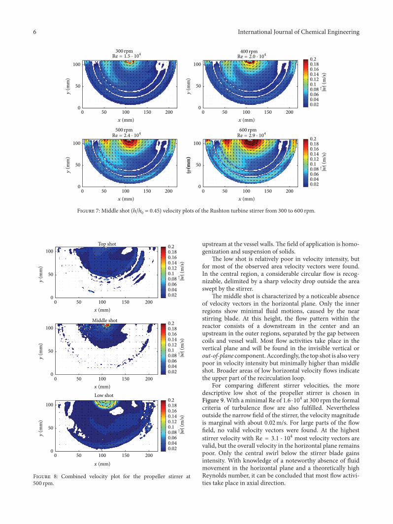
The impact of stirrer speed is illustrated in Figure 7,showing middle shot plots from 300 to 600 rpm. Deviatingfrom earlier plots, the color bar is adjusted to a maximumvelocity magnitude of 0.2m/s in order to cover the largervelocity dynamics of different stirrer speeds. As expected, thegeneral flow pattern does not change, but regions of consid-erably increasing velocity help identify major flows. Basedon this it can be concluded whether an adjustment of stirringspeed is feasible to affect the heat transfer in the target regionsor not.
At the lowest stirrer speed of 300 rpm and Re = 1.5 ⋅ 104,turbulence flow conditions are already completely developedfor a baffled vessel. From 300 to 400 rpm only minimalchanges occur, when the intensity of the redirected flowbehind the baffles increases. Important changes take placeat the annulus of outer coil and vessel wall, where the flowincreases significantly, whereas the inner flow structureschange less in intensity. This resulting stronger tangentialflow in the outer annulus is marked by a sharp velocity droptowards themiddle annulus of both coils.The stagnant regionbehind the baffles remains unaffected by higher stirrer speedand extends until the quarter circumference. After thisdistance the tangential flow expands to the middle annu-lus. In case of fully effective baffling—a common vesseldesign criteria achieved by four vertically arranged baffles
0 50 100 150 2000
50
1000.250.20.150.10.05
0.3
Middle shot
Top shot
Low shot
0 50 100 150 2000
50
100
0 50 100 150 2000
50
100
|→ w|
(m/s
)
0.250.20.150.10.05
0.3
|→ w|
(m/s
)
0.250.20.150.10.05
0.3
|→ w|
(m/s
)
x (mm)
x (mm)
x (mm)
y(m
m)
y(m
m)
y(m
m)
Figure 6: Combined velocity plot for the Rushton turbine at500 rpm.
to suppress bulk rotation of the liquid—this stagnant regionwould incorporate the full middle annulus. Besides bafflesare necessary as mount for helical coils, they inhibit a fullutilization of heat exchange area significantly.This poor occu-pation of the middle annulus is problematic, because largeamounts of heat exchange area provided by the coils will bewasted.
The last subplot at 600 rpm in Figure 7 points out thatprimary flow occupation of the coils is given by a tangentialflow without radial component. A cross-flow through thecoils from the radial-flow Rushton turbine is not observed. Infact, due to the circular coils, themajor flow is guided in a tan-gential pattern, which is typically observed when stirring inhigh viscous liquids.
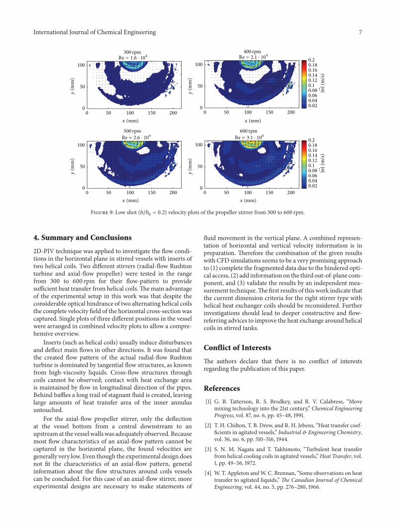
3.4. Propeller Stirrer. The combined velocity plots of thepropeller stirrer at 500 rpm and Re = 2.6 ⋅ 104 are shown inFigure 8. This stirrer, pictured in Figure 5(b), is usually alsooperated at high frequencies in low-viscosity liquids and gen-erates an axial-flow pattern. By down-pumping the liquid inthe vessel center, a large circulation loop is generated with an
6 International Journal of Chemical Engineering
0.180.160.140.12
0.02
0.2
0.10.080.060.04
|→ w|
(m/s
)
0.180.160.140.12
0.02
0.2
0.10.080.060.04
|→ w|
(m/s
)
0 50 100 150 2000
50
100
300 rpmRe = 1.5 · 104
0 50 100 150 2000
50
100
500 rpmRe = 2.4 · 104
0 50 100 150 2000
50
100
600 rpmRe = 2.9 · 104
(y/m
m)
0 50 100 150 2000
50
100
400 rpmRe = 2.0 · 104
x (mm)
x (mm) x (mm)
x (mm)
y(m
m)
y(m
m)
y(m
m)
y(m
m)
Figure 7: Middle shot (ℎ/ℎ0= 0.45) velocity plots of the Rushton turbine stirrer from 300 to 600 rpm.
0 50 100 150 2000
50
100
0 50 100 150 2000
50
100
0 50 100 150 2000
50
100
Middle shot
Top shot
Low shot
0.180.160.140.12
0.02
0.2
0.10.080.060.04
|→ w|
(m/s
)
0.180.160.140.12
0.02
0.2
0.10.080.060.04
|→ w|
(m/s
)
0.180.160.140.12
0.02
0.2
0.10.080.060.04
|→ w|
(m/s
)
x (mm)
y(m
m)
x (mm)
y(m
m)
x (mm)
y(m
m)
Figure 8: Combined velocity plot for the propeller stirrer at500 rpm.
upstream at the vessel walls.The field of application is homo-genization and suspension of solids.
The low shot is relatively poor in velocity intensity, butfor most of the observed area velocity vectors were found.In the central region, a considerable circular flow is recog-nizable, delimited by a sharp velocity drop outside the areaswept by the stirrer.
The middle shot is characterized by a noticeable absenceof velocity vectors in the horizontal plane. Only the innerregions show minimal fluid motions, caused by the nearstirring blade. At this height, the flow pattern within thereactor consists of a downstream in the center and anupstream in the outer regions, separated by the gap betweencoils and vessel wall. Most flow activities take place in thevertical plane and will be found in the invisible vertical orout-of-plane component. Accordingly, the top shot is also verypoor in velocity intensity but minimally higher than middleshot. Broader areas of low horizontal velocity flows indicatethe upper part of the recirculation loop.
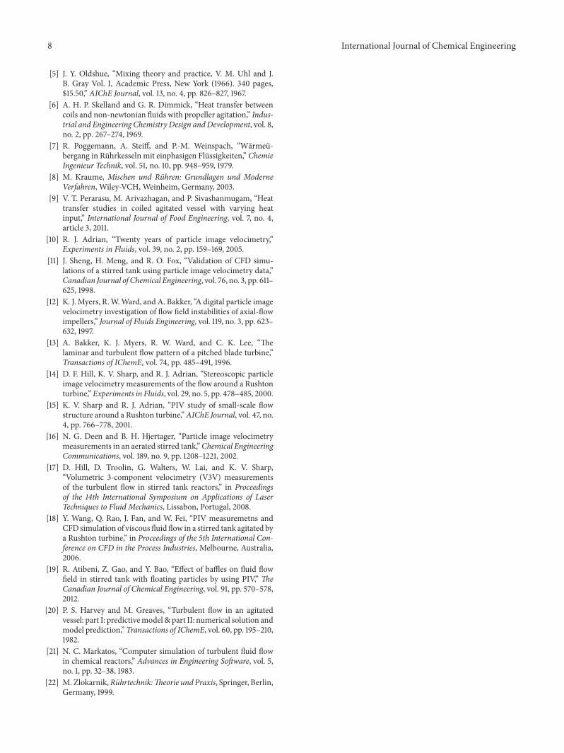
For comparing different stirrer velocities, the moredescriptive low shot of the propeller stirrer is chosen inFigure 9.With aminimal Re of 1.6 ⋅104 at 300 rpm the formalcriteria of turbulence flow are also fulfilled. Neverthelessoutside the narrow field of the stirrer, the velocity magnitudeis marginal with about 0.02m/s. For large parts of the flowfield, no valid velocity vectors were found. At the higheststirrer velocity with Re = 3.1 ⋅ 104 most velocity vectors arevalid, but the overall velocity in the horizontal plane remainspoor. Only the central swirl below the stirrer blade gainsintensity. With knowledge of a noteworthy absence of fluidmovement in the horizontal plane and a theoretically highReynolds number, it can be concluded that most flow activi-ties take place in axial direction.
International Journal of Chemical Engineering 7
0 50 100 150 2000
50
100
300 rpmRe = 1.6 · 104
0 50 100 150 2000
50
100
400 rpmRe = 2.1 · 104
0 50 100 150 2000
50
100
500 rpmRe = 2.6 · 104
0 50 100 150 2000
50
100
600 rpmRe = 3.1 · 104
0.180.160.140.12
0.02
0.2
0.10.080.060.04
|→ w|
(m/s
)
0.180.160.140.12
0.02
0.2
0.10.080.060.04
|→ w|
(m/s
)
x (mm)
x (mm) x (mm)
x (mm)
y(m
m)
y(m
m)
y(m
m)
y(m
m)
Figure 9: Low shot (ℎ/ℎ0= 0.2) velocity plots of the propeller stirrer from 300 to 600 rpm.
4. Summary and Conclusions
2D-PIV technique was applied to investigate the flow condi-tions in the horizontal plane in stirred vessels with inserts oftwo helical coils. Two different stirrers (radial-flow Rushtonturbine and axial-flow propeller) were tested in the rangefrom 300 to 600 rpm for their flow-pattern to providesufficient heat transfer from helical coils.Themain advantageof the experimental setup in this work was that despite theconsiderable optical hindrance of two alternating helical coilsthe complete velocity field of the horizontal cross-section wascaptured. Single plots of three different positions in the vesselwere arranged in combined velocity plots to allow a compre-hensive overview.
Inserts (such as helical coils) usually induce disturbancesand deflect main flows in other directions. It was found thatthe created flow pattern of the actual radial-flow Rushtonturbine is dominated by tangential flow structures, as knownfrom high-viscosity liquids. Cross-flow structures throughcoils cannot be observed; contact with heat exchange areais maintained by flow in longitudinal direction of the pipes.Behind baffles a long trail of stagnant fluid is created, leavinglarge amounts of heat transfer area of the inner annulusuntouched.
For the axial-flow propeller stirrer, only the deflectionat the vessel bottom from a central downstream to anupstreamat the vessel walls was adequately observed. Becausemost flow characteristics of an axial-flow pattern cannot becaptured in the horizontal plane, the found velocities aregenerally very low. Even though the experimental design doesnot fit the characteristics of an axial-flow pattern, generalinformation about the flow structures around coils vesselscan be concluded. For this case of an axial-flow stirrer, moreexperimental designs are necessary to make statements of
fluid movement in the vertical plane. A combined represen-tation of horizontal and vertical velocity information is inpreparation. Therefore the combination of the given resultswith CFD simulations seems to be a very promising approachto (1) complete the fragmented data due to the hindered opti-cal access, (2) add information on the third out-of-plane com-ponent, and (3) validate the results by an independent mea-surement technique.Thefirst results of this work indicate thatthe current dimension criteria for the right stirrer type withhelical heat exchanger coils should be reconsidered. Furtherinvestigations should lead to deeper constructive and flow-referring advices to improve the heat exchange around helicalcoils in stirred tanks.
Conflict of Interests
The authors declare that there is no conflict of interestsregarding the publication of this paper.
References
[1] G. B. Tatterson, R. S. Brodkey, and R. V. Calabrese, “Movemixing technology into the 21st century,” Chemical EngineeringProgress, vol. 87, no. 6, pp. 45–48, 1991.
[2] T. H. Chilton, T. B. Drew, and R. H. Jebens, “Heat transfer coef-ficients in agitated vessels,” Industrial & Engineering Chemistry,vol. 36, no. 6, pp. 510–516, 1944.
[3] S. N. M. Nagata and T. Takhimoto, “Turbulent heat transferfrom helical cooling coils in agitated vessels,”Heat Transfer, vol.1, pp. 49–56, 1972.
[4] W. T. Appleton andW. C. Brennan, “Some observations on heattransfer to agitated liquids,” The Canadian Journal of ChemicalEngineering, vol. 44, no. 5, pp. 276–280, 1966.
8 International Journal of Chemical Engineering
[5] J. Y. Oldshue, “Mixing theory and practice, V. M. Uhl and J.B. Gray Vol. I, Academic Press, New York (1966). 340 pages,$15.50,” AIChE Journal, vol. 13, no. 4, pp. 826–827, 1967.
[6] A. H. P. Skelland and G. R. Dimmick, “Heat transfer betweencoils and non-newtonian fluids with propeller agitation,” Indus-trial and Engineering Chemistry Design and Development, vol. 8,no. 2, pp. 267–274, 1969.
[7] R. Poggemann, A. Steiff, and P.-M. Weinspach, “Warmeu-bergang in Ruhrkesseln mit einphasigen Flussigkeiten,” ChemieIngenieur Technik, vol. 51, no. 10, pp. 948–959, 1979.
[8] M. Kraume, Mischen und Ruhren: Grundlagen und ModerneVerfahren, Wiley-VCH, Weinheim, Germany, 2003.
[9] V. T. Perarasu, M. Arivazhagan, and P. Sivashanmugam, “Heattransfer studies in coiled agitated vessel with varying heatinput,” International Journal of Food Engineering, vol. 7, no. 4,article 3, 2011.
[10] R. J. Adrian, “Twenty years of particle image velocimetry,”Experiments in Fluids, vol. 39, no. 2, pp. 159–169, 2005.
[11] J. Sheng, H. Meng, and R. O. Fox, “Validation of CFD simu-lations of a stirred tank using particle image velocimetry data,”Canadian Journal of Chemical Engineering, vol. 76, no. 3, pp. 611–625, 1998.
[12] K. J. Myers, R.W.Ward, and A. Bakker, “A digital particle imagevelocimetry investigation of flow field instabilities of axial-flowimpellers,” Journal of Fluids Engineering, vol. 119, no. 3, pp. 623–632, 1997.
[13] A. Bakker, K. J. Myers, R. W. Ward, and C. K. Lee, “Thelaminar and turbulent flow pattern of a pitched blade turbine,”Transactions of IChemE, vol. 74, pp. 485–491, 1996.
[14] D. F. Hill, K. V. Sharp, and R. J. Adrian, “Stereoscopic particleimage velocimetry measurements of the flow around a Rushtonturbine,” Experiments in Fluids, vol. 29, no. 5, pp. 478–485, 2000.
[15] K. V. Sharp and R. J. Adrian, “PIV study of small-scale flowstructure around a Rushton turbine,”AIChE Journal, vol. 47, no.4, pp. 766–778, 2001.
[16] N. G. Deen and B. H. Hjertager, “Particle image velocimetrymeasurements in an aerated stirred tank,”Chemical EngineeringCommunications, vol. 189, no. 9, pp. 1208–1221, 2002.
[17] D. Hill, D. Troolin, G. Walters, W. Lai, and K. V. Sharp,“Volumetric 3-component velocimetry (V3V) measurementsof the turbulent flow in stirred tank reactors,” in Proceedingsof the 14th International Symposium on Applications of LaserTechniques to Fluid Mechanics, Lissabon, Portugal, 2008.
[18] Y. Wang, Q. Rao, J. Fan, and W. Fei, “PIV measuremetns andCFD simulation of viscous fluid flow in a stirred tank agitated bya Rushton turbine,” in Proceedings of the 5th International Con-ference on CFD in the Process Industries, Melbourne, Australia,2006.
[19] R. Atibeni, Z. Gao, and Y. Bao, “Effect of baffles on fluid flowfield in stirred tank with floating particles by using PIV,” TheCanadian Journal of Chemical Engineering, vol. 91, pp. 570–578,2012.
[20] P. S. Harvey and M. Greaves, “Turbulent flow in an agitatedvessel: part I: predictivemodel & part II: numerical solution andmodel prediction,” Transactions of IChemE, vol. 60, pp. 195–210,1982.
[21] N. C. Markatos, “Computer simulation of turbulent fluid flowin chemical reactors,” Advances in Engineering Software, vol. 5,no. 1, pp. 32–38, 1983.
[22] M. Zlokarnik,Ruhrtechnik:Theorie und Praxis, Springer, Berlin,Germany, 1999.

International Journal of
AerospaceEngineeringHindawi Publishing Corporationhttp://www.hindawi.com Volume 2014
RoboticsJournal of
Hindawi Publishing Corporationhttp://www.hindawi.com Volume 2014
Hindawi Publishing Corporationhttp://www.hindawi.com Volume 2014
Active and Passive Electronic Components
Control Scienceand Engineering
Journal of
Hindawi Publishing Corporationhttp://www.hindawi.com Volume 2014
International Journal of
RotatingMachinery
Hindawi Publishing Corporationhttp://www.hindawi.com Volume 2014
Hindawi Publishing Corporation http://www.hindawi.com
Journal ofEngineeringVolume 2014
Submit your manuscripts athttp://www.hindawi.com
VLSI Design
Hindawi Publishing Corporationhttp://www.hindawi.com Volume 2014
Hindawi Publishing Corporationhttp://www.hindawi.com Volume 2014
Shock and Vibration
Hindawi Publishing Corporationhttp://www.hindawi.com Volume 2014
Civil EngineeringAdvances in
Acoustics and VibrationAdvances in
Hindawi Publishing Corporationhttp://www.hindawi.com Volume 2014
Hindawi Publishing Corporationhttp://www.hindawi.com Volume 2014
Electrical and Computer Engineering
Journal of
Advances inOptoElectronics
Hindawi Publishing Corporation http://www.hindawi.com
Volume 2014
The Scientific World JournalHindawi Publishing Corporation http://www.hindawi.com Volume 2014
SensorsJournal of
Hindawi Publishing Corporationhttp://www.hindawi.com Volume 2014
Modelling & Simulation in EngineeringHindawi Publishing Corporation http://www.hindawi.com Volume 2014
Hindawi Publishing Corporationhttp://www.hindawi.com Volume 2014
Chemical EngineeringInternational Journal of Antennas and
Propagation
International Journal of
Hindawi Publishing Corporationhttp://www.hindawi.com Volume 2014
Hindawi Publishing Corporationhttp://www.hindawi.com Volume 2014
Navigation and Observation
International Journal of
Hindawi Publishing Corporationhttp://www.hindawi.com Volume 2014
DistributedSensor Networks
International Journal of