Embed Size (px)
Citation preview
Research ArticleModeling Validation and Control of ElectronicallyActuated Pitman Arm Steering for Armored Vehicle
Vimal Rau Aparow Khisbullah Hudha Zulkiffli Abd KadirMegat Mohamad Hamdan Megat Ahmad and Shohaimi Abdullah
Department of Mechanical Engineering Faculty of Engineering National Defense University of Malaysia (NDUM)Kem Sungai Besi 57000 Kuala Lumpur Malaysia
Correspondence should be addressed to Vimal Rau Aparow vimalrau87vbgmailcom
Received 24 October 2015 Revised 5 March 2016 Accepted 14 March 2016
Academic Editor Radu Danescu
Copyright copy 2016 Vimal Rau Aparow et al This is an open access article distributed under the Creative Commons AttributionLicense which permits unrestricted use distribution and reproduction in any medium provided the original work is properlycited
In this study 2 DOF mathematical models of Pitman arm steering system are derived using Newtonrsquos law of motion and modeledin MATLABSIMULINK software The developed steering model is included with a DC motor model which is directly attachedto the steering column The Pitman arm steering model is then validated with actual Pitman arm steering test rig using variouslateral inputs such as double lane change step steer and slalom test Meanwhile a position tracking control method has been usedin order to evaluate the effectiveness of the validated model to be implemented in active safety system of a heavy vehicle Thesimilar method has been used to test the actual Pitman arm steering mechanism using hardware-in-the-loop simulation (HILS)technique Additional friction compensation is added in the HILS technique in order to minimize the frictional effects that occurin the mechanical configuration of the DCmotor and Pitman arm steeringThe performance of the electronically actuated Pitmanarm steering system can be used to develop a firing-on-the-move actuator (FOMA) for an armored vehicleThe FOMA can be usedas an active safety system to reject unwanted yaw motion due to the firing force
1 Introduction
Recently automotive researchers have focused their workon the advanced technology of steering system to increasethe safety system of a vehicle [1ndash3] However most of theadvanced researches are mainly concentrated in a passengervehicle A number of researches have been carried out in thedevelopment of active safety system using rack and pinionsteering configuration An active front wheel steering systemusing rack and pinion configuration has been developedby automotive developers BMW [4] This invention allowsdriver-independent steering system by intervening at thefront axle using the mechanical link between the steeringwheel and the front axle The system is supported withdouble planetary gear and an actuatedDCmotorMeanwhileother researchers also actively involved in implementationof the active front wheel steering system as a vehicle yawstability control method [5] This method has been usedto reject the unwanted yaw motion due to aerodynamic
disturbanceThe similar type of active steering has been usedin the development of direct yaw moment control and alsoadvanced driver support technology [6]
Steering system using rack and pinion configuration alsohas been used to develop electric power assisted system(EPAS) for passenger vehicle [7] The EPAS has been usedto design an active disturbance rejection control to reducethe steering torque exerted by the driver due to external sidewind force Other automotive researchers as stated in [8 9]focused on the safety system of steering system using steer-by-wire technologyThis technology is mainly invented froman aircraft system known as fly-by-wire Besides there arealso some studies related to hardware-in-the-loop simulation(HILS) to investigate the performance of the active frontwheel steering to develop yaw rejection control system usingrack and pinion test rig [10ndash12] However most of theprevious work is mainly related to rack and pinion type ofsteering systemwhich is basically implemented in a passengervehicle
Hindawi Publishing CorporationInternational Journal of Vehicular TechnologyVolume 2016 Article ID 2175204 12 pageshttpdxdoiorg10115520162175204
2 International Journal of Vehicular Technology
Meanwhile research works related on the Pitman armsteering system are very much limited Commercial heavyvehicle research in California has initiated research on thesafety performance of heavy vehicle system using an actualtruck [13] The research entirely focuses on the modelingdevelopment of heavy vehicle using ADAMS software andvalidation with an actual vehicle However the validation onPitman arm steering is not included in this work Recently anactive independent front steering (AIFS) has been developedto compare with the conventional active front wheel steeringsystem [14] This active system used the truck model todevelop active independent front steering system but hasneglected the Pitman arm steering model Thus it clearlyshows that most of the automotive researchers have notconsidered the performance evaluation of the Pitman armsteering system before it can be implemented in virtual oractual heavy vehicle system
To overcome the limitations of active safety system inheavy vehicle technology due to the steering mechanism adetailed investigation on the Pitman arm steering system isrequired in this study A detailed modeling related to thePitman arm steering system is developed with additionalDC motor The developed model is compared using anactual Pitman arm steering system to validate the behaviorof developed model In order to evaluate the capabilityof the Pitman arm steering for the active safety systemposition tracking response is used in this study The positiontracking response is tested using the validated Pitman armsteering model via simulation Then the same trackingresponse has been implemented in the actual Pitman steeringsystem using hardware-in-the-loop simulation (HILS) tech-nique with additional friction compensation using Karnoppmodel The control parameters from simulation or named assoftware-in-the-loop simulation (SILS) is used as benchmarkcontrol parameters in HILS testing
This paper is organized as follows Section 1 containsintroduction review on other research works and review onthe design and performance evaluation using steering systemSection 2 introduces detailed mathematical derivation ofPitman arm steering system using MATLABSIMULINKsoftware Section 3 discusses the validation of the developedPitman arm steering model using actual Pitman arm steeringtest rig Section 4 focuses on the position tracking responseof both validated and actual Pitman arm steering systemSimulation method is used to evaluate the effectiveness ofthe validated steering model Meanwhile hardware-in-the-loop simulation (HILS) technique is used to investigatethe position tracking control analysis in real environmentSection 6 explains the potential applications of the activePitman arm steering system as firing-on-the-move actuatorand finally the conclusion
2 Modeling of Pitman Arm SteeringActuated by DC Motor Model
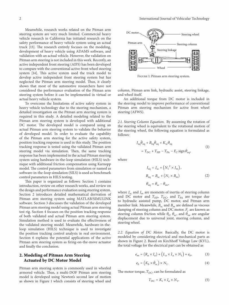
Pitman arm steering system is commonly used in wheeledarmored vehicle Thus a multi-DOF Pitman arm steeringmodel is developed using Newtonrsquos second law of motionas shown in Figure 1 which consists of steering wheel and
Steering wheel
Steering columnPitman arm
Steering linkage
Wheel
DC motor
Figure 1 Pitman arm steering system
column Pitman arm link hydraulic assist steering linkageand wheel itself
An additional torque from DC motor is included inthe steering model to improve performance of conventionalPitman arm steering mechanism for active front wheelsteering (AFWS)
21 Steering Column Equation By assuming the rotation ofthe steering wheel is equivalent to the rotational motion ofthe steering wheel the following equation is formulated asfollows
119869eqeq + 119861eqeq + 119870sc120579eq
= 119879DC + 119879HP minus 119879PA minus 119865119862 sign eq(1)
where
119869eq = 119869sc + (11987312times 119869119898)
119861eq = 119861sc + (1198731 times 119861119898)
120579eq = 120579sc minus 120579sw
(2)
where 119869sc and 119869119898 are moments of inertia of steering columnand DC motor and 119879HP 119879DC and 119879PA are torque dueto hydraulic assisted pump DC motor and Pitman armmember link Meanwhile 119861sc and 119861119898 are defined as viscousdamping of steering column and DC motor 119865
119888are known as
steering column friction while 120579119896 120579sc and 120579sw are angular
displacement due to universal joint steering column andsteering wheel
22 Equation of DC Motor Basically the DC motor ismodeled by considering electrical and mechanical parts asshown in Figure 2 Based on Kirchhoff Voltage Law (KVL)the total voltage for the electrical part can be obtained as
119890119898 = (119877119886 times 119868119886) + (119871119886 times 119886 times 1198731) + 119890119887 (3)
119890119887= (119870119887times sc) times 1198731 (4)
The motor torque 119879DC can be formulated as
119879DC = 119870119905 times 119868119886 times 1198731 (5)
International Journal of Vehicular Technology 3
DC motor
RaLa
Iaeb N1
TDCem
Figure 2 Electrical and mechanical model of DC motor
where 119890119898is the DC motor input voltage 119890
119887is back electro-
magnetic force and119877119886119871119886 and 119868
119886are the resistor inductance
and current flow of the DC motor The terms 119870119887and
119870119905are defined as back electromagnetic force and motor
torque constants and 1198731is defined as DC motor gear ratio
Rearrange expression (5) as a function of 119868119886as
119868119886 =
119879DC(119870119905times 1198731) (6)
By substituting expression (6) into (3) the final equation forDC motorrsquos torque can be obtained as
119879DC
=119870119905times 1198731
(119877119886)[119890119898minus (119870119887times sc times 1198731) + (119871119886 times 119886 times 1198731)]
(7)
where 119877119886is 01 ohm 119871
119886is 00001H119873
1is 16 3 gear ratio and
119870119887is 00533NsdotmA
23 Hydraulic Power Assisted Equation The other mech-anism connected to the steering column is the hydraulicpower assisted unitThis unit enables elimination of extensivemodifications to the existing steering system and reduceseffort by the driver to rotate the steering wheel since thehydraulic power assisted unit is able to produce large steeringeffort using hydraulic pump rotary spool valve and Pitmanarm
119879HP = 119897 times 119860119901 times int(119889119875119897
119889119905minus119889119875119903
119889119905) (8)
where 119875119903and 119875
119897are right and left cylinder pressures while
119897 is defined as length of cylinder and the piston area of thecylinder is expressed as 119860119901 The detailed description can beobtained from [15]
24 Universal Joint Equation Due to the limitation of spaceat the engine location of the armored vehicle the hydraulicpower assisted system cannot be located at the same axisas the steering wheel Hence an additional join known asuniversal joint is used as a solution to overcome the spaceconstraint The universal joint angle is used for the steeringmechanism since it is a flexible coupling where it is rigidin torsion but compliant in bending The angle of 0 is setat 20 degrees lower than the steering column 120579sc [16] anddescribed as
120579119896= tanminus1 (
tan 120579sccos 0
) (9)
Worm gear
Sector gear
Pitman arm Steering linkage
120579k
120591wg
120591sg
120591PA
Figure 3 System configuration using Pitman arm
25 Description on Pitman Arm The torque from thehydraulic power assisted model is transferred to actuate thePitman arm member link through the worm and sectorgears The Pitman arm converts the rotational motion ofthe steering column into translational motion at the steeringlinkage The configuration of worm gear sector gear andthe Pitman arm member is shown in Figure 3 Based onFigure 3 the output torque of the Pitman arm link 119879PA canbe obtained by equating both worm and sector gear torque119879wg and 119879sg as
119879sg = 120578sg times 119879wg = 120578sg times [119870tr (120579119896 minus 120579wg)] (10)
where ratio of sector gear is 120578sg and 120579wg is the angulardisplacement of worm gear Since the torque created at sectorgear is equal to the torque created at the end joint of Pitmanarm hence
119879sg = 119879PA (11)
26 Steering Linkage Equation The rotational input fromthe sector gear is converted into translational motion to thesteering linkage using Pitman arm joint link By using thetorque from Pitman arm as the input torque the equation ofmotion of the steering linkage is [17]
119872119871119871+ 119861119871119871+ [119862SL sgn (119871)] minus [
119887119903 times 119879PA119872119871times 119877PA
]
= 120578119891(119879PA119877PA) minus 120578119861(119879KL119873119872)
(12)
where 119872119871 119861119871 and 119862SL are mass viscous damping andcoulomb friction breakout force of steering linkage Addi-tionally the terms 119910
119871 119887119903 and 119877PA are the translational
displacement resistance at steering linkage and radius ofPitman arm 120578
119891and 120578119861are the gear ratio efficiency of forward
and backward transmission
4 International Journal of Vehicular Technology
Steering linkage
Wheel dynamics
Pitman arm
torque
DC motor model
Universal joint
Steering columnSteering
wheel
Human input
Hydraulic assisted power
Pacejka tire model
Heavy vehicle system
Pitman arm steering TDC
120579kinput 120579sw
120579swTDCTHP
THP
TPA
TPA
Ta
120575fyL
120579sc
Figure 4 Overall configuration of Pitman arm steering system using electronically actuated DC motor
27 Wheel Dynamics Equation By using (1) (7) (8) and (11)equation of motion of the wheel can be obtained The outputresponse of the wheel which is wheel angle 120575119891 is given by
119869fw119891 + 119861fw119891 + [119862fw sign (119891)] + 119870fw120575119891
= 119879KL + 119879119886
119879KL = 119870SL ((119910119871
119873119872
) minus 120575119891)
(13)
where 119869fw 119861fw and 119862fw are the moment of inertia ofroad wheel and rotation mass about steering displacementviscous damping of steering linkage bushing and coulombfriction breakout force on road wheel 119879
119886and 119879KL are the
tire alignment moment from Pacejka Magic Tire model andtorque at steering linkage 119873
119872 119870fw and 119870SL are rotational
ratio of steering linkage steering wheel stiffness and steeringtranslational stiffness due to linkage and bushing Figure 4shows overall configuration of the Pitman arm steeringactuated by DC motor
The state space equation is developed to summarize thefinal equations of the Pitman arm steering system as shownbelow
For steering column
1199021 = 120579eq
1199022= eq
1= eq = 1199022
2= eq =
1
119869eq[sum119879sc minus (119861eq + 119865119888sgn) eq minus 119870sc120579eq]
q = Aq + B119906
119860 =[[[
[
0 1
minus(119861eq + 119865119888sign)
119869eqminus119870sc119869eq
]]]
]
119861 =[[
[
0
sum119879sc119869eq
]]
]
(14)
where sum119879sc = 119879DC + 119879HP minus 119879PAFor steering linkage
1199023= 119910119871
1199024= 119871
3= 119871= 1199024
4= 119871=1
119872119871[minus (119861
119871+ 119862SLsgn) 119871
minus (119887119903 times 119879PA119872119871times 119877PA
) 120578119861(119870SL ((1119873119872) minus 120575119891)
119873119872
)119910119871
+ 120578119891(119879PA119877PA)]
q = Cq +D119906
119862 =[[[
[
0 1
minus(119861119871 + 119862SLsgn119872119871
) 120578119861(119870SL ((1119873119872) minus 120575119891)
119873119872times119872119871
)
]]]
]
119863 =[[
[
0
minus1
119872119871[(119887119903times 119879PA
119872119871 times 119877PA) + 120578119891(119879PA119877PA)]
]]
]
(15)
International Journal of Vehicular Technology 5
Steering wheel
Steering column
Control board
Gear box
(a) Top part of Pitman arm steering test rig
DC motorWheel Hydraulic unit
Rotary encoder
ECU
Microcontroller
Optocoupler
H-Bridge
(b) Bottom part of the Pitman arm steering test rig
Figure 5 Pitman arm test rig with ECU control system for HILS [18]
For wheel dynamic
1199025= 120575119891
1199026= 119891
5= 119891 = 1199026
2= 119871
=1
119869fw[sum119879fw minus (119861fw + 119862fwsgn) 119891 + 119870fw120575119891]
q = Eq + F119906
119864 =[[
[
0 1
minus (119861fw + 119862fwsgn)119869fw
119870fw119869fw
]]
]
119865 =[[
[
0
sum119879fw119869fw
]]
]
(16)
3 Validation of Pitman Arm Steering Model
In this section the behavior of Pitman arm steering modelis validated with actual Pitman arm steering system by usinghardware-in-the-loop (HIL) technique The purpose of thisvalidation is to analyze the performance of mathematicalmodel of Pitman arm steering model which is used in heavyvehicle such as truck bus or wheeled military vehicle Theparameters of the Pitman arm steering model are listed inTable 1The performance of themodel is validated using threetypes of lateral inputs such as double lane change slalom andstep steer test A detailed discussion on the performance ofthe Pitman arm steering model is discussed in this section
31 Hardware Setup A Pitman arm steering test rig hasbeen prepared in Automotive Laboratory at National DefenseUniversity of Malaysia (NDUM) as shown in Figure 5 Twoincremental rotary encoders are installed at the steeringcolumn and wheel chamber Meanwhile a DC motor hasbeen attached to the steering column to provide steeringinputs as initiated from the host PC An ECU as shown in
Target PC
Host PC
PCI DAQ 6221
ECU
External power source
Figure 6 Hardware-in-the-loop setup
Figure 4 has been designed to operate the DC motor usinghardware-in-the-loop (HIL) simulation [18 19]
32 Hardware-in-the-Loop Setup HIL technique is used inthis study to validate the developed mathematical model ofPitman arm steeringmodel with the actual Pitman arm steer-ing mechanism and to evaluate the performance of the Pit-man arm steering by providing various wheel inputs HIL canbe divided into two systemswhich are software and hardwareSoftware part includes signal interface betweenTarget PC andHOST PC xPC Target and Real-TimeWorkshop software tocontrol DC motor and measure the signal of rotary encoderwhile Visual Studio 2012 Express used as a C compiler forxPC Target MATLABSIMULINK software has been usedas interface to interlink between the hardware and HOSTPC via xPC Target As for the hardware section it involveswith the HOST PC Target PC Gear box of DC motor DCmotor Pitman arm steering test rig rotary encoders PCInetwork card anddata acquisition system known asNationalInstrument (NI) board The configuration of hardware canbe observed in Figures 5 and 6 as shown below With ahost computer running xPC Target MATLABSIMULINKReal-Time Workshop and a C compiler as the developmentenvironment real-time Pitman arm characteristic can begenerated and run on a Target PC using the xPC Target real-time kernel After the Target PC is interlinked with hardwarethe Pitman arm steering can be simulated in real time [18]
33 Validation Results Four types of steering inputs havebeen used to validate the Pitman arm steering model Theinputs are known as double lane change and slalom test at
6 International Journal of Vehicular Technology
Table 1 Parameter of the Pitman arm steering model
Description Symbol ValueMoment of inertia of steering wheel 119869sw 0035 kgm2
Viscous damping of steering wheel 119861sw 036Nm(radsec)Steering column rotational stiffness 119870sc 42000NmradAngular displacement due to universal joint 120579
11989620∘
Steering arm length 119897119904
02mReturn pressure 119875
1199000Nm2
Pump flow rate 119876119904
00002m3sPiston area 119860
1199010005m2
Cylinder length L 015mOrifice flow coefficient 119862do 06Fluid density 120588 825 kgm3
Fluid volume 119881119904
82 times 10minus5m3
Fluid bulk modulus 120573119891
75 times 108Nm2
Torsion bar rotational stiffness 119870tr 35000NmradSector gear ratio 120591sg 05Moment of inertia of steering column 119869sc 0055 kgm2
Viscous damping of steering column 119861sc 026Nm(radsec)Coulomb friction breakout force on steering linkage 119862SL 05NGear ratio efficiency of forward transmission 120578
1198910985
Gear ratio efficiency of backward transmission 120578119861
0985Steering rotational stiffness due to linkage and bushing 119870SL 15500NmradMetering orifice 119860
1and 119860
225mm2
Whe
el an
gle (
deg
)
Wheel angle against time
ActualSimulation
minus6
minus4
minus2
0
2
4
05 1 15 2 25 30Time t
Figure 7 Wheel angle for double lane change case
90 degrees as well as step steer at 90 and 180 degrees Thevalidation results are presented in Figures 7ndash10 which arethe comparison between the measured the wheel angle andalso the wheel angle from the simulated Pitman arm steeringmodel based on the actual steering inputs Based on thevalidation results it can be concluded that the mathematicalmodel of Pitman arm steering actuated byDCmotormodel isable to follow the desired response which was obtained fromactual steering responses
In order to analyze the performance of the developedPitman arm model the maximum error between actual and
Whe
el an
gle (
deg
)
ActualSimulation
Wheel angle against time
minus5
0
5
2 4 6 8 100Time t
Figure 8 Wheel angle for slalom case
simulation results and root mean square (RMS) is analyzedin this study The maximum error for double lane changeand slalom test is 235 and 181Meanwhile themaximumerrors for step steer test at both 90 and 180 degrees are323 and 307 The maximum error range is less than 5Similarly the percentages of RMS value for both simulationand actual Pitman arm steeringmodel are comparedTheper-centages of differences using RMS value between simulatedand actual system are not more than 2 as shown in Table 2
International Journal of Vehicular Technology 7W
heel
angl
e (ra
d)
ActualSimulation
Wheel angle against time at 90 deg
0
1
2
3
4
5
1 2 3 4 50Time t
Figure 9 Wheel angle of step steer case at 90-degree steering angle
Whe
el an
gle (
deg
)
ActualSimulation
Wheel angle against time at 180 deg
0
2
4
6
8
10
1 2 3 4 50Time t
Figure 10 Wheel angle of step steer case at 180-degree steeringangle
Table 2 Percentage value of RMS difference
Test RMS Percentage difference ()Actual Sim
Double lane change 0331 0325 169Slalom 000253 000257 143Step steer at 90 deg 00715 00719 061Step steer at 180 deg 00772 00778 078
4 Hardware-in-the-Loop Simulation ofPitman Arm Steering System
Before implementing steering mechanism into active safetysystem of a vehicle such as steer-by-wire active front wheelsteering and electronic stability control the mechanismshould be tested using hardware-in-the-loop simulation(HILS) technique HILS testing or commonly known asvirtual testing electronic control has also become one of therepository tools for the automotive researchers and designersHILS technique is required in testing an actuator to identifyits capability and performance before it can be applied to anyreal automotive system
In this study bothmathematicalmodel and actual Pitmanarm steering are tested using various wheel inputsThemath-ematicalmodel is tested via simulation known as software-in-the-loop simulation (SILS) analysis by tuning the controllerparameters to its optimum value which can be used forvarious inputs The parameters of PID controller are tunedby using the Ziegler-Nichols technique The Ziegler-Nicholstuning method attempts to produce optimum values for thePID gain parameters [20 21] The similar control parametersare implemented while testing the actual pitman arm steeringmechanism using HILS technique
Two types of control loops are mainly focused in positiontracking control of the pitman arm steering mechanismwhich are inner and outer loop control The inner loopcontrol is focused on the position control of a DC motor forboth simulation and HILS technique which can be referredfrom [19] Meanwhile the outer loop control is designed byusing the Pitman arm steering model for simulation analysisand actual mechanisms for HIL analysis A conventional PIDcontrol is used as the controller for both inner and outer loopcontrols
41 Position Tracking Control The position tracking controlis developed by merging both inner and outer loop controlsas shown in Figure 11 Two PID controllers have been usedto control the DC motor shaftrsquos rotational angle and alsothe steering column of the Pitman arm steering system Thefirst PID controller is used to command the DC motor byvarying the voltage input to the DC motor Meanwhile thesecond PID controller is used to actuate the steering columnaccording to the desired inputs Therefore the validatedPitman arm steering model is used initially to evaluateposition tracking control using a PID controller via SILSanalysisThe control structure of the position tracking controlis developed as shown in Figure 11
Meanwhile Figure 12 shows the control structure forposition tracking control of the Pitman arm steering modelusing an automotive DC motor Two rotary sensors havebeen used to measure the rotation angle of the DC motorwhich is attached to the steering column Meanwhile theother rotary sensor is mounted at the wheel tomeasure actualwheel angle The output signal from first PID controller issent as analogue output to the DC motor using the PCI 6221National Instrument (DA) The signals obtained from rotarysensors which are connected through PCI 6221 NationalInstrument (DA) are used as feedback input to the HILSevaluation Likewise the position tracking of the Pitmanarm steering system is validated using four different typesof inputs namely sine square sawtooth and step inputsSimilar PID control parameters from SILS are used for theHILS experiment as the benchmark point However there areslight changes in the control parameters due to the frictionalforce that occurred on the Pitman armmember link and alsobacklash occurred at the gear mechanismwhich connects theDC motor and the steering column The control parametersare listed in Table 3 for further references
In the HILS results there are some disturbances thatoccurred due to the mechanical friction which affects theperformance of the Pitman arm steering system In order to
8 International Journal of Vehicular Technology
Wheel angle
Desired input
PID 2 PID 1 DC motor
Pitman arm steering
Error
Inner loop
Actual wheel outputShaft angle Voltage
Steering angle
+ +
minus minus
Figure 11 Position tracking control using validated steering model for SILS
Wheel angle
Desired input
PID 2 PID 1
Actual wheel output
Shaft angle connected to pitman steering column
++
Friction estimation and compensation
Velocity
PI
Velocity(Sensed estimated or desired)Friction
compensation
minus
minus
k2
Figure 12 Position tracking control using actual Pitman arm steering for HILS
Table 3 Controller parameters for inner and outer loop
Technique Inner loop Outer loopP I D P I D
SILS 95 001 27 33 27 003HILS 15 001 6 40 015 003
minimize the effect a model-based compensation approachis used in this study Its implementation requires choice of anappropriate friction model identification of its parametersand finally friction compensation using the identified modelBesides this model also assumes that the frictional force ortorque of adequate bandwidth is available and stiffly coupledto the friction element Therefore friction compensation isimplemented by adding the opposite of the predicted frictionto the control signal as shown in Figure 15 To cope with thepresence of actuator dynamics one possibility is to use aninner force control loop in addition to the position controlloop The HILS control structure with implementation offriction compensation can beminimized position steady stateerror and oscillation generated by unwanted friction In thispaper the diagram in Figure 14 is used for Karnopp model-based friction compensation in the electric DC motor andPitman steering system Model-based friction compensationusing the Karnopp model in an electric-motor system hasbeen already used [22] This compensator gives satisfactoryresults when the objective is position tracking response
The Karnopp model solves the unwanted friction prob-lem by introducing a pseudo velocity a small neighbourhoodof zero velocity 119863V The pseudo velocity 119901(119905) which isreferred from momentum is integrated in the standard way
(119905) = [119865119886 (119905) minus 119865119898 (119905)] (17)
where119865119886(119905) is the force acting on the systemwhile119865
119898(119905) is the
estimated friction force based on the system response Thevelocity of the system is set according to (17) where 119872fc isreferred to as steering mass
V (119905) =
01003816100381610038161003816119901 (119905)
1003816100381610038161003816 lt 119863V
1
119872119901 (119905)
1003816100381610038161003816119901 (119905)1003816100381610038161003816 ge 119863V
(18)
The friction law is described as follows
119865119898 (V (119905) 119865119886 (119905))
=
minus sgn [119865119886 (119905)]max [1003816100381610038161003816119865119886 (119905)
1003816100381610038161003816 (119865119888 + 119865119904)] |V (119905)| lt 119863V
minus sgn [V (119905)] 119865119888 + 119865VV (119905) |V (119905)| ge 119863V
(19)
where (19) includes static coulomb and viscous terms 119865119904 119865119888
and 119865V
42 Performance Evaluation In this study both SILS andHILSwere performed for a period of 10 seconds using Runge-Kutta solver with a fixed step size of 0001 secondsThemodelis evaluated with various inputs with two types of frequencywhich are 05 and 10 hertz The purpose of this validation isto verify the capability of the pitman arm steering to followdesired steering correction response after implementationin heavy vehicle system Four types of desired trajectoriesknown as sine square sawtooth and step inputs have beenused to verify the performance of the actual and the validatedmodel pitman arm steering as shown in Figures 13ndash21
Figures 13 and 14 show the comparison of the desired sineinput wheel angle compared with the SILS and HILS resultswith and without friction compensation Both SILS andHILSresults are able to follow the desired wheel angle HILS with
International Journal of Vehicular Technology 9
minus4
minus2
0
2
4
6Wheel angle against time using sine input
SILSHILS with FC
TargetHILS without FC
Whe
el an
gle (
deg
)
2 4 6 8 100Time t
Figure 13 Wheel angle using sine input at 05 hz
Wheel angle against time using sine input
minus4
minus2
0
2
4
6
Whe
el an
gle (
deg
)
2 4 6 8 100Time t
SILSHILS with FC
TargetHILS without FC
Figure 14 Wheel angle using sine input at 10 hz
friction compensation follow the response without any influ-ence from hardware but HILS without friction compensationfollow the desired response with minor phase shifting dueto mechanical response after experiencing friction betweengears It shows that friction compensation able to minimizethe effect of the frictional force occurred in the hardwareTheresponses of the wheel angle for square inputs are shown inFigures 15 and 16 which illustrateminor deviation usingHILSwithout friction compensation compared with simulationand HILS with friction compensation results There is over-shoot that occurred at each change point due to the backlashbetween gears of the DC motors This interaction causesdelay time up to 04 seconds as observed in the HILS resultsBy implementing the frictional compensation model theovershoot in square response has been reduced significantlyBesides the dead time that occurred during phase change hasbeenminimized greatly comparedwithHILSwithout frictioncompensation response Meanwhile Figures 17 and 18 showthe wheel angle using sawtooth inputs The results showdeviation during the middle of each period This deviationmainly caused by the hardware interaction causes frictionbetween connections of the pitman arm steering system andsteering column which is attached to the hydraulic assistunit [19] However these minor deviations can be reducedby adding the friction compensation which estimated the
Wheel angle against time using square input
Whe
el an
gle (
deg
)
minus6
minus4
minus2
0
2
4
6
2 4 6 8 100Time t
SILSHILS with FC
TargetHILS without FC
Figure 15 Wheel angle using square input at 05 hz
Wheel angle against time using square input
Whe
el an
gle (
deg
)
2 4 6 8 100Time t
minus6
minus4
minus2
0
2
4
6
SILSHILS with FC
TargetHILS without FC
Figure 16 Wheel angle using square input at 10 hz
friction that occurred andminimized the effects of unwantedfriction
Figures 19 and 20 represent the step response for HILSand SILS position tracking control using two desired wheelangles of 45∘ and 9∘ The HILS with friction compensationresults show that the rise-time of step input of wheel angleat 45∘ and 9∘ is 307 s and 305 s at 10 height and at 90of height is 345 s and 348 s while dead time occurs upto 008 s from rest condition in both cases The maximumpercentage of overshoot is up to 113 for wheel angle of 45∘and 102 for wheel angle of 9∘ as shown in Figures 19 and20 This minor deviation occurred due to sudden change inrotary sensors response and also because mechanical frictionhappened between the mounting and gear mechanism whichconnects DCmotor and steering column However the HILSperformance has been improved significantly by adding thefriction compensation model in the HILS control structurewhich can be observed in Figures 19 and 20 Overallthe response of position tracking response of Pitman armsteering using automotive DC motor shows good agreementbetween desired trajectories simulation and actual responsefrom validated and actual Pitman arm steering since theresponse of the actual response follows the desired input witha delay of less than 1 s
10 International Journal of Vehicular Technology
Wheel angle against time using sawtooth input
Whe
el an
gle (
deg
)
2 4 6 8 100Time t
minus6
minus4
minus2
0
2
4
6
SILSHILS with FC
TargetHILS without FC
Figure 17 Wheel angle using sawtooth input at 05 hertz
Wheel angle against time using sawtooth input
Whe
el an
gle (
deg
)
2 4 6 8 100Time t
minus5
0
5
SILSHILS with FC
TargetHILS without FC
Figure 18 Wheel angle using sawtooth input at 10 hertz
5 Future Works
Currently this Pitman arm steering model is used as afiring-on-the-move actuator (FOMA) in the armored vehi-cle model This active system is used mainly to rejectthe unwanted external disturbance due to backward firingmomentum from the gun turret The dynamic performanceof the vehicle model with the pitman arm actuator systemis analyzed in terms of yaw rate lateral acceleration andalso vehicle body side slip An advance control strategyis proposed to enhance the dynamic performance of thearmored vehicle in terms of the directional path and stabilityof the armored vehicle after firing The configuration ofFOMA in armored vehicle is shown in Figure 21
6 Conclusions
In this study the Pitman arm steering system is developedusing Newtonrsquos law motion to describe the working principleof the steering system The Pitman arm steering model isthen validated with an actual Pitman arm steering systemin order to validate the mathematical model of the Pitman
Wheel angle against time using step input
SILSHILS with FC
TargetHILS without FC
Whe
el an
gle (
deg
)
1 2 3 4 5 60Time t
minus1
0
1
2
3
4
5
Figure 19 Wheel angle using step input response at 45 degree
Wheel angle against time using step input
SILSHILS with FC
TargetHILS without FC
Whe
el an
gle (
deg
)
0
2
4
6
8
10
1 2 3 4 5 60Time t
Figure 20 Wheel angle using step input response at 9 degree
arm steering model Four types of steering inputs in thelateral direction are used to evaluate the behavior of the devel-oped steering model Then position tracking system usingsoftware-in-the-loop simulation (SILS) and hardware-in-the-loop simulation (HILS) is developed using both validated andactual pitman arm steering system Various types of desiredinputs have been used to evaluate the performance of thevalidated and actual pitman arm steering system In order toimprove the HILS performance friction compensation usingKarnopp model is implemented in this study to minimizethe effect of mechanical friction on the system Significantimprovement is obtained for the HILS results which isable to follow the desired response with errors less than10 The position tracking system improved with frictioncompensation is used as inner loopmodel in the developmentof an active safety system in armored vehicle
Competing Interests
The authors declare that there are no competing interestsregarding the publication of this paper
International Journal of Vehicular Technology 11
12 3
4
5
6
7Input
CoG
10
8 9
11
2
12
13
14
15
16
17
18
Output
(1) Gun turret(2) Rotary encoder(3) Force sensor(4) 12V battery(5) DC-AC converter(6) Integrated PC based module(7) Integrated DAQ(8) Microcontroller(9) Motor current driver
(10) Gyro sensor
(18) Steering
(11) Brushless DC motor(12) Touch screen LCD(13) Pitman arm(14) Hydraulic power assist(15) Wheel speed sensor(16) Vehicle body(17) Wheel
(a) Side view of armored vehicle
Gun turret rotation
CoG
Cross sectionview
1 3
2
4 57
InputsInputs O
utpu
t
6
10
8
9
11
12 14
192
13
18 16
15
17
(1) Gun turret(2) Rotary encoder(3) Force sensor(4) 12V battery(5) DC-AC converter(6) Integrated PC based module(7) Integrated DAQ(8) Microcontroller(9) Motor current driver
(10) Gyro sensor (19) Steering(11) Brushless DC motor(12) Touch screen LCD(13) Pitman arm(14) Hydraulic power assist(15) Wheel speed sensor(16) Vehicle body(17) Wheel(18) Knuckle
(b) Top view of armored vehicle
Figure 21 System configuration of electronically actuated Pitman arm steering system as firing-on-the-move actuator [23]
12 International Journal of Vehicular Technology
Acknowledgments
This work is part of a research project entitled ldquoRobust Sta-bilization of Armored Vehicle Firing Dynamic Using ActiveFront Wheel Steering Systemrdquo funded by LRGS Grant (noLRGSB-U2013UPNMDEFENSE and SECURITY-P1) andled byAssociate ProfessorDr KhisbullahHudhaThe authorswould like to thank the Malaysian Ministry of ScienceTechnology and Innovation (MOSTI) MyPhD programmefromMinister of Education and National Defense Universityof Malaysia (NDUM) for their continuous support and thesupport is gratefully acknowledged
References
[1] Z Li and W Wenjiang ldquoStudy on stability of electric powersteering systemrdquo in Proceedings of the IEEE International Con-ference on Robotics Automation and Mechatronics (RAM rsquo08)pp 368ndash372 IEEE Chengdu China September 2008
[2] A Marouf C Sentouh M Djemai and P Pudlo ldquoControl of anelectric power assisted steering system using reference modelrdquoin Proceedings of the 50th IEEE Conference on Decision andControl and European Control Conference (CDC-ECC rsquo11) pp6684ndash6690 IEEE Orlando Fla USA December 2011
[3] L Dong K Prasanth G Zhiqiang and W Dexin ldquoActive dis-turbance rejection control for an electric power assist steeringsystemrdquo International Journal of Intelligent Control and Systemvol 15 no 1 pp 18ndash24 2010
[4] P Koehn andM Eckrich ldquoActive steeringmdashthe BMWapproachtowards modern steering technologyrdquo SAE Technical Paper2004-01-1105 2004
[5] W Oraby S El-Demerdash A Selim A Faizz and D ACrolla ldquoImprovement of vehicle lateral dynamics by activefront steering controlrdquo SAE Technical Paper 2004-01-2081 SAEInternational 2004
[6] L Dong P Kandula Z Gao and D Wang ldquoActive disturbancerejection control for an electric power assist steering systemrdquoInternational Journal of Intelligent Control and System vol 15pp 18ndash24 2010
[7] T Kojo M Suzumura Y Tsuchiya and Y Hattori ldquoDevelop-ment of active front steering control systemrdquo SAE TechnicalPaper 2005-01-0404 2005
[8] Y Yao ldquoVehicle steer-by-wire system controlrdquo SAE TechnicalPaper 2006-01-1175 SAE International 2006
[9] Y Yao and B Daugherty ldquoControl method of dual motor-basedsteer-by-wire systemrdquo SAE Technical Paper 2007-01-1149 SAEInternational 2007
[10] J Li J Feng and F Yu ldquoStudy of vehicle yaw stability controlbased on hardware-in-the-loop simulationrdquo SAE TechnicalPaper 2005-01-1845 SAE International 2005
[11] K Hudha M H Zakaria and N Tamaldin ldquoHardware in theloop simulation of active front wheel steering control for yawdisturbance rejectionrdquo International Journal of Vehicle Safetyvol 5 no 4 pp 356ndash373 2011
[12] H Schuette and P Waeltermann ldquoHardware-in-the-loop test-ing of vehicle dynamics controllersmdasha technical surveyrdquo SAETechnical Paper 2005-01-1660 2005
[13] J C Gerdes P Yih and K Satyan Safety Performance andRobustness of Heavy Vehicle AVCS California PATH Program2002
[14] A Farazandeh A K W Ahmed and S Rakheja ldquoPerformanceAnalysis of Active Independent Front Steering (AIFS) forcommercial vehicles with greater lateral load shift propensityrdquoSAE International Journal of Commercial Vehicles vol 6 no 2pp 288ndash300 2013
[15] V R Aparow K Hudha M M Hamdan and S AbdullahldquoStudy on dynamic performance of armoured vehicle in lateraldirection due to firing impactrdquo Journal of Advances in MilitaryTechnology vol 10 no 2 pp 5ndash20 2015
[16] D Karnopp R Argolis and R Rosenberg System DynamisModeling and Simulations of Mechatronic Systems John Wileyamp Sons New York NY USA 2000
[17] G N Shwetha H R Ramesh and S R Shankapal ldquoModelingsimulation and implementation of a proportional-derivativecontrolled column-type EPSrdquo International Journal of EnhancedResearch in Science Technology and Engineering vol 2 no 9 pp10ndash19 2013
[18] V R Aparow K Hudha F Ahmad and H JamaluddinldquoModeling and validation of electronic wedge brakemechanismfor vehicle safety systemrdquo Jurnal Teknologi vol 75 no 1 pp 183ndash191 2015
[19] V R AparowKHudha F Ahmad andH Jamaluddin ldquoModel-in-the-loop simulation of gap and torque tracking control usingelectronicwedge brake actuatorrdquo International Journal of VehicleSafety vol 7 no 3-4 pp 390ndash408 2014
[20] M S Saad H Jamaluddin and I ZMDarus ldquoImplementationof PID controller tuning using differential evolution and geneticalgorithmsrdquo International Journal of Innovative ComputingInformation and Control vol 8 no 11 pp 7761ndash7779 2012
[21] P M Meshram and R G Kanojiya ldquoTuning of PID controllerusing Ziegler-Nichols method for speed control of DC motorrdquoin Proceedings of the 1st International Conference on Advancesin Engineering Science andManagement (ICAESM rsquo12) pp 117ndash122 Tamil Nadu India March 2012
[22] A Voda and L Ravanbod-Shirazi ldquoHigh performance positiontracking with friction compensation for an electro-pneumaticalactuatorrdquo Journal of Control Engineering and Applied Informat-ics vol 6 no 2 pp 15ndash33 2004
[23] K Hudha V R Aparow M Murad et al ldquoYaw stability controlsystemrdquo Malaysian Patent PI 2015700778 October 2014
International Journal of
AerospaceEngineeringHindawi Publishing Corporationhttpwwwhindawicom Volume 2014
RoboticsJournal of
Hindawi Publishing Corporationhttpwwwhindawicom Volume 2014
Hindawi Publishing Corporationhttpwwwhindawicom Volume 2014
Active and Passive Electronic Components
Control Scienceand Engineering
Journal of
Hindawi Publishing Corporationhttpwwwhindawicom Volume 2014
International Journal of
RotatingMachinery
Hindawi Publishing Corporationhttpwwwhindawicom Volume 2014
Hindawi Publishing Corporation httpwwwhindawicom
Journal ofEngineeringVolume 2014
Submit your manuscripts athttpwwwhindawicom
VLSI Design
Hindawi Publishing Corporationhttpwwwhindawicom Volume 2014
Hindawi Publishing Corporationhttpwwwhindawicom Volume 2014
Shock and Vibration
Hindawi Publishing Corporationhttpwwwhindawicom Volume 2014
Civil EngineeringAdvances in
Acoustics and VibrationAdvances in
Hindawi Publishing Corporationhttpwwwhindawicom Volume 2014
Hindawi Publishing Corporationhttpwwwhindawicom Volume 2014
Electrical and Computer Engineering
Journal of
Advances inOptoElectronics
Hindawi Publishing Corporation httpwwwhindawicom
Volume 2014
The Scientific World JournalHindawi Publishing Corporation httpwwwhindawicom Volume 2014
SensorsJournal of
Hindawi Publishing Corporationhttpwwwhindawicom Volume 2014
Modelling amp Simulation in EngineeringHindawi Publishing Corporation httpwwwhindawicom Volume 2014
Hindawi Publishing Corporationhttpwwwhindawicom Volume 2014
Chemical EngineeringInternational Journal of Antennas and
Propagation
International Journal of
Hindawi Publishing Corporationhttpwwwhindawicom Volume 2014
Hindawi Publishing Corporationhttpwwwhindawicom Volume 2014
Navigation and Observation
International Journal of
Hindawi Publishing Corporationhttpwwwhindawicom Volume 2014
DistributedSensor Networks
International Journal of
2 International Journal of Vehicular Technology
Meanwhile research works related on the Pitman armsteering system are very much limited Commercial heavyvehicle research in California has initiated research on thesafety performance of heavy vehicle system using an actualtruck [13] The research entirely focuses on the modelingdevelopment of heavy vehicle using ADAMS software andvalidation with an actual vehicle However the validation onPitman arm steering is not included in this work Recently anactive independent front steering (AIFS) has been developedto compare with the conventional active front wheel steeringsystem [14] This active system used the truck model todevelop active independent front steering system but hasneglected the Pitman arm steering model Thus it clearlyshows that most of the automotive researchers have notconsidered the performance evaluation of the Pitman armsteering system before it can be implemented in virtual oractual heavy vehicle system
To overcome the limitations of active safety system inheavy vehicle technology due to the steering mechanism adetailed investigation on the Pitman arm steering system isrequired in this study A detailed modeling related to thePitman arm steering system is developed with additionalDC motor The developed model is compared using anactual Pitman arm steering system to validate the behaviorof developed model In order to evaluate the capabilityof the Pitman arm steering for the active safety systemposition tracking response is used in this study The positiontracking response is tested using the validated Pitman armsteering model via simulation Then the same trackingresponse has been implemented in the actual Pitman steeringsystem using hardware-in-the-loop simulation (HILS) tech-nique with additional friction compensation using Karnoppmodel The control parameters from simulation or named assoftware-in-the-loop simulation (SILS) is used as benchmarkcontrol parameters in HILS testing
This paper is organized as follows Section 1 containsintroduction review on other research works and review onthe design and performance evaluation using steering systemSection 2 introduces detailed mathematical derivation ofPitman arm steering system using MATLABSIMULINKsoftware Section 3 discusses the validation of the developedPitman arm steering model using actual Pitman arm steeringtest rig Section 4 focuses on the position tracking responseof both validated and actual Pitman arm steering systemSimulation method is used to evaluate the effectiveness ofthe validated steering model Meanwhile hardware-in-the-loop simulation (HILS) technique is used to investigatethe position tracking control analysis in real environmentSection 6 explains the potential applications of the activePitman arm steering system as firing-on-the-move actuatorand finally the conclusion
2 Modeling of Pitman Arm SteeringActuated by DC Motor Model
Pitman arm steering system is commonly used in wheeledarmored vehicle Thus a multi-DOF Pitman arm steeringmodel is developed using Newtonrsquos second law of motionas shown in Figure 1 which consists of steering wheel and
Steering wheel
Steering columnPitman arm
Steering linkage
Wheel
DC motor
Figure 1 Pitman arm steering system
column Pitman arm link hydraulic assist steering linkageand wheel itself
An additional torque from DC motor is included inthe steering model to improve performance of conventionalPitman arm steering mechanism for active front wheelsteering (AFWS)
21 Steering Column Equation By assuming the rotation ofthe steering wheel is equivalent to the rotational motion ofthe steering wheel the following equation is formulated asfollows
119869eqeq + 119861eqeq + 119870sc120579eq
= 119879DC + 119879HP minus 119879PA minus 119865119862 sign eq(1)
where
119869eq = 119869sc + (11987312times 119869119898)
119861eq = 119861sc + (1198731 times 119861119898)
120579eq = 120579sc minus 120579sw
(2)
where 119869sc and 119869119898 are moments of inertia of steering columnand DC motor and 119879HP 119879DC and 119879PA are torque dueto hydraulic assisted pump DC motor and Pitman armmember link Meanwhile 119861sc and 119861119898 are defined as viscousdamping of steering column and DC motor 119865
119888are known as
steering column friction while 120579119896 120579sc and 120579sw are angular
displacement due to universal joint steering column andsteering wheel
22 Equation of DC Motor Basically the DC motor ismodeled by considering electrical and mechanical parts asshown in Figure 2 Based on Kirchhoff Voltage Law (KVL)the total voltage for the electrical part can be obtained as
119890119898 = (119877119886 times 119868119886) + (119871119886 times 119886 times 1198731) + 119890119887 (3)
119890119887= (119870119887times sc) times 1198731 (4)
The motor torque 119879DC can be formulated as
119879DC = 119870119905 times 119868119886 times 1198731 (5)
International Journal of Vehicular Technology 3
DC motor
RaLa
Iaeb N1
TDCem
Figure 2 Electrical and mechanical model of DC motor
where 119890119898is the DC motor input voltage 119890
119887is back electro-
magnetic force and119877119886119871119886 and 119868
119886are the resistor inductance
and current flow of the DC motor The terms 119870119887and
119870119905are defined as back electromagnetic force and motor
torque constants and 1198731is defined as DC motor gear ratio
Rearrange expression (5) as a function of 119868119886as
119868119886 =
119879DC(119870119905times 1198731) (6)
By substituting expression (6) into (3) the final equation forDC motorrsquos torque can be obtained as
119879DC
=119870119905times 1198731
(119877119886)[119890119898minus (119870119887times sc times 1198731) + (119871119886 times 119886 times 1198731)]
(7)
where 119877119886is 01 ohm 119871
119886is 00001H119873
1is 16 3 gear ratio and
119870119887is 00533NsdotmA
23 Hydraulic Power Assisted Equation The other mech-anism connected to the steering column is the hydraulicpower assisted unitThis unit enables elimination of extensivemodifications to the existing steering system and reduceseffort by the driver to rotate the steering wheel since thehydraulic power assisted unit is able to produce large steeringeffort using hydraulic pump rotary spool valve and Pitmanarm
119879HP = 119897 times 119860119901 times int(119889119875119897
119889119905minus119889119875119903
119889119905) (8)
where 119875119903and 119875
119897are right and left cylinder pressures while
119897 is defined as length of cylinder and the piston area of thecylinder is expressed as 119860119901 The detailed description can beobtained from [15]
24 Universal Joint Equation Due to the limitation of spaceat the engine location of the armored vehicle the hydraulicpower assisted system cannot be located at the same axisas the steering wheel Hence an additional join known asuniversal joint is used as a solution to overcome the spaceconstraint The universal joint angle is used for the steeringmechanism since it is a flexible coupling where it is rigidin torsion but compliant in bending The angle of 0 is setat 20 degrees lower than the steering column 120579sc [16] anddescribed as
120579119896= tanminus1 (
tan 120579sccos 0
) (9)
Worm gear
Sector gear
Pitman arm Steering linkage
120579k
120591wg
120591sg
120591PA
Figure 3 System configuration using Pitman arm
25 Description on Pitman Arm The torque from thehydraulic power assisted model is transferred to actuate thePitman arm member link through the worm and sectorgears The Pitman arm converts the rotational motion ofthe steering column into translational motion at the steeringlinkage The configuration of worm gear sector gear andthe Pitman arm member is shown in Figure 3 Based onFigure 3 the output torque of the Pitman arm link 119879PA canbe obtained by equating both worm and sector gear torque119879wg and 119879sg as
119879sg = 120578sg times 119879wg = 120578sg times [119870tr (120579119896 minus 120579wg)] (10)
where ratio of sector gear is 120578sg and 120579wg is the angulardisplacement of worm gear Since the torque created at sectorgear is equal to the torque created at the end joint of Pitmanarm hence
119879sg = 119879PA (11)
26 Steering Linkage Equation The rotational input fromthe sector gear is converted into translational motion to thesteering linkage using Pitman arm joint link By using thetorque from Pitman arm as the input torque the equation ofmotion of the steering linkage is [17]
119872119871119871+ 119861119871119871+ [119862SL sgn (119871)] minus [
119887119903 times 119879PA119872119871times 119877PA
]
= 120578119891(119879PA119877PA) minus 120578119861(119879KL119873119872)
(12)
where 119872119871 119861119871 and 119862SL are mass viscous damping andcoulomb friction breakout force of steering linkage Addi-tionally the terms 119910
119871 119887119903 and 119877PA are the translational
displacement resistance at steering linkage and radius ofPitman arm 120578
119891and 120578119861are the gear ratio efficiency of forward
and backward transmission
4 International Journal of Vehicular Technology
Steering linkage
Wheel dynamics
Pitman arm
torque
DC motor model
Universal joint
Steering columnSteering
wheel
Human input
Hydraulic assisted power
Pacejka tire model
Heavy vehicle system
Pitman arm steering TDC
120579kinput 120579sw
120579swTDCTHP
THP
TPA
TPA
Ta
120575fyL
120579sc
Figure 4 Overall configuration of Pitman arm steering system using electronically actuated DC motor
27 Wheel Dynamics Equation By using (1) (7) (8) and (11)equation of motion of the wheel can be obtained The outputresponse of the wheel which is wheel angle 120575119891 is given by
119869fw119891 + 119861fw119891 + [119862fw sign (119891)] + 119870fw120575119891
= 119879KL + 119879119886
119879KL = 119870SL ((119910119871
119873119872
) minus 120575119891)
(13)
where 119869fw 119861fw and 119862fw are the moment of inertia ofroad wheel and rotation mass about steering displacementviscous damping of steering linkage bushing and coulombfriction breakout force on road wheel 119879
119886and 119879KL are the
tire alignment moment from Pacejka Magic Tire model andtorque at steering linkage 119873
119872 119870fw and 119870SL are rotational
ratio of steering linkage steering wheel stiffness and steeringtranslational stiffness due to linkage and bushing Figure 4shows overall configuration of the Pitman arm steeringactuated by DC motor
The state space equation is developed to summarize thefinal equations of the Pitman arm steering system as shownbelow
For steering column
1199021 = 120579eq
1199022= eq
1= eq = 1199022
2= eq =
1
119869eq[sum119879sc minus (119861eq + 119865119888sgn) eq minus 119870sc120579eq]
q = Aq + B119906
119860 =[[[
[
0 1
minus(119861eq + 119865119888sign)
119869eqminus119870sc119869eq
]]]
]
119861 =[[
[
0
sum119879sc119869eq
]]
]
(14)
where sum119879sc = 119879DC + 119879HP minus 119879PAFor steering linkage
1199023= 119910119871
1199024= 119871
3= 119871= 1199024
4= 119871=1
119872119871[minus (119861
119871+ 119862SLsgn) 119871
minus (119887119903 times 119879PA119872119871times 119877PA
) 120578119861(119870SL ((1119873119872) minus 120575119891)
119873119872
)119910119871
+ 120578119891(119879PA119877PA)]
q = Cq +D119906
119862 =[[[
[
0 1
minus(119861119871 + 119862SLsgn119872119871
) 120578119861(119870SL ((1119873119872) minus 120575119891)
119873119872times119872119871
)
]]]
]
119863 =[[
[
0
minus1
119872119871[(119887119903times 119879PA
119872119871 times 119877PA) + 120578119891(119879PA119877PA)]
]]
]
(15)
International Journal of Vehicular Technology 5
Steering wheel
Steering column
Control board
Gear box
(a) Top part of Pitman arm steering test rig
DC motorWheel Hydraulic unit
Rotary encoder
ECU
Microcontroller
Optocoupler
H-Bridge
(b) Bottom part of the Pitman arm steering test rig
Figure 5 Pitman arm test rig with ECU control system for HILS [18]
For wheel dynamic
1199025= 120575119891
1199026= 119891
5= 119891 = 1199026
2= 119871
=1
119869fw[sum119879fw minus (119861fw + 119862fwsgn) 119891 + 119870fw120575119891]
q = Eq + F119906
119864 =[[
[
0 1
minus (119861fw + 119862fwsgn)119869fw
119870fw119869fw
]]
]
119865 =[[
[
0
sum119879fw119869fw
]]
]
(16)
3 Validation of Pitman Arm Steering Model
In this section the behavior of Pitman arm steering modelis validated with actual Pitman arm steering system by usinghardware-in-the-loop (HIL) technique The purpose of thisvalidation is to analyze the performance of mathematicalmodel of Pitman arm steering model which is used in heavyvehicle such as truck bus or wheeled military vehicle Theparameters of the Pitman arm steering model are listed inTable 1The performance of themodel is validated using threetypes of lateral inputs such as double lane change slalom andstep steer test A detailed discussion on the performance ofthe Pitman arm steering model is discussed in this section
31 Hardware Setup A Pitman arm steering test rig hasbeen prepared in Automotive Laboratory at National DefenseUniversity of Malaysia (NDUM) as shown in Figure 5 Twoincremental rotary encoders are installed at the steeringcolumn and wheel chamber Meanwhile a DC motor hasbeen attached to the steering column to provide steeringinputs as initiated from the host PC An ECU as shown in
Target PC
Host PC
PCI DAQ 6221
ECU
External power source
Figure 6 Hardware-in-the-loop setup
Figure 4 has been designed to operate the DC motor usinghardware-in-the-loop (HIL) simulation [18 19]
32 Hardware-in-the-Loop Setup HIL technique is used inthis study to validate the developed mathematical model ofPitman arm steeringmodel with the actual Pitman arm steer-ing mechanism and to evaluate the performance of the Pit-man arm steering by providing various wheel inputs HIL canbe divided into two systemswhich are software and hardwareSoftware part includes signal interface betweenTarget PC andHOST PC xPC Target and Real-TimeWorkshop software tocontrol DC motor and measure the signal of rotary encoderwhile Visual Studio 2012 Express used as a C compiler forxPC Target MATLABSIMULINK software has been usedas interface to interlink between the hardware and HOSTPC via xPC Target As for the hardware section it involveswith the HOST PC Target PC Gear box of DC motor DCmotor Pitman arm steering test rig rotary encoders PCInetwork card anddata acquisition system known asNationalInstrument (NI) board The configuration of hardware canbe observed in Figures 5 and 6 as shown below With ahost computer running xPC Target MATLABSIMULINKReal-Time Workshop and a C compiler as the developmentenvironment real-time Pitman arm characteristic can begenerated and run on a Target PC using the xPC Target real-time kernel After the Target PC is interlinked with hardwarethe Pitman arm steering can be simulated in real time [18]
33 Validation Results Four types of steering inputs havebeen used to validate the Pitman arm steering model Theinputs are known as double lane change and slalom test at
6 International Journal of Vehicular Technology
Table 1 Parameter of the Pitman arm steering model
Description Symbol ValueMoment of inertia of steering wheel 119869sw 0035 kgm2
Viscous damping of steering wheel 119861sw 036Nm(radsec)Steering column rotational stiffness 119870sc 42000NmradAngular displacement due to universal joint 120579
11989620∘
Steering arm length 119897119904
02mReturn pressure 119875
1199000Nm2
Pump flow rate 119876119904
00002m3sPiston area 119860
1199010005m2
Cylinder length L 015mOrifice flow coefficient 119862do 06Fluid density 120588 825 kgm3
Fluid volume 119881119904
82 times 10minus5m3
Fluid bulk modulus 120573119891
75 times 108Nm2
Torsion bar rotational stiffness 119870tr 35000NmradSector gear ratio 120591sg 05Moment of inertia of steering column 119869sc 0055 kgm2
Viscous damping of steering column 119861sc 026Nm(radsec)Coulomb friction breakout force on steering linkage 119862SL 05NGear ratio efficiency of forward transmission 120578
1198910985
Gear ratio efficiency of backward transmission 120578119861
0985Steering rotational stiffness due to linkage and bushing 119870SL 15500NmradMetering orifice 119860
1and 119860
225mm2
Whe
el an
gle (
deg
)
Wheel angle against time
ActualSimulation
minus6
minus4
minus2
0
2
4
05 1 15 2 25 30Time t
Figure 7 Wheel angle for double lane change case
90 degrees as well as step steer at 90 and 180 degrees Thevalidation results are presented in Figures 7ndash10 which arethe comparison between the measured the wheel angle andalso the wheel angle from the simulated Pitman arm steeringmodel based on the actual steering inputs Based on thevalidation results it can be concluded that the mathematicalmodel of Pitman arm steering actuated byDCmotormodel isable to follow the desired response which was obtained fromactual steering responses
In order to analyze the performance of the developedPitman arm model the maximum error between actual and
Whe
el an
gle (
deg
)
ActualSimulation
Wheel angle against time
minus5
0
5
2 4 6 8 100Time t
Figure 8 Wheel angle for slalom case
simulation results and root mean square (RMS) is analyzedin this study The maximum error for double lane changeand slalom test is 235 and 181Meanwhile themaximumerrors for step steer test at both 90 and 180 degrees are323 and 307 The maximum error range is less than 5Similarly the percentages of RMS value for both simulationand actual Pitman arm steeringmodel are comparedTheper-centages of differences using RMS value between simulatedand actual system are not more than 2 as shown in Table 2
International Journal of Vehicular Technology 7W
heel
angl
e (ra
d)
ActualSimulation
Wheel angle against time at 90 deg
0
1
2
3
4
5
1 2 3 4 50Time t
Figure 9 Wheel angle of step steer case at 90-degree steering angle
Whe
el an
gle (
deg
)
ActualSimulation
Wheel angle against time at 180 deg
0
2
4
6
8
10
1 2 3 4 50Time t
Figure 10 Wheel angle of step steer case at 180-degree steeringangle
Table 2 Percentage value of RMS difference
Test RMS Percentage difference ()Actual Sim
Double lane change 0331 0325 169Slalom 000253 000257 143Step steer at 90 deg 00715 00719 061Step steer at 180 deg 00772 00778 078
4 Hardware-in-the-Loop Simulation ofPitman Arm Steering System
Before implementing steering mechanism into active safetysystem of a vehicle such as steer-by-wire active front wheelsteering and electronic stability control the mechanismshould be tested using hardware-in-the-loop simulation(HILS) technique HILS testing or commonly known asvirtual testing electronic control has also become one of therepository tools for the automotive researchers and designersHILS technique is required in testing an actuator to identifyits capability and performance before it can be applied to anyreal automotive system
In this study bothmathematicalmodel and actual Pitmanarm steering are tested using various wheel inputsThemath-ematicalmodel is tested via simulation known as software-in-the-loop simulation (SILS) analysis by tuning the controllerparameters to its optimum value which can be used forvarious inputs The parameters of PID controller are tunedby using the Ziegler-Nichols technique The Ziegler-Nicholstuning method attempts to produce optimum values for thePID gain parameters [20 21] The similar control parametersare implemented while testing the actual pitman arm steeringmechanism using HILS technique
Two types of control loops are mainly focused in positiontracking control of the pitman arm steering mechanismwhich are inner and outer loop control The inner loopcontrol is focused on the position control of a DC motor forboth simulation and HILS technique which can be referredfrom [19] Meanwhile the outer loop control is designed byusing the Pitman arm steering model for simulation analysisand actual mechanisms for HIL analysis A conventional PIDcontrol is used as the controller for both inner and outer loopcontrols
41 Position Tracking Control The position tracking controlis developed by merging both inner and outer loop controlsas shown in Figure 11 Two PID controllers have been usedto control the DC motor shaftrsquos rotational angle and alsothe steering column of the Pitman arm steering system Thefirst PID controller is used to command the DC motor byvarying the voltage input to the DC motor Meanwhile thesecond PID controller is used to actuate the steering columnaccording to the desired inputs Therefore the validatedPitman arm steering model is used initially to evaluateposition tracking control using a PID controller via SILSanalysisThe control structure of the position tracking controlis developed as shown in Figure 11
Meanwhile Figure 12 shows the control structure forposition tracking control of the Pitman arm steering modelusing an automotive DC motor Two rotary sensors havebeen used to measure the rotation angle of the DC motorwhich is attached to the steering column Meanwhile theother rotary sensor is mounted at the wheel tomeasure actualwheel angle The output signal from first PID controller issent as analogue output to the DC motor using the PCI 6221National Instrument (DA) The signals obtained from rotarysensors which are connected through PCI 6221 NationalInstrument (DA) are used as feedback input to the HILSevaluation Likewise the position tracking of the Pitmanarm steering system is validated using four different typesof inputs namely sine square sawtooth and step inputsSimilar PID control parameters from SILS are used for theHILS experiment as the benchmark point However there areslight changes in the control parameters due to the frictionalforce that occurred on the Pitman armmember link and alsobacklash occurred at the gear mechanismwhich connects theDC motor and the steering column The control parametersare listed in Table 3 for further references
In the HILS results there are some disturbances thatoccurred due to the mechanical friction which affects theperformance of the Pitman arm steering system In order to
8 International Journal of Vehicular Technology
Wheel angle
Desired input
PID 2 PID 1 DC motor
Pitman arm steering
Error
Inner loop
Actual wheel outputShaft angle Voltage
Steering angle
+ +
minus minus
Figure 11 Position tracking control using validated steering model for SILS
Wheel angle
Desired input
PID 2 PID 1
Actual wheel output
Shaft angle connected to pitman steering column
++
Friction estimation and compensation
Velocity
PI
Velocity(Sensed estimated or desired)Friction
compensation
minus
minus
k2
Figure 12 Position tracking control using actual Pitman arm steering for HILS
Table 3 Controller parameters for inner and outer loop
Technique Inner loop Outer loopP I D P I D
SILS 95 001 27 33 27 003HILS 15 001 6 40 015 003
minimize the effect a model-based compensation approachis used in this study Its implementation requires choice of anappropriate friction model identification of its parametersand finally friction compensation using the identified modelBesides this model also assumes that the frictional force ortorque of adequate bandwidth is available and stiffly coupledto the friction element Therefore friction compensation isimplemented by adding the opposite of the predicted frictionto the control signal as shown in Figure 15 To cope with thepresence of actuator dynamics one possibility is to use aninner force control loop in addition to the position controlloop The HILS control structure with implementation offriction compensation can beminimized position steady stateerror and oscillation generated by unwanted friction In thispaper the diagram in Figure 14 is used for Karnopp model-based friction compensation in the electric DC motor andPitman steering system Model-based friction compensationusing the Karnopp model in an electric-motor system hasbeen already used [22] This compensator gives satisfactoryresults when the objective is position tracking response
The Karnopp model solves the unwanted friction prob-lem by introducing a pseudo velocity a small neighbourhoodof zero velocity 119863V The pseudo velocity 119901(119905) which isreferred from momentum is integrated in the standard way
(119905) = [119865119886 (119905) minus 119865119898 (119905)] (17)
where119865119886(119905) is the force acting on the systemwhile119865
119898(119905) is the
estimated friction force based on the system response Thevelocity of the system is set according to (17) where 119872fc isreferred to as steering mass
V (119905) =
01003816100381610038161003816119901 (119905)
1003816100381610038161003816 lt 119863V
1
119872119901 (119905)
1003816100381610038161003816119901 (119905)1003816100381610038161003816 ge 119863V
(18)
The friction law is described as follows
119865119898 (V (119905) 119865119886 (119905))
=
minus sgn [119865119886 (119905)]max [1003816100381610038161003816119865119886 (119905)
1003816100381610038161003816 (119865119888 + 119865119904)] |V (119905)| lt 119863V
minus sgn [V (119905)] 119865119888 + 119865VV (119905) |V (119905)| ge 119863V
(19)
where (19) includes static coulomb and viscous terms 119865119904 119865119888
and 119865V
42 Performance Evaluation In this study both SILS andHILSwere performed for a period of 10 seconds using Runge-Kutta solver with a fixed step size of 0001 secondsThemodelis evaluated with various inputs with two types of frequencywhich are 05 and 10 hertz The purpose of this validation isto verify the capability of the pitman arm steering to followdesired steering correction response after implementationin heavy vehicle system Four types of desired trajectoriesknown as sine square sawtooth and step inputs have beenused to verify the performance of the actual and the validatedmodel pitman arm steering as shown in Figures 13ndash21
Figures 13 and 14 show the comparison of the desired sineinput wheel angle compared with the SILS and HILS resultswith and without friction compensation Both SILS andHILSresults are able to follow the desired wheel angle HILS with
International Journal of Vehicular Technology 9
minus4
minus2
0
2
4
6Wheel angle against time using sine input
SILSHILS with FC
TargetHILS without FC
Whe
el an
gle (
deg
)
2 4 6 8 100Time t
Figure 13 Wheel angle using sine input at 05 hz
Wheel angle against time using sine input
minus4
minus2
0
2
4
6
Whe
el an
gle (
deg
)
2 4 6 8 100Time t
SILSHILS with FC
TargetHILS without FC
Figure 14 Wheel angle using sine input at 10 hz
friction compensation follow the response without any influ-ence from hardware but HILS without friction compensationfollow the desired response with minor phase shifting dueto mechanical response after experiencing friction betweengears It shows that friction compensation able to minimizethe effect of the frictional force occurred in the hardwareTheresponses of the wheel angle for square inputs are shown inFigures 15 and 16 which illustrateminor deviation usingHILSwithout friction compensation compared with simulationand HILS with friction compensation results There is over-shoot that occurred at each change point due to the backlashbetween gears of the DC motors This interaction causesdelay time up to 04 seconds as observed in the HILS resultsBy implementing the frictional compensation model theovershoot in square response has been reduced significantlyBesides the dead time that occurred during phase change hasbeenminimized greatly comparedwithHILSwithout frictioncompensation response Meanwhile Figures 17 and 18 showthe wheel angle using sawtooth inputs The results showdeviation during the middle of each period This deviationmainly caused by the hardware interaction causes frictionbetween connections of the pitman arm steering system andsteering column which is attached to the hydraulic assistunit [19] However these minor deviations can be reducedby adding the friction compensation which estimated the
Wheel angle against time using square input
Whe
el an
gle (
deg
)
minus6
minus4
minus2
0
2
4
6
2 4 6 8 100Time t
SILSHILS with FC
TargetHILS without FC
Figure 15 Wheel angle using square input at 05 hz
Wheel angle against time using square input
Whe
el an
gle (
deg
)
2 4 6 8 100Time t
minus6
minus4
minus2
0
2
4
6
SILSHILS with FC
TargetHILS without FC
Figure 16 Wheel angle using square input at 10 hz
friction that occurred andminimized the effects of unwantedfriction
Figures 19 and 20 represent the step response for HILSand SILS position tracking control using two desired wheelangles of 45∘ and 9∘ The HILS with friction compensationresults show that the rise-time of step input of wheel angleat 45∘ and 9∘ is 307 s and 305 s at 10 height and at 90of height is 345 s and 348 s while dead time occurs upto 008 s from rest condition in both cases The maximumpercentage of overshoot is up to 113 for wheel angle of 45∘and 102 for wheel angle of 9∘ as shown in Figures 19 and20 This minor deviation occurred due to sudden change inrotary sensors response and also because mechanical frictionhappened between the mounting and gear mechanism whichconnects DCmotor and steering column However the HILSperformance has been improved significantly by adding thefriction compensation model in the HILS control structurewhich can be observed in Figures 19 and 20 Overallthe response of position tracking response of Pitman armsteering using automotive DC motor shows good agreementbetween desired trajectories simulation and actual responsefrom validated and actual Pitman arm steering since theresponse of the actual response follows the desired input witha delay of less than 1 s
10 International Journal of Vehicular Technology
Wheel angle against time using sawtooth input
Whe
el an
gle (
deg
)
2 4 6 8 100Time t
minus6
minus4
minus2
0
2
4
6
SILSHILS with FC
TargetHILS without FC
Figure 17 Wheel angle using sawtooth input at 05 hertz
Wheel angle against time using sawtooth input
Whe
el an
gle (
deg
)
2 4 6 8 100Time t
minus5
0
5
SILSHILS with FC
TargetHILS without FC
Figure 18 Wheel angle using sawtooth input at 10 hertz
5 Future Works
Currently this Pitman arm steering model is used as afiring-on-the-move actuator (FOMA) in the armored vehi-cle model This active system is used mainly to rejectthe unwanted external disturbance due to backward firingmomentum from the gun turret The dynamic performanceof the vehicle model with the pitman arm actuator systemis analyzed in terms of yaw rate lateral acceleration andalso vehicle body side slip An advance control strategyis proposed to enhance the dynamic performance of thearmored vehicle in terms of the directional path and stabilityof the armored vehicle after firing The configuration ofFOMA in armored vehicle is shown in Figure 21
6 Conclusions
In this study the Pitman arm steering system is developedusing Newtonrsquos law motion to describe the working principleof the steering system The Pitman arm steering model isthen validated with an actual Pitman arm steering systemin order to validate the mathematical model of the Pitman
Wheel angle against time using step input
SILSHILS with FC
TargetHILS without FC
Whe
el an
gle (
deg
)
1 2 3 4 5 60Time t
minus1
0
1
2
3
4
5
Figure 19 Wheel angle using step input response at 45 degree
Wheel angle against time using step input
SILSHILS with FC
TargetHILS without FC
Whe
el an
gle (
deg
)
0
2
4
6
8
10
1 2 3 4 5 60Time t
Figure 20 Wheel angle using step input response at 9 degree
arm steering model Four types of steering inputs in thelateral direction are used to evaluate the behavior of the devel-oped steering model Then position tracking system usingsoftware-in-the-loop simulation (SILS) and hardware-in-the-loop simulation (HILS) is developed using both validated andactual pitman arm steering system Various types of desiredinputs have been used to evaluate the performance of thevalidated and actual pitman arm steering system In order toimprove the HILS performance friction compensation usingKarnopp model is implemented in this study to minimizethe effect of mechanical friction on the system Significantimprovement is obtained for the HILS results which isable to follow the desired response with errors less than10 The position tracking system improved with frictioncompensation is used as inner loopmodel in the developmentof an active safety system in armored vehicle
Competing Interests
The authors declare that there are no competing interestsregarding the publication of this paper
International Journal of Vehicular Technology 11
12 3
4
5
6
7Input
CoG
10
8 9
11
2
12
13
14
15
16
17
18
Output
(1) Gun turret(2) Rotary encoder(3) Force sensor(4) 12V battery(5) DC-AC converter(6) Integrated PC based module(7) Integrated DAQ(8) Microcontroller(9) Motor current driver
(10) Gyro sensor
(18) Steering
(11) Brushless DC motor(12) Touch screen LCD(13) Pitman arm(14) Hydraulic power assist(15) Wheel speed sensor(16) Vehicle body(17) Wheel
(a) Side view of armored vehicle
Gun turret rotation
CoG
Cross sectionview
1 3
2
4 57
InputsInputs O
utpu
t
6
10
8
9
11
12 14
192
13
18 16
15
17
(1) Gun turret(2) Rotary encoder(3) Force sensor(4) 12V battery(5) DC-AC converter(6) Integrated PC based module(7) Integrated DAQ(8) Microcontroller(9) Motor current driver
(10) Gyro sensor (19) Steering(11) Brushless DC motor(12) Touch screen LCD(13) Pitman arm(14) Hydraulic power assist(15) Wheel speed sensor(16) Vehicle body(17) Wheel(18) Knuckle
(b) Top view of armored vehicle
Figure 21 System configuration of electronically actuated Pitman arm steering system as firing-on-the-move actuator [23]
12 International Journal of Vehicular Technology
Acknowledgments
This work is part of a research project entitled ldquoRobust Sta-bilization of Armored Vehicle Firing Dynamic Using ActiveFront Wheel Steering Systemrdquo funded by LRGS Grant (noLRGSB-U2013UPNMDEFENSE and SECURITY-P1) andled byAssociate ProfessorDr KhisbullahHudhaThe authorswould like to thank the Malaysian Ministry of ScienceTechnology and Innovation (MOSTI) MyPhD programmefromMinister of Education and National Defense Universityof Malaysia (NDUM) for their continuous support and thesupport is gratefully acknowledged
References
[1] Z Li and W Wenjiang ldquoStudy on stability of electric powersteering systemrdquo in Proceedings of the IEEE International Con-ference on Robotics Automation and Mechatronics (RAM rsquo08)pp 368ndash372 IEEE Chengdu China September 2008
[2] A Marouf C Sentouh M Djemai and P Pudlo ldquoControl of anelectric power assisted steering system using reference modelrdquoin Proceedings of the 50th IEEE Conference on Decision andControl and European Control Conference (CDC-ECC rsquo11) pp6684ndash6690 IEEE Orlando Fla USA December 2011
[3] L Dong K Prasanth G Zhiqiang and W Dexin ldquoActive dis-turbance rejection control for an electric power assist steeringsystemrdquo International Journal of Intelligent Control and Systemvol 15 no 1 pp 18ndash24 2010
[4] P Koehn andM Eckrich ldquoActive steeringmdashthe BMWapproachtowards modern steering technologyrdquo SAE Technical Paper2004-01-1105 2004
[5] W Oraby S El-Demerdash A Selim A Faizz and D ACrolla ldquoImprovement of vehicle lateral dynamics by activefront steering controlrdquo SAE Technical Paper 2004-01-2081 SAEInternational 2004
[6] L Dong P Kandula Z Gao and D Wang ldquoActive disturbancerejection control for an electric power assist steering systemrdquoInternational Journal of Intelligent Control and System vol 15pp 18ndash24 2010
[7] T Kojo M Suzumura Y Tsuchiya and Y Hattori ldquoDevelop-ment of active front steering control systemrdquo SAE TechnicalPaper 2005-01-0404 2005
[8] Y Yao ldquoVehicle steer-by-wire system controlrdquo SAE TechnicalPaper 2006-01-1175 SAE International 2006
[9] Y Yao and B Daugherty ldquoControl method of dual motor-basedsteer-by-wire systemrdquo SAE Technical Paper 2007-01-1149 SAEInternational 2007
[10] J Li J Feng and F Yu ldquoStudy of vehicle yaw stability controlbased on hardware-in-the-loop simulationrdquo SAE TechnicalPaper 2005-01-1845 SAE International 2005
[11] K Hudha M H Zakaria and N Tamaldin ldquoHardware in theloop simulation of active front wheel steering control for yawdisturbance rejectionrdquo International Journal of Vehicle Safetyvol 5 no 4 pp 356ndash373 2011
[12] H Schuette and P Waeltermann ldquoHardware-in-the-loop test-ing of vehicle dynamics controllersmdasha technical surveyrdquo SAETechnical Paper 2005-01-1660 2005
[13] J C Gerdes P Yih and K Satyan Safety Performance andRobustness of Heavy Vehicle AVCS California PATH Program2002
[14] A Farazandeh A K W Ahmed and S Rakheja ldquoPerformanceAnalysis of Active Independent Front Steering (AIFS) forcommercial vehicles with greater lateral load shift propensityrdquoSAE International Journal of Commercial Vehicles vol 6 no 2pp 288ndash300 2013
[15] V R Aparow K Hudha M M Hamdan and S AbdullahldquoStudy on dynamic performance of armoured vehicle in lateraldirection due to firing impactrdquo Journal of Advances in MilitaryTechnology vol 10 no 2 pp 5ndash20 2015
[16] D Karnopp R Argolis and R Rosenberg System DynamisModeling and Simulations of Mechatronic Systems John Wileyamp Sons New York NY USA 2000
[17] G N Shwetha H R Ramesh and S R Shankapal ldquoModelingsimulation and implementation of a proportional-derivativecontrolled column-type EPSrdquo International Journal of EnhancedResearch in Science Technology and Engineering vol 2 no 9 pp10ndash19 2013
[18] V R Aparow K Hudha F Ahmad and H JamaluddinldquoModeling and validation of electronic wedge brakemechanismfor vehicle safety systemrdquo Jurnal Teknologi vol 75 no 1 pp 183ndash191 2015
[19] V R AparowKHudha F Ahmad andH Jamaluddin ldquoModel-in-the-loop simulation of gap and torque tracking control usingelectronicwedge brake actuatorrdquo International Journal of VehicleSafety vol 7 no 3-4 pp 390ndash408 2014
[20] M S Saad H Jamaluddin and I ZMDarus ldquoImplementationof PID controller tuning using differential evolution and geneticalgorithmsrdquo International Journal of Innovative ComputingInformation and Control vol 8 no 11 pp 7761ndash7779 2012
[21] P M Meshram and R G Kanojiya ldquoTuning of PID controllerusing Ziegler-Nichols method for speed control of DC motorrdquoin Proceedings of the 1st International Conference on Advancesin Engineering Science andManagement (ICAESM rsquo12) pp 117ndash122 Tamil Nadu India March 2012
[22] A Voda and L Ravanbod-Shirazi ldquoHigh performance positiontracking with friction compensation for an electro-pneumaticalactuatorrdquo Journal of Control Engineering and Applied Informat-ics vol 6 no 2 pp 15ndash33 2004
[23] K Hudha V R Aparow M Murad et al ldquoYaw stability controlsystemrdquo Malaysian Patent PI 2015700778 October 2014
International Journal of
AerospaceEngineeringHindawi Publishing Corporationhttpwwwhindawicom Volume 2014
RoboticsJournal of
Hindawi Publishing Corporationhttpwwwhindawicom Volume 2014
Hindawi Publishing Corporationhttpwwwhindawicom Volume 2014
Active and Passive Electronic Components
Control Scienceand Engineering
Journal of
Hindawi Publishing Corporationhttpwwwhindawicom Volume 2014
International Journal of
RotatingMachinery
Hindawi Publishing Corporationhttpwwwhindawicom Volume 2014
Hindawi Publishing Corporation httpwwwhindawicom
Journal ofEngineeringVolume 2014
Submit your manuscripts athttpwwwhindawicom
VLSI Design
Hindawi Publishing Corporationhttpwwwhindawicom Volume 2014
Hindawi Publishing Corporationhttpwwwhindawicom Volume 2014
Shock and Vibration
Hindawi Publishing Corporationhttpwwwhindawicom Volume 2014
Civil EngineeringAdvances in
Acoustics and VibrationAdvances in
Hindawi Publishing Corporationhttpwwwhindawicom Volume 2014
Hindawi Publishing Corporationhttpwwwhindawicom Volume 2014
Electrical and Computer Engineering
Journal of
Advances inOptoElectronics
Hindawi Publishing Corporation httpwwwhindawicom
Volume 2014
The Scientific World JournalHindawi Publishing Corporation httpwwwhindawicom Volume 2014
SensorsJournal of
Hindawi Publishing Corporationhttpwwwhindawicom Volume 2014
Modelling amp Simulation in EngineeringHindawi Publishing Corporation httpwwwhindawicom Volume 2014
Hindawi Publishing Corporationhttpwwwhindawicom Volume 2014
Chemical EngineeringInternational Journal of Antennas and
Propagation
International Journal of
Hindawi Publishing Corporationhttpwwwhindawicom Volume 2014
Hindawi Publishing Corporationhttpwwwhindawicom Volume 2014
Navigation and Observation
International Journal of
Hindawi Publishing Corporationhttpwwwhindawicom Volume 2014
DistributedSensor Networks
International Journal of
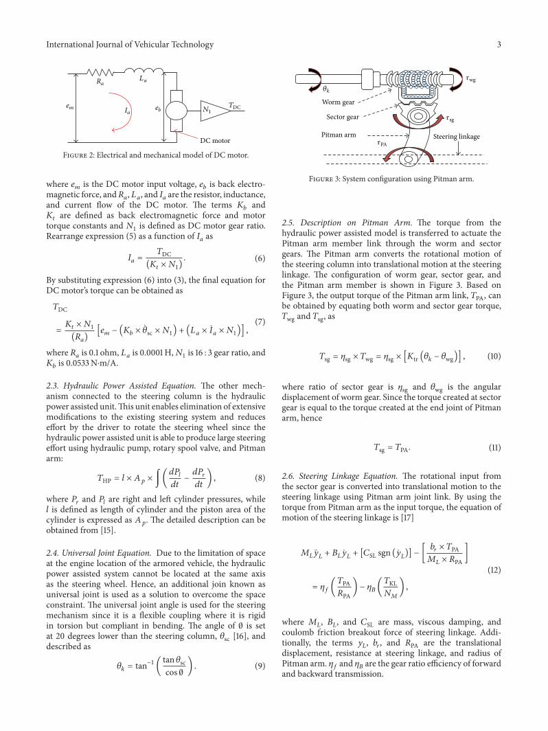
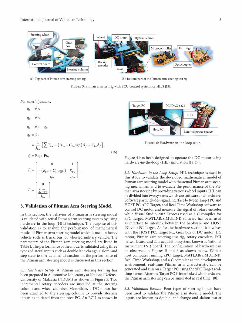
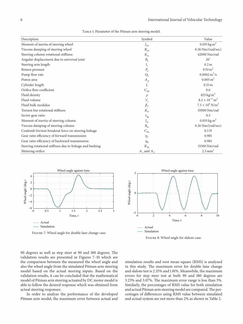
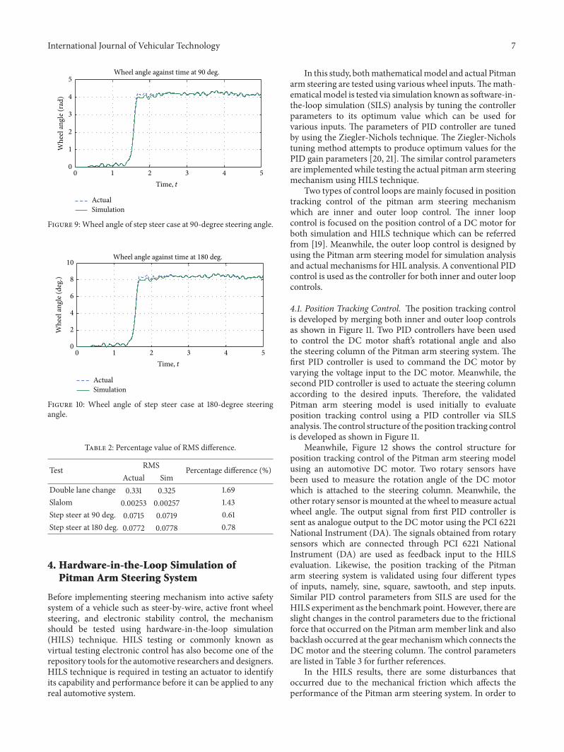
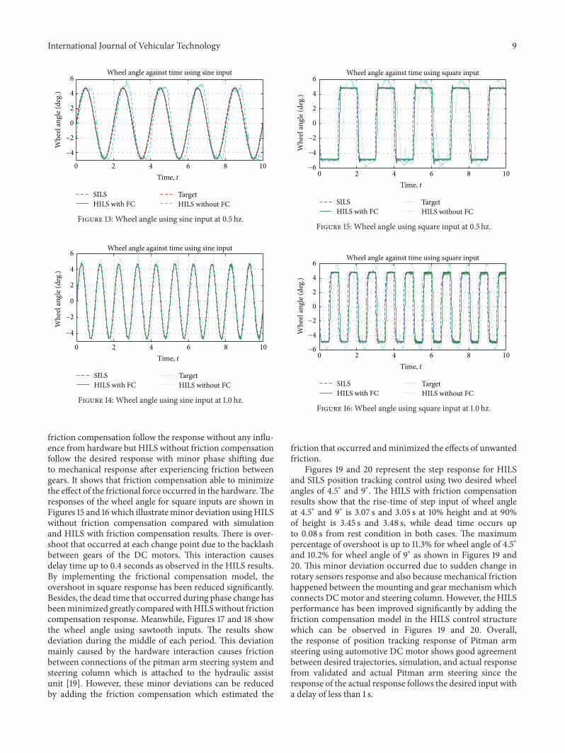
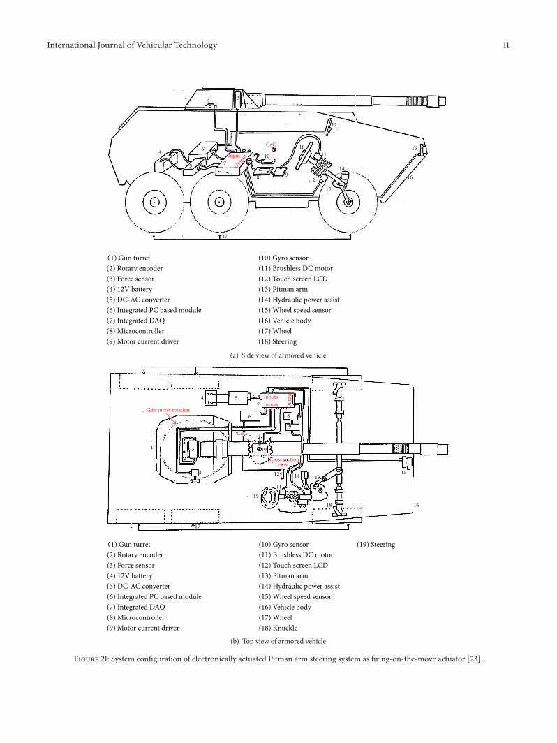

International Journal of
AerospaceEngineeringHindawi Publishing Corporationhttpwwwhindawicom Volume 2014
RoboticsJournal of
Hindawi Publishing Corporationhttpwwwhindawicom Volume 2014
Hindawi Publishing Corporationhttpwwwhindawicom Volume 2014
Active and Passive Electronic Components
Control Scienceand Engineering
Journal of
Hindawi Publishing Corporationhttpwwwhindawicom Volume 2014
International Journal of
RotatingMachinery
Hindawi Publishing Corporationhttpwwwhindawicom Volume 2014
Hindawi Publishing Corporation httpwwwhindawicom
Journal ofEngineeringVolume 2014
Submit your manuscripts athttpwwwhindawicom
VLSI Design
Hindawi Publishing Corporationhttpwwwhindawicom Volume 2014
Hindawi Publishing Corporationhttpwwwhindawicom Volume 2014
Shock and Vibration
Hindawi Publishing Corporationhttpwwwhindawicom Volume 2014
Civil EngineeringAdvances in
Acoustics and VibrationAdvances in
Hindawi Publishing Corporationhttpwwwhindawicom Volume 2014
Hindawi Publishing Corporationhttpwwwhindawicom Volume 2014
Electrical and Computer Engineering
Journal of
Advances inOptoElectronics
Hindawi Publishing Corporation httpwwwhindawicom
Volume 2014
The Scientific World JournalHindawi Publishing Corporation httpwwwhindawicom Volume 2014
SensorsJournal of
Hindawi Publishing Corporationhttpwwwhindawicom Volume 2014
Modelling amp Simulation in EngineeringHindawi Publishing Corporation httpwwwhindawicom Volume 2014
Hindawi Publishing Corporationhttpwwwhindawicom Volume 2014
Chemical EngineeringInternational Journal of Antennas and
Propagation
International Journal of
Hindawi Publishing Corporationhttpwwwhindawicom Volume 2014
Hindawi Publishing Corporationhttpwwwhindawicom Volume 2014
Navigation and Observation
International Journal of
Hindawi Publishing Corporationhttpwwwhindawicom Volume 2014
DistributedSensor Networks
International Journal of