Embed Size (px)
Citation preview
Hindawi Publishing CorporationJournal of PhotonicsVolume 2013 Article ID 528478 7 pageshttpdxdoiorg1011552013528478
Research ArticleMonitoring of Moisture in Transformer Oil Using OpticalFiber as Sensor
S Laskar and S Bordoloi
Department of EEE Don Bosco College of Engineering and Technology Assam Don Bosco University GuwahatiAssam 781017 India
Correspondence should be addressed to S Laskar shakuntalalaskarsifycom
Received 26 March 2013 Revised 21 June 2013 Accepted 1 July 2013
Academic Editor Luciano Mescia
Copyright copy 2013 S Laskar and S Bordoloi This is an open access article distributed under the Creative Commons AttributionLicense which permits unrestricted use distribution and reproduction in any medium provided the original work is properlycited
This paper describes an optical fiber sensor and temperature sensor-based instrumentation system tomeasure themoisture contentin transformer oil The sensor system consists of (i) Diode Laser Source (ii) a bare and bent multimode fiber as sensor probe (iii)an LDR as detector (iv) LM35-based temperature sensor and (v) microcontroller system having a trained ANN for processing andcalibration The bare and bent optical fiber sensor and the temperature sensor LM35 are used to provide the measures of refractiveindex (RI) and temperature of a transformer oil sample An ATmega32-microcontroller-based system with trained ANN algorithmhas been developed to determine the moisture content of the transformer oil sample by sampling the readings of the bare bentoptical fiber sensor and the temperature sensor
1 Introduction
Fiber optic sensors offer unique advantages such as immu-nity to electromagnetic interferences stability repeatabilitydurability against harsh environment and fast responseTherefore they are used for the measurement of physicalparameters such as temperature [1] pressure [2] acceleration[3] curvaturemeasurement [4] hydrocarbonmonitoring [5]and host of other applications
Power transformers are one of the most expensive invest-ments in electric power systems [6] They are fundamentalcomponents of electric power systems and their reliabilityis an important factor in the operation of the system [7]The transformer oil is a good insulating material Howeverdue to some inevitable factors some unwanted particles likewater and gas can contaminate the oil As a result insulationstrength gets reduced that may result in partial discharge oftransformer oil [8] Model-based online detection method[6] partial discharge method [7] chromatography radiofre-quency method infrared spectroscopy neural networkmethod [9] and so forth are some of the techniques devel-oped for detection of moisture content of transformer oil
The dielectric parameter (120576119903 relative permittivity) of
transformer oil indicates the quality of the oil as the insulationproperty is concerned Again square of refractive index isrepresented as relative permittivity of an optical materialTherefore themoisture content in transformer oil sample canbe related to the change in refractive index of the sampleIn fact the measure of refractive index provides informationabout the turbidity of a liquid [10] An optical fiber sensorfor measuring the refractive index of liquid based on themeasurement of the input and output power of a multimodefiber has been proposed in [11 12]
Temperature affects the dielectric property of transformeroil [13] and hence the refractive index Therefore it is neces-sary to relate the change in refractive index of transformer oilwith its temperature [14]
Microcontroller offers enormous flexibility and opportu-nity to researchers to investigate and develop sensor-basedsystem according to their requirements and applications Sev-eral microcontrollers-based instrumentation systems weredeveloped using optical fiber as a sensor [1 2] An electronicmicrocontroller-based system for high-pressure measure-ment using a fiber-optic sensor has been proposed [15] A
2 Journal of Photonics
Field distribution
Curved fiber
Power lost throughradiation
R998400
Figure 1 Schematic representation of the radiation loss of a modeat a fiber bend
digital microcontroller-based transducer has been proposedfor liquid level measurement using two optical fibers [16]
This paper describes a microcontroller-based instrumen-tation system using optical fiber and a temperature IC sensorto measure the moisture content in transformer oil A bareand bentmultimode optical fiber is used as sensor tomeasurethe RI of a transformer oil sample The optical fiber sensoris prepared by first removing a length of 5 cm of jacket andcladding of a plastic multimode fiber and then the bareportion of the fiber is made into a bend of fixed radiusof curvature The bare and bent portion of the multimodeoptical fiber is termed as ldquooptical sensor proberdquo (OSP) Alaser diode is used to launch a laser beam at one end of thefiber When the laser beam passes through the bare and bentportion of the optical fiber intensity modulation of the laserbeam takes place depending upon the RI of a transformeroil sample around it that represents the moisture content ofthe sample The laser beam at the other end (output end)of the sensor fiber is detected by an LDR-based potentialdivider circuit An ATmega32 microcontroller-based systemhas been developed to sample analog signals fromLDR-basedpotential divider circuit and from the temperature sensor ICLM35 Since the refractive index of transformer oil dependson the temperature it is imperative that both refractiveindex and temperature are to be taken into account todetermine the moisture content in a transformer oil sampleFor this purpose a trained artificial neural network is used toprocess and calibrate the input data The parameters such asweightagematrix elements and threshold of the trainedANNare stored in the microcontroller flash memory to determinemoisture content of a transformer oil sample using the inputfrom the potential divider and temperature sensor IC
2 Theory of Macrobending
When a multimode fiber is put at a sharp bend (macrobend)with a radius of curvature exceeding the critical radius ofcurvature light rays are lost in the cladding which resultsin power loss and thus attenuation Since higher modes arebound less tightly to the fiber core than the lower ordermodes the higher order modes radiate out of the fiber first[17] resulting in loss or attenuation as shown in Figure 1
For a macrobend multimode fiber the attenuation coef-ficient (without any special case of flat or graded profile) isapproximately given as [18]
120572119861=
21205742
(0)
11989911198960
exp[
[
minus
2
3
119899111989601198771015840
(
1205732
minus 1198962
01198992
2
1198992
11198962
0
minus
2119886
1198771015840)
32
]
]
(1)
where 1198771015840 represents the radius of curvature 119886 is the coreradius 119899
1and 119899
2represent the core and cladding RI of the
fiber 120573 is the propagation constant and 1198960= 120596119888
The propagation constant 120573 is expressed in normalizedform as
119887 =
(1205732
1198962
0minus 1198992
2)
1198992
1minus 1198992
2
(2)
where 0 le 119887 le 1 for a guided mode
there4 1205732
minus 1198962
01198992
2= 1198871198962
0(1198992
1minus 1198992
2) (3)
Substituting the expression for 1205732 minus 119896201198992
2in (2)
120572119861=
21198871198960(1198992
1minus 1198992
2)
1198991
times exp[
[
minus
2
3
119899111989601198771015840
(
1198871198962
0(1198992
1minus 1198992
2)
1198992
11198962
0
minus
2119886
1198771015840)
32
]
]
(4)
where 1198992is the RI of the cladding If all the parameters in (4)
aremade constant except 1198992 then the attenuationwill depend
on the cladding material or the surface which will act as acladding for the fiber
The loss of optical power (bending scattering loss radi-ation loss etc) in an optical fiber is expressed in terms ofattenuation coefficient [19] as
120572 =
10
119897
log10
119875 (119897)
119875 (0)
(5)
where 119875(119897) and 119875(0) denote the output and input power and 119897denotes the length of the fiberThe attenuation loss for a shortsection of the fiber does not scale linearly with length [14]Rearranging (5)
119875 (119897) = 119875 (0) 119890minus02304120572119897
(6)
For a multimode fiber with macrobending the attenuationcoefficient in (6) can be expressed as 120572 = 120572
119861
there4 119875 (119897) = 119875 (0) 119890minus02304120572119861119897
(7)
Now expanding the exponential term and neglecting thehigher order terms (7) becomes
119875 (119897) = 119875 (0) [1 minus 02304120572119861119897] (8)
If the cladding of the bend portion of the optical fiber isremoved and a liquid with refractive index 119899
119897is applied
Journal of Photonics 3
x1
x2
xn
sumWijxifiOj
Figure 2 An illustration of a processing neuron
around the bare and bent portion of the optical fiber (4) and(8) give us
119875 (119897) = 119875 (0)[
[
1minus
046081198871198960(1198992
1minus 1198992
119897) 119897
1198991
times exp
minus
2
3
119899111989601198771015840
(
119887 (1198992
1minus 1198992
119897)
1198992
1
minus
2119886
1198771015840)
32
]
]
(9)
Once the bare bent optical fiber sensor is prepared with fixedradius of curvature 119899
1 1198771015840 119896
0 119887 119886 and 119871 become constant
in (9) Again after fixing the LDR and Diode Laser Sourceacross the optical fiber with proper focusing 119875(0) the inputpower of the laser ray at the input end of the optical fiberalso remains constant Therefore power associated with thelaser beam at the LDR end will depend on the term (1198992
1minus 1198992
119897)
Equation (9) shows that the power associated with the laserbeam at the LDR end decreases if the RI (119899
119897) of a liquid
increases due to change in moisture content in it Thus thepower associated with the laser beam at the LDR end canbe represented as function of RI of a liquid which is appliedaround the bare bent optical fiber as follows
119875 (119897) = 119891 (1198992
1minus 1198992
119897) (10)
The electrical power loss in the LDR of the potential dividercircuit shown in Figure 6 can be expressed as
119875119871=
(119881119888119888minus 119881119909)2
119877119871
(11)
where 119877119871is the resistance of the LDR and it changes with
change in the power associated with the laser beam at theLDR end 119881
119909is the analog output signal of the potential
divider circuit which provides the measure of change in 119877119871
due to change in RI of the liquid Thus electrical power lossin the LDR of the potential divider circuit can be related asthe function of (10) as given in the following
119875 (119897) = 119891 (1198992
1minus 1198992
119897) = 119891(
(119881119888119888minus 119881119909)2
119877119871
) (12)
Since 119881119888119888
and 1198991are constant the output of the potential
divider circuit119881119909would provide themeasure of RI of a liquid
1
3
2
1
2
Input layer
OutputInput pattern
i j kWji Wkj
Hidden layer Output layer
Figure 3 Schematic illustration of multilayered feed forward(MLFF) ANN
To detector
From source
Light IN2a
Optical probe(bare and bent)
2a
Light OUT
Cladding
CladdingSensing region
n1
n1
n2
n2
nl
Figure 4 Geometry of the proposed sensor
3 Artificial Neural Networks (ANN)
The fundamental unit or building block of a neural networkis the neuron [20]The general neuron has a set of 119899 numbersof inputs 119909
119894 representing the source of input signals Each
input 119909119894is weighted before reaching the main body of the
processing element by the connection strength or the weightfactor119882
119895119894 The input signal is excitatory or inhibitory In the
former case they increase the activation of the neuron whilstin the latter they reduce it The inputs of a particular type arecombined together to give the total input to the 119895th neuronA schematic illustration of a processing node (PN) is shownin Figure 2119874119895is the output from the processing node and the node
activation is determined by an output function which isconsidered as
119891 (119909) =
1
1 + 119890minus119909 (13)
Among the various ANN architectures available in theliteratures the multilayer feed forward (MLFF) network witherror back propagation learning algorithm has been selectedfor this problem mainly because (i) it is the most simple and
4 Journal of Photonics
ADC1
ADC0
PB7
PB6
PB5
PB4
PB1
PB0
LDR
base
d po
tent
ial
divi
der c
ircui
tLM35 ATmega32
ProbeLDR
D7
D6
D5
D4
RS
E
LCD
uni
t
Laser
Vcc
Vcc = +5V
VEE RW
Figure 5 Scheme adopted for the measurement
comprehensive neural approach for model base and (ii) it hasgood generalization capability
4 Multilayer Feed Forward (MLFF) Network
In MLFF network the PNs are arranged in layers and onlyPNs in adjoint layers are connected [15] It has a minimumof three layers of PNs (i) the input layer (ii) the middle orhidden layer(s) and (iii) the output layer The informationpropagation is only in the forward direction and there areno feedback loops A MLFF network topology is shown inFigure 3
The MLFF network uses separate stages for learning andoperation The learning problem is stated as for given a setof input-output pair (cyclepattern) (119909
1 1198741) sdot sdot sdot (119909
119899 119874119899) the
connected weightage matrix element119882119895119894for each connected
ANN is determined in such a way that the network maps119909119894to 119874119894for 119894 = 1 119899 as closely as possible The error
back propagation generalized delta-rule technique is used totrain the MLFF network Back propagation technique andinterconnection weightage matrix element 119882
119895119894are adjusted
such that the error function
119864 =
119875
sum
119901minus1
119899
sum
119896minus1
(119889119875
119896minus 119874119875
119896)
2
(14)
is minimized where
119889119875
119896= desired output from 119896th node in 119875th training
pattern
119874119875
119896= actual output from 119896th node in 119875th training
pattern
119875 = the number of training pattern to input layer
119899 = number of nodes in the output layer
GND
LPFVX
IX
RL
R=45
K
Vcc = +5V
ADC0
Figure 6 The potential divider circuit
The maximization process is based on gradient descentalgorithm The interconnecting weights between 119895th layerneurons and 119894th layer neurons are modified using the follow-ing relationship
119882new119895119894= 119882
old119895119894+ 120578120575119895119874119894+ 120572 [Δ119882
old119895119894] (15)
If PN119895is an output layer PN then
120575119875
119900119896=(119889119875
119896minus119874119875
119896)
120597119891
120597119909
(16)
If PN119895is a hidden layer PN then
120575119875
ℎ119895= (sum
119896
120575119875
119900119896119882119875
119896119895)
120597119891
120597119909119894
(17)
where 119896 is overall PNs in the layer above the 119895th layerPN and 120578 and 120572 are the learning rate and momentumfactor The momentum factor and learning rate help in fasterconvergence of the algorithm Once network gets trained theresulting connection weights119882
119895119894are stored In the operation
stage the trained network is used to compute outputs from aset of inputs
5 Description of the Fiber Optic Sensor
The optical fiber sensor used for monitoring the refractiveindex of transformer oil is a plastic clad silica coremultimodefiber The fiber has a dimension of 200230 with diameter500120583m theRI of the core of the fiber (119899
1) is 148 and cladding
1198992is 146The length of the fiber is 60 cm fromwhich a length
of 5 cm has been unclad by mechanical stripping around thecentre The bare portion of the fiber is then made into abend of fixed radius of curvaturewhich constitutes the opticalsensor probe (OSP) The geometry of the fiber is shown inFigure 4
Journal of Photonics 5
Table 1 Measure of refractive index of transformer oil samples with different moisture content and temperature
Temperature Digital readings of microcontroller system with different percentage of oil-water mixtureIn ∘C Digital value 0 02 08 2 350 102 204 312 356 425 43845 092 141 283 270 368 34740 081 125 180 194 235 26135 071 82 128 137 165 18830 061 60 88 95 104 115
6 Experimental Setup for theInstrumentation System
Figure 5 shows the configuration of the experimental setupused for the measurement of moisture content of a trans-former oil sample The setup consists of an optical sensorlight source detector temperature sensor and a microcon-troller system A Diode Laser Source (Optochem Interna-tional Power 5mW) is used for launching a laser beam intothe input end of a multimode optical fiber by immersing thebare bent portion of the fiber into a transfer oil sampleWhenthe laser beam passes through the bare and bent portion ofthe optical fiber intensity modulation of the laser beam takesplace depending upon the RI of the transformer oil samplearound it that represents the moisture content of the sampleThe laser beam at the other end (output end) of the sensorfiber is detected by an LDR-based potential divider circuitThe output from the potential divider circuit via a low passfilter (LPF) is interfaced to an ATmega32 microcontrollerADC (pin number 0 ADC0 analog channel-0) A LM35temperature sensor is used to read the temperature of theoil samples at the same time The output of the LM35 sensoris fed to ADC (pin number 1 ADC1 analog channel-1) ofmicrocontroller ATmega32 The display unit of the micro-controller system consists of 16times 2 (ie two rows having 16character LCD display) LCD display unitsThe LCD has beenconfigured as a 5times 7 dot matrix 4-bit mode character displayIt is interfaced to PORT-B of microcontroller ATmega32 fordisplay control
The potential divider circuit (shown in Figure 6) consistsof an LDR in series with a fixed resistance (45 kΩ)The outputof the circuit is applied to a low pass filter circuit having acut-off frequency of 8Hz to remove the high frequency noisesassociated with the measurement circuitry
7 Experimental Procedures
The experimental procedure adopted for the generation ofdata sample to train the ANN requires the following steps
(i) The bare and bent fiber is cleaned by dipping it in100 (vv) ethanol and allows it to dry
(ii) Immersed the bare and bent portion of the opticalfiber in a transformer oil sample
(iii) The microcontroller-based system samples the valuesof 119881test liquid and the temperature
(iv) Repeat steps (i)ndash(iii) with different transformer oilsamples with differentmoisture content with differenttemperature
(v) Using these measurements an ANN is trained Soft-ware has been developed to implement the algorithmof the trained ANN in the microcontroller-basedsystem To determine the moisture content of a giventransformer oil sample the microcontroller-basedsystem samples the RI and temperature of the samplethroughADC0 andADC1 and using algorithm of thetrained ANN the moisture content of the sample isdisplayed in the LCD unit
8 Results and Discussion
To generate data cycles to train an ANN for the purpose ofcorrelating themeasure of RI and temperature of transformeroil samples to the moisture contents of the samples standardtransformer oil samples with known percentages of watercontents are preparedThese transformer oil samples are thensubjected to temperature variation from 30∘ to 50∘C and themicrocontroller-based system is used to samples the measureof temperature and RI of the transformer oil samplers Theexperimental results with different percentages of moisturecontent and temperatures for different transformer oil sam-ples are presented in Table 1
The plot for concentration of different transformer oilsamples versus the measure of RI of the transformer oilsamples with variation of temperature is shown in Figure 7
TheANNused for the purpose of correlating themeasureof RI and temperature of transformer oil samples to theirmoisture contents contains two neurons at the input layerfour neurons at the hidden layer and one neuron at the outputlayer as shown in Figure 8 The measure of temperature andrefractive index represented in Table 1 are taken as the inputto the ANN input layerThe output layer of the ANNwith oneneuron provides the moisture content of the transformer oilsample
The experimental results presented in the Table 1 pro-vided 25 training cycles for temperature range 30∘ndash50∘C andmoisture content range from 00 to 30 Back propagationtechnique is used to train the ANN using these 25 data cyclesThe training of the ANN is terminated when differencebetween calculated output from the ANN and desired outputbecomes less than 00001 The variation of error at the
6 Journal of Photonics
0
100
200
300
400
0 1 2 3 4
Dig
ital v
olta
ge (V
)
Concentration (vv )
50 ∘C30 ∘C35 ∘C
45 ∘C40 ∘C
Figure 7 Concentration versus output voltages
Moisture contentof transformer oilTemperature
RIInput layer
Hidden layer
OutputLayer
OutputInput pattern
1
2
3
1
2
1
4
i j k
Wji Wkj
Figure 8 Configuration of MLFF ANN used to correlate themeasure of RI and temperature of a transformer oil sample to itsmoisture content
output neuron with respect to the iteration count is shownin Figure 9
The weightage matrix elements for the trained ANN areprovided in the appendix The ANN algorithm with thesetrained weightage matrix elements is implemented in themicrocontroller-based system to determine the percentagemoisture content of transformer oil by measuring its refrac-tive index and temperature
It has been observed that without the LPF the reading ofthe LDR-based potential divider circuit keeps fluctuating byminus25 to +25 decimal values around the base value This is dueto the noise of the electronic devices and the high frequencynoise of the power supply The use of a passive LPF circuit(R-C circuit) with cut-off frequency of 8Hz brings down thisfluctuation by minus2 to +2 only
0
005
01
015
0 20 40 60
Max
imum
erro
r
Number of iterations
Figure 9 Error curve for the MLFF network
9 Conclusions
This paper describes an instrumentation system to measuremoisture content in a transformer oil sample using themeasure of RI and temperature of the sample A bare and bentmultimode optical sensor is used to measure the RI of thesample and LM35 is used as temperature sensor The noiseis associated with the measurement (measurement of RI)To generate data cycles to train an ANN for the purpose ofcorrelating themeasure of RI and temperature of transformeroil samples to the moisture contents of the samples standardtransformer oil samples with known percentages of watercontents are prepared These transformer oil samples arethen subjected to temperature variation from 30∘ to 50∘Cand the microcontroller-based system is used to samplesthe measure of temperature and RI of the transformer oilsamples Software has been developed to implement thealgorithm of the trained ANN in the microcontroller-basedsystem Therefore the microcontroller-based system candetermine the moisture content of a transformer oil sampleat any temperature between temperature range 30∘ndash50∘C bysampling the RI and temperature of the sample throughADC0 and ADC1
Appendix
Weightage matrix elements between input and hidden layersand hidden layer and output layer for the trained ANN are asfollows
(1) between first neuron and the neuron of hidden layer
11988211= minus51237881
11988212= 63035744
11988213= 02
11988214= 02
(2) between second neuron and the neuron of hiddenlayer
11988221= minus51237881
11988222= 63035744
11988223= 02
11988224= 02
Journal of Photonics 7
(3) between hidden layer neurons and output layer neu-rons
11988211= 26923553
11988221= 26923553
11988231= minus27902664
11988241= minus27902664
References
[1] D Hazarika K C Sarma and P K Sarmah ldquoMicroprocessor-based temperature monitoring system using optical fibersrdquoIEEE Sensors Journal vol 9 no 9 pp 1025ndash1028 2009
[2] D Hazarika and D S Pegu ldquoMicrocontroller based air pressuremonitoring instrumentation system using optical fibers assensorrdquo Optical Fiber Technology vol 19 pp 83ndash87 2013
[3] D R Miers D Raj and J W Brthold ldquoDesigned and charac-terization of optical fiber acceleratometersrdquo in Fiber Optic andLaser Sensors V vol 838 of Proceedings of SPIE pp 314ndash317 SanDiego Calif USA 1987
[4] R Liu Z Fu Y ZhaoQCao and SWang ldquoOperation principleof a bend enhanced curvature optical fiber sensorrdquo in Pro-ceedings of the IEEERSJ International Conference on IntelligentRobots and Systems (IROS rsquo06) pp 1966ndash1971 October 2006
[5] F Prudenzano L Mescia L A Allegretti et al ldquoDesign of anoptical sensor array for hydrocarbon monitoringrdquo Optical andQuantum Electronics vol 41 no 1 pp 55ndash68 2009
[6] WHribernik G Pascoli andK Frohlich ldquoAn advancedmodel-based diagnosis system for online detection of the moisturecontent of power transformer insulationsrdquo in Proceedings ofthe IEEE International Symposium on Electrical Insulation(ISEI rsquo08) pp 187ndash191 June 2008
[7] G F C Veloso L E B Silva I Noronha and G LambertTorres ldquoUsing partial discharge as sample signal source toidentify contamination moisture pattern in power transformerinsulating oilrdquo in Proceedings of the 36th Annual Conference ofthe IEEE Industrial Electronics Society (IECON rsquo10) pp 1041ndash1044 November 2010
[8] C-P Zhu Y-L HuangM-L Shan and L-H Lu ldquoThe researchof moisture detection in transformer oil based on ultrasonicmethodrdquo in Proceedings of the 2nd International Conference onInformation Science and Engineering (ICISE rsquo10) pp 1621ndash1624December 2010
[9] W-G Chen D-G Gan andQ Liu ldquoOn-linemonitoringmodelbased on neural network for moisture content in transformeroilrdquo High Voltage Engineering vol 33 no 5 pp 73ndash78 2007
[10] A Banerjee S Mukherjee R K Verma et al ldquoFiber opticsensing of liquid refractive indexrdquo Sensors and Actuators B vol123 no 1 pp 594ndash605 2007
[11] T Takeo and H Hattori ldquoOptical fiber sensor for measuringrefractive indexrdquo Japanese Journal of Applied Physics vol 21 no10 pp 1509ndash1512 1982
[12] A L Chaudhari andAD Shaligram ldquoMulti-wavelength opticalfiber liquid refractometry based on intensity modulationrdquoSensors and Actuators A vol 100 no 2-3 pp 160ndash164 2002
[13] R Shoureshi V Permana R Wood R Swartzendruber andM Simoes ldquoOptical sensor for transformer monitoringrdquo Intel-ligent Transformer Monitoring System Utilizing Neuro-FuzzyTechnique Approach PSERC 04-27 2004
[14] M Koch S Tenbohlen and T Stirl ldquoAdvanced online moisturemeasurement in power transformerrdquo in Proceedings of the Inter-national Conference on Condition Monitoring and Diagnosis(CMD rsquo06) April 2006
[15] A Barwicz andW J Bock ldquoAn electric high-pressuremeasuringsystem using a polarimetric fiber-optic sensorrdquo IEEE Transac-tions on Instrumentation and Measurement vol 39 no 6 pp976ndash981 1990
[16] G Betta A Pietrosanto and A Scaglione ldquoMicrocontroller-based performance enhancement of an optical fiber leveltransducerrdquo IEEE Transactions on Instrumentation and Mea-surement vol 47 no 2 pp 489ndash493 1998
[17] G Keiser Attenuation Optical Fiber Communication McgrawHill 2nd edition 1991
[18] D Gloge ldquoBending loss in multimode fibers with graded andungraded core fibersrdquo Applied Optics vol 11 no 11 pp 2506ndash2513 1972
[19] B P Pal ldquoCharacterization of optical fibers for telecommu-nication and sensors-Multimode fibers fundamentals of fibreopticsrdquo in Telecommunication and Sensor Systems pp 264ndash267New Age International 1st edition 2009
[20] DHazarika K C Sarma andN Baruah ldquostatic voltage stabilityindication in a power system using ANNrdquo IJMAN vol 2 no 1pp 44ndash49 2012
Submit your manuscripts athttpwwwhindawicom
Hindawi Publishing Corporationhttpwwwhindawicom Volume 2014
High Energy PhysicsAdvances in
The Scientific World JournalHindawi Publishing Corporation httpwwwhindawicom Volume 2014
Hindawi Publishing Corporationhttpwwwhindawicom Volume 2014
FluidsJournal of
Atomic and Molecular Physics
Journal of
Hindawi Publishing Corporationhttpwwwhindawicom Volume 2014
Hindawi Publishing Corporationhttpwwwhindawicom Volume 2014
Advances in Condensed Matter Physics
OpticsInternational Journal of
Hindawi Publishing Corporationhttpwwwhindawicom Volume 2014
Hindawi Publishing Corporationhttpwwwhindawicom Volume 2014
AstronomyAdvances in
International Journal of
Hindawi Publishing Corporationhttpwwwhindawicom Volume 2014
Superconductivity
Hindawi Publishing Corporationhttpwwwhindawicom Volume 2014
Statistical MechanicsInternational Journal of
Hindawi Publishing Corporationhttpwwwhindawicom Volume 2014
GravityJournal of
Hindawi Publishing Corporationhttpwwwhindawicom Volume 2014
AstrophysicsJournal of
Hindawi Publishing Corporationhttpwwwhindawicom Volume 2014
Physics Research International
Hindawi Publishing Corporationhttpwwwhindawicom Volume 2014
Solid State PhysicsJournal of
Computational Methods in Physics
Journal of
Hindawi Publishing Corporationhttpwwwhindawicom Volume 2014
Hindawi Publishing Corporationhttpwwwhindawicom Volume 2014
Soft MatterJournal of
Hindawi Publishing Corporationhttpwwwhindawicom
AerodynamicsJournal of
Volume 2014
Hindawi Publishing Corporationhttpwwwhindawicom Volume 2014
PhotonicsJournal of
Hindawi Publishing Corporationhttpwwwhindawicom Volume 2014
Journal of
Biophysics
Hindawi Publishing Corporationhttpwwwhindawicom Volume 2014
ThermodynamicsJournal of
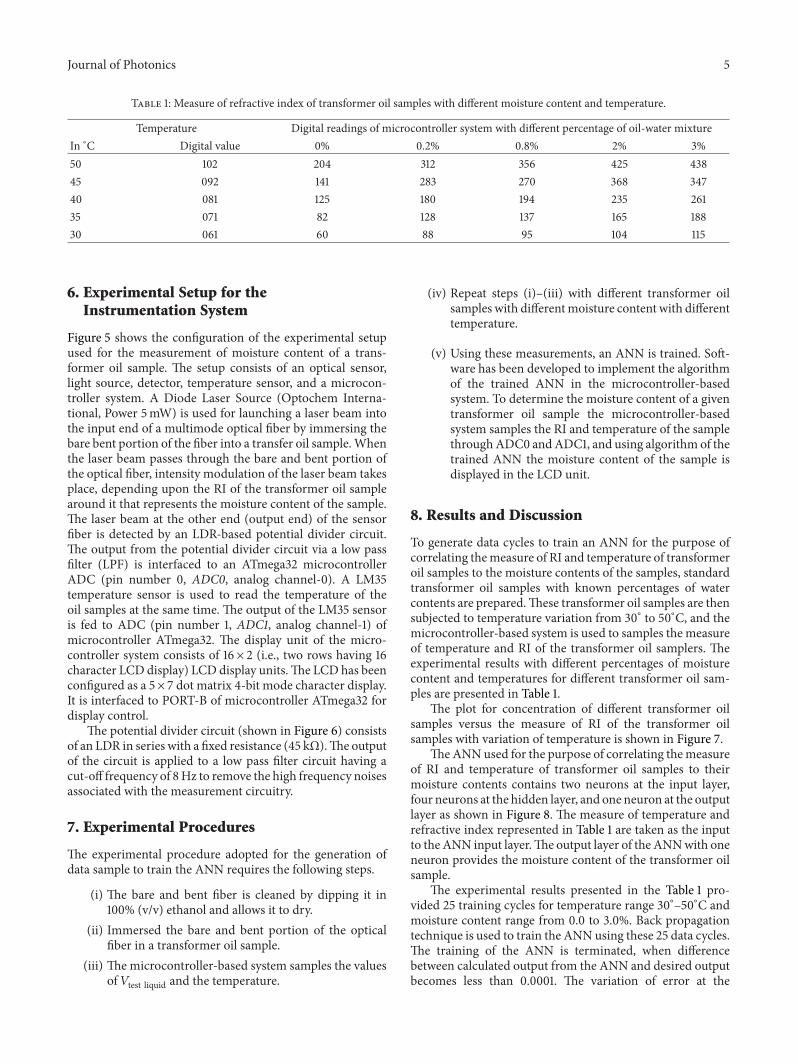