Embed Size (px)
Citation preview
Research ArticleNew Joining Technology for OptimizedMetalComposite Assemblies
Holger Seidlitz Lars Ulke-Winter and Lothar Kroll
Institute of Lightweight Structures Chemnitz University of Technology 09107 Chemnitz Germany
Correspondence should be addressed to Holger Seidlitz holgerseidlitzmbtu-chemnitzde
Received 20 February 2014 Accepted 23 May 2014 Published 3 September 2014
Academic Editor Jie Han
Copyright copy 2014 Holger Seidlitz et alThis is an open access article distributed under the Creative Commons Attribution Licensewhich permits unrestricted use distribution and reproduction in any medium provided the original work is properly cited
The development of a new joining technology which is used tomanufacture high strength hybrid constructions with thermoplasticcomposites (FRP) andmetals is introduced Similar to natural regulation effects at trees fibers around the FRP joint become alignedalong the lines of force and will not be destroyed by the joining processThis is achieved by the local utilization of the specific plasticflow properties of the FRT andmetal component Compared with usual joining methodsmdashsuch as flow drill screws blind and self-piercing rivetsmdashnoticeably higher tensile properties can be realized through the novel process management The load-bearingcapability increasing effect could be proved on hybrid joints with hot-dip galvanized steel HX420LAD and orthotropic glassmdashaswell as carbonmdashfiber reinforced plastics The results which were determined in tensile-shear and cross-shear tests according toDIN EN ISO 14273 and DIN EN ISO 14272 are compared with holding loads of established joining techniques with similar joiningpoint diameter and material combinations
1 Introduction
In the automotive industry the trend towards the useof lightweight materials is particularly strong it is beingassumed that the proportion of fiber-reinforced thermoplas-tics (FRP)will continue to rise in themedium termTheback-grounds to this are not the least requirements for reductionin CO
2emissions for fleet consumption For this FRP offermdash
due to the high specific properties and good recyclabilitymdashspecial advantages [1ndash3] Similar to construction principlesin nature the fiber architecture of the textile can be optimallyadapted to the complex and often superimposed loads Dueto the low synthesis temperature several functional elementsare also integrable in FRP structures
For new vehicle concepts in multimaterial design(MMD) textile reinforced thermoplastics like thermoform-able organic sheets can make a significant contribution toenhance the lightweight-properties and accordingly alsoto resource conservation Organic sheets have a higherspecific energy absorption capacity than comparable sheetmetal-based constructions and are thus predestined forcrash-absorbing applications in car bodies [4ndash6]
Manufacturing FRPmetal-hybrids can be realized bynonpositive (friction-based) as well as positive or firmlybonded joining approaches They generally require severalextra joining elements which increase the weight of theassembly In addition the components to be joined mustundergo extensive preliminary operations This may includedrilling of holes for bolted or riveted joints or activationof the joining surface by etching grinding and degreasingfor adhesive bonding [7 8] Drilling in particular as well aspunching holes in connecting elements by means of a sharptool results in undesirable fiber breakage in the compositeat the joining point of the FRP This interrupts the flow offorce (force flux) in the reinforcing fibers which means thatthe great potential of the fiber-reinforced composite can beexploited only to a limited extent [9 10]
Therefore the structural multimaterial design (MMD)with fiber-reinforced thermoplastics consequently requiresload-capable joining systems that do not interrupt the flux offorces in load bearing fibers around the joining point
New technology concepts derived from thermoformingprocesses like flow drilling at metal sheets and thermo-forming of load adjusted holes at thermoplastic composites
Hindawi Publishing CorporationJournal of EngineeringVolume 2014 Article ID 958501 11 pageshttpdxdoiorg1011552014958501
2 Journal of Engineering
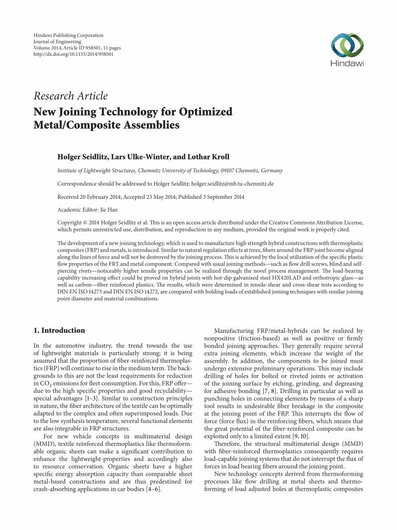
Figure 1 Reducing the stress concentration on knotholes of trees byload adjusted fiber orientation at the defect zone
can be used as a solution approach For the first time thefusion and adaptation of both technologies allow tolerant andreproducible joining of both material systems within a shortprocess time according to design principles in nature
2 Optimization of FRP-Joints followingExamples in Nature
Analyzing the structural regulation principles in nature andadapting to defect zones provides a blueprint for the shapeoptimization of a joining point For instance maintenanceof a uniform stress distribution in the disturbed zone isobserved in trees [11 12] If a tree sustains damage by cracksrottenness or broken branches a local structural weaknessoccurs The resultant increased stress can be diminished bybuilding up material in the vicinity of the defect [13 14]Figure 1 shows how wood fibers are redirected radial atdefects (eg caused by knotholes) as a way to counteract theldquodangerousrdquo notch effects
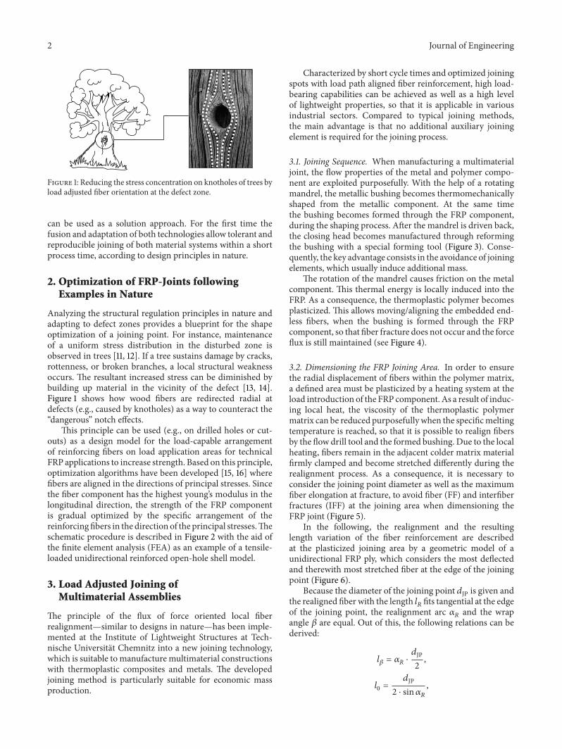
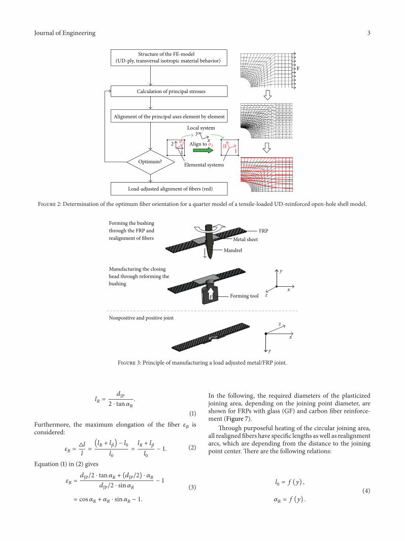
This principle can be used (eg on drilled holes or cut-outs) as a design model for the load-capable arrangementof reinforcing fibers on load application areas for technicalFRP applications to increase strength Based on this principleoptimization algorithms have been developed [15 16] wherefibers are aligned in the directions of principal stresses Sincethe fiber component has the highest youngrsquos modulus in thelongitudinal direction the strength of the FRP componentis gradual optimized by the specific arrangement of thereinforcing fibers in the direction of the principal stressesTheschematic procedure is described in Figure 2 with the aid ofthe finite element analysis (FEA) as an example of a tensile-loaded unidirectional reinforced open-hole shell model
3 Load Adjusted Joining ofMultimaterial Assemblies
The principle of the flux of force oriented local fiberrealignmentmdashsimilar to designs in naturemdashhas been imple-mented at the Institute of Lightweight Structures at Tech-nische Universitat Chemnitz into a new joining technologywhich is suitable to manufacture multimaterial constructionswith thermoplastic composites and metals The developedjoining method is particularly suitable for economic massproduction
Characterized by short cycle times and optimized joiningspots with load path aligned fiber reinforcement high load-bearing capabilities can be achieved as well as a high levelof lightweight properties so that it is applicable in variousindustrial sectors Compared to typical joining methodsthe main advantage is that no additional auxiliary joiningelement is required for the joining process
31 Joining Sequence When manufacturing a multimaterialjoint the flow properties of the metal and polymer compo-nent are exploited purposefully With the help of a rotatingmandrel the metallic bushing becomes thermomechanicallyshaped from the metallic component At the same timethe bushing becomes formed through the FRP componentduring the shaping process After the mandrel is driven backthe closing head becomes manufactured through reformingthe bushing with a special forming tool (Figure 3) Conse-quently the key advantage consists in the avoidance of joiningelements which usually induce additional mass
The rotation of the mandrel causes friction on the metalcomponent This thermal energy is locally induced into theFRP As a consequence the thermoplastic polymer becomesplasticized This allows movingaligning the embedded end-less fibers when the bushing is formed through the FRPcomponent so that fiber fracture does not occur and the forceflux is still maintained (see Figure 4)
32 Dimensioning the FRP Joining Area In order to ensurethe radial displacement of fibers within the polymer matrixa defined area must be plasticized by a heating system at theload introduction of the FRP component As a result of induc-ing local heat the viscosity of the thermoplastic polymermatrix can be reduced purposefully when the specificmeltingtemperature is reached so that it is possible to realign fibersby the flow drill tool and the formed bushing Due to the localheating fibers remain in the adjacent colder matrix materialfirmly clamped and become stretched differently during therealignment process As a consequence it is necessary toconsider the joining point diameter as well as the maximumfiber elongation at fracture to avoid fiber (FF) and interfiberfractures (IFF) at the joining area when dimensioning theFRP joint (Figure 5)
In the following the realignment and the resultinglength variation of the fiber reinforcement are describedat the plasticized joining area by a geometric model of aunidirectional FRP ply which considers the most deflectedand therewith most stretched fiber at the edge of the joiningpoint (Figure 6)
Because the diameter of the joining point 119889JP is given andthe realigned fiber with the length 119897
119877fits tangential at the edge
of the joining point the realignment arc 120572119877and the wrap
angle 120573 are equal Out of this the following relations can bederived
119897120573= 120572119877sdot119889JP
2
1198970=119889JP
2 sdot sin120572119877
Journal of Engineering 3
Structure of the FE-model(UD-ply transversal isotropic material behavior)
Calculation of principal stresses
Alignment of the principal axes element by element
Optimum
Load-adjusted alignment of fibers (red)
Elemental systems
Local systemy
x
III2
1
Align to 120590I
F
120590I
Figure 2 Determination of the optimum fiber orientation for a quarter model of a tensile-loaded UD-reinforced open-hole shell model
FRPMetal sheet
Mandrel
y
zx
Forming toolF
z
x
y
Forming the bushingthrough the FRP andrealignment of fibers
Manufacturing the closinghead through reforming thebushing
Nonpositive and positive joint
F
Figure 3 Principle of manufacturing a load adjusted metalFRP joint
119897119877=119889JP
2 sdot tan120572119877
(1)Furthermore the maximum elongation of the fiber 120576
119861is
considered
120576119861=998779119897
119897=(119897119877+ 119897120573) minus 1198970
1198970
=119897119877+ 119897120573
1198970
minus 1 (2)
Equation (1) in (2) gives
120576119861=119889JP2 sdot tan120572119877 + (119889JP2) sdot 120572119877119889JP2 sdot sin120572119877
minus 1
= cos120572119877+ 120572119877sdot sin120572
119877minus 1
(3)
In the following the required diameters of the plasticizedjoining area depending on the joining point diameter areshown for FRPs with glass (GF) and carbon fiber reinforce-ment (Figure 7)
Through purposeful heating of the circular joining areaall realigned fibers have specific lengths aswell as realignmentarcs which are depending from the distance to the joiningpoint center There are the following relations
1198970= 119891 (119910)
120572119877= 119891 (119910)
(4)
4 Journal of Engineering
2
1
3
4
z
x
(1)(2)(3)(4)
Metal sheetClosing headFibers of the FRPArea of fiber realignment
Figure 4 Schematic view of realigned fibers at the joint of anorthotropic FRP
The boundaries of the plasticized joining area can bedescribed by the circle equation
1199092+ 1199102= (119889PA2)
2
(5)
so that every length 1198970of an unloaded fiber in the plasticized
joining area can be determined Therewith it follows for 119909 =1198970(119910)
1198970(119910) = radic
1
4sdot 119889PA2minus 1199102 (6)
The realignment of fibers occurs at the joint in the intervalbetween 0 le 119910 le 119889JP2 At the same time the fibers whichlie flat at edge of the joining point at 119910 = 0 are highlystressed From 119910 = 119889JP2 which corresponds to the radiusof the joining point (Figure 6) fibers are not stretched Forthe realignment arc 120572
119877follows therewith
tan120572119877=119889JP2 minus 119910
1198970(119910) (7)
Insert (6) in (7) gives the realignment arc 120572119877as a function of
the 119910-coordinate for every realigned fiber of the plasticizedjoining area
120572119877(119910) = arctan(
119889PA minus 119910
radic(14) sdot 119889PA2minus 1199102) (8)
With (8) considering (3) the strain of every fiber can bedetermined in the plasticized joining area as long as 120572
119877is
small
120576119861(119910) = cos(arctan(
119889PA minus 119910
radic(14) sdot 119889PA2minus 1199102))
+ arctan(119889PA minus 119910
radic(14) sdot 119889PA2minus 1199102)
sdot sin(arctan(119889PA minus 119910
radic(14) sdot 119889PA2minus 1199102))minus 1
(9)
Figure 8 shows the resulting strain course from (9) at CFRPandGFRP joint with a joining point diameter of119889Jp = 53mm
This shows that the located filaments at the joining pointare prestressed in the region of the maximum fiber strainFurther tensile stresswould cause fiber fracture and therewithpremature component failure To exploit the high potentialof FRP component optimally it is necessary to choosea larger diameter of the plasticized joining area Internalmaterial friction which is caused during the realignment bysuperimposed drifting fibers in the plasticized matrix wasnot considered in the model
The arrangement of filaments in thickness direction alsorequires an increased plasticized joining area at the FRP jointIn the following this parameter was chosen for GFRPmetaljoints with 200mm and CFRPmetal joints with 300mm fora joining point diameter of 53mm (Figure 7)
33 Development and Implementation of a Joining Device Toimplement the described joining sequence technologicallyan automated joining device was designed andmanufactured(Figure 9)
Before joining the metal and the FRP component arefixed in the cavity (11) by the fixing unit (Figure 9(d)) Afterclosing the cavity the rotating flow drill tool (6) will beinserted by the electromechanical drilling unit (5) throughthe borehole of the fixing plate (9) (Figure 9(b))Theplasticiz-ing process can be supported at higher wall thicknesses witha special hot air heating system (1)The specific plasticizationdiameter of the joining area can be set through the diameterof the nozzle output at the cavity So there is one cavity platefor joining GFRP with 200mm and another one for CFRPwith a diameter of 300mm
After the bushing is formed through the FRP componentthe fixing plate is reset by the pneumatic cylinders (7 and10) and the abutment plate (8) moved forward so that thecavity is closed and the forming process can be started bythe forming unit (Figure 9(c)) For that the forming tool (2)will be pressed by the pneumatic cylinder (4) in the bushingso that it is everted With the help of force transducerwhich is arranged between the pneumatic cylinder and theforming tool the forming force can be set Through the useof a Programmable Logic Controller (PLC) the repeatable
Journal of Engineering 5
GFRP
IFFFF
IFF IFFFF
IFF
CFRPFF
IFF IFFFF
IFF IFF
Closing head
Realigned fibers(a) (b)
Realigned fibers
Figure 5 FF and IFF caused by too small plasticization area (a) at hybrid joints with glass (GFRP) and (b) carbon fiber reinforced plastics(CFRP)
lR
l120573
120572R120573
P
y
l0
x
dPA
dJP
l0
P
lR
l120573
120572R
120573
Diameter of the plasticized joining areaDiameter of the joining pointLength of the unloaded fiberIntersection of the tangentLength of the realigned fiber until P
Arc lengthRealignment arcWrap angle at the edge of the joining point
dPA
dJP
Figure 6 Geometric model description of an unidirectional plywith themost deflected fiber and required diameter of the plasticizedjoining area
control of the pneumatic drives and the hot air heating systemas well as the drilling unit and the spindle are guaranteedThePLC and other special assemblies such as the frequency andthe safety devices are arranged in a cabinet below themachinetable (12) On a control panel it is possible to enter material-specific joining parameters like spindle speed the positions ofthe switching points the required feed rates and the heatingtime (Figure 10)
0
10
20
30
40
50
60
0 1 2 3 4 5 6 7 8 9 10dJP (mm)
dPA
(mm
)
120576CF = 18120576GF = 45
Figure 7 Required diameter of the plasticizing area at the FRP jointdepending on the joining point diameter
005
115
225
335
445
0 05 1 15 2 25 3
120576 B(y)
()
y (mm)dJP = 53mm
Glass fiberCarbon fiber
dJP
2
Figure 8 Strain of reinforcement fibers at the edge of the joiningpoint in the plasticized joining area
4 Strength Behavior of High StrengthFRPMetal Joints
41 Materials and Tests To characterize the strength behav-ior of the multimaterial joining system lap-shear and
6 Journal of Engineering
Table 1 Specification of tests and materials
Cross-tension test (DIN EN ISO 14273) Lap-shear test (DIN EN ISO 14272)
50mm
150
mm
35
mm
175
mm
GFRP CFRP MetalFiber E-Glas Carbon Deep drawing steel DC04Matrix PP PA 6Lay up [090]
119904[090090]
119904mdash
Thickness 119905 10mm 15mm 15mmFiber volume 120593 035 055 mdash
Manufacturing parametersJoining point diameter 53mm
Flow drill speed 3000minJoining force 20 kN
Plasticization diameter GFRP 200mm CFRP 300mm
cross-tension tests according to DIN EN ISO 14273 andDIN EN ISO 14272 were realized For that hybrid jointswith deep-drawing steel DC04 and orthotropic reinforcedpolypropylene (PP) as well as polyamide 6 (PA6) weremanufactured Table 1 summarizes the investigated joiningmaterial and production parameters
42 Strength Influence of Realigned Fibers at GFRP andCFRP Joints The load adjusted design of the load intro-duction at GFRP and CFRP components increases the lap-shear strengths significantly Compared with conventionalpredrilled FRP the amount of load bearing fibers will not bereduced by the new joining process Thereby it is possible toreduce dangerous notch and bearing stress effects at the edgeof FRP joints so that considerably higher lap-shear strengthcan be transferred (Figure 11)
43 Influence of the FRP Wall Thickness The innovativejoining process in addition to the previously illustratedjoining studies with thin FRPs is suitable for joints withrelatively thick-walled composite structures Referred to thewall thickness of the FRP component the load-bearingcapacity of the hybrid joining system increases until 14-foldof the metal thickness (15mm) which is equal to a FRP wallthickness of 20mm (Figure 12)
Furthermore a gradual abatement of the strength behav-ior is observed at tensile-shear loaded joints In contrast thedetermined cross-tension holding forces decrease strongly ata FRP wall thickness of 20mm which is primarily causedby the reduced overlap length of the closing head flanksAs a result the influence of the nonpositive character isnotably declined so that the joining strength decreases withintensifying FRP wall thickness and is mostly determined bythe form lock of the joining point
44 Comparisonwith Established JoiningMethods To rate thestrength behavior of the new developed joining technologylap-shear and cross-tension tests were carried out on estab-lished punctiform joints with equal material combinationsas well as similar joining point diameters In contrast tohybrid joints with FDS screws blind and semihollow rivetsnoticeable higher failure loads are achieved in lap-shear testswhich can be explained by the integrative joining sequenceand the load adjusted design of the FRP joint Althoughthe supporting surface of the closing head is less similarholding forces as FDS joints can be obtained in cross-tensiontests However the results of the strength tests confirmthat for both types of loads noticeable increased load-bearing capacities can be realized as well as a reduced weight(Figure 13)
Journal of Engineering 7
121
(a)
5
6
(b)
2
3
4
(c)
10
87
911
(d)
Figure 9 Joining device for themanufacturing of heavy duty hybridjoints (a) basic components (b) flow drill unit (c) forming unitand (d) fixing unit (1) Hot air heating system with ring nozzle(2) forming tool (3) force transducer (4) pneumatic cylinder forforming closing head (5) drilling unit (6) flow drill tool (7)pneumatic cylinderabutment (8) abutment plate (9) fixing plate(10) pneumatic cylinderfixing plate (11) cavity with nozzle outputand (12) machine table
5 Discussion
Towards conventional techniques the new load adjustedjoining process occurs from the metal side and is supportedby heat This joining sequence in particular serves the FRPcomponent because fiber and interfiber fracture can beavoided at the joint However it can be seen that the realignedfibers are not only oriented in the direction of force-flux butare also more concentrated in the joining spot than those inthe rest of the material sections (Figure 14)
Caused by the radial displacement of fibers at the formingprocess of the bushing and through the formation of theclosing head by the forming tool noticeable higher fiber
Workspace
Control panel
CabinetPneumatic cylinderforming unit
Figure 10 Joining device for manufacturing heavy duty hybridjoints
2250
1348
1670
Load adjusted joining
615
Predrilled boreholes
DC04GFRP DC04CFRP
2400
1200
1600
2000
400
800
0
Fm
ax(N
)
Figure 11 Lap-shear strengths of DC04GFRP and DC04CFRPjoints with load adjusted formed and predrilled FRP bore holes
concentration is achieved which decreases at a distance of119886 = 25mm to the normal level (120593 = 035) of GFRP com-ponent (Figure 15)
The area of the fiber realignment is marked by the typicalspandrel The check measurement at the top plies of the FRPcomponents confirms that the size of the plasticizing areafor joining pointsmdashwith a diameter of 53mmmdashwas chosencorrectly to guarantee the flexibility of the fibers (cf Figures7 and 16)
In particular orientations of glass fibers in every single plycould be determined at the joint by incinerating the polymermatrix system (Figure 17) A nondestructive realignment ofthe reinforcing fibers is observed mainly at the closing headside unidirectional ply (Figure 17(a)) In spite of that a littleamount of fiber fracture is observed at inner plies (Figures17(b) and 17(c)) The intensity of FF increases up to the metalsheet (Figure 17(d))
Furthermore the orientations of the load path redirectedfibers at the connection point can be proved by the useof computer tomography (CT) analyzing technology Apart
8 Journal of Engineering
Lap-shear test
Cross-tension test
GFRPGFRPGFRP GFRPGFRP GFRP400
800
1200
1600
2000
Fm
ax(N
)
[090]s [0900]s [(090)2]s [(090)20]s [(090090)2]s [(090)4]st = 10mm t = 15mm t = 20mm t = 27mm t = 32mm t = 37mm
Figure 12 Failure loads of load adjusted hybrid joints in dependence of the FRP thickness exemplarily illustrated by DC04GFRP joints
0
400
800
1200
16000g
55 g
27 g
13 g
Reference(load adjusted)
EJOT FDSM5 times 20
Blind rivet5 times 8 AlSt
SemihollowRivet 53 times 5
Lap-shear testCross-tension test
Fm
ax(N
)
Figure 13 Failure loads of typical joining techniques compared with load adjusted hybrid DC04GFRP joints
aGFRP
DC04
a = 04mm a = 16mm a = 36mm120593 = 078 120593 = 058 120593 = 035
10mm
Figure 14 Micro section of a DC04GFRP joint and analysis of the fiber volume
30405060708090
100
120593(
)
0 02 04 06 08 1 12 14 16 18 2 22 24a (mm)
Figure 15 Fiber content in dependence of the distance to the edge of the joining point
Journal of Engineering 9
dPA = 20mm
(a)
dPA = 30mm
y
x
(b)
Figure 16 Realigned fibers at the top plies of (a) DC04GFRP and (b) DC04CFRP joints (right)
(a) 0∘-ply (b) 90∘-ply
(c) 90∘-ply
FF
x
y
(d) 0∘-ply
Figure 17 Analyzing the fiber orientation of DC04GFRP joints by incineration
from the tangential realigned course of the reinforcing fibersit is visible that fiber fracture occurs at the joining point edgesof the FRP component (Figure 18)
Fiber fractures (FF) are usually caused by the new joiningprocess during formation of the bushing Unlike the closinghead-sided UD layers which will be first pierced in the latercourse of the process by the rotating mandrel and thus willbe expanded continuously the UD layers at the metal sheetget in contact for the first time primarily with the formedbushing
Once the mandrel pierces the metal sheet a sharp-edgedsleeve is formedHowever at this time themandrel is situated
within the sleeve and therefore does not contribute to asteady realignment of all fibers in the load introduction areaWith that fibers are partially cut by the sharp edges ofthe formed bushing until the mandrelmdashwith increasing loadadjusted realignment fibersmdashcompletely penetrates the FRPcomponent
6 Summary
Typical mechanical joining techniques such as screwingbolting and riveting are causing fiber fractures at the FRPjoint when manufacturing a FRPmetal hybrid As a result of
10 Journal of Engineering
FF
xy
z
FF
FF
(a)
15mm
015mm
x
y
(b)
Figure 18 CT scan (voxel-resolution 48 120583m) of hybrid joints (a) three-dimensional view of GFRP with marked fiber orientations and (b)top view and detail view of CFRP edge with labeled fiber orientation
the interrupted force flux critical failure stresses are inducedat the load introduction which reduce the load capability ofthe joining system essentially This can exploit only insuffi-ciently the high lightweight potential of FRP components inhighly loaded multimaterial systems In addition the oftenmultistage manual steps such as predrilling of the joiningparts and subsequent insertion of extra joining elementsrepresent time-consuming and costly preliminarywork in thejoining process and require therewith additionalmaterial andenergy expenditure
The present work describes the development of an auto-mated and load path adjusted joining technique for massproduction of multimaterial design assemblies with thin-walled thermoplastic composites and metal components Forthe first time thermoforming processes such as the flowdrilling of sleeves at metals and warm forming of bore holesat thermoplastic composites were combined in one processand implemented in a new technology concept
In the new method a bushing is formed out of themetallic material by a rotating mandrel wherein the metalliccomponent is locally plasticized At the same timemdashcausedby local heatingmdashthe polymer matrix material of the FRPcomponent becomes locally plasticized When forming thesleeve through the FRP fibers are moved along the loadpaths-analogous to designs in nature such as knotholes treesFinally by defined everting of the sleeve the joining partnersare joined positively and nonpositively so that no extrajoining element is needed which evokes further advantagesin weight and costs In addition the new joining system ischaracterized by short process times and the high degreeof automation and in particular by the high-strength Thisnew joining technology shows higher bearing loads thanconventional joining techniques such as hybrid with blindand semihollow rivets as well as FDS screws
Based on these findings a new research project couldbe initiated which aims to design manufacture and imple-ment a novel lightweight robotic joining tong so that morecomplex and thick-walled components can be joined withinshorter cycle times (Figure 19)
Figure 19 Novel lightweight robotic joining tong
Further experimental studies are used to develop tightjoints and combined joining techniques (hybrid joining) toapply the new joining method at lightweight MMD vehiclesfor the next generation
Conflict of Interests
The authors declare that there is no conflict of interestsregarding the publication of this paper
Acknowledgments
This work was performed within the Federal Cluster ofExcellence EXC 1075 ldquoMERGE Technologies for Multi-functional Lightweight Structuresrdquo and supported by theGerman Research Foundation (DFG) Financial support is
Journal of Engineering 11
gratefully acknowledged The publication costs of this paperwere funded by the German Research FoundationDFG(Geschaftszeichen INST 270219-1) and the Chemnitz Uni-versity of Technology in the funding programme OpenAccess Publishing
References
[1] T K Hwee Fibre minusReinforced Polymer Reinforcement for Con-crete Structures (2) World Scientific Publishing Singapore2003
[2] D V Rosato Reinforced Plastics Handbook Elsevier 2005[3] L Ulke-Winter M Klaerner and L Kroll ldquoDetermining
the damping behavior of fiber reinforced composites a newapproach to find mathematical relationships in data setsrdquoComposite Structures vol 100 pp 34ndash39 2013
[4] T Davison ldquoAdvanced technology of automotive front-endrdquoAutomotive Industries AI vol 191 no 9 2011
[5] H Borger H Schwarz and P Myard ldquoNew hybrid structuresall in PA6 whyrdquo JEC Composites Magazine no 14 pp 52ndash532005
[6] H Seidlitz L Kroll M Bilgin J Kaufmann and M HeinrichDE 102009012578A1 Energieabsorptionselement fur einen Kraft-wagen Daimler AG 2009
[7] M M Schwartz Joining of Composite-Matrix Materials ASMInternational 1995
[8] D D L Chung Composite Materials Science and Applicationsvol 2 of Engineering Materials and Processes Springer 2010
[9] S L Gunderson and J A Lute ldquoThe use of preformed holesfor increased strength and damage tolerance of advancedcompositesrdquo Journal of Reinforced Plastics and Composites vol12 no 5 pp 559ndash569 1993
[10] H J Lin and S H Yang ldquoModeling and analysis of compositelaminates with continuous fiber around in circular holerdquo Jour-nal of Composite Materials vol 27 no 5 pp 513ndash525 1993
[11] C Mattheck TreesmdashThe Mechanical Design Springer NewYork NY USA 1996
[12] L Kroll ldquoTextilverstarkte Kunststoffbauteile in funktionsin-tegrierender Leichtbauweiserdquo in MedizintechnikmdashLife ScienceEngineering vol 5 pp 343ndash356 Springer 2009
[13] H Temmen RDegenhardt andT Raible ldquoTailored fibre place-ment optimization toolrdquo in Proceedings of the 25th Congress ofthe International Council of the Aeronautical Sciences (ICAS rsquo06)vol 4 pp 2462ndash2471 2006
[14] C A Brebbia Design and Nature III Comparing Design inNature with Science and Engineering vol 87 WIT Press 2006
[15] HGhiasi K Fayazbakhsh D Pasini and L Lessard ldquoOptimumstacking sequence design of composite materials Part II Vari-able stiffness designrdquo Composite Structures vol 93 no 1 pp 1ndash13 2010
[16] D Reuschel and C Mattheck ldquoOptimization of fiber arrange-ment with CAIO (computer aided internal optimization) andapplication to tensile samplesrdquo in Proceedings of the Inter-national Conference on Computer Aided Optimum Design ofStructures (OPTI rsquo99) vol 5 pp 247ndash255 1999
International Journal of
AerospaceEngineeringHindawi Publishing Corporationhttpwwwhindawicom Volume 2014
RoboticsJournal of
Hindawi Publishing Corporationhttpwwwhindawicom Volume 2014
Hindawi Publishing Corporationhttpwwwhindawicom Volume 2014
Active and Passive Electronic Components
Control Scienceand Engineering
Journal of
Hindawi Publishing Corporationhttpwwwhindawicom Volume 2014
International Journal of
RotatingMachinery
Hindawi Publishing Corporationhttpwwwhindawicom Volume 2014
Hindawi Publishing Corporation httpwwwhindawicom
Journal ofEngineeringVolume 2014
Submit your manuscripts athttpwwwhindawicom
VLSI Design
Hindawi Publishing Corporationhttpwwwhindawicom Volume 2014
Hindawi Publishing Corporationhttpwwwhindawicom Volume 2014
Shock and Vibration
Hindawi Publishing Corporationhttpwwwhindawicom Volume 2014
Civil EngineeringAdvances in
Acoustics and VibrationAdvances in
Hindawi Publishing Corporationhttpwwwhindawicom Volume 2014
Hindawi Publishing Corporationhttpwwwhindawicom Volume 2014
Electrical and Computer Engineering
Journal of
Advances inOptoElectronics
Hindawi Publishing Corporation httpwwwhindawicom
Volume 2014
The Scientific World JournalHindawi Publishing Corporation httpwwwhindawicom Volume 2014
SensorsJournal of
Hindawi Publishing Corporationhttpwwwhindawicom Volume 2014
Modelling amp Simulation in EngineeringHindawi Publishing Corporation httpwwwhindawicom Volume 2014
Hindawi Publishing Corporationhttpwwwhindawicom Volume 2014
Chemical EngineeringInternational Journal of Antennas and
Propagation
International Journal of
Hindawi Publishing Corporationhttpwwwhindawicom Volume 2014
Hindawi Publishing Corporationhttpwwwhindawicom Volume 2014
Navigation and Observation
International Journal of
Hindawi Publishing Corporationhttpwwwhindawicom Volume 2014
DistributedSensor Networks
International Journal of
2 Journal of Engineering
Figure 1 Reducing the stress concentration on knotholes of trees byload adjusted fiber orientation at the defect zone
can be used as a solution approach For the first time thefusion and adaptation of both technologies allow tolerant andreproducible joining of both material systems within a shortprocess time according to design principles in nature
2 Optimization of FRP-Joints followingExamples in Nature
Analyzing the structural regulation principles in nature andadapting to defect zones provides a blueprint for the shapeoptimization of a joining point For instance maintenanceof a uniform stress distribution in the disturbed zone isobserved in trees [11 12] If a tree sustains damage by cracksrottenness or broken branches a local structural weaknessoccurs The resultant increased stress can be diminished bybuilding up material in the vicinity of the defect [13 14]Figure 1 shows how wood fibers are redirected radial atdefects (eg caused by knotholes) as a way to counteract theldquodangerousrdquo notch effects
This principle can be used (eg on drilled holes or cut-outs) as a design model for the load-capable arrangementof reinforcing fibers on load application areas for technicalFRP applications to increase strength Based on this principleoptimization algorithms have been developed [15 16] wherefibers are aligned in the directions of principal stresses Sincethe fiber component has the highest youngrsquos modulus in thelongitudinal direction the strength of the FRP componentis gradual optimized by the specific arrangement of thereinforcing fibers in the direction of the principal stressesTheschematic procedure is described in Figure 2 with the aid ofthe finite element analysis (FEA) as an example of a tensile-loaded unidirectional reinforced open-hole shell model
3 Load Adjusted Joining ofMultimaterial Assemblies
The principle of the flux of force oriented local fiberrealignmentmdashsimilar to designs in naturemdashhas been imple-mented at the Institute of Lightweight Structures at Tech-nische Universitat Chemnitz into a new joining technologywhich is suitable to manufacture multimaterial constructionswith thermoplastic composites and metals The developedjoining method is particularly suitable for economic massproduction
Characterized by short cycle times and optimized joiningspots with load path aligned fiber reinforcement high load-bearing capabilities can be achieved as well as a high levelof lightweight properties so that it is applicable in variousindustrial sectors Compared to typical joining methodsthe main advantage is that no additional auxiliary joiningelement is required for the joining process
31 Joining Sequence When manufacturing a multimaterialjoint the flow properties of the metal and polymer compo-nent are exploited purposefully With the help of a rotatingmandrel the metallic bushing becomes thermomechanicallyshaped from the metallic component At the same timethe bushing becomes formed through the FRP componentduring the shaping process After the mandrel is driven backthe closing head becomes manufactured through reformingthe bushing with a special forming tool (Figure 3) Conse-quently the key advantage consists in the avoidance of joiningelements which usually induce additional mass
The rotation of the mandrel causes friction on the metalcomponent This thermal energy is locally induced into theFRP As a consequence the thermoplastic polymer becomesplasticized This allows movingaligning the embedded end-less fibers when the bushing is formed through the FRPcomponent so that fiber fracture does not occur and the forceflux is still maintained (see Figure 4)
32 Dimensioning the FRP Joining Area In order to ensurethe radial displacement of fibers within the polymer matrixa defined area must be plasticized by a heating system at theload introduction of the FRP component As a result of induc-ing local heat the viscosity of the thermoplastic polymermatrix can be reduced purposefully when the specificmeltingtemperature is reached so that it is possible to realign fibersby the flow drill tool and the formed bushing Due to the localheating fibers remain in the adjacent colder matrix materialfirmly clamped and become stretched differently during therealignment process As a consequence it is necessary toconsider the joining point diameter as well as the maximumfiber elongation at fracture to avoid fiber (FF) and interfiberfractures (IFF) at the joining area when dimensioning theFRP joint (Figure 5)
In the following the realignment and the resultinglength variation of the fiber reinforcement are describedat the plasticized joining area by a geometric model of aunidirectional FRP ply which considers the most deflectedand therewith most stretched fiber at the edge of the joiningpoint (Figure 6)
Because the diameter of the joining point 119889JP is given andthe realigned fiber with the length 119897
119877fits tangential at the edge
of the joining point the realignment arc 120572119877and the wrap
angle 120573 are equal Out of this the following relations can bederived
119897120573= 120572119877sdot119889JP
2
1198970=119889JP
2 sdot sin120572119877
Journal of Engineering 3
Structure of the FE-model(UD-ply transversal isotropic material behavior)
Calculation of principal stresses
Alignment of the principal axes element by element
Optimum
Load-adjusted alignment of fibers (red)
Elemental systems
Local systemy
x
III2
1
Align to 120590I
F
120590I
Figure 2 Determination of the optimum fiber orientation for a quarter model of a tensile-loaded UD-reinforced open-hole shell model
FRPMetal sheet
Mandrel
y
zx
Forming toolF
z
x
y
Forming the bushingthrough the FRP andrealignment of fibers
Manufacturing the closinghead through reforming thebushing
Nonpositive and positive joint
F
Figure 3 Principle of manufacturing a load adjusted metalFRP joint
119897119877=119889JP
2 sdot tan120572119877
(1)Furthermore the maximum elongation of the fiber 120576
119861is
considered
120576119861=998779119897
119897=(119897119877+ 119897120573) minus 1198970
1198970
=119897119877+ 119897120573
1198970
minus 1 (2)
Equation (1) in (2) gives
120576119861=119889JP2 sdot tan120572119877 + (119889JP2) sdot 120572119877119889JP2 sdot sin120572119877
minus 1
= cos120572119877+ 120572119877sdot sin120572
119877minus 1
(3)
In the following the required diameters of the plasticizedjoining area depending on the joining point diameter areshown for FRPs with glass (GF) and carbon fiber reinforce-ment (Figure 7)
Through purposeful heating of the circular joining areaall realigned fibers have specific lengths aswell as realignmentarcs which are depending from the distance to the joiningpoint center There are the following relations
1198970= 119891 (119910)
120572119877= 119891 (119910)
(4)
4 Journal of Engineering
2
1
3
4
z
x
(1)(2)(3)(4)
Metal sheetClosing headFibers of the FRPArea of fiber realignment
Figure 4 Schematic view of realigned fibers at the joint of anorthotropic FRP
The boundaries of the plasticized joining area can bedescribed by the circle equation
1199092+ 1199102= (119889PA2)
2
(5)
so that every length 1198970of an unloaded fiber in the plasticized
joining area can be determined Therewith it follows for 119909 =1198970(119910)
1198970(119910) = radic
1
4sdot 119889PA2minus 1199102 (6)
The realignment of fibers occurs at the joint in the intervalbetween 0 le 119910 le 119889JP2 At the same time the fibers whichlie flat at edge of the joining point at 119910 = 0 are highlystressed From 119910 = 119889JP2 which corresponds to the radiusof the joining point (Figure 6) fibers are not stretched Forthe realignment arc 120572
119877follows therewith
tan120572119877=119889JP2 minus 119910
1198970(119910) (7)
Insert (6) in (7) gives the realignment arc 120572119877as a function of
the 119910-coordinate for every realigned fiber of the plasticizedjoining area
120572119877(119910) = arctan(
119889PA minus 119910
radic(14) sdot 119889PA2minus 1199102) (8)
With (8) considering (3) the strain of every fiber can bedetermined in the plasticized joining area as long as 120572
119877is
small
120576119861(119910) = cos(arctan(
119889PA minus 119910
radic(14) sdot 119889PA2minus 1199102))
+ arctan(119889PA minus 119910
radic(14) sdot 119889PA2minus 1199102)
sdot sin(arctan(119889PA minus 119910
radic(14) sdot 119889PA2minus 1199102))minus 1
(9)
Figure 8 shows the resulting strain course from (9) at CFRPandGFRP joint with a joining point diameter of119889Jp = 53mm
This shows that the located filaments at the joining pointare prestressed in the region of the maximum fiber strainFurther tensile stresswould cause fiber fracture and therewithpremature component failure To exploit the high potentialof FRP component optimally it is necessary to choosea larger diameter of the plasticized joining area Internalmaterial friction which is caused during the realignment bysuperimposed drifting fibers in the plasticized matrix wasnot considered in the model
The arrangement of filaments in thickness direction alsorequires an increased plasticized joining area at the FRP jointIn the following this parameter was chosen for GFRPmetaljoints with 200mm and CFRPmetal joints with 300mm fora joining point diameter of 53mm (Figure 7)
33 Development and Implementation of a Joining Device Toimplement the described joining sequence technologicallyan automated joining device was designed andmanufactured(Figure 9)
Before joining the metal and the FRP component arefixed in the cavity (11) by the fixing unit (Figure 9(d)) Afterclosing the cavity the rotating flow drill tool (6) will beinserted by the electromechanical drilling unit (5) throughthe borehole of the fixing plate (9) (Figure 9(b))Theplasticiz-ing process can be supported at higher wall thicknesses witha special hot air heating system (1)The specific plasticizationdiameter of the joining area can be set through the diameterof the nozzle output at the cavity So there is one cavity platefor joining GFRP with 200mm and another one for CFRPwith a diameter of 300mm
After the bushing is formed through the FRP componentthe fixing plate is reset by the pneumatic cylinders (7 and10) and the abutment plate (8) moved forward so that thecavity is closed and the forming process can be started bythe forming unit (Figure 9(c)) For that the forming tool (2)will be pressed by the pneumatic cylinder (4) in the bushingso that it is everted With the help of force transducerwhich is arranged between the pneumatic cylinder and theforming tool the forming force can be set Through the useof a Programmable Logic Controller (PLC) the repeatable
Journal of Engineering 5
GFRP
IFFFF
IFF IFFFF
IFF
CFRPFF
IFF IFFFF
IFF IFF
Closing head
Realigned fibers(a) (b)
Realigned fibers
Figure 5 FF and IFF caused by too small plasticization area (a) at hybrid joints with glass (GFRP) and (b) carbon fiber reinforced plastics(CFRP)
lR
l120573
120572R120573
P
y
l0
x
dPA
dJP
l0
P
lR
l120573
120572R
120573
Diameter of the plasticized joining areaDiameter of the joining pointLength of the unloaded fiberIntersection of the tangentLength of the realigned fiber until P
Arc lengthRealignment arcWrap angle at the edge of the joining point
dPA
dJP
Figure 6 Geometric model description of an unidirectional plywith themost deflected fiber and required diameter of the plasticizedjoining area
control of the pneumatic drives and the hot air heating systemas well as the drilling unit and the spindle are guaranteedThePLC and other special assemblies such as the frequency andthe safety devices are arranged in a cabinet below themachinetable (12) On a control panel it is possible to enter material-specific joining parameters like spindle speed the positions ofthe switching points the required feed rates and the heatingtime (Figure 10)
0
10
20
30
40
50
60
0 1 2 3 4 5 6 7 8 9 10dJP (mm)
dPA
(mm
)
120576CF = 18120576GF = 45
Figure 7 Required diameter of the plasticizing area at the FRP jointdepending on the joining point diameter
005
115
225
335
445
0 05 1 15 2 25 3
120576 B(y)
()
y (mm)dJP = 53mm
Glass fiberCarbon fiber
dJP
2
Figure 8 Strain of reinforcement fibers at the edge of the joiningpoint in the plasticized joining area
4 Strength Behavior of High StrengthFRPMetal Joints
41 Materials and Tests To characterize the strength behav-ior of the multimaterial joining system lap-shear and
6 Journal of Engineering
Table 1 Specification of tests and materials
Cross-tension test (DIN EN ISO 14273) Lap-shear test (DIN EN ISO 14272)
50mm
150
mm
35
mm
175
mm
GFRP CFRP MetalFiber E-Glas Carbon Deep drawing steel DC04Matrix PP PA 6Lay up [090]
119904[090090]
119904mdash
Thickness 119905 10mm 15mm 15mmFiber volume 120593 035 055 mdash
Manufacturing parametersJoining point diameter 53mm
Flow drill speed 3000minJoining force 20 kN
Plasticization diameter GFRP 200mm CFRP 300mm
cross-tension tests according to DIN EN ISO 14273 andDIN EN ISO 14272 were realized For that hybrid jointswith deep-drawing steel DC04 and orthotropic reinforcedpolypropylene (PP) as well as polyamide 6 (PA6) weremanufactured Table 1 summarizes the investigated joiningmaterial and production parameters
42 Strength Influence of Realigned Fibers at GFRP andCFRP Joints The load adjusted design of the load intro-duction at GFRP and CFRP components increases the lap-shear strengths significantly Compared with conventionalpredrilled FRP the amount of load bearing fibers will not bereduced by the new joining process Thereby it is possible toreduce dangerous notch and bearing stress effects at the edgeof FRP joints so that considerably higher lap-shear strengthcan be transferred (Figure 11)
43 Influence of the FRP Wall Thickness The innovativejoining process in addition to the previously illustratedjoining studies with thin FRPs is suitable for joints withrelatively thick-walled composite structures Referred to thewall thickness of the FRP component the load-bearingcapacity of the hybrid joining system increases until 14-foldof the metal thickness (15mm) which is equal to a FRP wallthickness of 20mm (Figure 12)
Furthermore a gradual abatement of the strength behav-ior is observed at tensile-shear loaded joints In contrast thedetermined cross-tension holding forces decrease strongly ata FRP wall thickness of 20mm which is primarily causedby the reduced overlap length of the closing head flanksAs a result the influence of the nonpositive character isnotably declined so that the joining strength decreases withintensifying FRP wall thickness and is mostly determined bythe form lock of the joining point
44 Comparisonwith Established JoiningMethods To rate thestrength behavior of the new developed joining technologylap-shear and cross-tension tests were carried out on estab-lished punctiform joints with equal material combinationsas well as similar joining point diameters In contrast tohybrid joints with FDS screws blind and semihollow rivetsnoticeable higher failure loads are achieved in lap-shear testswhich can be explained by the integrative joining sequenceand the load adjusted design of the FRP joint Althoughthe supporting surface of the closing head is less similarholding forces as FDS joints can be obtained in cross-tensiontests However the results of the strength tests confirmthat for both types of loads noticeable increased load-bearing capacities can be realized as well as a reduced weight(Figure 13)
Journal of Engineering 7
121
(a)
5
6
(b)
2
3
4
(c)
10
87
911
(d)
Figure 9 Joining device for themanufacturing of heavy duty hybridjoints (a) basic components (b) flow drill unit (c) forming unitand (d) fixing unit (1) Hot air heating system with ring nozzle(2) forming tool (3) force transducer (4) pneumatic cylinder forforming closing head (5) drilling unit (6) flow drill tool (7)pneumatic cylinderabutment (8) abutment plate (9) fixing plate(10) pneumatic cylinderfixing plate (11) cavity with nozzle outputand (12) machine table
5 Discussion
Towards conventional techniques the new load adjustedjoining process occurs from the metal side and is supportedby heat This joining sequence in particular serves the FRPcomponent because fiber and interfiber fracture can beavoided at the joint However it can be seen that the realignedfibers are not only oriented in the direction of force-flux butare also more concentrated in the joining spot than those inthe rest of the material sections (Figure 14)
Caused by the radial displacement of fibers at the formingprocess of the bushing and through the formation of theclosing head by the forming tool noticeable higher fiber
Workspace
Control panel
CabinetPneumatic cylinderforming unit
Figure 10 Joining device for manufacturing heavy duty hybridjoints
2250
1348
1670
Load adjusted joining
615
Predrilled boreholes
DC04GFRP DC04CFRP
2400
1200
1600
2000
400
800
0
Fm
ax(N
)
Figure 11 Lap-shear strengths of DC04GFRP and DC04CFRPjoints with load adjusted formed and predrilled FRP bore holes
concentration is achieved which decreases at a distance of119886 = 25mm to the normal level (120593 = 035) of GFRP com-ponent (Figure 15)
The area of the fiber realignment is marked by the typicalspandrel The check measurement at the top plies of the FRPcomponents confirms that the size of the plasticizing areafor joining pointsmdashwith a diameter of 53mmmdashwas chosencorrectly to guarantee the flexibility of the fibers (cf Figures7 and 16)
In particular orientations of glass fibers in every single plycould be determined at the joint by incinerating the polymermatrix system (Figure 17) A nondestructive realignment ofthe reinforcing fibers is observed mainly at the closing headside unidirectional ply (Figure 17(a)) In spite of that a littleamount of fiber fracture is observed at inner plies (Figures17(b) and 17(c)) The intensity of FF increases up to the metalsheet (Figure 17(d))
Furthermore the orientations of the load path redirectedfibers at the connection point can be proved by the useof computer tomography (CT) analyzing technology Apart
8 Journal of Engineering
Lap-shear test
Cross-tension test
GFRPGFRPGFRP GFRPGFRP GFRP400
800
1200
1600
2000
Fm
ax(N
)
[090]s [0900]s [(090)2]s [(090)20]s [(090090)2]s [(090)4]st = 10mm t = 15mm t = 20mm t = 27mm t = 32mm t = 37mm
Figure 12 Failure loads of load adjusted hybrid joints in dependence of the FRP thickness exemplarily illustrated by DC04GFRP joints
0
400
800
1200
16000g
55 g
27 g
13 g
Reference(load adjusted)
EJOT FDSM5 times 20
Blind rivet5 times 8 AlSt
SemihollowRivet 53 times 5
Lap-shear testCross-tension test
Fm
ax(N
)
Figure 13 Failure loads of typical joining techniques compared with load adjusted hybrid DC04GFRP joints
aGFRP
DC04
a = 04mm a = 16mm a = 36mm120593 = 078 120593 = 058 120593 = 035
10mm
Figure 14 Micro section of a DC04GFRP joint and analysis of the fiber volume
30405060708090
100
120593(
)
0 02 04 06 08 1 12 14 16 18 2 22 24a (mm)
Figure 15 Fiber content in dependence of the distance to the edge of the joining point
Journal of Engineering 9
dPA = 20mm
(a)
dPA = 30mm
y
x
(b)
Figure 16 Realigned fibers at the top plies of (a) DC04GFRP and (b) DC04CFRP joints (right)
(a) 0∘-ply (b) 90∘-ply
(c) 90∘-ply
FF
x
y
(d) 0∘-ply
Figure 17 Analyzing the fiber orientation of DC04GFRP joints by incineration
from the tangential realigned course of the reinforcing fibersit is visible that fiber fracture occurs at the joining point edgesof the FRP component (Figure 18)
Fiber fractures (FF) are usually caused by the new joiningprocess during formation of the bushing Unlike the closinghead-sided UD layers which will be first pierced in the latercourse of the process by the rotating mandrel and thus willbe expanded continuously the UD layers at the metal sheetget in contact for the first time primarily with the formedbushing
Once the mandrel pierces the metal sheet a sharp-edgedsleeve is formedHowever at this time themandrel is situated
within the sleeve and therefore does not contribute to asteady realignment of all fibers in the load introduction areaWith that fibers are partially cut by the sharp edges ofthe formed bushing until the mandrelmdashwith increasing loadadjusted realignment fibersmdashcompletely penetrates the FRPcomponent
6 Summary
Typical mechanical joining techniques such as screwingbolting and riveting are causing fiber fractures at the FRPjoint when manufacturing a FRPmetal hybrid As a result of
10 Journal of Engineering
FF
xy
z
FF
FF
(a)
15mm
015mm
x
y
(b)
Figure 18 CT scan (voxel-resolution 48 120583m) of hybrid joints (a) three-dimensional view of GFRP with marked fiber orientations and (b)top view and detail view of CFRP edge with labeled fiber orientation
the interrupted force flux critical failure stresses are inducedat the load introduction which reduce the load capability ofthe joining system essentially This can exploit only insuffi-ciently the high lightweight potential of FRP components inhighly loaded multimaterial systems In addition the oftenmultistage manual steps such as predrilling of the joiningparts and subsequent insertion of extra joining elementsrepresent time-consuming and costly preliminarywork in thejoining process and require therewith additionalmaterial andenergy expenditure
The present work describes the development of an auto-mated and load path adjusted joining technique for massproduction of multimaterial design assemblies with thin-walled thermoplastic composites and metal components Forthe first time thermoforming processes such as the flowdrilling of sleeves at metals and warm forming of bore holesat thermoplastic composites were combined in one processand implemented in a new technology concept
In the new method a bushing is formed out of themetallic material by a rotating mandrel wherein the metalliccomponent is locally plasticized At the same timemdashcausedby local heatingmdashthe polymer matrix material of the FRPcomponent becomes locally plasticized When forming thesleeve through the FRP fibers are moved along the loadpaths-analogous to designs in nature such as knotholes treesFinally by defined everting of the sleeve the joining partnersare joined positively and nonpositively so that no extrajoining element is needed which evokes further advantagesin weight and costs In addition the new joining system ischaracterized by short process times and the high degreeof automation and in particular by the high-strength Thisnew joining technology shows higher bearing loads thanconventional joining techniques such as hybrid with blindand semihollow rivets as well as FDS screws
Based on these findings a new research project couldbe initiated which aims to design manufacture and imple-ment a novel lightweight robotic joining tong so that morecomplex and thick-walled components can be joined withinshorter cycle times (Figure 19)
Figure 19 Novel lightweight robotic joining tong
Further experimental studies are used to develop tightjoints and combined joining techniques (hybrid joining) toapply the new joining method at lightweight MMD vehiclesfor the next generation
Conflict of Interests
The authors declare that there is no conflict of interestsregarding the publication of this paper
Acknowledgments
This work was performed within the Federal Cluster ofExcellence EXC 1075 ldquoMERGE Technologies for Multi-functional Lightweight Structuresrdquo and supported by theGerman Research Foundation (DFG) Financial support is
Journal of Engineering 11
gratefully acknowledged The publication costs of this paperwere funded by the German Research FoundationDFG(Geschaftszeichen INST 270219-1) and the Chemnitz Uni-versity of Technology in the funding programme OpenAccess Publishing
References
[1] T K Hwee Fibre minusReinforced Polymer Reinforcement for Con-crete Structures (2) World Scientific Publishing Singapore2003
[2] D V Rosato Reinforced Plastics Handbook Elsevier 2005[3] L Ulke-Winter M Klaerner and L Kroll ldquoDetermining
the damping behavior of fiber reinforced composites a newapproach to find mathematical relationships in data setsrdquoComposite Structures vol 100 pp 34ndash39 2013
[4] T Davison ldquoAdvanced technology of automotive front-endrdquoAutomotive Industries AI vol 191 no 9 2011
[5] H Borger H Schwarz and P Myard ldquoNew hybrid structuresall in PA6 whyrdquo JEC Composites Magazine no 14 pp 52ndash532005
[6] H Seidlitz L Kroll M Bilgin J Kaufmann and M HeinrichDE 102009012578A1 Energieabsorptionselement fur einen Kraft-wagen Daimler AG 2009
[7] M M Schwartz Joining of Composite-Matrix Materials ASMInternational 1995
[8] D D L Chung Composite Materials Science and Applicationsvol 2 of Engineering Materials and Processes Springer 2010
[9] S L Gunderson and J A Lute ldquoThe use of preformed holesfor increased strength and damage tolerance of advancedcompositesrdquo Journal of Reinforced Plastics and Composites vol12 no 5 pp 559ndash569 1993
[10] H J Lin and S H Yang ldquoModeling and analysis of compositelaminates with continuous fiber around in circular holerdquo Jour-nal of Composite Materials vol 27 no 5 pp 513ndash525 1993
[11] C Mattheck TreesmdashThe Mechanical Design Springer NewYork NY USA 1996
[12] L Kroll ldquoTextilverstarkte Kunststoffbauteile in funktionsin-tegrierender Leichtbauweiserdquo in MedizintechnikmdashLife ScienceEngineering vol 5 pp 343ndash356 Springer 2009
[13] H Temmen RDegenhardt andT Raible ldquoTailored fibre place-ment optimization toolrdquo in Proceedings of the 25th Congress ofthe International Council of the Aeronautical Sciences (ICAS rsquo06)vol 4 pp 2462ndash2471 2006
[14] C A Brebbia Design and Nature III Comparing Design inNature with Science and Engineering vol 87 WIT Press 2006
[15] HGhiasi K Fayazbakhsh D Pasini and L Lessard ldquoOptimumstacking sequence design of composite materials Part II Vari-able stiffness designrdquo Composite Structures vol 93 no 1 pp 1ndash13 2010
[16] D Reuschel and C Mattheck ldquoOptimization of fiber arrange-ment with CAIO (computer aided internal optimization) andapplication to tensile samplesrdquo in Proceedings of the Inter-national Conference on Computer Aided Optimum Design ofStructures (OPTI rsquo99) vol 5 pp 247ndash255 1999
International Journal of
AerospaceEngineeringHindawi Publishing Corporationhttpwwwhindawicom Volume 2014
RoboticsJournal of
Hindawi Publishing Corporationhttpwwwhindawicom Volume 2014
Hindawi Publishing Corporationhttpwwwhindawicom Volume 2014
Active and Passive Electronic Components
Control Scienceand Engineering
Journal of
Hindawi Publishing Corporationhttpwwwhindawicom Volume 2014
International Journal of
RotatingMachinery
Hindawi Publishing Corporationhttpwwwhindawicom Volume 2014
Hindawi Publishing Corporation httpwwwhindawicom
Journal ofEngineeringVolume 2014
Submit your manuscripts athttpwwwhindawicom
VLSI Design
Hindawi Publishing Corporationhttpwwwhindawicom Volume 2014
Hindawi Publishing Corporationhttpwwwhindawicom Volume 2014
Shock and Vibration
Hindawi Publishing Corporationhttpwwwhindawicom Volume 2014
Civil EngineeringAdvances in
Acoustics and VibrationAdvances in
Hindawi Publishing Corporationhttpwwwhindawicom Volume 2014
Hindawi Publishing Corporationhttpwwwhindawicom Volume 2014
Electrical and Computer Engineering
Journal of
Advances inOptoElectronics
Hindawi Publishing Corporation httpwwwhindawicom
Volume 2014
The Scientific World JournalHindawi Publishing Corporation httpwwwhindawicom Volume 2014
SensorsJournal of
Hindawi Publishing Corporationhttpwwwhindawicom Volume 2014
Modelling amp Simulation in EngineeringHindawi Publishing Corporation httpwwwhindawicom Volume 2014
Hindawi Publishing Corporationhttpwwwhindawicom Volume 2014
Chemical EngineeringInternational Journal of Antennas and
Propagation
International Journal of
Hindawi Publishing Corporationhttpwwwhindawicom Volume 2014
Hindawi Publishing Corporationhttpwwwhindawicom Volume 2014
Navigation and Observation
International Journal of
Hindawi Publishing Corporationhttpwwwhindawicom Volume 2014
DistributedSensor Networks
International Journal of
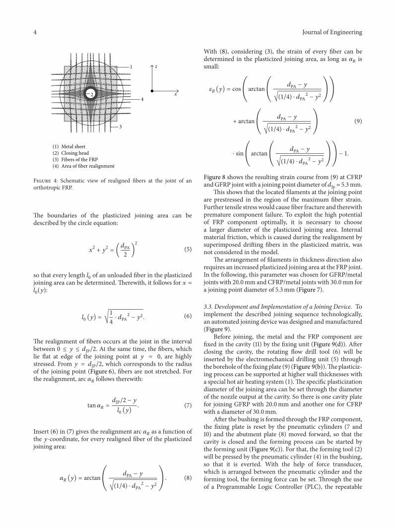
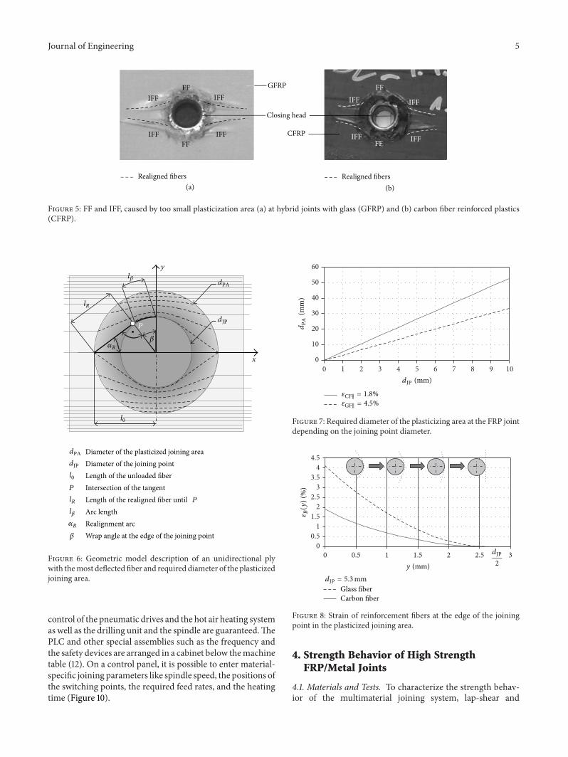
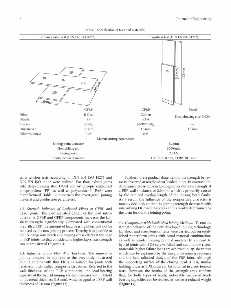
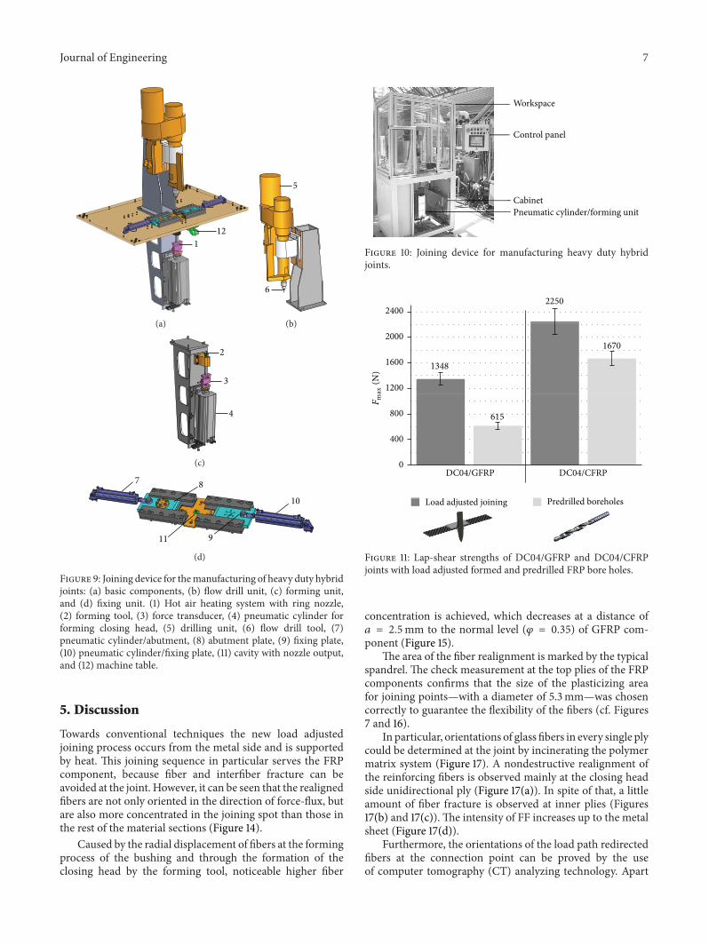
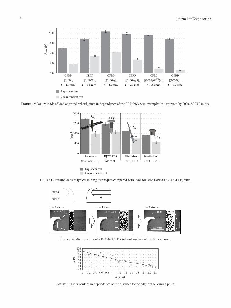
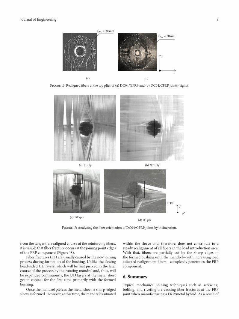
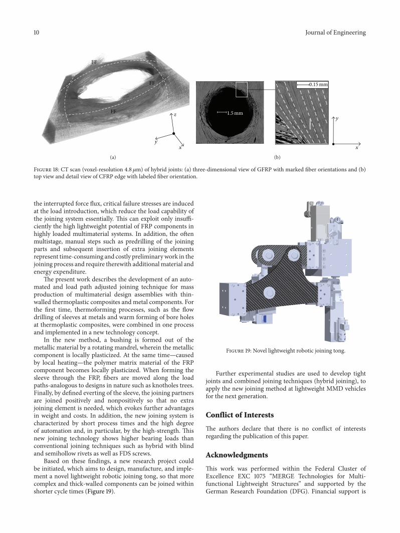
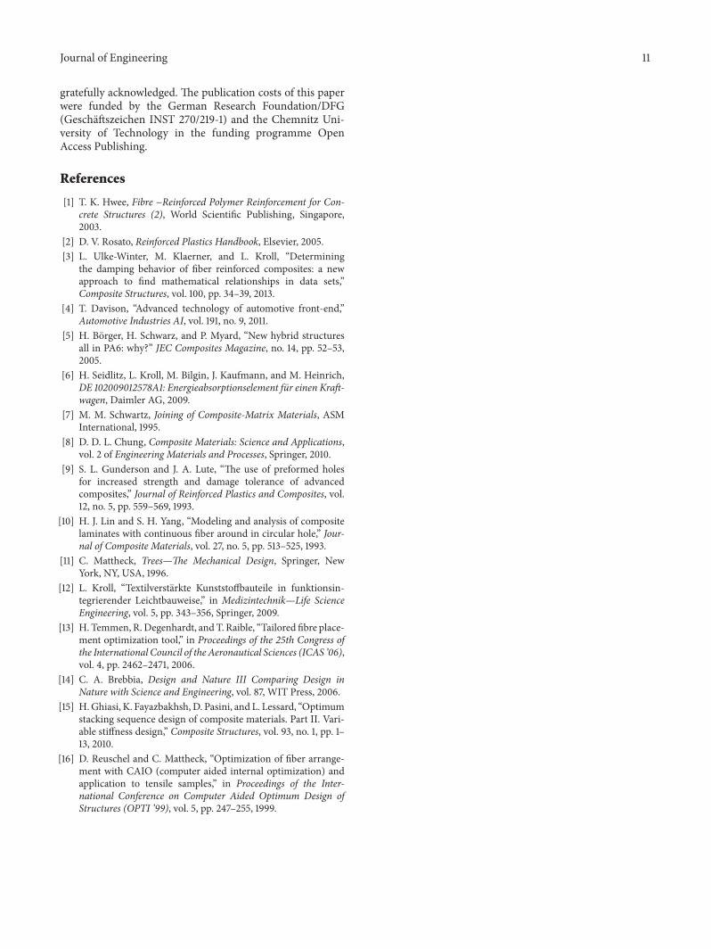

International Journal of
AerospaceEngineeringHindawi Publishing Corporationhttpwwwhindawicom Volume 2014
RoboticsJournal of
Hindawi Publishing Corporationhttpwwwhindawicom Volume 2014
Hindawi Publishing Corporationhttpwwwhindawicom Volume 2014
Active and Passive Electronic Components
Control Scienceand Engineering
Journal of
Hindawi Publishing Corporationhttpwwwhindawicom Volume 2014
International Journal of
RotatingMachinery
Hindawi Publishing Corporationhttpwwwhindawicom Volume 2014
Hindawi Publishing Corporation httpwwwhindawicom
Journal ofEngineeringVolume 2014
Submit your manuscripts athttpwwwhindawicom
VLSI Design
Hindawi Publishing Corporationhttpwwwhindawicom Volume 2014
Hindawi Publishing Corporationhttpwwwhindawicom Volume 2014
Shock and Vibration
Hindawi Publishing Corporationhttpwwwhindawicom Volume 2014
Civil EngineeringAdvances in
Acoustics and VibrationAdvances in
Hindawi Publishing Corporationhttpwwwhindawicom Volume 2014
Hindawi Publishing Corporationhttpwwwhindawicom Volume 2014
Electrical and Computer Engineering
Journal of
Advances inOptoElectronics
Hindawi Publishing Corporation httpwwwhindawicom
Volume 2014
The Scientific World JournalHindawi Publishing Corporation httpwwwhindawicom Volume 2014
SensorsJournal of
Hindawi Publishing Corporationhttpwwwhindawicom Volume 2014
Modelling amp Simulation in EngineeringHindawi Publishing Corporation httpwwwhindawicom Volume 2014
Hindawi Publishing Corporationhttpwwwhindawicom Volume 2014
Chemical EngineeringInternational Journal of Antennas and
Propagation
International Journal of
Hindawi Publishing Corporationhttpwwwhindawicom Volume 2014
Hindawi Publishing Corporationhttpwwwhindawicom Volume 2014
Navigation and Observation
International Journal of
Hindawi Publishing Corporationhttpwwwhindawicom Volume 2014
DistributedSensor Networks
International Journal of