Embed Size (px)
Citation preview
Research ArticleShear Strengthening Performance of Hybrid FRP-FRCM
Kyusan Jung Kinam Hong Sanghoon Han Jaekyu Park and Jaehyun Kim
Department of Civil Engineering Chungbuk National University 1 Chungdae-Ro Seowon-Gu CheongjuChungbuk 362-763 Republic of Korea
Correspondence should be addressed to Kinam Hong hongcbnuackr
Received 28 April 2015 Accepted 8 June 2015
Academic Editor Ana S Guimaraes
Copyright copy 2015 Kyusan Jung et al This is an open access article distributed under the Creative Commons Attribution Licensewhich permits unrestricted use distribution and reproduction in any medium provided the original work is properly cited
The effectiveness of a hybrid fiber reinforced polymer- (FRP-) fabric reinforced cementitious matrix (FRCM) for shear strength-ening was investigated though an experimental study FRP materials of FRCM are usually fabricated in the form of a fabric toenhance the bond strength between the FRP material and the cementitious matrix The hybrid FRP fabric used in this studyconsisted of carbon FRP (CFRP) and glass FRP (GFRP) in warp and weft directions respectively A total of 11 beams were fabricatedand 8 beams among them were strengthened in shear with externally bonded hybrid FRP-FRCM The number of plies the bondtypes and the spacing of the hybrid FRP fabric were considered as experimental variables Additionally a shear capacity model fora FRCM shear strengthened beam was proposed The values predicted by the proposed model were compared with those by theACI 549 code and test results It was confirmed from the comparison that the proposed model predicted the shear strengtheningperformance of the hybrid FRP-FRCMmore reliably than the ACI 549 code did
1 Introduction
FRP has been widely used as a strengthening materialto strengthen deteriorated reinforced concrete (RC) struc-tures all over the world [1] As a strengthening materialFRP possesses excellent material properties including beinglightweight and noncorrosive and providing high tensilestrength [2] On this basis FRP has been applied for strength-ening RC structures in various forms such as sheets platesand strips since the early 1990s [3] Many studies on FRPhave validated the effectiveness of its use as a strengtheningmaterial [4]However FRP is accompanied by several distinctdisadvantages The performance of FRP strengthening forRC structures which may be exposed to sunlight or hightemperature conditions is degraded due to the low glasstransition temperature of epoxy resin a bonding agentFRP strengthening using epoxy resin is also vulnerable tofire Additionally epoxy resin cannot be used under a wetcondition due to its low hardening property
In order to solve these problems a strengthening methodusing a fabric-reinforced cementitious matrix (FRCM) wasdeveloped [5] FRCM consists of FRP fabric and a cemen-titious matrix The mineral cementitious matrix can solve
various problems caused by using epoxy resin as a bond-ing agent FRCM was first introduced as textile reinforcedconcrete (TRC) in a report published by RILEM TechnicalCommittee 201 [6] It has since then been widely reportedon in the literature with various names including textilereinforcedmortar (TRM) [7] fiber reinforced concrete (FRC)[8] and mineral based composites (MBC) [9]
Research using FRCM as a shear strengthening materialhas been performed by researchers worldwide Baggio et alperformed experimental research on RC beams strengthenedin shear with CFRP GFRP FRCM and FRP anchors [10]Theeffectiveness of each material in terms of shear strengtheningwas evaluated and test results were compared with predictedvalues by the Canadian design code Beams strengthenedby using FRCM with and without anchors showed a 31and 34 increase in shear capacity relative to the Controlspecimen respectively The Canadian design code appro-priately predicted the shear capacity of beams strengthenedwith FRP sheets but overestimated those of FRCM strength-ened beams Triantafillou and Papanicolaou carried out anexperimental study to investigate the effectiveness of CFRP-FRCM shear strengthening [7] Although the effectivenessof FRCM shear strengthening was relatively lower than FRP
Hindawi Publishing CorporationAdvances in Materials Science and EngineeringVolume 2015 Article ID 564876 11 pageshttpdxdoiorg1011552015564876
2 Advances in Materials Science and Engineering
shear strengthening the applicability of FRCM as a shearstrengthening material was validated Ombres experimen-tally examined the effectiveness of polyparaphenylene ben-zobisoxazole (PBO) FRCM for shear strengthening [11] Itsshear strengthening performance was predicted by a modelbased on Ritter-Morsch criteria failure He reported that thePBO-FRCM strengthening system significantly improved theshear capacity of reinforced concrete beams and predictionby the model based on the Ritter-Morsch criteria failure iseffective to predict the PBO-FRCM performance Bruckneret al experimentally explored the effectiveness of GFRP-FRCM for shear strengthening [12 13] The number ofGFRP plies the use of mechanical anchors and anchoragemethods were considered as experimental variables in theirstudy Their test results showed that FRCM is effective forshear strengthening and the mechanical anchor improvesthe FRCM shear strengthening performance by 200 Al-Salloum et al also reported that FRCM is effective inincreasing the shear capacity of beams subjected to a four-point load [14] Recently a design code for strengthening RCstructures and masonry walls with externally bonded FRCMwas issued by ACI Committee 549 [15]
Nevertheless the applicability of existing design codesshould be established by experimentally exploring the influ-ence of various experimental parameters such as concretestrength cementitious matrix type and FRP material typeon shear strengthening Experimental research on RC beamsstrengthened in shear with externally bonded FRCM whichwas made from a hybrid fabric and a cementitious matrixwas performed in this study The number of plies the bondtype and the spacing of a hybrid FRP fabric were consideredas experimental variables The effect of test variables onthe shear strengthening capacity was evaluated through testresults and a shear strength prediction model for a hybridFRP-FRCM strengthened beam was proposed The valuespredicted by the proposed model were compared with thoseby ACI 549 [15] and test results
2 Test Program
21 Used Materials Type I ordinary Portland cement (OPC)was used in the mixture Crushed gravel was used asthe coarse aggregate and the maximum aggregate size was25mm In addition AE water-reducing admixture and a vib-rator were used to improve the workability and consolidationof the concrete Table 1 shows the mixture properties of theused concrete
Concrete compressive strength was determined froma compression test for six cylinders with dimensions ofoslash100mm times 200mm according to ASTMC39C39M [18]Theaverage concrete compressive strength was 280MPa at theage of 28 days The mechanical properties of each used rebarwere determined from tension tests for three coupons accord-ing to ASTM A370 [19] and the results are given in Table 2
The cementitious matrix and the hybrid FRP fabric usedfor shear strengthening of RC specimens in this study areshown in Figures 1(a) and 1(b) respectively Cementitiousmatrix consisted of microcement fine aggregate polypropy-lene staple fiber and admixtures The compressive strength
Table 1 Mixture properties of the concrete
WC () Sa () Unit weight (kgm3)W C S G Ad(a)
484 481 168 345 860 949 207(a)AE water-reducing admixture
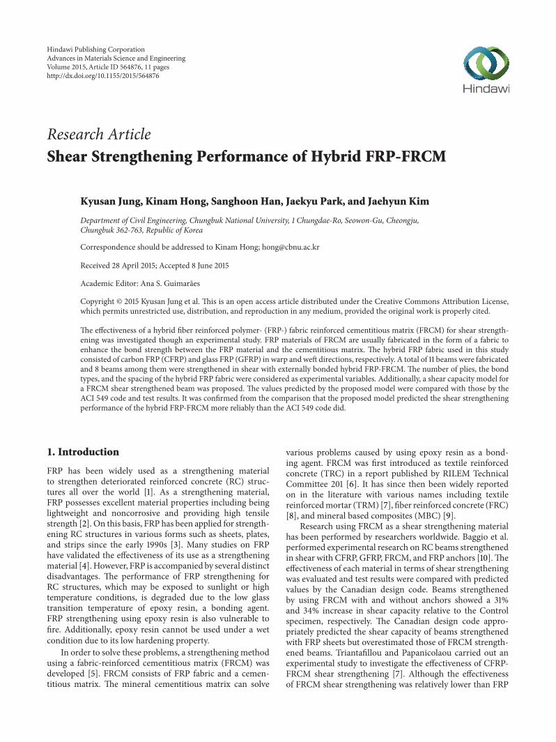
of the cementitious matrix was determined from a compres-sion test for five cubes of 50mm size according to ASTMC109C109M [20] and taken as 45MPa at the age of 28 daysAs shown in Figure 1(b) the hybrid FRP fabric consisted ofCFRP and GFRP strips Black CFRP and white GFRP stripswere laid in the warp direction and weft direction respect-ively at spacing of 17mm and 33mm Mechanical propertiesof the FRCMcompositemade from the hybrid FRP fabric andthe cementitious matrix were determined by a direct tensiletest in accordance with AC 434 [16] as shown in Figure 2Table 3 presents the mechanical properties of the hybrid FRPfabric and the cementitious matrix offered by manufacturersand those of the FRCM composite obtained from the directtensile test
22 Test Variables As shown in Table 4 specimens wereclassified into four groups Specimens in Group I consistedof nonstrengthened specimen and steel stirrup-strengthenedspecimens to evaluate the relative shear-strengthening per-formance of the hybrid FRP-FRCM
The nonstrengthened specimen was designated as Con-trol and the specimens reinforced with steel stirrups atspacing of 200mm and 300mm were denoted by S200 andS300 respectively Specimens in Group II consisted of speci-mens strengthened in shear by side-bonding The specimenswere named according to thewidth and the number of plies ofthe used hybrid FRP fabricThe specimens strengthenedwith1-ply and 2-ply 600mm hybrid FRP fabric were designated asW600-L1 and W600-L2 respectively Specimens in GroupsIII and IV consisted of specimens strengthened by U-jacketing The specimens strengthened by U-jacketing werenamed according to the width and number of plies of hybridFRP fabric For example W50-N5 was strengthened with 5pieces of 50mmwide hybrid FRP fabricThe sixth column ofTable 4 shows hybrid FRP fabric attached on the shear spanaccording to experimental variables
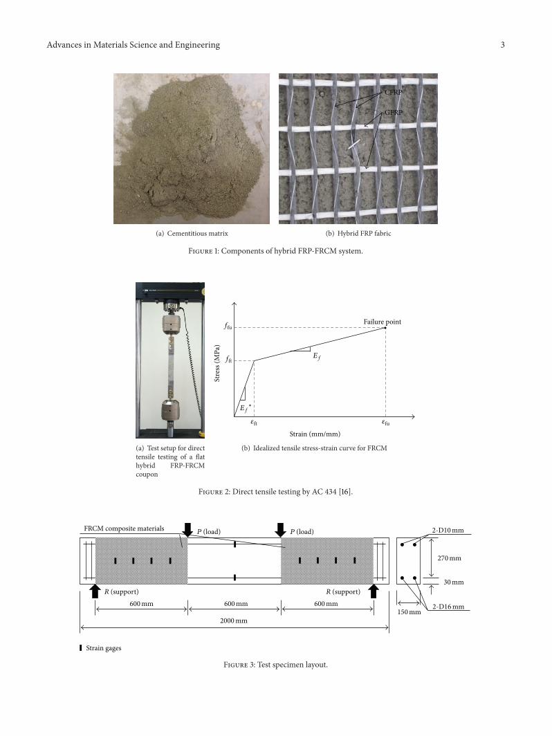
23 Specimen Fabrication and Strengthening As shown inFigure 3 a total of 11 specimens having a length of 2000mmwith a rectangular cross-section 150mm wide and 300mmhigh and a net span of 1800mmwere fabricated for the testsAll specimens were reinforced with two rebars with a nomi-nal diameter of 159mm as tension reinforcement and tworebars with a nominal diameter of 953mm as compressionreinforcement
Specimens S200 and S300 were reinforced by rebars witha nominal diameter of 953mm with spacing of 200mmand 300mm as shear reinforcement respectively After cur-ing of 28 days the shear strengthening specimens werestrengthened with the hybrid FRP-FRCM as follows Firstthe specimen surface was cleaned with tap water to remove
Advances in Materials Science and Engineering 3
(a) Cementitious matrix
CFRP
GFRP
(b) Hybrid FRP fabric
Figure 1 Components of hybrid FRP-FRCM system
(a) Test setup for directtensile testing of a flathybrid FRP-FRCMcoupon
Strain (mmmm)
Stre
ss (M
Pa)
Failure pointffu
fft
Eflowast
Ef
120576ft 120576fu
(b) Idealized tensile stress-strain curve for FRCM
Figure 2 Direct tensile testing by AC 434 [16]
R (support) R (support)
P (load) P (load)
Strain gages
FRCM composite materials
150mm
30mm
2-D10mm
2-D16mm
270mm
600mm 600mm 600mm
2000mm
Figure 3 Test specimen layout
4 Advances in Materials Science and Engineering
Table 2 Mechanical properties of rebar
Nominal diameter(mm)
Modulus of elasticity(MPa)
Yield strength(MPa)
Tensile strength(MPa)
Elongation()
953 20 times 105 480 590 171159 515 610 166
Table 3 Hybrid FRP-FRCMmechanical properties
Nominal thickness Elastic modulus Ultimate tensile strength Ultimate tensile strain Compression strength(mm) (GPa) (MPa) () (MPa)
Hybrid fabric 0107 240 4300 175 mdash
Cementitious matrix mdash 40 mdash mdash 45
FRCM composite mdash 160(cracked specimen)
800 05 mdash
W600-L2
Figure 4 Test setup
impurities before strengthening In order to keep the humidcondition the specimen surface was then covered with dampcloth until strengthening work Specimens strengthened byU-jacketing were reversed and then chamfered to a radius of10mm to avoid damage to the hybrid FRP fabric due to stressconcentration during the tests Specimens were strengthenedwith hybrid FRP-FRCM according to the test variables Thestrengthening procedure of the FRCM composite was asfollows (1) the first layer of cementitious matrix with anominal thickness of 2mmwas applied on the side surface ofthe specimen (2) the precut hybrid FRP fabric was laid on thecementitiousmatrix and (3) the second layer of cementitiousmatrix with a nominal thickness of 2mm was applied onthe hybrid FRP fabric In the case of strengthening with 2-ply hybrid FRP fabric the above procedure was repeatedtwo timesThe nominal thickness of hybrid FRP-FRCMwith1-ply hybrid FRP fabric was taken as approximately 5mmTests were performed after 28 days of strengthening for thecementitious matrix to develop sufficient strength
24 Test Setup The shear tests for 11 specimens were per-formed by four-point loading as shown in Figure 4 Thespecimens were simply supported and the load was appliedat two points 300mm apart at both the left and right sides ofthe midspan The load was applied by stroke control loadingat a rate of 04mmmin with a hydraulic actuator with amax-imum capacity of 2000 kNThe load was measured by a load
cell The vertical displacement at the midspan was measuredby two linear variable differential transformers (LVDTs)
As shown in Figure 3 the strain of the hybrid FRP fabricwas measured by eight strain gauges attached on the CFRPfabric strips at both the left and right sides of the shearspan The CFRP strip of the hybrid FRP fabric was grindedand cleaned with acetone before attachment of strain gaugesLoad and strains were recorded by using a data logger Crackpropagation and FRCM composite damage were visuallymonitored and recorded during all tests
3 Test Results and Discussion
31 Shear Resisting Capacity The test results the maximumload the displacement corresponding to the maximum loadthe gain of the maximum load and the failure mode arepresented in Table 5
The specimen Control failed due to a diagonal shearcrack at the maximum load of 105 kN (see Figure 5(a)) whilespecimens S200 and S300 strengthened with steel stirrupfailed due to the yielding of the tensile steel followed bythe crushing of concrete at maximum load of 168 kN and172 kN respectively (see Figure 5(b)) Specimens W600-L1and W600-L2 strengthened by side-bonding failed due todebonding of the FRCM composite at maximum load of132 kN and 152 kN respectively (see Figure 5(c)) The maxi-mum loads of specimens W600-L1 and W600-L2 increasedby 362 and 448 respectively when compared with theControl specimen Although the maximum load increasedwith an increasing number of plies of hybrid fabric it did notincrease in proportion to the amount of the hybrid fabric
Specimens in Group III failed due to debonding ofthe FRCM composite at the maximum load from 117 kNto 127 kN according to the amount of hybrid FRP fabricThe maximum loads of specimens W50-N4 W50-N5 andW50-N6 increased by 114 171 and 210 relative to theunstrengthened specimen respectively The maximum loadsof specimens W100-N3 and W100-N4 in Group IV were121 kN and 144 kN respectively and their strength increasedby 152 and 371 relative to the unstrengthened specimen
Advances in Materials Science and Engineering 5
Table 4 Test variables
Group Specimen ID Strengthening type Layer Width times number Installation
IControl None None None NoneS300 Steel stirrup None None NoneS200
IIW600-L1
Side-bonding1
600mm times 1W600-L2 2
W50-N4
U-jacketing 1
50mm times 4
III W50-N5 50mm times 5
W50-N6 50mm times 6
W100-N3 100mm times 3
IV W100-N4 100mm times 4
W600-N1 600mm times 1
Table 5 Summary of test results
Specimen ID Maximum load(kN)
Displacement corresponding to maximum load(mm)
Gain of maximum load() Failure mode
Control 105 72 mdash ShearS300 172 202 638 FlexureS200 168 192 600W600-L1 143 83 362
Debonding
W600-L2 152 102 448W50-N4 117 67 114W50-N5 123 53 171W50-N6 127 74 210W100-N3 121 62 152W100-N4 144 86 371W600-N1 162 92 543
Control
(a) Control
S300
(b) S300
W600-L2
(c) W600-L2
W600-N1
(d) W600-N1
Figure 5 Specimens after test
6 Advances in Materials Science and Engineering
20
40
60
80
100
120
140
160
180
Load
(kN
)
Displacement (mm)0 2 4 6 8 10 12 14
ControlS300S200
0
Figure 6 Load-displacement curves of specimens in Group I
respectively All specimens inGroup IV failed due to debond-ing of the FRCM composite similar to specimens in GroupIII The maximum load of specimen W600-N1 was 162 kNand increased by 543 relative to the Control specimen(see Figure 5(d)) The difference in the maximum load ofspecimens W50-N6 and W100-N3 with the same amount ofhybrid FRP fabric was about 6 kN This resulted from thedifference in the spacing of the hybrid FRP with specimensW50-N6 andW100-N3Thedifference in themaximum loadsof W600-L1 and W600-N1 with the same amount of hybridFRP fabric was 30 kN It can be confirmed from this resultthat U-jacketing is more effective than side-bonding
32 Load-Displacement Relationship The load-displacementcurves of specimens in Group I are presented in Figure 6
For the specimen Control the load started to decreasewith the occurrence of diagonal shear cracks at displacementof 44mm and it failed due to a shear crack at displacementof 72mm For specimens S200 and S300 reinforced withsteel stirrups the maximum load increased over that ofspecimenControl and they failed due to the yielding of tensilereinforcement followed by the crushing of concreteThe load-displacement curves of specimens in Group II are shownin Figure 7 This figure shows that specimen W600-L2 hashigher shear capacity and ductility than specimen W600-L1The load-displacement curves of specimens in Group III arepresented in Figure 8
Figure 8 shows that although the load-displacementcurve of specimen W50-N5 is different from those of W50-N4 and W50-N6 the shear capacity increases with a higheramount of hybrid FRP fabric The load-displacement curvesof specimens in Group IV are presented in Figure 9The loadof specimen W100-N3 started to decrease at a displacementof 62mm and it failed due to debonding of the FRCMcomposite at a displacement of 84mm For specimensW100-N4 and W600-N1 although their stiffness decreased at adisplacement of 5mm at which a shear crack of specimen
20
40
60
80
100
120
140
160
180
Load
(kN
)
Displacement (mm)
ControlW600-L1W600-L2
0 2 4 6 8 10 12 140
Figure 7 Load-displacement curves of specimens in Group II
0
20
40
60
80
100
120
140
160
180Lo
ad (k
N)
Displacement (mm)0 2 4 6 8 10 12 14
ControlW50-N4
W50-N5W50-N6
Figure 8 Load-displacement curves of specimens in Group III
Control occurred the load continued to increase In partic-ular the maximum load of specimen W600-N1 was similarto that of specimen S300 Therefore it can be confirmed thatU-jacketing is more effective for FRCM shear strengtheningand hybrid FRP-FRCM is applicable for shear strengtheningof RC beams
33 Strain of Hybrid FRP Fabric Strains of hybrid FRP fabricobtained from specimensW600-L1 andW600-L2 are respec-tively presented in Figure 10The strains weremeasured fromstrain gauges on the hybrid FRP fabric installed at the centerof the shear span The hybrid FRP fabric strain of specimensW600-L1 and W600-L2 did not increase before the initialshear crack occurred The strain of W600-L1 started to moveafter the initial diagonal shear crack and increased sharplyafter a load of 80 kN at which the shear crack was completely
Advances in Materials Science and Engineering 7
0
20
40
60
80
100
120
140
160
180
Load
(kN
)
Displacement (mm)0 2 4 6 8 10 12 14
ControlW100-N3
W100-N4W600-N1
Figure 9 Load-displacement curves of specimens in Group IV
formed The strain of specimen W600-L2 with 2 plies ofhybrid FRP fabric started to increase at a higher load thanspecimen W600-L1 with 1 ply of hybrid FRP fabric Themaximum strains of the hybrid FRP fabric of these specimenswere much smaller than 00175 the strain corresponding torupture of the CFRP fabric stripThis result indicates that thefailure of the specimen strengthened in shear with the hybridFRP-FRCMcomposite is not due to rupture of the hybrid FRPfabric but rather due to debonding between concrete and theFRCM composite
34 Prediction of Shear Capacity
341 ACI Code In order to predict the shear capacity ofbeams strengthened with FRCM ACI Committee 549 [15]has proposed the following equation
119881119899= 119881119888+119881119904+119881119891 (1)
where 119881119899is the nominal shear strength and 119881
119888 119881119904 and 119881
119891
are the contribution of concrete existing steel reinforcementand FRCMcompositematerial to the nominal shear strengthrespectively
The contribution of concrete and steel reinforcement tothe nominal shear strength is calculated according to thefollowing equation proposed by ACI 318 [21]
119881119888= 017radic1198911015840
119888119887119908119889
119881119904=
119860V119891yt119889
119904
(2)
where 1198911015840119888is the specified compressive strength of concrete
119887119908is the web width and 119889 is the distance from the extreme
compression fiber to the centroid of longitudinal tensionreinforcement 119860V is the area of shear reinforcement 119891yt isthe specified yield strength of transverse reinforcement and119904 is the center-to-center spacing of transverse reinforcement
0 200 400 600 800 1000 1200 14000
20
40
60
80
100
120
140
160
Load
(kN
)
Strain (120583120576)
W600-L1W600-L2
Figure 10 Load-strain curves of hybrid FRP-FRCM system
The contribution of FRCM to the nominal shear strengthis calculated according to the following equation proposed byACI 549 [15]
119881119891= 119899119860119891119891119891V119889119891 (3)
where 119899 is the number of layers of mesh reinforcement119860119891is
the area of mesh reinforcement by unit width and 119889119891is the
effective depth of the FRCM shear reinforcementThe design tensile strength of the FRCM composite 119891
119891Vis calculated from the following
119891119891V = 119864119891120576119891V (4)
120576119891V = 120576119891119906 le 0004 (5)
where 119864119891 120576119891V and 120576119891119906 are the tensile modulus of elasticity
of FRCM the design tensile strain of FRCM shear reinforce-ment and the ultimate tensile strain of FRCM respectively
The design tensile strain of the FRCM composite 120576119891V is
limited to 0004 according to ACI 549 [15]
342 Proposed Equation All beams strengthened with thehybrid FRP-FRCM in this study failed due to debondingof the FRCM composite The debonding failure mode isgoverned by the bond strength between the concrete surfaceand the FRCM composite Therefore a prediction modelof the contribution of the FRCM composite to the shearstrength was proposed based on the bond strength betweenthe concrete surface and the hybrid FRP-FRCM in this studyWhen the bond stress at the free end of FRCM reaches theultimate bond stress the distribution of the bond stress at theinterface can be described as in Figure 11 [17]
The average bond stress of side-bonding and U-jacketingcan be calculated from the following equations respectively[22]
120591119901Side-bonding =
int
ℎ1198912minusℎ1198912(4120591ultℎ
2119891) 119909
2119889119909
ℎ
(6)
8 Advances in Materials Science and Engineering
hf
2
minushf
2
h
120591ult
120591p
120591
(a) Side-bonding type
h
hf
120591ult
120591p120591
(b) U-jacketing type
Figure 11 Distribution of shear stress in each strengthening method [17]
120591119901U-jacketing =
int
ℎ119891
0 (120591ultℎ2119891) 119909
2119889119909
ℎ
(7)
where ℎ is the height of the beam ℎ119891
is the height ofthe FRCM composite 120591ult is the ultimate bond stress and120591119901Side-bonding and 120591119901U-jacketing are the average bond stress forside-bonding and U-jacketing respectively
Meanwhile the average bond stress can be expressed asfollows regardless of the FRCM bond type as the ultimatebond stress is the same
120591119901= 120591119901Side-bonding = 120591119901U-jacketing (8)
Therefore the contribution of the hybrid FRP-FRCM to thenominal shear strength can be defined as follows
119881119891= 2119879119891= 2120591119901ℎ119891
119908119891
119908
119889cot120579 (9)
where119879119891is the bond strength of FRCM119889 is the distance from
the extreme compression fiber to the centroid of longitudinaltension reinforcement 120579 is the inclination of the shear crack119908 is the length of the shear span and 119908
119891is the width of the
hybrid FRP fabric bonded on the shear spanIn (9) the average bond stress 120591
119901 was determined from
direct shear tests according to variation of the bond lengthas shown in Figure 12 Bricks with dimensions of 100mmtimes 100mm times 200mm were produced with concrete used inthe beam manufacture process and hybrid FRP-FRCM wasbonded on both sides of the brick in the same manner as thebeams were strengthenedThe average bond stress accordingto the bond length was measured and the test results arepresented in Figure 13 The average bond stress tends todecrease with an increase of bond length until 140mm andthereafter converges to 028MPaTherefore the average shearstress 120591
119901 was defined as 028MPa in the proposed model In
addition the inclination of the shear crack 120579 was defined as45∘ 119881
119888and 119881
119904were calculated by the ACI 318 code [21]
Figure 12 Setup of direct shear test
343 Comparison between Experimental and AnalyticalResults The shear strengths of FRCM shear strengthenedbeams predicted by ACI 549 [15] and the proposedmodel aretabulated in Table 6 Also the ratios of the test results to theshear strengths predicted by ACI 549 [15] and the proposedmodel are presented in Table 6
The ratios by ACI 549 [15] for specimens W600-L1 andW600-L2 strengthened by side-bonding were 098 and 069respectively It can be confirmed from these results that ACI549 [15] overestimates the shear strength of FRCM shearstrengthened beams by side-bonding and the prediction errorincreases with an increase of the amount of hybrid FRP Incontrast the ratios by ACI 549 [15] for shear strengthenedbeams by U-jacketing ranged from 110 to 122 NamelyACI 549 [15] underestimates the shear strength of shearstrengthened beams by U-jacketing
The ratios by the predicted model for specimens W600-L1 and W600-L2 strengthened by side-bonding were 088and 094 respectively Although the proposed model also
Advances in Materials Science and Engineering 9
Table 6 Comparisons between predicted values and experimental results
Specimen ID 119875EXP(kN)
ACI 549 [15] Proposed model119881119888
119881119904119881FRCM 119875ACI
119875EXP119875ACI119881119888
119881119904119881FRCM 119875Prop
119875EXP119875Prop(kN) (kN) (kN) (kN) (kN) (kN) (kN) (kN)
Control 105
36
mdash mdash 72 146 mdash mdash 72 146S300 172 51 mdash 174 099 51 mdash 174 099S200 168 77 mdash 226 074 77 mdash 226 074W600-L1 143 mdash 37 146 098 mdash 45 162 088W600-L2 152 mdash 74 220 069 mdash 45 162 094W50-N4 117 mdash 12 96 122 36 mdash 15 102 115W50-N5 123 mdash 15 102 121 mdash 19 110 112W50-N6 127 mdash 19 110 115 mdash 23 118 108W100-N3 121 mdash 19 110 110 mdash 23 118 103W100-N4 144 mdash 25 122 118 mdash 30 132 109W600-N1 162 mdash 37 146 111 mdash 45 162 100Mean 108 104
0 20 40 60 80 100 120 140 160 180 20000
01
02
03
04
05
06
07
08
Aver
age b
ond
stres
s (M
Pa)
Bond length (mm)
Figure 13 Average bond stress according to bond length
overestimates the shear strength of the beams strengthenedby side-bonding the prediction error was smaller than that ofthe ACI 549 code [15] Moreover the ratios by the proposedmodel for the shear strengthened beams by U-jacketingranged from 100 to 115 which are smaller than those givenby the ACI 549 code [15] This validates that the proposedmodel predicted the shear strength of beams strengthened byU-jacketing more reliably than ACI 549 [15] did
344 Comparison between the Proposed Model and Exist-ing Experimental Results The performance of the proposedmodel was evaluated through a comparison between thenumerically predicted values and existing experimentalresults [4 10 11 14] The geometry and material propertiesof RC beam specimens of the existing tests are presentedin Table 7 Table 8 shows comparisons between the pro-posed model and existing experimental results ACI 549 [15]requires the tensilemodulus of elasticity for the FRCMwhich
is obtained from direct tensile test for the FRCM to calculatethe shear capacity of FRCM strengthened beams Howeverthe references in Table 7 did not present the tensile modulusof elasticity for the FRCM Thus the comparison betweenACI 549 [15] and the existing experimental results has beenexcluded in the present study
From Table 8 it can be confirmed that the proposedmodel predicts the existing experimental results well themean of the ratio between the proposed model and corre-sponding experimental results is 099 and its coefficient vari-able (COV) is 016 Accordingly it can be concluded that theshear prediction model from this study could be widely usedfor shear capacity estimation of FRCM strengthened beams
4 Conclusion
Conclusions obtained from this study are as follows
(1) It was validated that the maximum load of shearstrengthened beams with hybrid FRP-FRCM in-creased from 114 to 543 according to the amountof hybrid FRP and the effectiveness of hybrid FRP forshear capacity is not proportional to the amount used
(2) It was confirmed from test results that U-jacketingwasmore effective than side-bonding for FRCMshearstrengthening
(3) ACI 549 [15] overestimated the shear strength ofbeams strengthened by side-bonding with hybridFRP-FRCM and the prediction error increases withan increase of the amount of hybrid FRP In additionACI 549 [15] underestimated the shear strength ofshear strengthened beams by U-jacketing
(4) Although the proposed model also overestimatedthe shear strength of beams strengthened by side-bondingwith hybrid FRP-FRCM the prediction errorwas smaller than that of ACI 549 [15] Moreoverfor shear-strengthened beams by U-jacketing the
10 Advances in Materials Science and Engineering
Table 7 Geometry and material properties of RC beam specimens of experimental test database
Reference Specimen ID 119887 119889 ℎ119891
1198911015840
119888119860V 119891
119910119905119904 119908 119908
119891119886119889
(mm) (mm) (mm) (MPa) (mm2) (MPa) (mm) (mm) (mm)
[4]
SB-GT 150 3075 350 375 mdash mdash mdash 1000 1000 325UW-GT 150 3075 350 375 mdash mdash mdash 1000 1000 325SB-CT1 150 3075 350 375 mdash mdash mdash 1000 1000 325UW-CT1 150 3075 350 375 mdash mdash mdash 1000 1000 325SB-CT2 150 3075 350 375 mdash mdash mdash 1000 1000 325UW-CT2 150 3075 350 375 mdash mdash mdash 1000 1000 325
[10] Beam 4 150 295 350 501 5655 384 180 900 675 305
[11]
TRA1 150 225 250 3076 10053 44606 292 675 675 300TRA2 150 225 250 3076 10053 44606 260 675 345 300TRB1 150 225 250 4502 10053 44225 210 625 625 278TRB2 150 225 250 2916 10053 44225 210 625 625 278TRB3 150 225 250 2916 10053 44225 210 625 295 278TRB4 150 225 250 3826 10053 44225 210 625 295 278TRB5 150 225 250 3826 10053 44225 210 625 295 278
[14]
BS2 150 175 200 20 mdash mdash mdash 400 400 229BS3 150 175 200 20 mdash mdash mdash 400 400 229BS4 150 175 200 20 mdash mdash mdash 400 400 229BS5 150 175 200 20 mdash mdash mdash 400 400 229
Table 8 Comparisons between the existing experimental results and proposed model
Reference Specimen ID Type of bond Type of fiber 120588119891
119875Exp 119881119888
119881119904119881FRCM 119875Prop
119875Exp119875Prop() (kN) (kN) (kN) (kN) (kN)
[4]
SB-GT S G 0297 1463 4802 mdash 6027 2166 068UW-GT U G 0297 1802 4802 mdash 6027 2166 083SB-CT1 S C 0229 1555 4802 mdash 6027 2166 072UW-CT1 U C 0229 1518 4802 mdash 6027 2166 070SB-CT2 S C 0516 2454 4802 mdash 6027 2166 113UW-CT2 U C 0516 2534 4802 mdash 6027 2166 117
[10] Beam 4 U G 0096 2940 5325 3559 4337 2644 111
[11]
TRA1 S P 0135 1887 3182 3455 3147 1957 096TRA2 U P 0034 1704 3182 3881 1610 1735 098TRB1 S P 0202 2791 3182 3881 4702 2353 119TRB2 S P 0202 1917 3182 3881 3947 2202 087TRB3 U P 0095 1919 3182 3881 2287 1870 103TRB4 U P 0095 2000 3182 3881 2737 1960 102TRB5 U P 0095 1998 3182 3881 2737 1960 102
[14]
BS2 S B 0195 827 1996 mdash 196 791 105BS3 S B 0195 835 1996 mdash 196 791 106BS4 S B 0390 887 1996 mdash 196 791 112BS5 S B 0390 925 1996 mdash 196 791 117
Mean 099Coefficient of variation 016
Note S = side-bonding U = U-jacketing G = glass C = carbon P = PBO B = basalt
Advances in Materials Science and Engineering 11
proposed model predicted the shear strength morereliably than ACI 549 [15] did
(5) The agreement between the proposed model and theexisting experimental results was very good Accord-ingly it can be concluded that the shear predictionmodel from this study could be widely used for shearcapacity estimation of FRCM strengthened beams
Conflict of Interests
The authors declare that there is no conflict of interestsregarding the publication of this paper
Acknowledgment
This work (Grant no C0135751) was supported by Busi-ness for Cooperative RampD between Industry Academy andResearch Institute funded by Korea Small and MediumBusiness Administration in 2013
References
[1] L C Hollaway and M B Leeming Strengthening of ReinforcedConcrete Structures Using Externally-Bonded FRP Composites inStructural and Civil Engineering Woodhead Publishing Cam-bridge UK 1999
[2] A DrsquoAmbrisi and F Focacci ldquoFlexural strengthening of RCbeams with cement-based compositesrdquo Journal of Compositesfor Construction vol 15 no 5 pp 707ndash720 2011
[3] G Loreto L Leardini D Arboleda and A Nanni ldquoPerfor-mance of RC slab-type elements strengthened with fabric-rein-forced cementitious-matrix compositesrdquo Journal of Compositesfor Construction vol 18 no 3 Article ID A4013003 2014
[4] R Azam and K Soudki ldquoFRCM strengthening of shear-criticalRC beamsrdquo Journal of Composites for Construction vol 18 no5 2014
[5] S Babaeidarabad G Loreto and A Nanni ldquoFlexural strength-ening of RC beams with an externally bonded fabric-reinforcedcementitious matrixrdquo Journal of Composites for Constructionvol 18 no 5 2014
[6] W Brameshuber T Brockmann M Curbach et al ldquoState of theart report 36 textile reinforced concreterdquo RILEM TC 201-TRCRILEM 2006
[7] T C Triantafillou andCG Papanicolaou ldquoShear strengtheningof reinforced concrete members with textile reinforced mortar(TRM) jacketsrdquo Materials and Structures vol 39 no 285 pp93ndash103 2006
[8] H CWu and P Sun ldquoFiber reinforced cement based compositesheets for structural retrofitrdquo in Proceedings of the InternationalSymposium in Bond Behaviour of FRP in Structures (BBFS rsquo05)pp 351ndash356 International Institute for FRP in ConstructionHong Kong China 2005
[9] T Blanksvard B Taljsten and A Carolin ldquoShear strengtheningof concrete structures with the use of mineral-based compos-itesrdquo Journal of Composites for Construction vol 13 no 1 pp25ndash34 2009
[10] D Baggio K Soudki andM Noel ldquoStrengthening of shear cri-tical RC beams with various FRP systemsrdquo Construction andBuilding Materials vol 66 pp 634ndash644 2014
[11] L Ombres ldquoStructural performances of reinforced concretebeams strengthened in shear with a cement based fiber compos-ite materialrdquo Composite Structures vol 122 pp 316ndash329 2015
[12] A Bruckner R Ortlepp and M Curbach ldquoAnchoring of shearstrengthening for T-beams made of textile reinforced concrete(TRC)rdquo Materials and Structures vol 41 no 2 pp 407ndash4182008
[13] A Bruckner R Ortlepp and M Curbach ldquoTextile reinforcedconcrete for strengthening in bending and shearrdquoMaterials andStructures vol 39 no 292 pp 741ndash748 2006
[14] Y A Al-Salloum H M Elsanadedy S H Alsayed and RA Iqbal ldquoExperimental and numerical study for the shearstrengthening of reinforced concrete beams using textile-reinforced mortarrdquo Journal of Composites for Construction vol16 no 1 pp 74ndash90 2012
[15] American Concrete Institute (ACI) ldquoDesign and constructionguide of externally bonded FRCM systems for concrete andmasonry repair and strengtheningrdquo ACI 549 American Con-crete Institute Farmington Hills Mich USA 2013
[16] ICC Evaluation Service ldquoAcceptance criteria for masonry andconcrete strengthening using fiber reinforced cementitiousmatrix (FRCM) composite systemsrdquo Tech Rep AC434 ICCEvaluation Service Whittier Calif USA 2013
[17] G J Al-Sulaimani A Sharif I A Basunbul M H Baluch andB N Ghaleb ldquoShear repair for reinforced concrete by fiberglassplate bondingrdquo ACI Structural Journal vol 91 no 4 pp 458ndash464 1994
[18] ASTM International ldquoStandard test method for compressivestrength of cylindrical concrete specimensrdquo Tech Rep C39C39M ASTM International West Conshohocken Pa USA2013
[19] ASTM ldquoStandard test methods and definitions for mechanicaltesting of steel productsrdquo A370 ASTM West ConshohockenPa USA 2013
[20] ASTM ldquoStandard test method for compressive strength ofhydraulic cement mortarsrdquo ASTM C109C109M ASTM WestConshohocken Pa USA 2013
[21] American Concrete Institute (ACI) ldquoBuilding code require-ments for reinforced concreterdquo ACI 318 American ConcreteInstitute Farmington Hills Mich USA 2011
[22] J S SimH SOh and JMYu ldquoA study on the predictionmodelof shear strength of RC beams strengthened for shear by FRPrdquoJournal of the Korea Concrete Institute vol 12 no 5 pp 35ndash462000 (Korean)
Submit your manuscripts athttpwwwhindawicom
ScientificaHindawi Publishing Corporationhttpwwwhindawicom Volume 2014
CorrosionInternational Journal of
Hindawi Publishing Corporationhttpwwwhindawicom Volume 2014
Polymer ScienceInternational Journal of
Hindawi Publishing Corporationhttpwwwhindawicom Volume 2014
Hindawi Publishing Corporationhttpwwwhindawicom Volume 2014
CeramicsJournal of
Hindawi Publishing Corporationhttpwwwhindawicom Volume 2014
CompositesJournal of
NanoparticlesJournal of
Hindawi Publishing Corporationhttpwwwhindawicom Volume 2014
Hindawi Publishing Corporationhttpwwwhindawicom Volume 2014
International Journal of
Biomaterials
Hindawi Publishing Corporationhttpwwwhindawicom Volume 2014
NanoscienceJournal of
TextilesHindawi Publishing Corporation httpwwwhindawicom Volume 2014
Journal of
NanotechnologyHindawi Publishing Corporationhttpwwwhindawicom Volume 2014
Journal of
CrystallographyJournal of
Hindawi Publishing Corporationhttpwwwhindawicom Volume 2014
The Scientific World JournalHindawi Publishing Corporation httpwwwhindawicom Volume 2014
Hindawi Publishing Corporationhttpwwwhindawicom Volume 2014
CoatingsJournal of
Advances in
Materials Science and EngineeringHindawi Publishing Corporationhttpwwwhindawicom Volume 2014
Smart Materials Research
Hindawi Publishing Corporationhttpwwwhindawicom Volume 2014
Hindawi Publishing Corporationhttpwwwhindawicom Volume 2014
MetallurgyJournal of
Hindawi Publishing Corporationhttpwwwhindawicom Volume 2014
BioMed Research International
MaterialsJournal of
Hindawi Publishing Corporationhttpwwwhindawicom Volume 2014
Nano
materials
Hindawi Publishing Corporationhttpwwwhindawicom Volume 2014
Journal ofNanomaterials

2 Advances in Materials Science and Engineering
shear strengthening the applicability of FRCM as a shearstrengthening material was validated Ombres experimen-tally examined the effectiveness of polyparaphenylene ben-zobisoxazole (PBO) FRCM for shear strengthening [11] Itsshear strengthening performance was predicted by a modelbased on Ritter-Morsch criteria failure He reported that thePBO-FRCM strengthening system significantly improved theshear capacity of reinforced concrete beams and predictionby the model based on the Ritter-Morsch criteria failure iseffective to predict the PBO-FRCM performance Bruckneret al experimentally explored the effectiveness of GFRP-FRCM for shear strengthening [12 13] The number ofGFRP plies the use of mechanical anchors and anchoragemethods were considered as experimental variables in theirstudy Their test results showed that FRCM is effective forshear strengthening and the mechanical anchor improvesthe FRCM shear strengthening performance by 200 Al-Salloum et al also reported that FRCM is effective inincreasing the shear capacity of beams subjected to a four-point load [14] Recently a design code for strengthening RCstructures and masonry walls with externally bonded FRCMwas issued by ACI Committee 549 [15]
Nevertheless the applicability of existing design codesshould be established by experimentally exploring the influ-ence of various experimental parameters such as concretestrength cementitious matrix type and FRP material typeon shear strengthening Experimental research on RC beamsstrengthened in shear with externally bonded FRCM whichwas made from a hybrid fabric and a cementitious matrixwas performed in this study The number of plies the bondtype and the spacing of a hybrid FRP fabric were consideredas experimental variables The effect of test variables onthe shear strengthening capacity was evaluated through testresults and a shear strength prediction model for a hybridFRP-FRCM strengthened beam was proposed The valuespredicted by the proposed model were compared with thoseby ACI 549 [15] and test results
2 Test Program
21 Used Materials Type I ordinary Portland cement (OPC)was used in the mixture Crushed gravel was used asthe coarse aggregate and the maximum aggregate size was25mm In addition AE water-reducing admixture and a vib-rator were used to improve the workability and consolidationof the concrete Table 1 shows the mixture properties of theused concrete
Concrete compressive strength was determined froma compression test for six cylinders with dimensions ofoslash100mm times 200mm according to ASTMC39C39M [18]Theaverage concrete compressive strength was 280MPa at theage of 28 days The mechanical properties of each used rebarwere determined from tension tests for three coupons accord-ing to ASTM A370 [19] and the results are given in Table 2
The cementitious matrix and the hybrid FRP fabric usedfor shear strengthening of RC specimens in this study areshown in Figures 1(a) and 1(b) respectively Cementitiousmatrix consisted of microcement fine aggregate polypropy-lene staple fiber and admixtures The compressive strength
Table 1 Mixture properties of the concrete
WC () Sa () Unit weight (kgm3)W C S G Ad(a)
484 481 168 345 860 949 207(a)AE water-reducing admixture
of the cementitious matrix was determined from a compres-sion test for five cubes of 50mm size according to ASTMC109C109M [20] and taken as 45MPa at the age of 28 daysAs shown in Figure 1(b) the hybrid FRP fabric consisted ofCFRP and GFRP strips Black CFRP and white GFRP stripswere laid in the warp direction and weft direction respect-ively at spacing of 17mm and 33mm Mechanical propertiesof the FRCMcompositemade from the hybrid FRP fabric andthe cementitious matrix were determined by a direct tensiletest in accordance with AC 434 [16] as shown in Figure 2Table 3 presents the mechanical properties of the hybrid FRPfabric and the cementitious matrix offered by manufacturersand those of the FRCM composite obtained from the directtensile test
22 Test Variables As shown in Table 4 specimens wereclassified into four groups Specimens in Group I consistedof nonstrengthened specimen and steel stirrup-strengthenedspecimens to evaluate the relative shear-strengthening per-formance of the hybrid FRP-FRCM
The nonstrengthened specimen was designated as Con-trol and the specimens reinforced with steel stirrups atspacing of 200mm and 300mm were denoted by S200 andS300 respectively Specimens in Group II consisted of speci-mens strengthened in shear by side-bonding The specimenswere named according to thewidth and the number of plies ofthe used hybrid FRP fabricThe specimens strengthenedwith1-ply and 2-ply 600mm hybrid FRP fabric were designated asW600-L1 and W600-L2 respectively Specimens in GroupsIII and IV consisted of specimens strengthened by U-jacketing The specimens strengthened by U-jacketing werenamed according to the width and number of plies of hybridFRP fabric For example W50-N5 was strengthened with 5pieces of 50mmwide hybrid FRP fabricThe sixth column ofTable 4 shows hybrid FRP fabric attached on the shear spanaccording to experimental variables
23 Specimen Fabrication and Strengthening As shown inFigure 3 a total of 11 specimens having a length of 2000mmwith a rectangular cross-section 150mm wide and 300mmhigh and a net span of 1800mmwere fabricated for the testsAll specimens were reinforced with two rebars with a nomi-nal diameter of 159mm as tension reinforcement and tworebars with a nominal diameter of 953mm as compressionreinforcement
Specimens S200 and S300 were reinforced by rebars witha nominal diameter of 953mm with spacing of 200mmand 300mm as shear reinforcement respectively After cur-ing of 28 days the shear strengthening specimens werestrengthened with the hybrid FRP-FRCM as follows Firstthe specimen surface was cleaned with tap water to remove
Advances in Materials Science and Engineering 3
(a) Cementitious matrix
CFRP
GFRP
(b) Hybrid FRP fabric
Figure 1 Components of hybrid FRP-FRCM system
(a) Test setup for directtensile testing of a flathybrid FRP-FRCMcoupon
Strain (mmmm)
Stre
ss (M
Pa)
Failure pointffu
fft
Eflowast
Ef
120576ft 120576fu
(b) Idealized tensile stress-strain curve for FRCM
Figure 2 Direct tensile testing by AC 434 [16]
R (support) R (support)
P (load) P (load)
Strain gages
FRCM composite materials
150mm
30mm
2-D10mm
2-D16mm
270mm
600mm 600mm 600mm
2000mm
Figure 3 Test specimen layout
4 Advances in Materials Science and Engineering
Table 2 Mechanical properties of rebar
Nominal diameter(mm)
Modulus of elasticity(MPa)
Yield strength(MPa)
Tensile strength(MPa)
Elongation()
953 20 times 105 480 590 171159 515 610 166
Table 3 Hybrid FRP-FRCMmechanical properties
Nominal thickness Elastic modulus Ultimate tensile strength Ultimate tensile strain Compression strength(mm) (GPa) (MPa) () (MPa)
Hybrid fabric 0107 240 4300 175 mdash
Cementitious matrix mdash 40 mdash mdash 45
FRCM composite mdash 160(cracked specimen)
800 05 mdash
W600-L2
Figure 4 Test setup
impurities before strengthening In order to keep the humidcondition the specimen surface was then covered with dampcloth until strengthening work Specimens strengthened byU-jacketing were reversed and then chamfered to a radius of10mm to avoid damage to the hybrid FRP fabric due to stressconcentration during the tests Specimens were strengthenedwith hybrid FRP-FRCM according to the test variables Thestrengthening procedure of the FRCM composite was asfollows (1) the first layer of cementitious matrix with anominal thickness of 2mmwas applied on the side surface ofthe specimen (2) the precut hybrid FRP fabric was laid on thecementitiousmatrix and (3) the second layer of cementitiousmatrix with a nominal thickness of 2mm was applied onthe hybrid FRP fabric In the case of strengthening with 2-ply hybrid FRP fabric the above procedure was repeatedtwo timesThe nominal thickness of hybrid FRP-FRCMwith1-ply hybrid FRP fabric was taken as approximately 5mmTests were performed after 28 days of strengthening for thecementitious matrix to develop sufficient strength
24 Test Setup The shear tests for 11 specimens were per-formed by four-point loading as shown in Figure 4 Thespecimens were simply supported and the load was appliedat two points 300mm apart at both the left and right sides ofthe midspan The load was applied by stroke control loadingat a rate of 04mmmin with a hydraulic actuator with amax-imum capacity of 2000 kNThe load was measured by a load
cell The vertical displacement at the midspan was measuredby two linear variable differential transformers (LVDTs)
As shown in Figure 3 the strain of the hybrid FRP fabricwas measured by eight strain gauges attached on the CFRPfabric strips at both the left and right sides of the shearspan The CFRP strip of the hybrid FRP fabric was grindedand cleaned with acetone before attachment of strain gaugesLoad and strains were recorded by using a data logger Crackpropagation and FRCM composite damage were visuallymonitored and recorded during all tests
3 Test Results and Discussion
31 Shear Resisting Capacity The test results the maximumload the displacement corresponding to the maximum loadthe gain of the maximum load and the failure mode arepresented in Table 5
The specimen Control failed due to a diagonal shearcrack at the maximum load of 105 kN (see Figure 5(a)) whilespecimens S200 and S300 strengthened with steel stirrupfailed due to the yielding of the tensile steel followed bythe crushing of concrete at maximum load of 168 kN and172 kN respectively (see Figure 5(b)) Specimens W600-L1and W600-L2 strengthened by side-bonding failed due todebonding of the FRCM composite at maximum load of132 kN and 152 kN respectively (see Figure 5(c)) The maxi-mum loads of specimens W600-L1 and W600-L2 increasedby 362 and 448 respectively when compared with theControl specimen Although the maximum load increasedwith an increasing number of plies of hybrid fabric it did notincrease in proportion to the amount of the hybrid fabric
Specimens in Group III failed due to debonding ofthe FRCM composite at the maximum load from 117 kNto 127 kN according to the amount of hybrid FRP fabricThe maximum loads of specimens W50-N4 W50-N5 andW50-N6 increased by 114 171 and 210 relative to theunstrengthened specimen respectively The maximum loadsof specimens W100-N3 and W100-N4 in Group IV were121 kN and 144 kN respectively and their strength increasedby 152 and 371 relative to the unstrengthened specimen
Advances in Materials Science and Engineering 5
Table 4 Test variables
Group Specimen ID Strengthening type Layer Width times number Installation
IControl None None None NoneS300 Steel stirrup None None NoneS200
IIW600-L1
Side-bonding1
600mm times 1W600-L2 2
W50-N4
U-jacketing 1
50mm times 4
III W50-N5 50mm times 5
W50-N6 50mm times 6
W100-N3 100mm times 3
IV W100-N4 100mm times 4
W600-N1 600mm times 1
Table 5 Summary of test results
Specimen ID Maximum load(kN)
Displacement corresponding to maximum load(mm)
Gain of maximum load() Failure mode
Control 105 72 mdash ShearS300 172 202 638 FlexureS200 168 192 600W600-L1 143 83 362
Debonding
W600-L2 152 102 448W50-N4 117 67 114W50-N5 123 53 171W50-N6 127 74 210W100-N3 121 62 152W100-N4 144 86 371W600-N1 162 92 543
Control
(a) Control
S300
(b) S300
W600-L2
(c) W600-L2
W600-N1
(d) W600-N1
Figure 5 Specimens after test
6 Advances in Materials Science and Engineering
20
40
60
80
100
120
140
160
180
Load
(kN
)
Displacement (mm)0 2 4 6 8 10 12 14
ControlS300S200
0
Figure 6 Load-displacement curves of specimens in Group I
respectively All specimens inGroup IV failed due to debond-ing of the FRCM composite similar to specimens in GroupIII The maximum load of specimen W600-N1 was 162 kNand increased by 543 relative to the Control specimen(see Figure 5(d)) The difference in the maximum load ofspecimens W50-N6 and W100-N3 with the same amount ofhybrid FRP fabric was about 6 kN This resulted from thedifference in the spacing of the hybrid FRP with specimensW50-N6 andW100-N3Thedifference in themaximum loadsof W600-L1 and W600-N1 with the same amount of hybridFRP fabric was 30 kN It can be confirmed from this resultthat U-jacketing is more effective than side-bonding
32 Load-Displacement Relationship The load-displacementcurves of specimens in Group I are presented in Figure 6
For the specimen Control the load started to decreasewith the occurrence of diagonal shear cracks at displacementof 44mm and it failed due to a shear crack at displacementof 72mm For specimens S200 and S300 reinforced withsteel stirrups the maximum load increased over that ofspecimenControl and they failed due to the yielding of tensilereinforcement followed by the crushing of concreteThe load-displacement curves of specimens in Group II are shownin Figure 7 This figure shows that specimen W600-L2 hashigher shear capacity and ductility than specimen W600-L1The load-displacement curves of specimens in Group III arepresented in Figure 8
Figure 8 shows that although the load-displacementcurve of specimen W50-N5 is different from those of W50-N4 and W50-N6 the shear capacity increases with a higheramount of hybrid FRP fabric The load-displacement curvesof specimens in Group IV are presented in Figure 9The loadof specimen W100-N3 started to decrease at a displacementof 62mm and it failed due to debonding of the FRCMcomposite at a displacement of 84mm For specimensW100-N4 and W600-N1 although their stiffness decreased at adisplacement of 5mm at which a shear crack of specimen
20
40
60
80
100
120
140
160
180
Load
(kN
)
Displacement (mm)
ControlW600-L1W600-L2
0 2 4 6 8 10 12 140
Figure 7 Load-displacement curves of specimens in Group II
0
20
40
60
80
100
120
140
160
180Lo
ad (k
N)
Displacement (mm)0 2 4 6 8 10 12 14
ControlW50-N4
W50-N5W50-N6
Figure 8 Load-displacement curves of specimens in Group III
Control occurred the load continued to increase In partic-ular the maximum load of specimen W600-N1 was similarto that of specimen S300 Therefore it can be confirmed thatU-jacketing is more effective for FRCM shear strengtheningand hybrid FRP-FRCM is applicable for shear strengtheningof RC beams
33 Strain of Hybrid FRP Fabric Strains of hybrid FRP fabricobtained from specimensW600-L1 andW600-L2 are respec-tively presented in Figure 10The strains weremeasured fromstrain gauges on the hybrid FRP fabric installed at the centerof the shear span The hybrid FRP fabric strain of specimensW600-L1 and W600-L2 did not increase before the initialshear crack occurred The strain of W600-L1 started to moveafter the initial diagonal shear crack and increased sharplyafter a load of 80 kN at which the shear crack was completely
Advances in Materials Science and Engineering 7
0
20
40
60
80
100
120
140
160
180
Load
(kN
)
Displacement (mm)0 2 4 6 8 10 12 14
ControlW100-N3
W100-N4W600-N1
Figure 9 Load-displacement curves of specimens in Group IV
formed The strain of specimen W600-L2 with 2 plies ofhybrid FRP fabric started to increase at a higher load thanspecimen W600-L1 with 1 ply of hybrid FRP fabric Themaximum strains of the hybrid FRP fabric of these specimenswere much smaller than 00175 the strain corresponding torupture of the CFRP fabric stripThis result indicates that thefailure of the specimen strengthened in shear with the hybridFRP-FRCMcomposite is not due to rupture of the hybrid FRPfabric but rather due to debonding between concrete and theFRCM composite
34 Prediction of Shear Capacity
341 ACI Code In order to predict the shear capacity ofbeams strengthened with FRCM ACI Committee 549 [15]has proposed the following equation
119881119899= 119881119888+119881119904+119881119891 (1)
where 119881119899is the nominal shear strength and 119881
119888 119881119904 and 119881
119891
are the contribution of concrete existing steel reinforcementand FRCMcompositematerial to the nominal shear strengthrespectively
The contribution of concrete and steel reinforcement tothe nominal shear strength is calculated according to thefollowing equation proposed by ACI 318 [21]
119881119888= 017radic1198911015840
119888119887119908119889
119881119904=
119860V119891yt119889
119904
(2)
where 1198911015840119888is the specified compressive strength of concrete
119887119908is the web width and 119889 is the distance from the extreme
compression fiber to the centroid of longitudinal tensionreinforcement 119860V is the area of shear reinforcement 119891yt isthe specified yield strength of transverse reinforcement and119904 is the center-to-center spacing of transverse reinforcement
0 200 400 600 800 1000 1200 14000
20
40
60
80
100
120
140
160
Load
(kN
)
Strain (120583120576)
W600-L1W600-L2
Figure 10 Load-strain curves of hybrid FRP-FRCM system
The contribution of FRCM to the nominal shear strengthis calculated according to the following equation proposed byACI 549 [15]
119881119891= 119899119860119891119891119891V119889119891 (3)
where 119899 is the number of layers of mesh reinforcement119860119891is
the area of mesh reinforcement by unit width and 119889119891is the
effective depth of the FRCM shear reinforcementThe design tensile strength of the FRCM composite 119891
119891Vis calculated from the following
119891119891V = 119864119891120576119891V (4)
120576119891V = 120576119891119906 le 0004 (5)
where 119864119891 120576119891V and 120576119891119906 are the tensile modulus of elasticity
of FRCM the design tensile strain of FRCM shear reinforce-ment and the ultimate tensile strain of FRCM respectively
The design tensile strain of the FRCM composite 120576119891V is
limited to 0004 according to ACI 549 [15]
342 Proposed Equation All beams strengthened with thehybrid FRP-FRCM in this study failed due to debondingof the FRCM composite The debonding failure mode isgoverned by the bond strength between the concrete surfaceand the FRCM composite Therefore a prediction modelof the contribution of the FRCM composite to the shearstrength was proposed based on the bond strength betweenthe concrete surface and the hybrid FRP-FRCM in this studyWhen the bond stress at the free end of FRCM reaches theultimate bond stress the distribution of the bond stress at theinterface can be described as in Figure 11 [17]
The average bond stress of side-bonding and U-jacketingcan be calculated from the following equations respectively[22]
120591119901Side-bonding =
int
ℎ1198912minusℎ1198912(4120591ultℎ
2119891) 119909
2119889119909
ℎ
(6)
8 Advances in Materials Science and Engineering
hf
2
minushf
2
h
120591ult
120591p
120591
(a) Side-bonding type
h
hf
120591ult
120591p120591
(b) U-jacketing type
Figure 11 Distribution of shear stress in each strengthening method [17]
120591119901U-jacketing =
int
ℎ119891
0 (120591ultℎ2119891) 119909
2119889119909
ℎ
(7)
where ℎ is the height of the beam ℎ119891
is the height ofthe FRCM composite 120591ult is the ultimate bond stress and120591119901Side-bonding and 120591119901U-jacketing are the average bond stress forside-bonding and U-jacketing respectively
Meanwhile the average bond stress can be expressed asfollows regardless of the FRCM bond type as the ultimatebond stress is the same
120591119901= 120591119901Side-bonding = 120591119901U-jacketing (8)
Therefore the contribution of the hybrid FRP-FRCM to thenominal shear strength can be defined as follows
119881119891= 2119879119891= 2120591119901ℎ119891
119908119891
119908
119889cot120579 (9)
where119879119891is the bond strength of FRCM119889 is the distance from
the extreme compression fiber to the centroid of longitudinaltension reinforcement 120579 is the inclination of the shear crack119908 is the length of the shear span and 119908
119891is the width of the
hybrid FRP fabric bonded on the shear spanIn (9) the average bond stress 120591
119901 was determined from
direct shear tests according to variation of the bond lengthas shown in Figure 12 Bricks with dimensions of 100mmtimes 100mm times 200mm were produced with concrete used inthe beam manufacture process and hybrid FRP-FRCM wasbonded on both sides of the brick in the same manner as thebeams were strengthenedThe average bond stress accordingto the bond length was measured and the test results arepresented in Figure 13 The average bond stress tends todecrease with an increase of bond length until 140mm andthereafter converges to 028MPaTherefore the average shearstress 120591
119901 was defined as 028MPa in the proposed model In
addition the inclination of the shear crack 120579 was defined as45∘ 119881
119888and 119881
119904were calculated by the ACI 318 code [21]
Figure 12 Setup of direct shear test
343 Comparison between Experimental and AnalyticalResults The shear strengths of FRCM shear strengthenedbeams predicted by ACI 549 [15] and the proposedmodel aretabulated in Table 6 Also the ratios of the test results to theshear strengths predicted by ACI 549 [15] and the proposedmodel are presented in Table 6
The ratios by ACI 549 [15] for specimens W600-L1 andW600-L2 strengthened by side-bonding were 098 and 069respectively It can be confirmed from these results that ACI549 [15] overestimates the shear strength of FRCM shearstrengthened beams by side-bonding and the prediction errorincreases with an increase of the amount of hybrid FRP Incontrast the ratios by ACI 549 [15] for shear strengthenedbeams by U-jacketing ranged from 110 to 122 NamelyACI 549 [15] underestimates the shear strength of shearstrengthened beams by U-jacketing
The ratios by the predicted model for specimens W600-L1 and W600-L2 strengthened by side-bonding were 088and 094 respectively Although the proposed model also
Advances in Materials Science and Engineering 9
Table 6 Comparisons between predicted values and experimental results
Specimen ID 119875EXP(kN)
ACI 549 [15] Proposed model119881119888
119881119904119881FRCM 119875ACI
119875EXP119875ACI119881119888
119881119904119881FRCM 119875Prop
119875EXP119875Prop(kN) (kN) (kN) (kN) (kN) (kN) (kN) (kN)
Control 105
36
mdash mdash 72 146 mdash mdash 72 146S300 172 51 mdash 174 099 51 mdash 174 099S200 168 77 mdash 226 074 77 mdash 226 074W600-L1 143 mdash 37 146 098 mdash 45 162 088W600-L2 152 mdash 74 220 069 mdash 45 162 094W50-N4 117 mdash 12 96 122 36 mdash 15 102 115W50-N5 123 mdash 15 102 121 mdash 19 110 112W50-N6 127 mdash 19 110 115 mdash 23 118 108W100-N3 121 mdash 19 110 110 mdash 23 118 103W100-N4 144 mdash 25 122 118 mdash 30 132 109W600-N1 162 mdash 37 146 111 mdash 45 162 100Mean 108 104
0 20 40 60 80 100 120 140 160 180 20000
01
02
03
04
05
06
07
08
Aver
age b
ond
stres
s (M
Pa)
Bond length (mm)
Figure 13 Average bond stress according to bond length
overestimates the shear strength of the beams strengthenedby side-bonding the prediction error was smaller than that ofthe ACI 549 code [15] Moreover the ratios by the proposedmodel for the shear strengthened beams by U-jacketingranged from 100 to 115 which are smaller than those givenby the ACI 549 code [15] This validates that the proposedmodel predicted the shear strength of beams strengthened byU-jacketing more reliably than ACI 549 [15] did
344 Comparison between the Proposed Model and Exist-ing Experimental Results The performance of the proposedmodel was evaluated through a comparison between thenumerically predicted values and existing experimentalresults [4 10 11 14] The geometry and material propertiesof RC beam specimens of the existing tests are presentedin Table 7 Table 8 shows comparisons between the pro-posed model and existing experimental results ACI 549 [15]requires the tensilemodulus of elasticity for the FRCMwhich
is obtained from direct tensile test for the FRCM to calculatethe shear capacity of FRCM strengthened beams Howeverthe references in Table 7 did not present the tensile modulusof elasticity for the FRCM Thus the comparison betweenACI 549 [15] and the existing experimental results has beenexcluded in the present study
From Table 8 it can be confirmed that the proposedmodel predicts the existing experimental results well themean of the ratio between the proposed model and corre-sponding experimental results is 099 and its coefficient vari-able (COV) is 016 Accordingly it can be concluded that theshear prediction model from this study could be widely usedfor shear capacity estimation of FRCM strengthened beams
4 Conclusion
Conclusions obtained from this study are as follows
(1) It was validated that the maximum load of shearstrengthened beams with hybrid FRP-FRCM in-creased from 114 to 543 according to the amountof hybrid FRP and the effectiveness of hybrid FRP forshear capacity is not proportional to the amount used
(2) It was confirmed from test results that U-jacketingwasmore effective than side-bonding for FRCMshearstrengthening
(3) ACI 549 [15] overestimated the shear strength ofbeams strengthened by side-bonding with hybridFRP-FRCM and the prediction error increases withan increase of the amount of hybrid FRP In additionACI 549 [15] underestimated the shear strength ofshear strengthened beams by U-jacketing
(4) Although the proposed model also overestimatedthe shear strength of beams strengthened by side-bondingwith hybrid FRP-FRCM the prediction errorwas smaller than that of ACI 549 [15] Moreoverfor shear-strengthened beams by U-jacketing the
10 Advances in Materials Science and Engineering
Table 7 Geometry and material properties of RC beam specimens of experimental test database
Reference Specimen ID 119887 119889 ℎ119891
1198911015840
119888119860V 119891
119910119905119904 119908 119908
119891119886119889
(mm) (mm) (mm) (MPa) (mm2) (MPa) (mm) (mm) (mm)
[4]
SB-GT 150 3075 350 375 mdash mdash mdash 1000 1000 325UW-GT 150 3075 350 375 mdash mdash mdash 1000 1000 325SB-CT1 150 3075 350 375 mdash mdash mdash 1000 1000 325UW-CT1 150 3075 350 375 mdash mdash mdash 1000 1000 325SB-CT2 150 3075 350 375 mdash mdash mdash 1000 1000 325UW-CT2 150 3075 350 375 mdash mdash mdash 1000 1000 325
[10] Beam 4 150 295 350 501 5655 384 180 900 675 305
[11]
TRA1 150 225 250 3076 10053 44606 292 675 675 300TRA2 150 225 250 3076 10053 44606 260 675 345 300TRB1 150 225 250 4502 10053 44225 210 625 625 278TRB2 150 225 250 2916 10053 44225 210 625 625 278TRB3 150 225 250 2916 10053 44225 210 625 295 278TRB4 150 225 250 3826 10053 44225 210 625 295 278TRB5 150 225 250 3826 10053 44225 210 625 295 278
[14]
BS2 150 175 200 20 mdash mdash mdash 400 400 229BS3 150 175 200 20 mdash mdash mdash 400 400 229BS4 150 175 200 20 mdash mdash mdash 400 400 229BS5 150 175 200 20 mdash mdash mdash 400 400 229
Table 8 Comparisons between the existing experimental results and proposed model
Reference Specimen ID Type of bond Type of fiber 120588119891
119875Exp 119881119888
119881119904119881FRCM 119875Prop
119875Exp119875Prop() (kN) (kN) (kN) (kN) (kN)
[4]
SB-GT S G 0297 1463 4802 mdash 6027 2166 068UW-GT U G 0297 1802 4802 mdash 6027 2166 083SB-CT1 S C 0229 1555 4802 mdash 6027 2166 072UW-CT1 U C 0229 1518 4802 mdash 6027 2166 070SB-CT2 S C 0516 2454 4802 mdash 6027 2166 113UW-CT2 U C 0516 2534 4802 mdash 6027 2166 117
[10] Beam 4 U G 0096 2940 5325 3559 4337 2644 111
[11]
TRA1 S P 0135 1887 3182 3455 3147 1957 096TRA2 U P 0034 1704 3182 3881 1610 1735 098TRB1 S P 0202 2791 3182 3881 4702 2353 119TRB2 S P 0202 1917 3182 3881 3947 2202 087TRB3 U P 0095 1919 3182 3881 2287 1870 103TRB4 U P 0095 2000 3182 3881 2737 1960 102TRB5 U P 0095 1998 3182 3881 2737 1960 102
[14]
BS2 S B 0195 827 1996 mdash 196 791 105BS3 S B 0195 835 1996 mdash 196 791 106BS4 S B 0390 887 1996 mdash 196 791 112BS5 S B 0390 925 1996 mdash 196 791 117
Mean 099Coefficient of variation 016
Note S = side-bonding U = U-jacketing G = glass C = carbon P = PBO B = basalt
Advances in Materials Science and Engineering 11
proposed model predicted the shear strength morereliably than ACI 549 [15] did
(5) The agreement between the proposed model and theexisting experimental results was very good Accord-ingly it can be concluded that the shear predictionmodel from this study could be widely used for shearcapacity estimation of FRCM strengthened beams
Conflict of Interests
The authors declare that there is no conflict of interestsregarding the publication of this paper
Acknowledgment
This work (Grant no C0135751) was supported by Busi-ness for Cooperative RampD between Industry Academy andResearch Institute funded by Korea Small and MediumBusiness Administration in 2013
References
[1] L C Hollaway and M B Leeming Strengthening of ReinforcedConcrete Structures Using Externally-Bonded FRP Composites inStructural and Civil Engineering Woodhead Publishing Cam-bridge UK 1999
[2] A DrsquoAmbrisi and F Focacci ldquoFlexural strengthening of RCbeams with cement-based compositesrdquo Journal of Compositesfor Construction vol 15 no 5 pp 707ndash720 2011
[3] G Loreto L Leardini D Arboleda and A Nanni ldquoPerfor-mance of RC slab-type elements strengthened with fabric-rein-forced cementitious-matrix compositesrdquo Journal of Compositesfor Construction vol 18 no 3 Article ID A4013003 2014
[4] R Azam and K Soudki ldquoFRCM strengthening of shear-criticalRC beamsrdquo Journal of Composites for Construction vol 18 no5 2014
[5] S Babaeidarabad G Loreto and A Nanni ldquoFlexural strength-ening of RC beams with an externally bonded fabric-reinforcedcementitious matrixrdquo Journal of Composites for Constructionvol 18 no 5 2014
[6] W Brameshuber T Brockmann M Curbach et al ldquoState of theart report 36 textile reinforced concreterdquo RILEM TC 201-TRCRILEM 2006
[7] T C Triantafillou andCG Papanicolaou ldquoShear strengtheningof reinforced concrete members with textile reinforced mortar(TRM) jacketsrdquo Materials and Structures vol 39 no 285 pp93ndash103 2006
[8] H CWu and P Sun ldquoFiber reinforced cement based compositesheets for structural retrofitrdquo in Proceedings of the InternationalSymposium in Bond Behaviour of FRP in Structures (BBFS rsquo05)pp 351ndash356 International Institute for FRP in ConstructionHong Kong China 2005
[9] T Blanksvard B Taljsten and A Carolin ldquoShear strengtheningof concrete structures with the use of mineral-based compos-itesrdquo Journal of Composites for Construction vol 13 no 1 pp25ndash34 2009
[10] D Baggio K Soudki andM Noel ldquoStrengthening of shear cri-tical RC beams with various FRP systemsrdquo Construction andBuilding Materials vol 66 pp 634ndash644 2014
[11] L Ombres ldquoStructural performances of reinforced concretebeams strengthened in shear with a cement based fiber compos-ite materialrdquo Composite Structures vol 122 pp 316ndash329 2015
[12] A Bruckner R Ortlepp and M Curbach ldquoAnchoring of shearstrengthening for T-beams made of textile reinforced concrete(TRC)rdquo Materials and Structures vol 41 no 2 pp 407ndash4182008
[13] A Bruckner R Ortlepp and M Curbach ldquoTextile reinforcedconcrete for strengthening in bending and shearrdquoMaterials andStructures vol 39 no 292 pp 741ndash748 2006
[14] Y A Al-Salloum H M Elsanadedy S H Alsayed and RA Iqbal ldquoExperimental and numerical study for the shearstrengthening of reinforced concrete beams using textile-reinforced mortarrdquo Journal of Composites for Construction vol16 no 1 pp 74ndash90 2012
[15] American Concrete Institute (ACI) ldquoDesign and constructionguide of externally bonded FRCM systems for concrete andmasonry repair and strengtheningrdquo ACI 549 American Con-crete Institute Farmington Hills Mich USA 2013
[16] ICC Evaluation Service ldquoAcceptance criteria for masonry andconcrete strengthening using fiber reinforced cementitiousmatrix (FRCM) composite systemsrdquo Tech Rep AC434 ICCEvaluation Service Whittier Calif USA 2013
[17] G J Al-Sulaimani A Sharif I A Basunbul M H Baluch andB N Ghaleb ldquoShear repair for reinforced concrete by fiberglassplate bondingrdquo ACI Structural Journal vol 91 no 4 pp 458ndash464 1994
[18] ASTM International ldquoStandard test method for compressivestrength of cylindrical concrete specimensrdquo Tech Rep C39C39M ASTM International West Conshohocken Pa USA2013
[19] ASTM ldquoStandard test methods and definitions for mechanicaltesting of steel productsrdquo A370 ASTM West ConshohockenPa USA 2013
[20] ASTM ldquoStandard test method for compressive strength ofhydraulic cement mortarsrdquo ASTM C109C109M ASTM WestConshohocken Pa USA 2013
[21] American Concrete Institute (ACI) ldquoBuilding code require-ments for reinforced concreterdquo ACI 318 American ConcreteInstitute Farmington Hills Mich USA 2011
[22] J S SimH SOh and JMYu ldquoA study on the predictionmodelof shear strength of RC beams strengthened for shear by FRPrdquoJournal of the Korea Concrete Institute vol 12 no 5 pp 35ndash462000 (Korean)
Submit your manuscripts athttpwwwhindawicom
ScientificaHindawi Publishing Corporationhttpwwwhindawicom Volume 2014
CorrosionInternational Journal of
Hindawi Publishing Corporationhttpwwwhindawicom Volume 2014
Polymer ScienceInternational Journal of
Hindawi Publishing Corporationhttpwwwhindawicom Volume 2014
Hindawi Publishing Corporationhttpwwwhindawicom Volume 2014
CeramicsJournal of
Hindawi Publishing Corporationhttpwwwhindawicom Volume 2014
CompositesJournal of
NanoparticlesJournal of
Hindawi Publishing Corporationhttpwwwhindawicom Volume 2014
Hindawi Publishing Corporationhttpwwwhindawicom Volume 2014
International Journal of
Biomaterials
Hindawi Publishing Corporationhttpwwwhindawicom Volume 2014
NanoscienceJournal of
TextilesHindawi Publishing Corporation httpwwwhindawicom Volume 2014
Journal of
NanotechnologyHindawi Publishing Corporationhttpwwwhindawicom Volume 2014
Journal of
CrystallographyJournal of
Hindawi Publishing Corporationhttpwwwhindawicom Volume 2014
The Scientific World JournalHindawi Publishing Corporation httpwwwhindawicom Volume 2014
Hindawi Publishing Corporationhttpwwwhindawicom Volume 2014
CoatingsJournal of
Advances in
Materials Science and EngineeringHindawi Publishing Corporationhttpwwwhindawicom Volume 2014
Smart Materials Research
Hindawi Publishing Corporationhttpwwwhindawicom Volume 2014
Hindawi Publishing Corporationhttpwwwhindawicom Volume 2014
MetallurgyJournal of
Hindawi Publishing Corporationhttpwwwhindawicom Volume 2014
BioMed Research International
MaterialsJournal of
Hindawi Publishing Corporationhttpwwwhindawicom Volume 2014
Nano
materials
Hindawi Publishing Corporationhttpwwwhindawicom Volume 2014
Journal ofNanomaterials
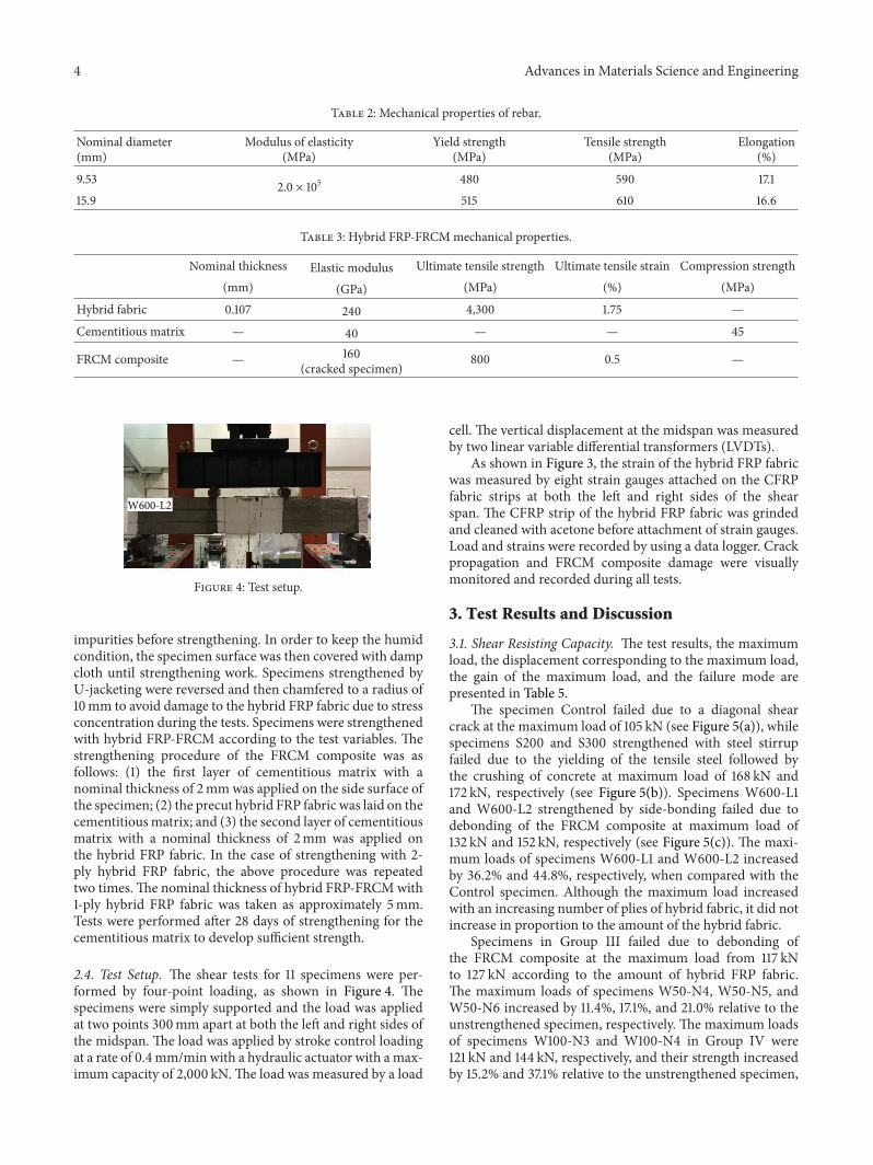
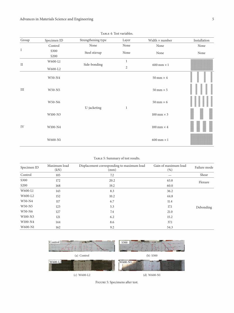
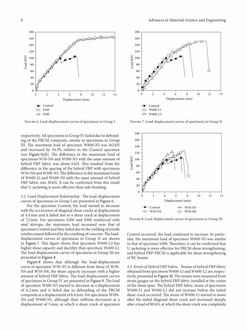
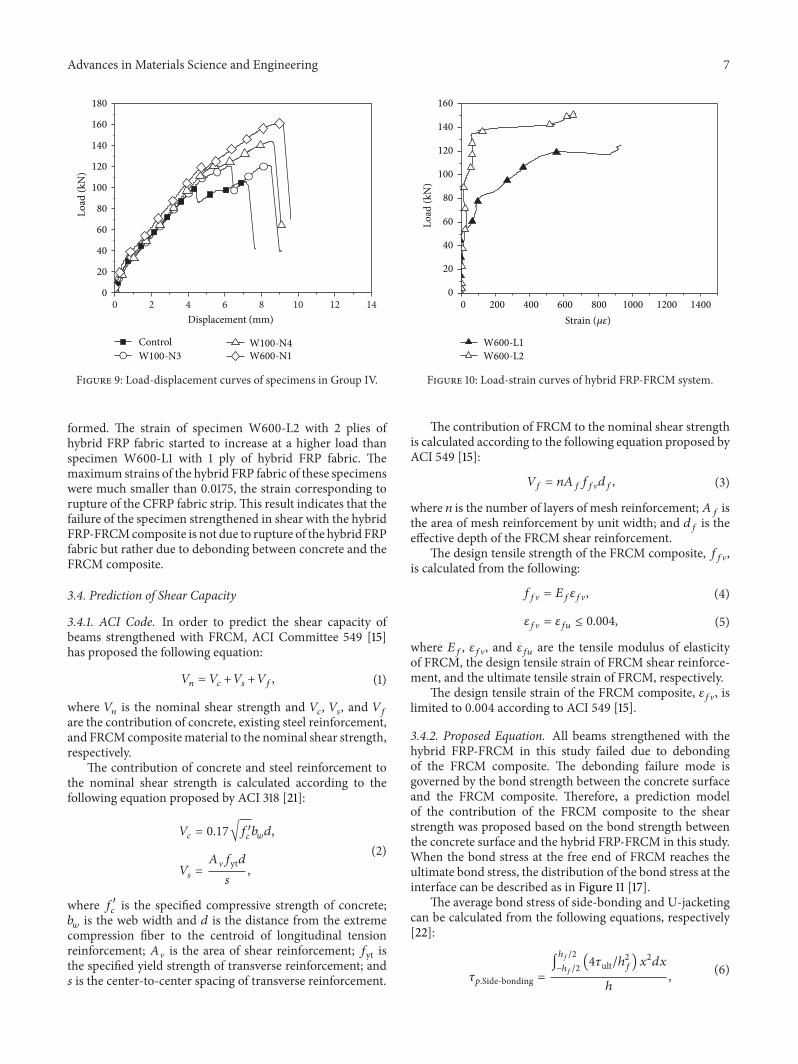
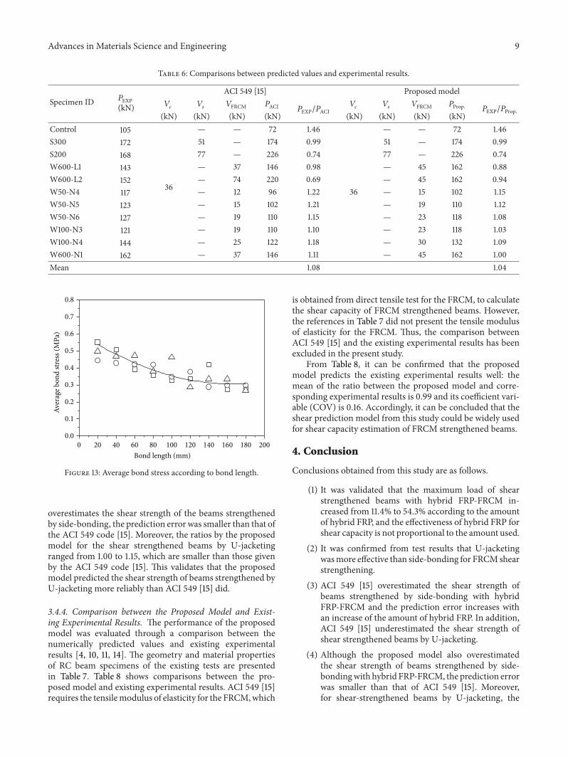
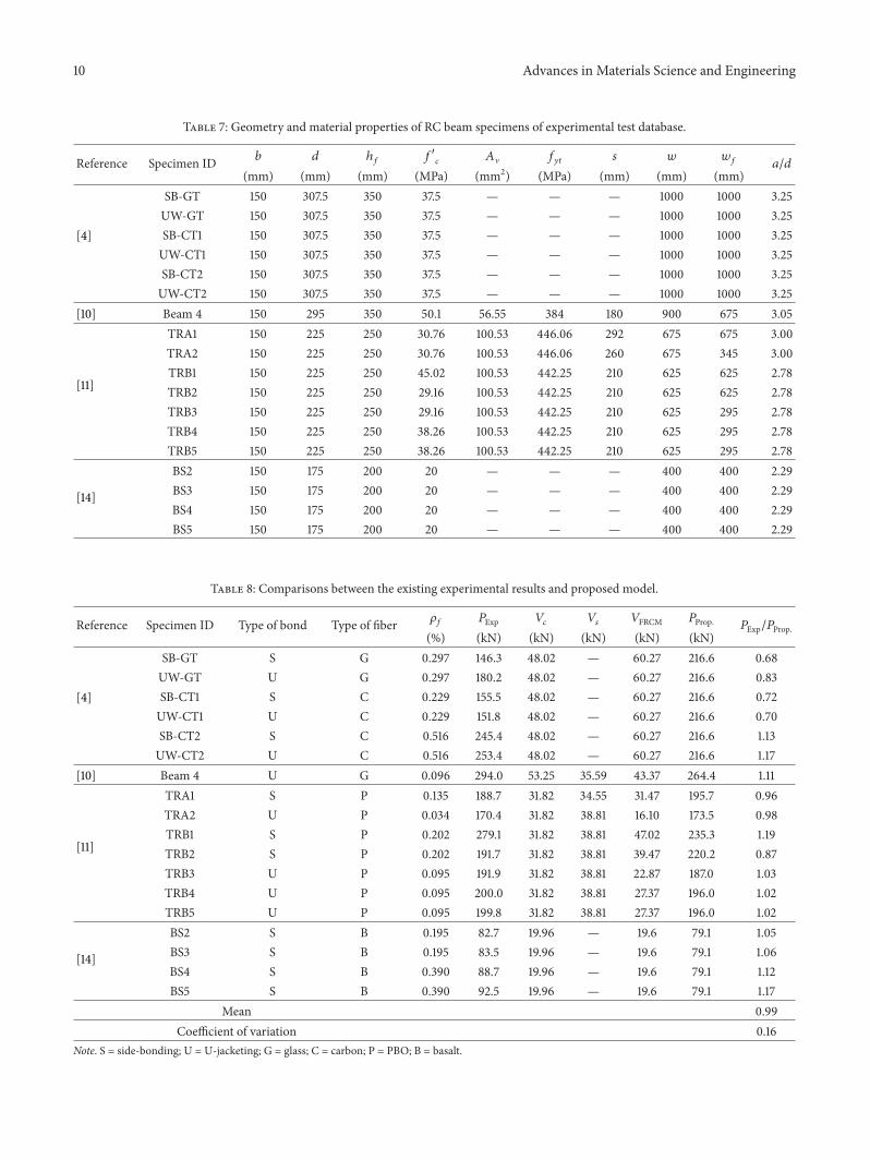