Embed Size (px)
Citation preview
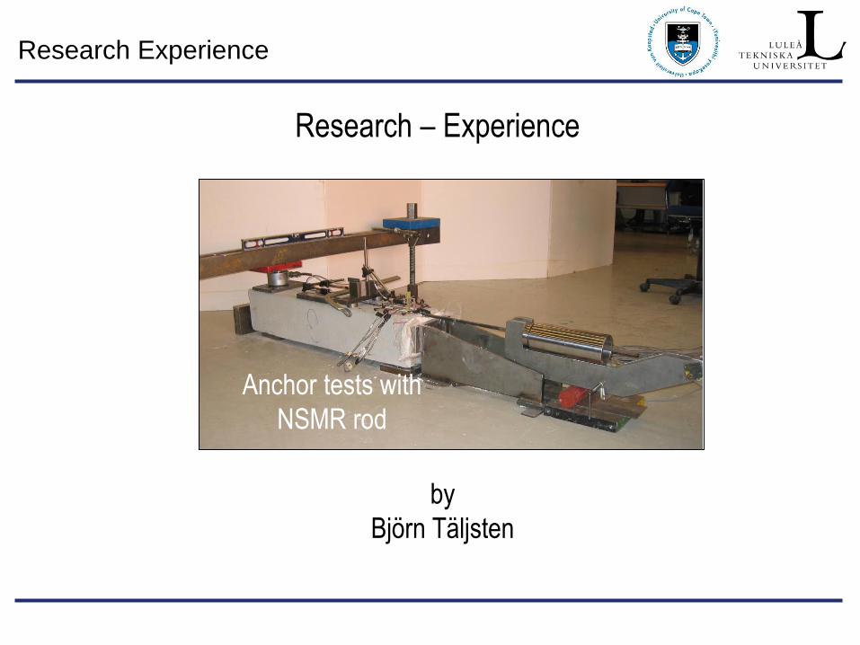
Research Experience
Research – Experience
by
Björn Täljsten
Anchor tests with
NSMR rod
Research Experience
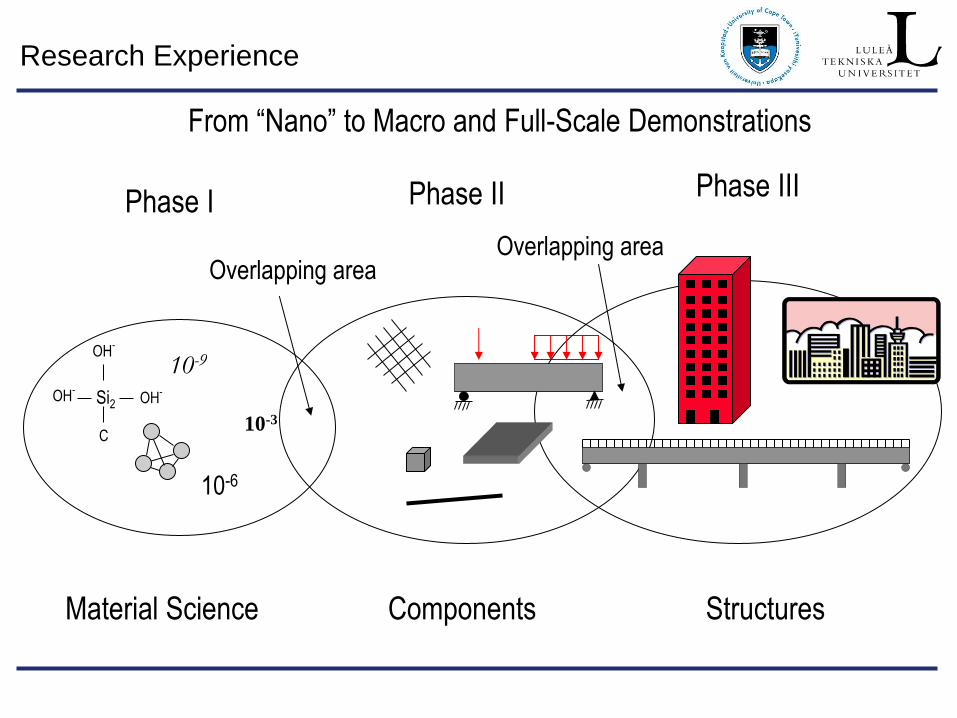
Material Science Components Structures
10-6
10-9
Si2 OH-
OH-
OH-
C 10-3
Overlapping area Overlapping area
Phase I Phase II Phase III
From “Nano” to Macro and Full-Scale Demonstrations
Research Experience
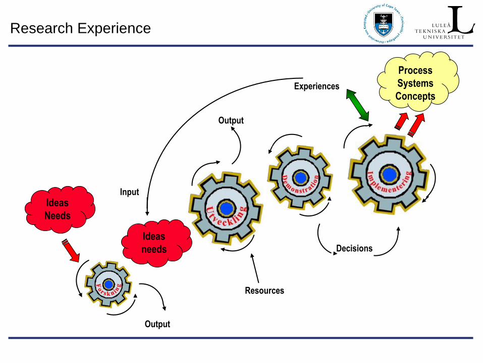
Ideas
needs
Process
Systems
Concepts
Decisions
Resources
Output
Output
Experiences
Ideas
Needs
Input
Research Experience
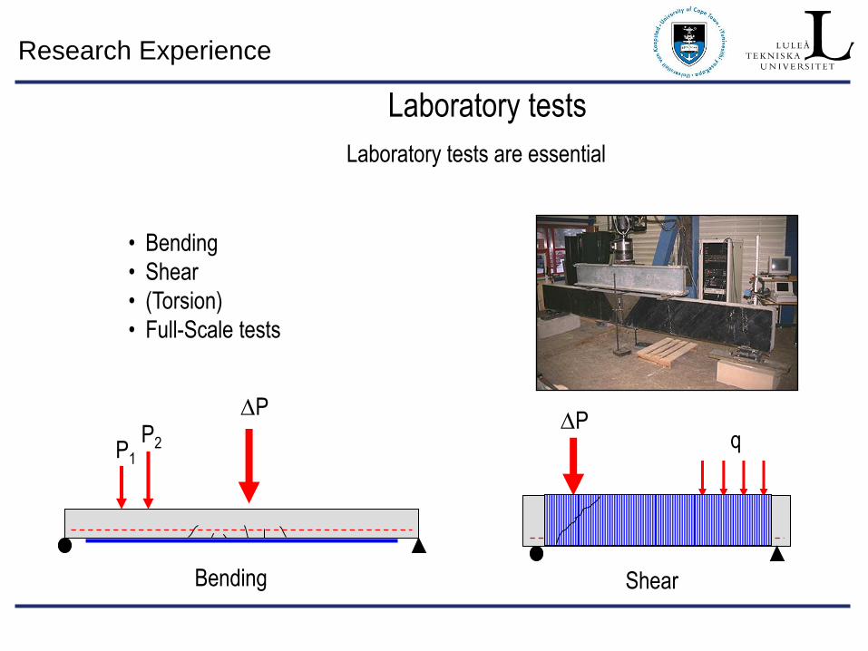
Laboratory tests
• Bending
• Shear
• (Torsion)
• Full-Scale tests
DP
P1 P2
Bending
q DP
Shear
Laboratory tests are essential
Research Experience
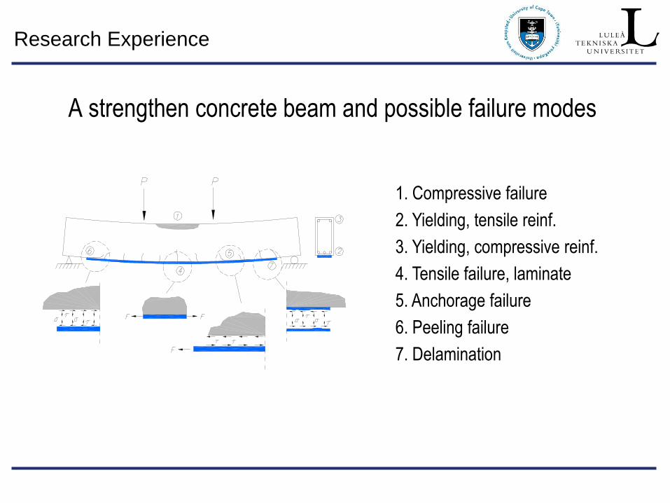
A strengthen concrete beam and possible failure modes
1. Compressive failure
2. Yielding, tensile reinf.
3. Yielding, compressive reinf.
4. Tensile failure, laminate
5. Anchorage failure
6. Peeling failure
7. Delamination
Research Experience
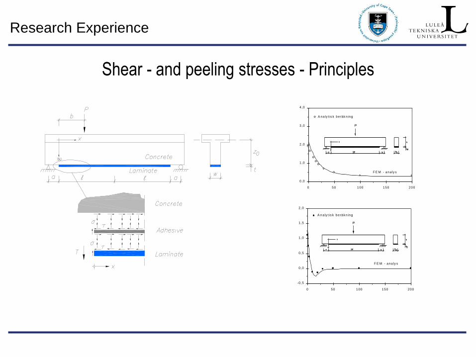
Shear - and peeling stresses - Principles
0 ,0
1 ,0
2 ,0
3 ,0
4 ,0
0 5 0 1 0 0 1 5 0 2 0 0
F E M - a n a ly s
A n a ly t is k b e rä k n in g
-0 ,5
0 ,0
0 ,5
1 ,0
1 ,5
2 ,0
0 50 100 150 200
F E M - ana ly s
A na ly t is k be räk n ing
Research Experience
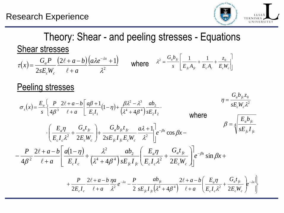
Theory: Shear - and peeling stresses - Equations
2
12
2
x
cc
a ea
a
ba
WsE
PGx
22
2
44
32
11
3 41
12
4 IsE
ab
IE
a
a
baP
s
Ex a
z
xe
a
WEIsE
tbG
WE
tG
IE
E x
ccfcfc
fcfca
cc
fca
cc
a
cos1
22 22
xe
WE
tG
IE
E
IsE
ab
IE
a
a
baP x
cc
fca
cc
a
fcfccc
sin24
12
4 2
2
44
2
2
x
cc
fca
cc
a
fcfc
fcx
cc
eWE
tG
IE
E
a
ba
IsE
abPe
a
a
ba
IE
P
2
2
42
2
2 2442
where
where
ccccfcfc
fca
WE
z
AEAEs
bG02 11
2
0
cc
fca
WsE
zbG
4
fcfc
fca
IsE
bE
Peeling stresses
Shear stresses
Research Experience
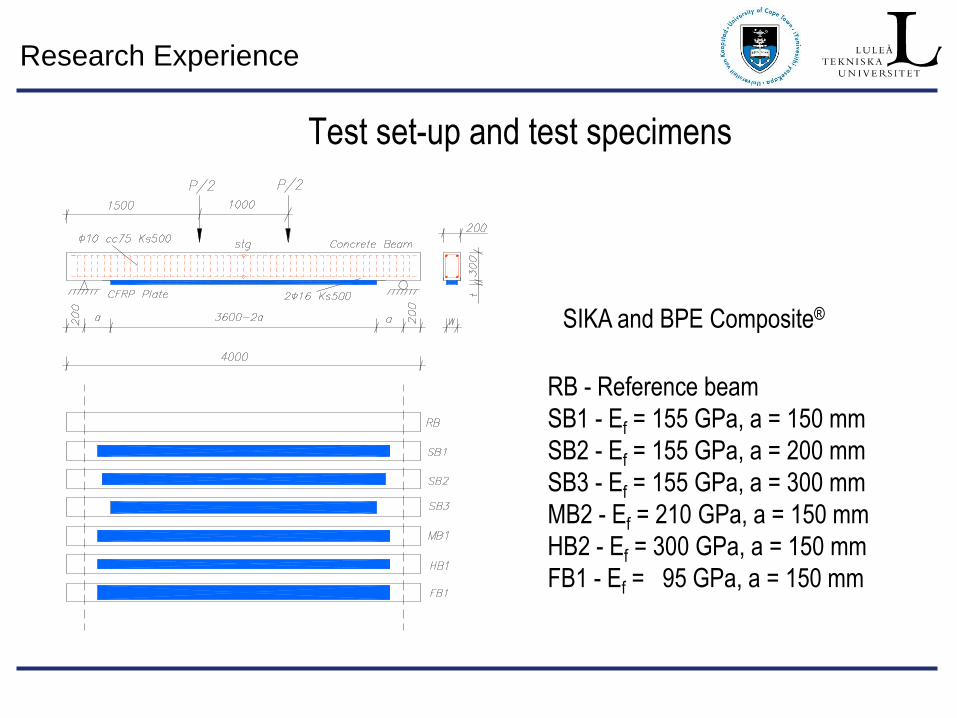
Test set-up and test specimens
RB - Reference beam
SB1 - Ef = 155 GPa, a = 150 mm
SB2 - Ef = 155 GPa, a = 200 mm
SB3 - Ef = 155 GPa, a = 300 mm
MB2 - Ef = 210 GPa, a = 150 mm
HB2 - Ef = 300 GPa, a = 150 mm
FB1 - Ef = 95 GPa, a = 150 mm
SIKA and BPE Composite®
Research Experience
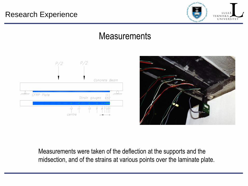
Measurements
Measurements were taken of the deflection at the supports and the
midsection, and of the strains at various points over the laminate plate.
Research Experience
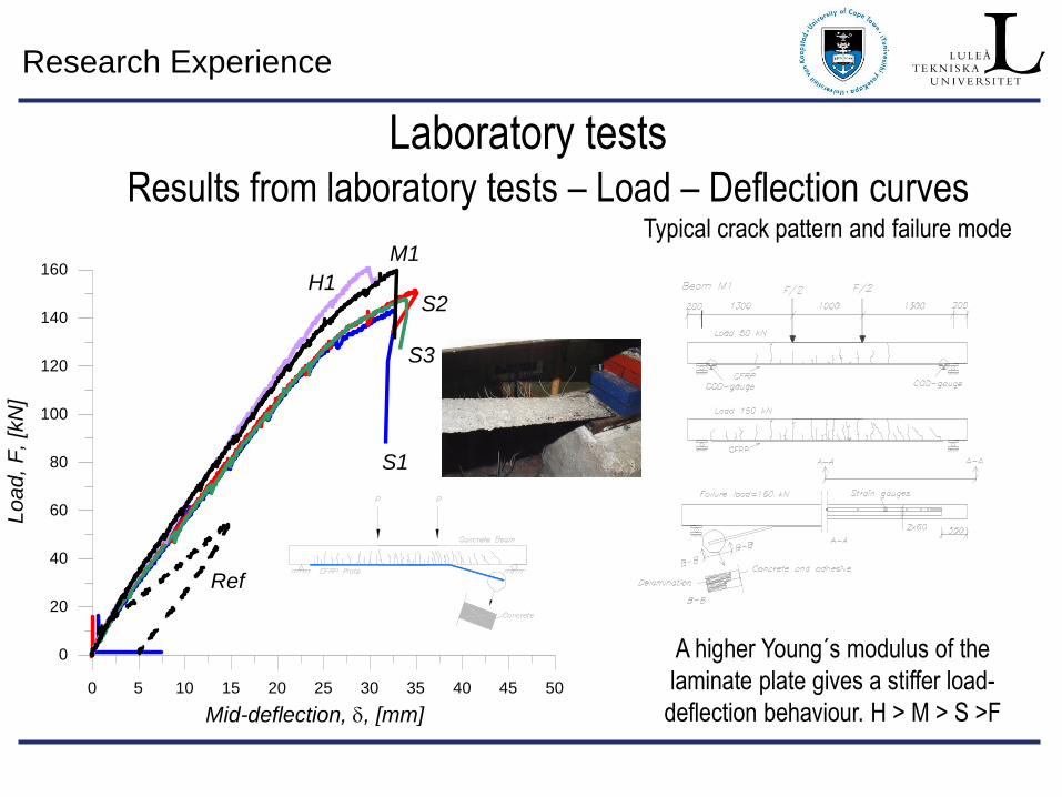
Laboratory tests Results from laboratory tests – Load – Deflection curves
Typical crack pattern and failure mode
0 5 10 15 20 25 30 35 40 45 50
Mid-deflection, , [mm]
0
20
40
60
80
100
120
140
160
Lo
ad,
F,
[kN
]
H1
Ref
S1
S2
S3
M1
A higher Young´s modulus of the
laminate plate gives a stiffer load-
deflection behaviour. H > M > S >F
Research Experience
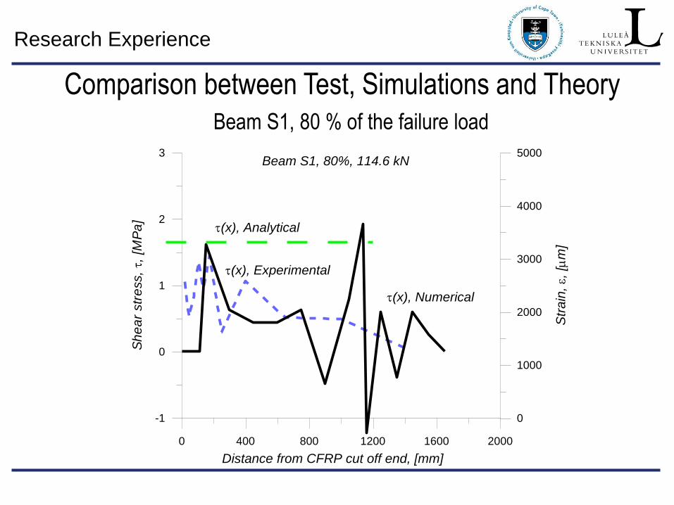
Comparison between Test, Simulations and Theory Beam S1, 80 % of the failure load
0 400 800 1200 1600 2000
Distance from CFRP cut off end, [mm]
-1
0
1
2
3
Sh
ea
r str
ess,,
[M
Pa
]
0
1000
2000
3000
4000
5000
Str
ain
, ,
[
m]
(x), Experimental
(x), Analytical
Beam S1, 80%, 114.6 kN
(x), Numerical
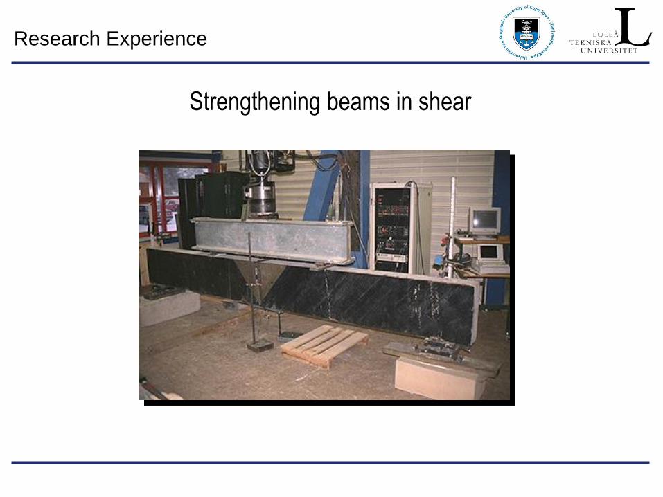
Research Experience
Strengthening beams in shear
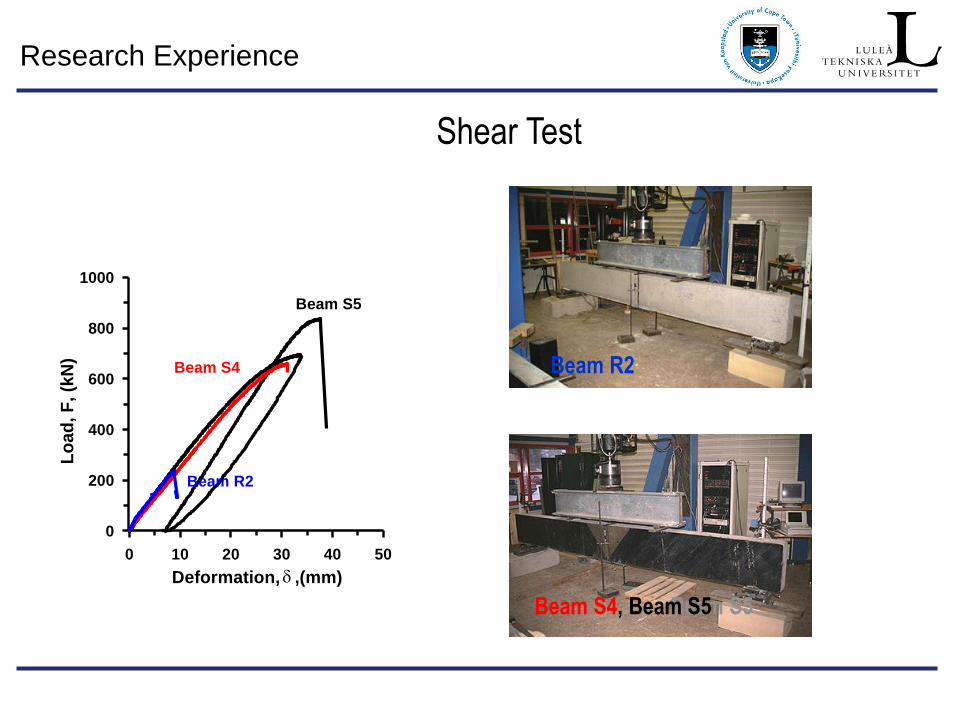
Research Experience
0 10 20 30 40 50
0
200
400
600
800
1000
Deformation, ,(mm)
Beam S5
Beam S4
Lo
ad
, F
, (k
N)
Beam R2
Beam R2
Beam S5 Beam S4, Beam S5
Shear Test
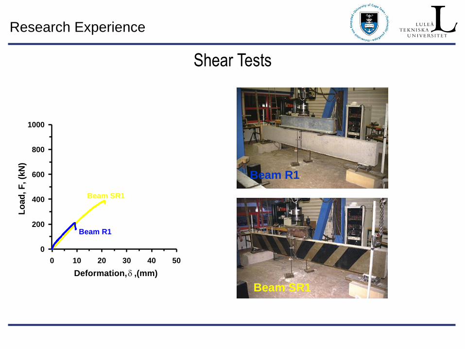
Research Experience
Beam R1
Beam SR1
0 10 20 30 40 50
Deformation, ,(mm)
Lo
ad
, F
, (k
N)
Beam R1
Beam SR1
0
200
400
600
800
1000
Shear Tests
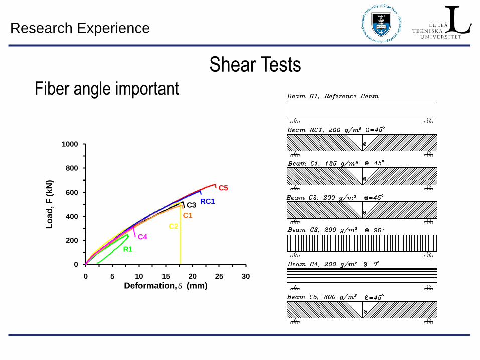
Research Experience
F
0
200
400
600
800
1000
Lo
ad
, (
kN
)
0 5 10 15 20 25 30
Deformation, (mm)
R1
C4
C2
C1
C3RC1
C5
Fiber angle important
Shear Tests
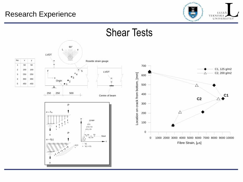
Research Experience
LVDT
Orgin
Rosette strain gauge
Centre of beam
LVDT
250 250 500
12
90°
No:
1
2
3
4
5
x
50
150
250
350
450
y
50
150
250
350
450
L T
5
4
3x
y
0 1000 2000 3000 4000 5000 6000 7000 8000 9000 10000
Fibre Strain, [s]
C1, 125 g/m2
C2, 200 g/m2
0
100
200
300
400
500
600
700
Loca
tio
n o
n c
rack f
rom
bo
tto
m,
[mm
]
C2C1
Shear Tests
P
P
y)
1
23
45
V
V
Steel
CFRP
1, 5
32, 4
S1, S5
C1, C5
C2, C4
C3
S2, S4
S3
x
x
x
x
x x x
V1
V2 > V1
1
2
34
5
fsy
f()
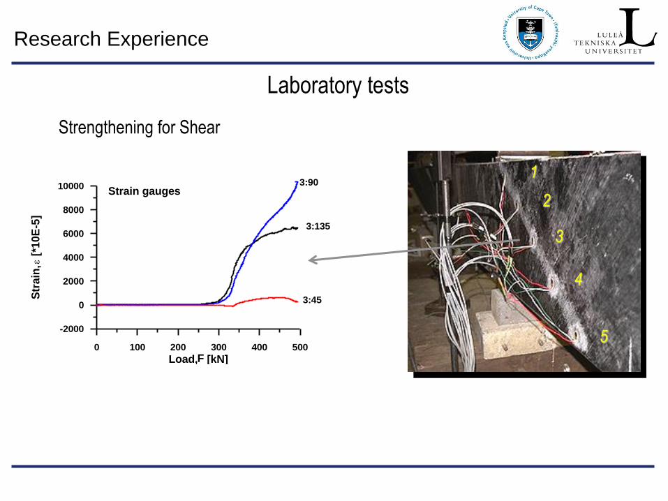
Research Experience
0 100 200 300 400 500
Load, [kN]
-2000
0
2000
4000
6000
8000
10000
Str
ain
, [*
10E
-5]
Strain gauges3:90
3:135
3:45
F
Strengthening for Shear
1
2
3
4
5
Laboratory tests
Research Experience
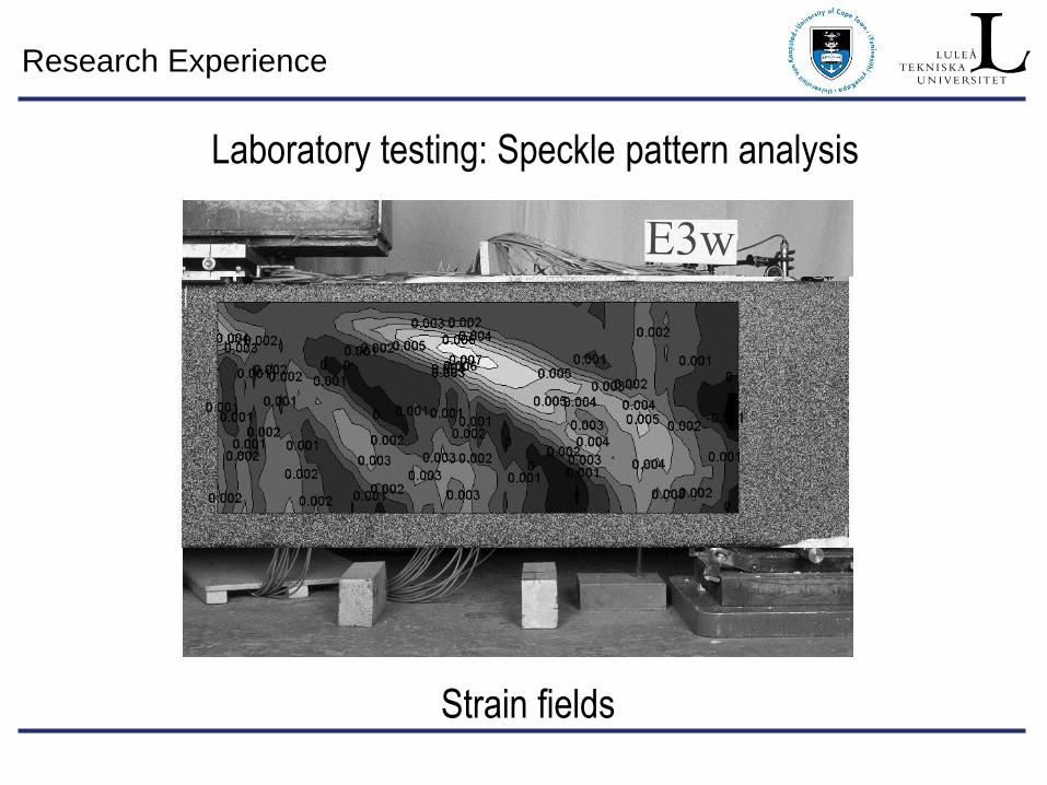
Strain fields
Laboratory testing: Speckle pattern analysis
Research Experience
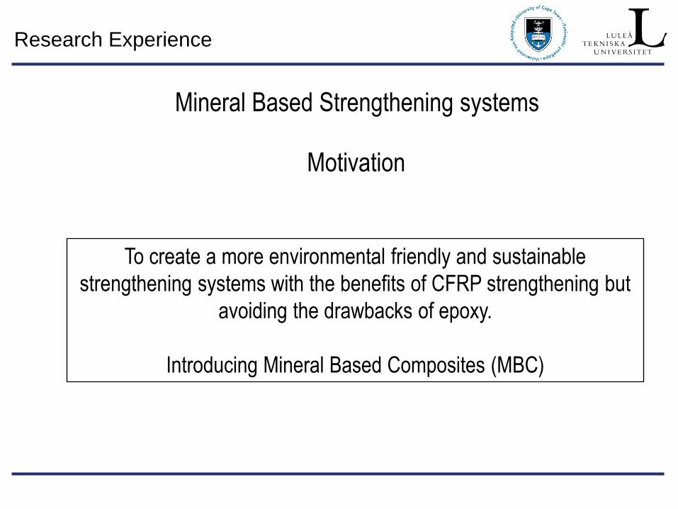
Mineral Based Strengthening systems
To create a more environmental friendly and sustainable
strengthening systems with the benefits of CFRP strengthening but
avoiding the drawbacks of epoxy.
Introducing Mineral Based Composites (MBC)
Motivation
Research Experience
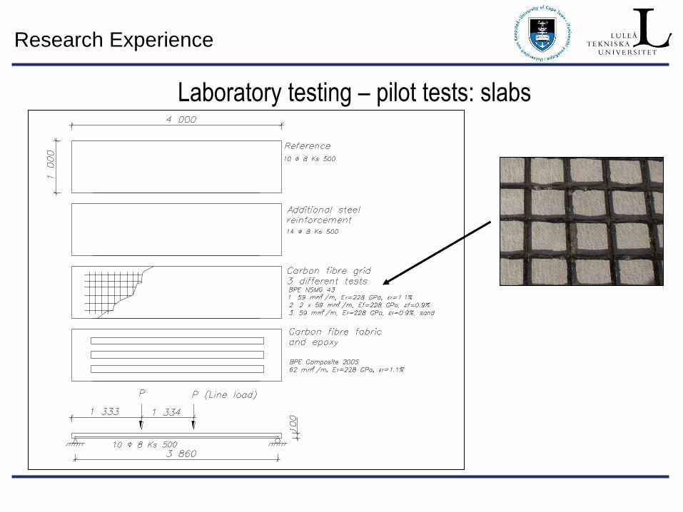
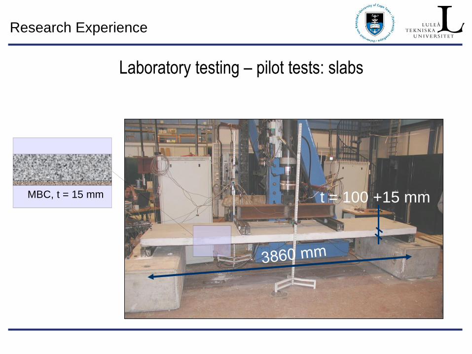
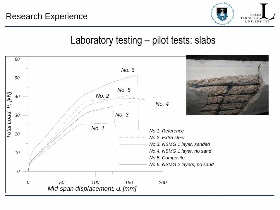
Laboratory testing – pilot tests: slabs
Research Experience
MBC, t = 15 mm t = 100 +15 mm
Laboratory testing – pilot tests: slabs
Research Experience
0 50 100 150 200
Mid-span displacement, d, [mm]
0
10
20
30
40
50
60
To
tal L
oa
d,
P,
[kN
]
No.1. Reference
No.2. Extra steel
No.3. NSMG 1 layer, sanded
No.4. NSMG 1 layer, no sand
No.5. Composite
No.6. NSMG 2 layers, no sand
No. 1
No. 2
No. 3
No. 4
No. 5
No. 6
Laboratory testing – pilot tests: slabs
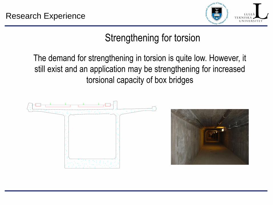
Research Experience
The demand for strengthening in torsion is quite low. However, it
still exist and an application may be strengthening for increased
torsional capacity of box bridges
Strengthening for torsion
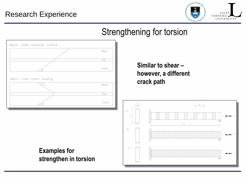
Research Experience
Similar to shear –
however, a different
crack path
Examples for
strengthen in torsion
Strengthening for torsion
Research Experience
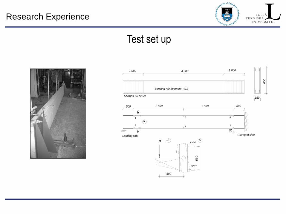
Test set up
Loading side Clamped side
LVDT
A
Stirrups 8 cc 50
600
Bending reinforcment 12
4 000
2 500500
150
60
0
50
35
1
LVDT
B A
53
0
P3
5
5002 500
2
3
4
5
6
1 000 1 000
Research Experience
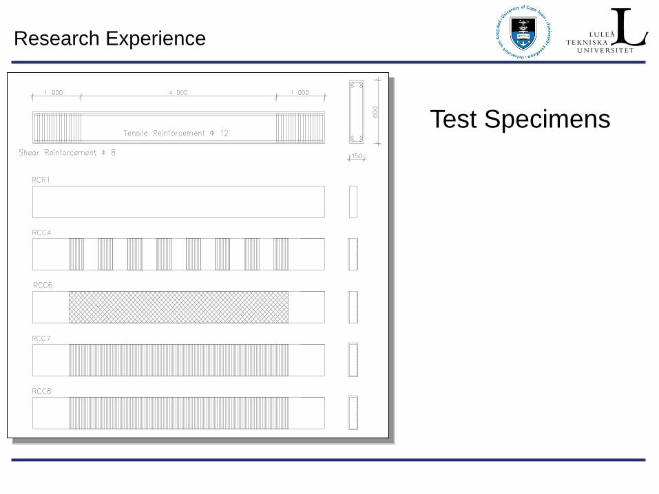
Test Specimens
Research Experience
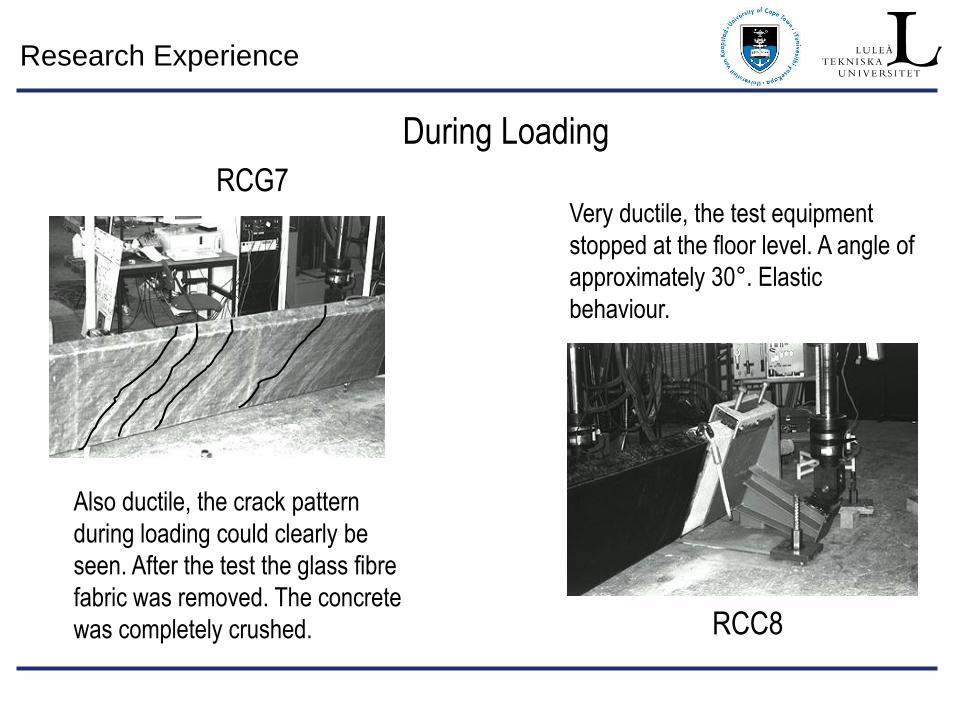
During Loading
Very ductile, the test equipment
stopped at the floor level. A angle of
approximately 30°. Elastic
behaviour.
RCG7
RCC8
Also ductile, the crack pattern
during loading could clearly be
seen. After the test the glass fibre
fabric was removed. The concrete
was completely crushed.
Research Experience
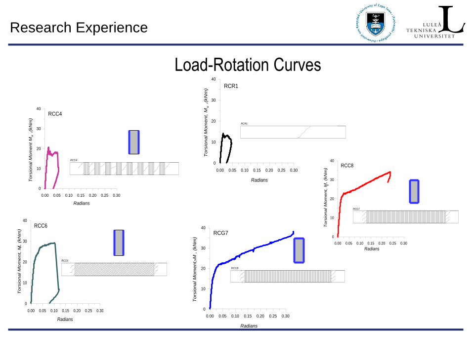
Load-Rotation Curves
RCC8
Radians
To
rsio
na
l M
om
en
t, M
, (
kN
m)
RCG7
v
0.00 0.05 0.10 0.15 0.20 0.25 0.30
0
10
20
30
40
RCG7
Radians
To
rsio
na
l M
om
en
t, M
, (k
Nm
)
RCC8
v
0.00 0.05 0.10 0.15 0.20 0.25 0.30
0
10
20
30
40
RCC6
Radians
To
rsio
na
l M
om
en
t, M
, (k
Nm
)
RCC6
v
0.00 0.05 0.10 0.15 0.20 0.25 0.30
0
10
20
30
40
RCC4
Radians
To
rsio
na
l M
om
en
t M
,
(kN
m)
RCC4
v
0.00 0.05 0.10 0.15 0.20 0.25 0.30
0
10
20
30
40
RCR1
Radians
To
rsio
na
l M
om
en
t, M
,
(kN
m) RCR1
v
0.00 0.05 0.10 0.15 0.20 0.25 0.30
0
10
20
30
40
Research Experience
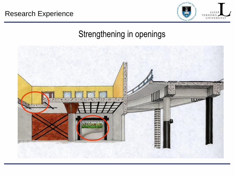
Strengthening in openings
Research Experience
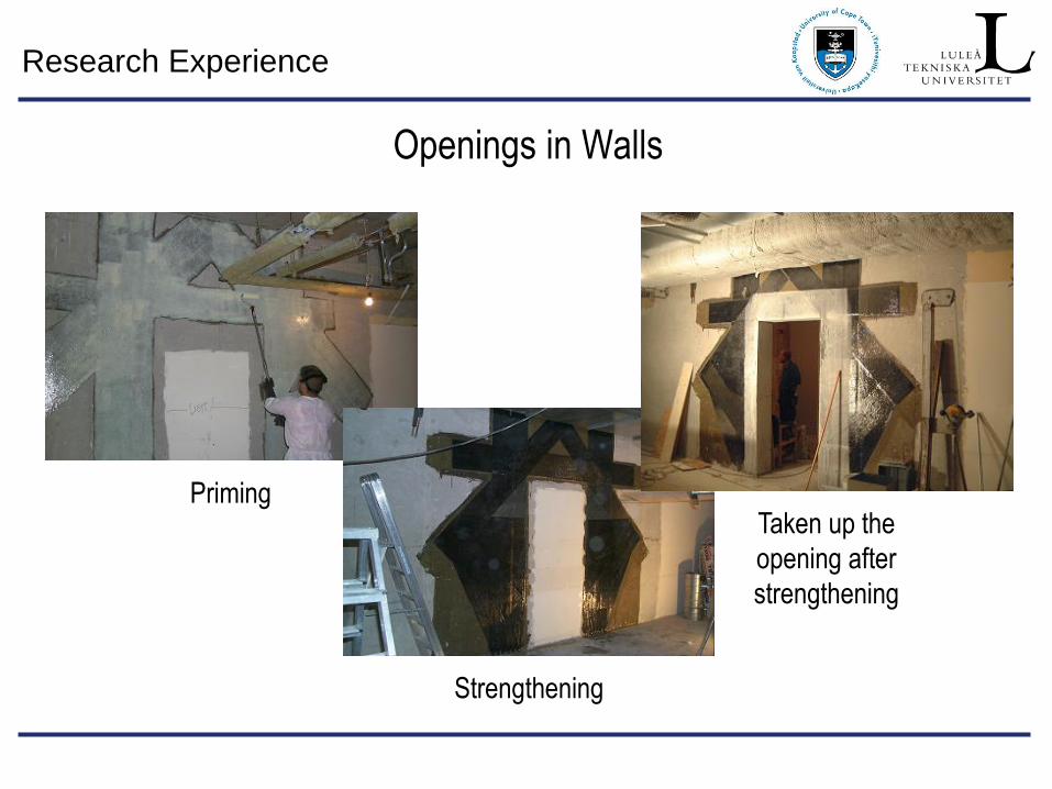
Openings in Walls
Priming
Strengthening
Taken up the
opening after
strengthening
Research Experience
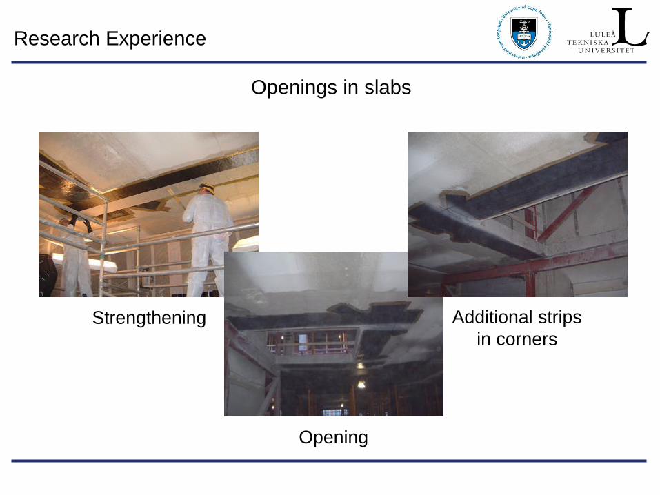
Strengthening
Opening
Additional strips
in corners
Openings in slabs
Research Experience
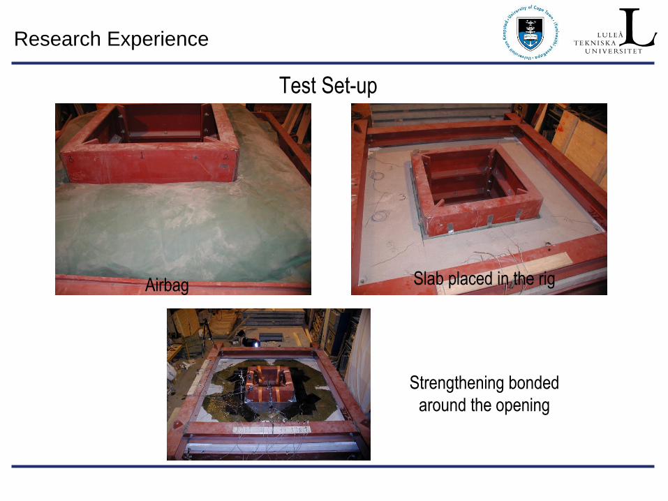
Test Set-up
Airbag Slab placed in the rig
Strengthening bonded
around the opening
Research Experience
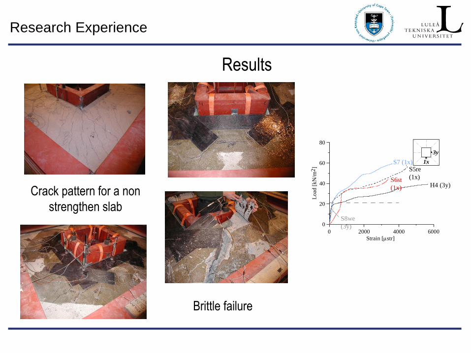
Results
Crack pattern for a non
strengthen slab
Brittle failure
0 2000 4000 6000
Strain [str]
0
20
40
60
80
Lo
ad [
kN
/m2
]
H4 (3y)
S5re
(1x)
S7 (1x)
S6st
(1x)
S8we
(3y)
1x
3y
Research Experience
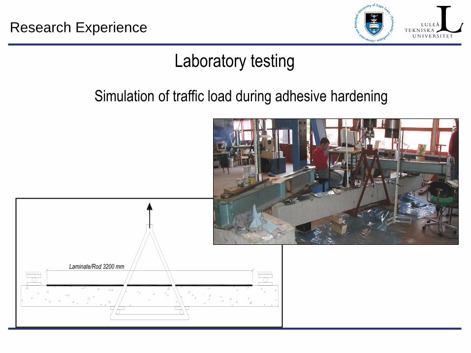
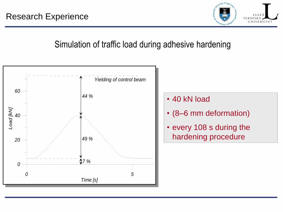
Simulation of traffic load during adhesive hardening
Laminate/Rod 3200 mm
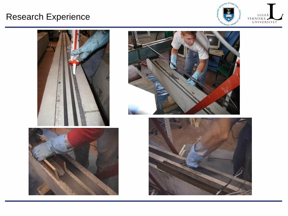
Laboratory testing
Research Experience
Research Experience
0 5Time [s]
0
20
40
60
Lo
ad
[kN
]
Yielding of control beam
44 %
49 %
7 %
• 40 kN load
• (8–6 mm deformation)
• every 108 s during the
hardening procedure
Simulation of traffic load during adhesive hardening
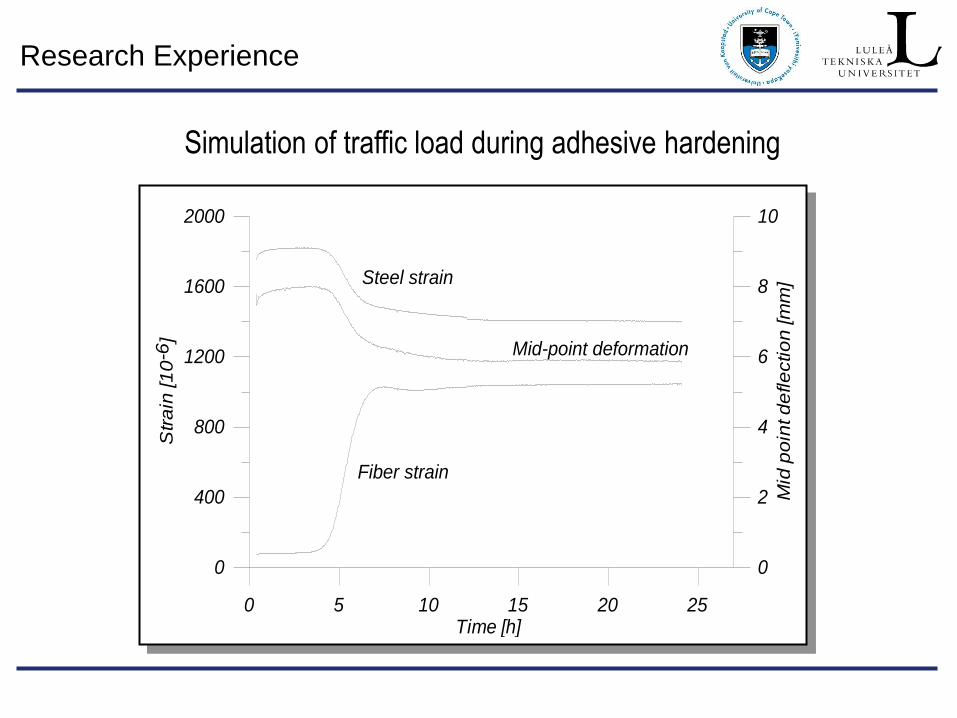
Research Experience
0 5 10 15 20 25Time [h]
0
400
800
1200
1600
2000
Str
ain
[1
0-6
]
0
2
4
6
8
10
Mid
po
int d
efle
ctio
n [m
m]Steel strain
Fiber strain
Mid-point deformation
Simulation of traffic load during adhesive hardening
Research Experience
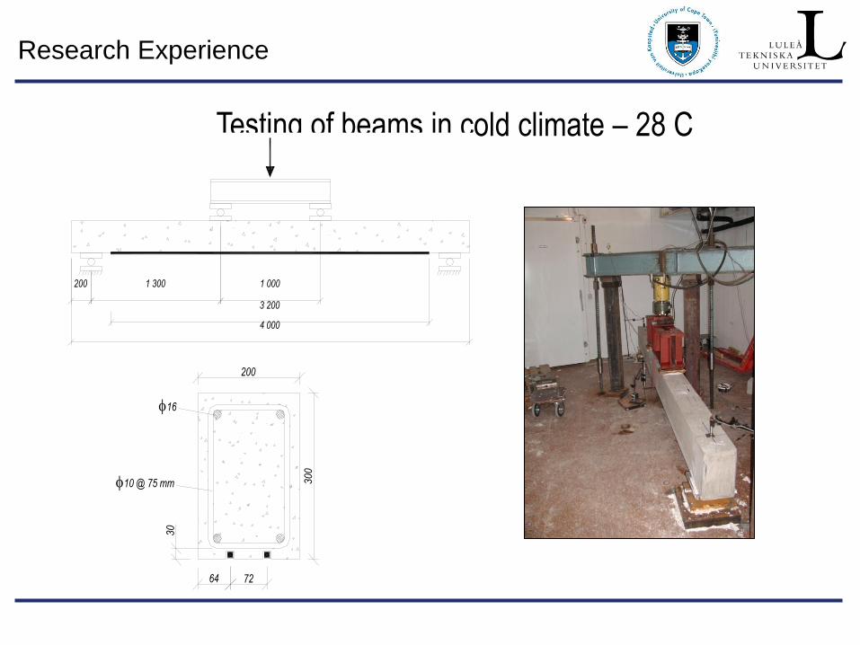
Testing of beams in cold climate – 28 C
4 000
3 200
1 300200 1 000
200
30
0
64 72
30
16
10 @ 75 mm
Research Experience
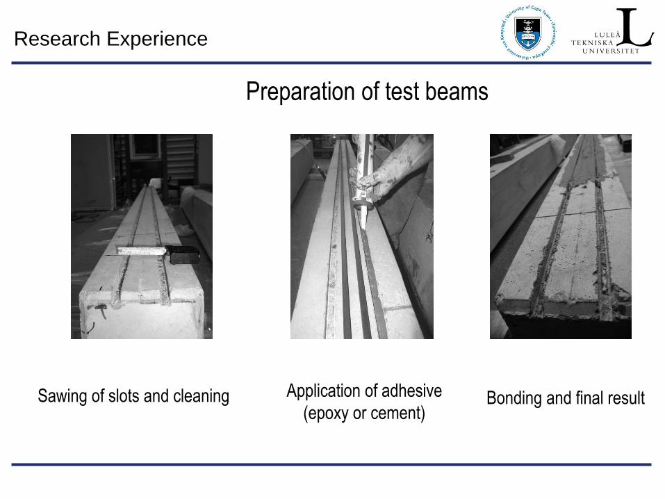
Preparation of test beams
Sawing of slots and cleaning Application of adhesive
(epoxy or cement) Bonding and final result
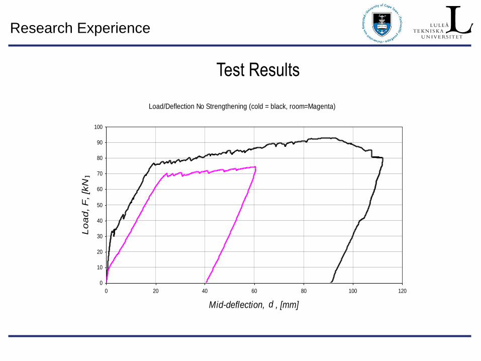
Research Experience
Test Results
Load/Deflection No Strengthening (cold = black, room=Magenta)
0
10
20
30
40
50
60
70
80
90
100
0 20 40 60 80 100 120
Mid-deflection, d , [mm]
Lo
ad
, F
, [k
N]
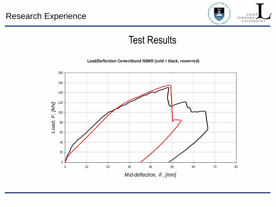
Research Experience
Test Results
Load/Deflection Cementbond NSMR (cold = black, room=red)
0
20
40
60
80
100
120
140
160
180
0 10 20 30 40 50 60 70 80
Mid-deflection, d , [mm]
Load, F
, [k
N]
Research Experience
Test Results
0
20
40
60
80
100
120
140
160
180
0 10 20 30 40 50 60 70 80
Mid-deflection, d , [mm] ]
Lo
ad
, F
, [k
N]
Load/Deflection Epoxy Bond NSMR (cold = black, room=blue)
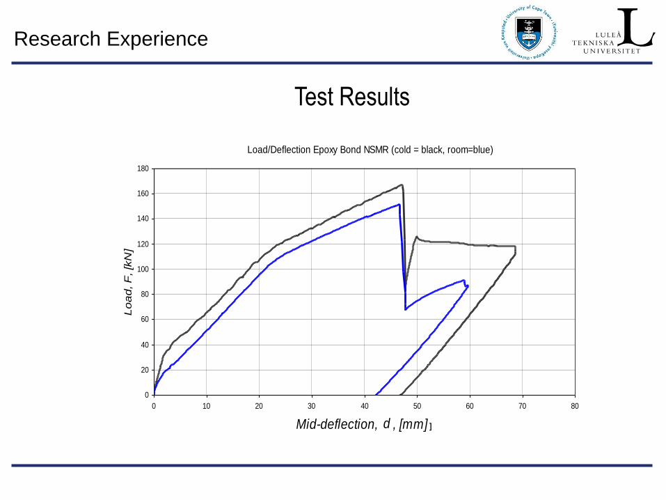
Research Experience
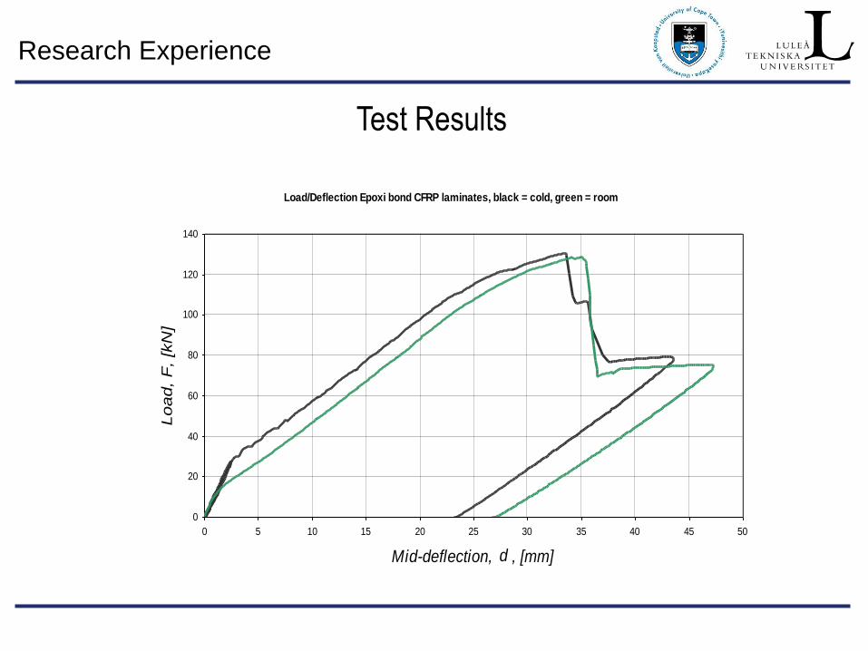
Test Results
Load/Deflection Epoxi bond CFRP laminates, black = cold, green = room
0
20
40
60
80
100
120
140
0 5 10 15 20 25 30 35 40 45 50
Mid-deflection, d , [mm]
Load, F
, [k
N]
Research Experience
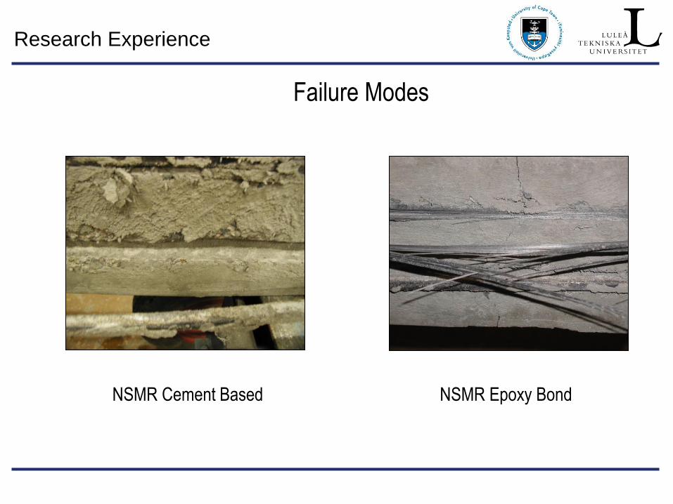
Failure Modes
NSMR Cement Based NSMR Epoxy Bond
Research Experience
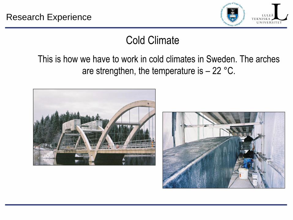
Cold Climate
This is how we have to work in cold climates in Sweden. The arches
are strengthen, the temperature is – 22 °C.
Research Experience
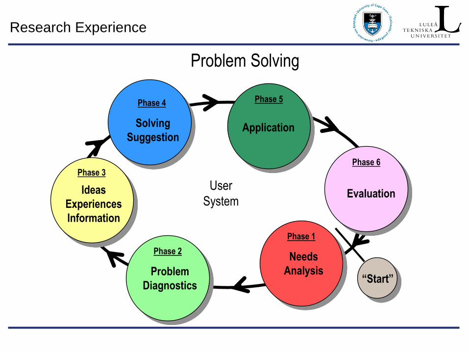
Problem Solving
Problem
Diagnostics
Phase 2 Needs
Analysis
Phase 1
Ideas
Experiences
Information
Phase 3
Solving
Suggestion
Phase 4
Application
Phase 5
User
System Evaluation
Phase 6
“Start”
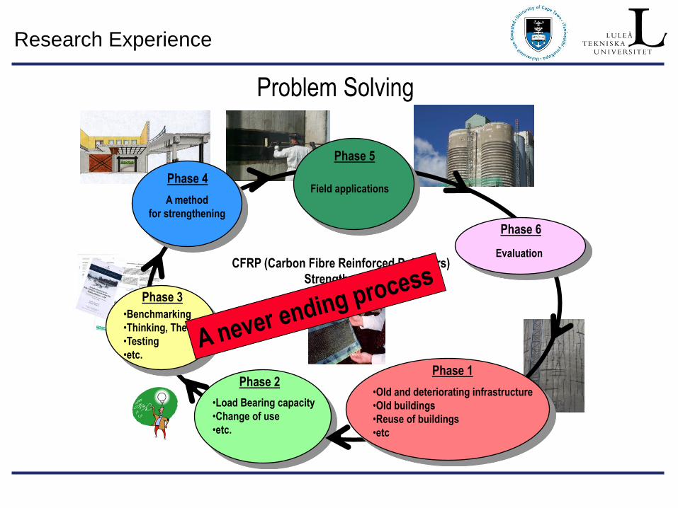
Research Experience
•Load Bearing capacity
•Change of use
•etc.
Phase 2 •Old and deteriorating infrastructure
•Old buildings
•Reuse of buildings
•etc
Phase 1
•Benchmarking
•Thinking, Theory
•Testing
•etc.
Phase 3
A method
for strengthening
Phase 4 Field applications
Phase 5
CFRP (Carbon Fibre Reinforced Polymers)
Strengthening
Evaluation
Phase 6
Problem Solving
Research Experience
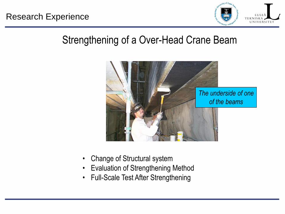
Strengthening of a Over-Head Crane Beam
• Change of Structural system
• Evaluation of Strengthening Method
• Full-Scale Test After Strengthening
The underside of one
of the beams
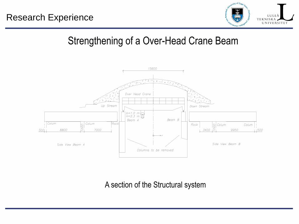
Research Experience
A section of the Structural system
Strengthening of a Over-Head Crane Beam
Research Experience
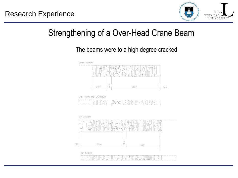
The beams were to a high degree cracked
Strengthening of a Over-Head Crane Beam
Research Experience
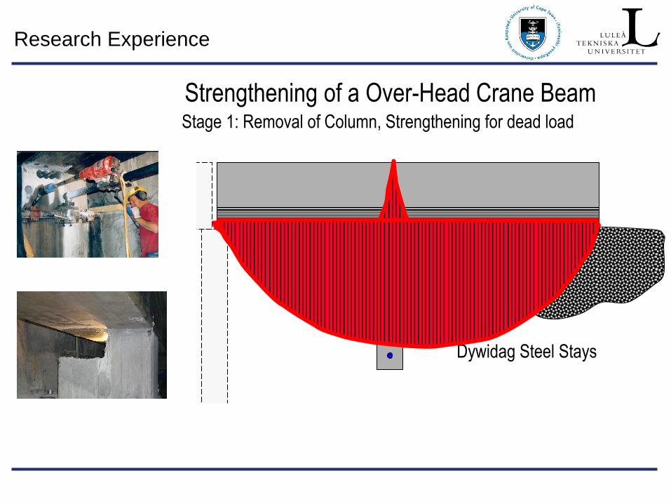
Stage 1: Removal of Column, Strengthening for dead load
Dywidag Steel Stays
Strengthening of a Over-Head Crane Beam
Research Experience
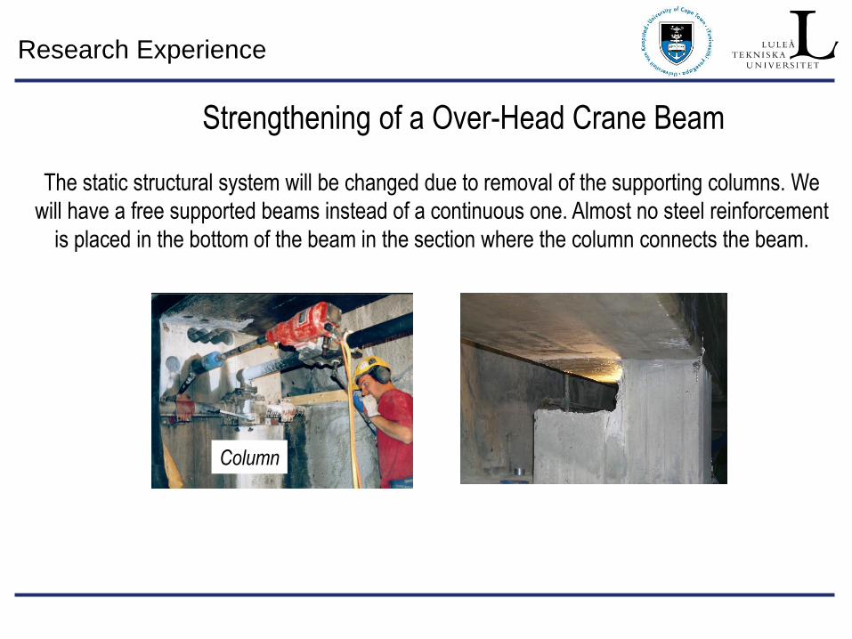
The static structural system will be changed due to removal of the supporting columns. We
will have a free supported beams instead of a continuous one. Almost no steel reinforcement
is placed in the bottom of the beam in the section where the column connects the beam.
Column
Strengthening of a Over-Head Crane Beam
Research Experience
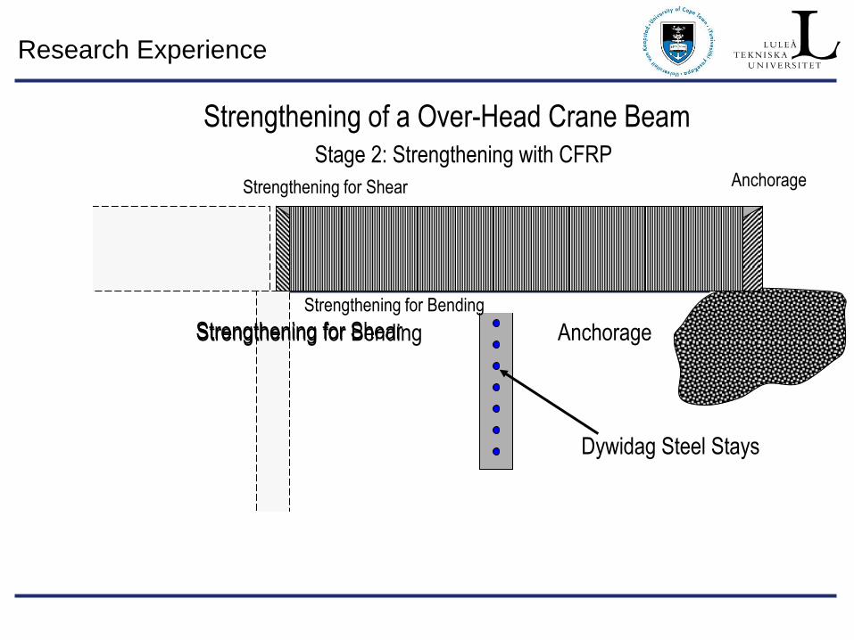
Stage 2: Strengthening with CFRP
Dywidag Steel Stays
Strengthening for Bending Anchorage Strengthening for Shear
Strengthening for Shear
Strengthening for Bending
Anchorage
Strengthening of a Over-Head Crane Beam
Research Experience
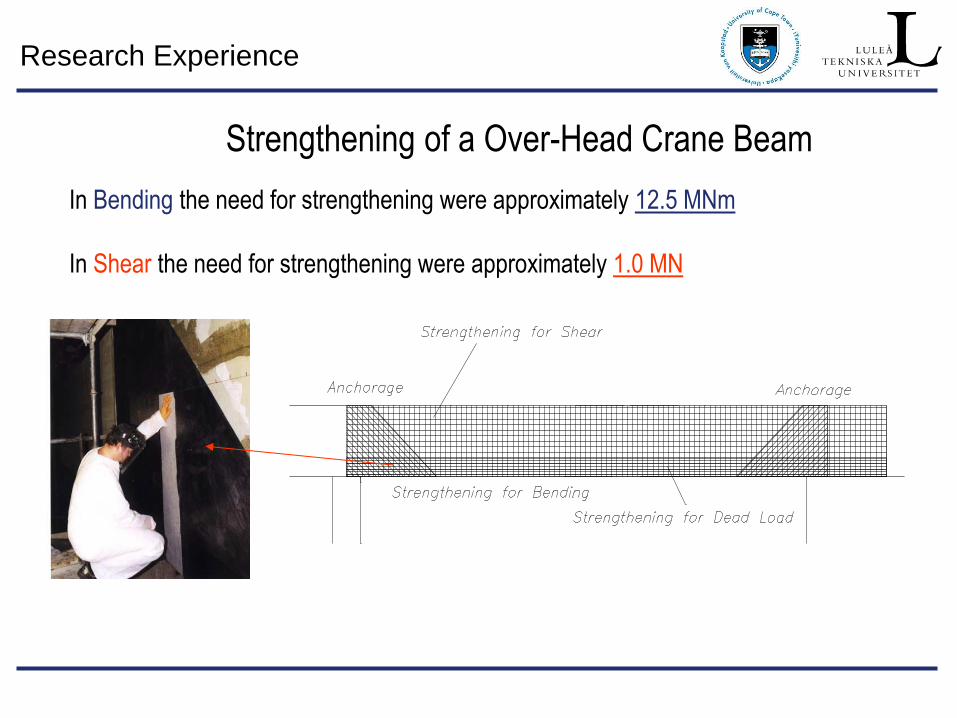
In Bending the need for strengthening were approximately 12.5 MNm
In Shear the need for strengthening were approximately 1.0 MN
Strengthening of a Over-Head Crane Beam
Research Experience
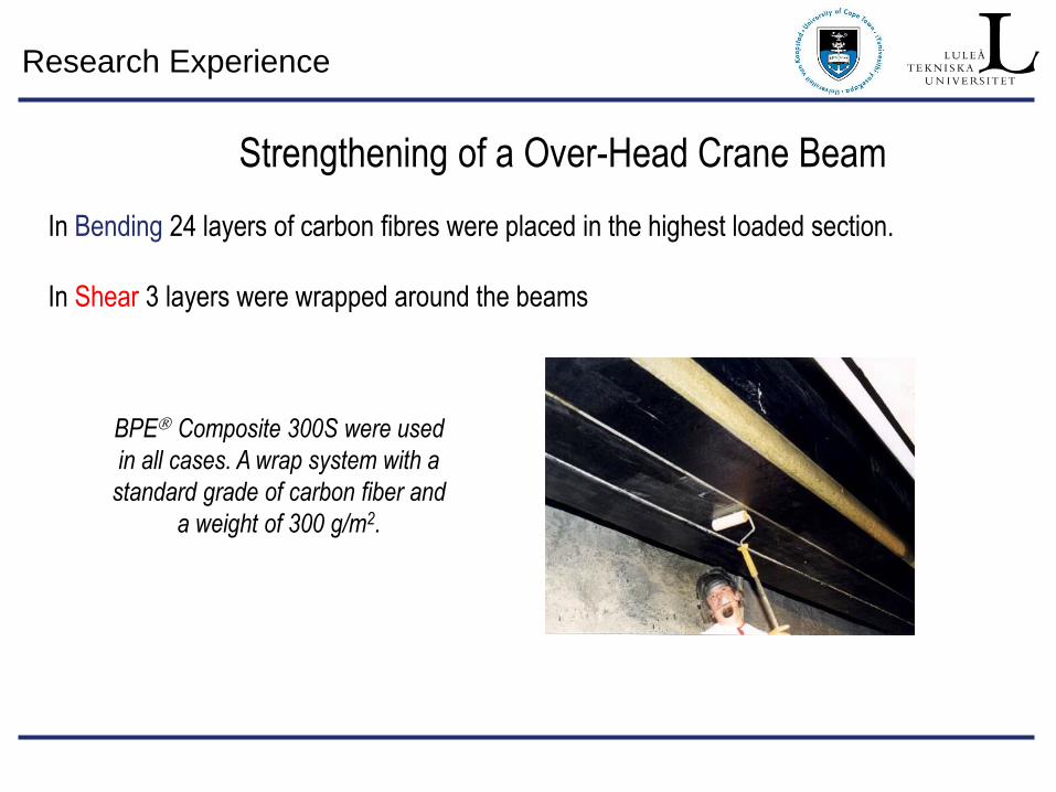
In Bending 24 layers of carbon fibres were placed in the highest loaded section.
In Shear 3 layers were wrapped around the beams
BPE Composite 300S were used
in all cases. A wrap system with a
standard grade of carbon fiber and
a weight of 300 g/m2.
Strengthening of a Over-Head Crane Beam
Research Experience
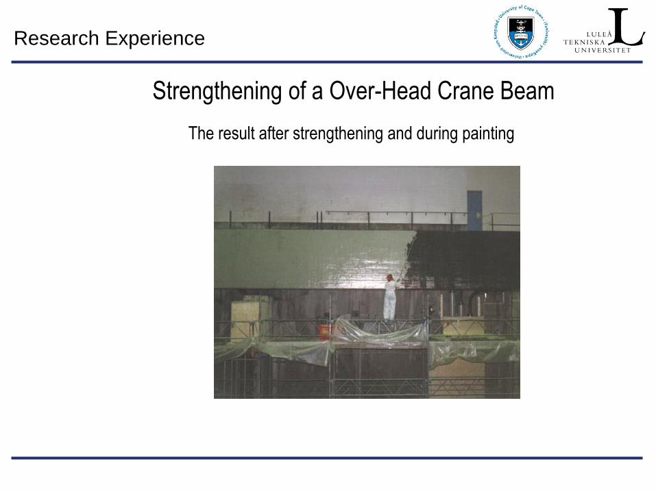
The result after strengthening and during painting
Strengthening of a Over-Head Crane Beam
Research Experience
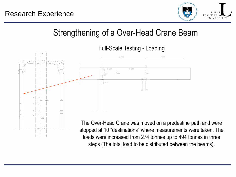
Full-Scale Testing - Loading
The Over-Head Crane was moved on a predestine path and were
stopped at 10 “destinations” where measurements were taken. The
loads were increased from 274 tonnes up to 494 tonnes in three
steps (The total load to be distributed between the beams).
Strengthening of a Over-Head Crane Beam
Research Experience
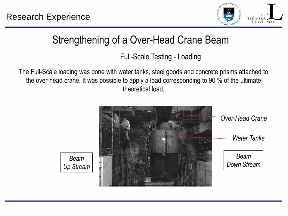
Full-Scale Testing - Loading
The Full-Scale loading was done with water tanks, steel goods and concrete prisms attached to
the over-head crane. It was possible to apply a load corresponding to 90 % of the ultimate
theoretical load.
Water Tanks
Beam
Up Stream
Beam
Down Stream
Over-Head Crane
Strengthening of a Over-Head Crane Beam
Research Experience
Full-Scale Testing - Testing Path
Strain Gauge T5
0 1000 2000 3000
Time, [sek]
0
100
200
300
400
500
Str
ain
, [m
s]
3
2
1
4
6
78
9
6
78
9
Strengthening of a Over-Head Crane Beam
1
2
3
4 6
7
8 9
Research Experience
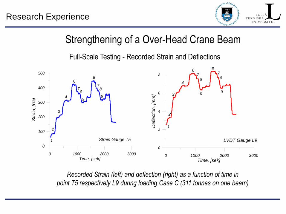
Full-Scale Testing - Recorded Strain and Deflections
Recorded Strain (left) and deflection (right) as a function of time in
point T5 respectively L9 during loading Case C (311 tonnes on one beam)
Strain Gauge T5
0 1000 2000 3000
Time, [sek]
0
100
200
300
400
500
Str
ain
, [m
s]
3
2
1
4
6
78
9
6
78
9
LVDT Gauge L9
0 1000 2000 3000
Time, [sek]
0
2
4
6
8
Defle
ctio
n,
[mm
]
1
2
3
4
67
8
9
67
8
9
Strengthening of a Over-Head Crane Beam
Research Experience
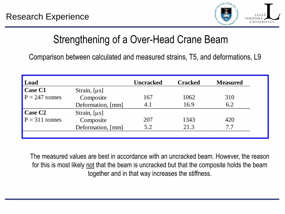
Comparison between calculated and measured strains, T5, and deformations, L9
Load Uncracked Cracked Measured
Case C1
P = 247 tonnesStrain, [s]
Composite
Deformation, [mm]
167
4.1
1062
16.9
310
6.2
Case C2
P = 311 tonnesStrain, [s]
Composite
Deformation, [mm]
207
5.2
1343
21.3
420
7.7
The measured values are best in accordance with an uncracked beam. However, the reason
for this is most likely not that the beam is uncracked but that the composite holds the beam
together and in that way increases the stiffness.
Strengthening of a Over-Head Crane Beam
Research Experience
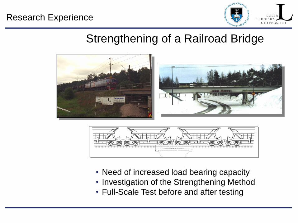
Strengthening of a Railroad Bridge
• Need of increased load bearing capacity
• Investigation of the Strengthening Method
• Full-Scale Test before and after testing
Research Experience
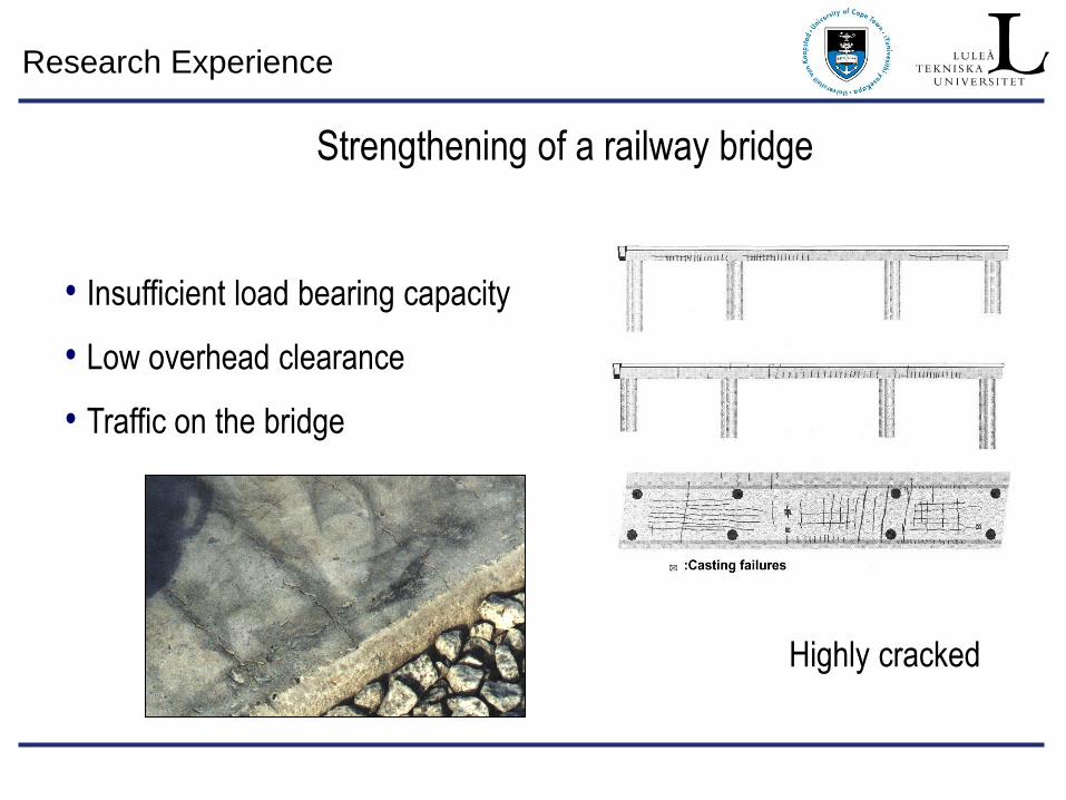
Strengthening of a railway bridge
Highly cracked
• Insufficient load bearing capacity
• Low overhead clearance
• Traffic on the bridge
Research Experience
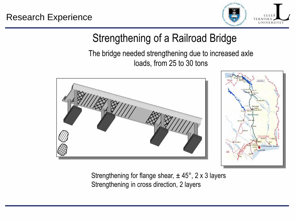
The bridge needed strengthening due to increased axle
loads, from 25 to 30 tons
Strengthening of a Railroad Bridge
Strengthening for flange shear, ± 45°, 2 x 3 layers
Strengthening in cross direction, 2 layers
Research Experience
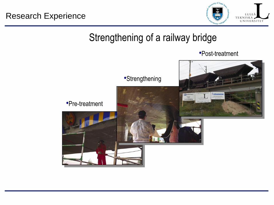
•Post-treatment
•Pre-treatment
•Strengthening
Strengthening of a railway bridge
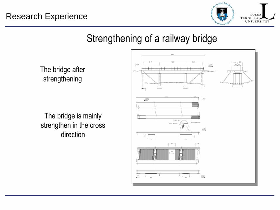
Research Experience
The bridge after
strengthening
The bridge is mainly
strengthen in the cross
direction
Strengthening of a railway bridge
Research Experience
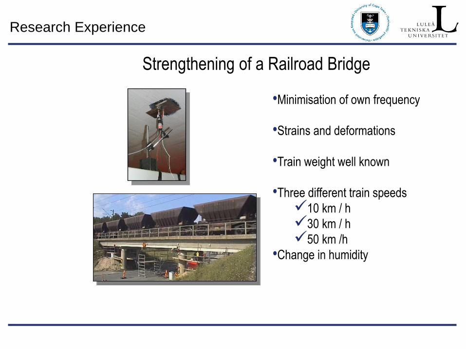
Strengthening of a Railroad Bridge
•Minimisation of own frequency
•Strains and deformations
•Train weight well known
•Three different train speeds
10 km / h
30 km / h
50 km /h
•Change in humidity
Research Experience
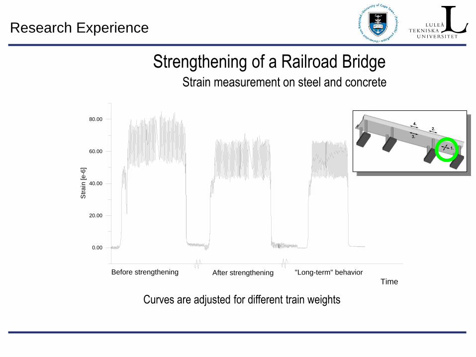
Strengthening of a Railroad Bridge
Curves are adjusted for different train weights
0.00
20.00
40.00
60.00
80.00
Str
ain
[e
-6]
Time
Before strengthening After strengthening "Long-term" behavior
Strain measurement on steel and concrete
Research Experience
Strengthening of a Railroad Bridge
0.00 0.50 1.00 1.50 2.00
-0.4
-0.3
-0.2
-0.1
0.0
De
fle
ctio
n,
[mm
]
Distance from support, [m]
Deflection in slab
Before strengthening
After strengthening
Measurement of deformations at two locations
Research Experience
Conclusions
• Advanced composite materials are very suitable for strengthen concrete structures.
• Full scale tests verify results from theory and laboratory tests
• Theory for design correspond well with actual test results
• Also very complicated structures and systems can be strengthened with CFRP
Strengthening of Concrete Structures