Embed Size (px)
Citation preview
f
SECURITY INFORMATION . - ~-CONfiDENTIAL Copy 318
RM L52J09
RESEARCH MEMORAN DUM
INVESTIGATION AT TRANSONIC SPEEDS OF THE EFFECT OF A
POSITIVE-LIFT BALANCING TAB ON THE HINGE-MOMENT
AND LIFT CHARACTERISTICS OF A FULL-SPAN
FLAP ON A TAPERED 450 SWEPTBACK
WING OF ASPECT RATIO 3
By Vernard E. Lockwood and Joseph E. Fikes
Langley Aeronautical Laboratory Lan~J3~ld v,a.. .
..... -::tH'1..m'l' ... UN Cffi.tmED TO UNGLM~cIFIED
:.U'!'HOR ITY J .\l" ChG':J!.CY DATE 1()"'29 .. 54
CI.JISSIFIED DOCUMENT
This material conta1ns information atfecUng the National Defense of the United States Within the meaning of the espionage laws, TiUe 18, U.S.C., Sees. 793 and 794, the transm1ss1on or revelation of which in any manner to unauthorized person is prohibited by law.
NATIONAL ADVISORY COMMITTEE FOR AERONAUTICS
WASHINGTON
November 20, 1952
----------~.----
s NACA RM L52J09 CONFIDENTIAL
NATIONAL ADVISORY COMMITTEE FOR AERONAUTICS
RESEARCH MEMORANDUM
INVESTIGATION AT TRANSONIC SPEEDS OF THE EFFECT OF A
POSITIVE-LIFT BALANCING TAB ON THE HINGE-MOMENT
AND LIFT CHARACTERISTICS OF A FULL-SPAN
FLAP ON A TAPERED 450 SWEPTBACK
WING OF ASPECT RATIO 3
By Vernard E. Lockwood and Joseph E. Fikes
SUMMARY
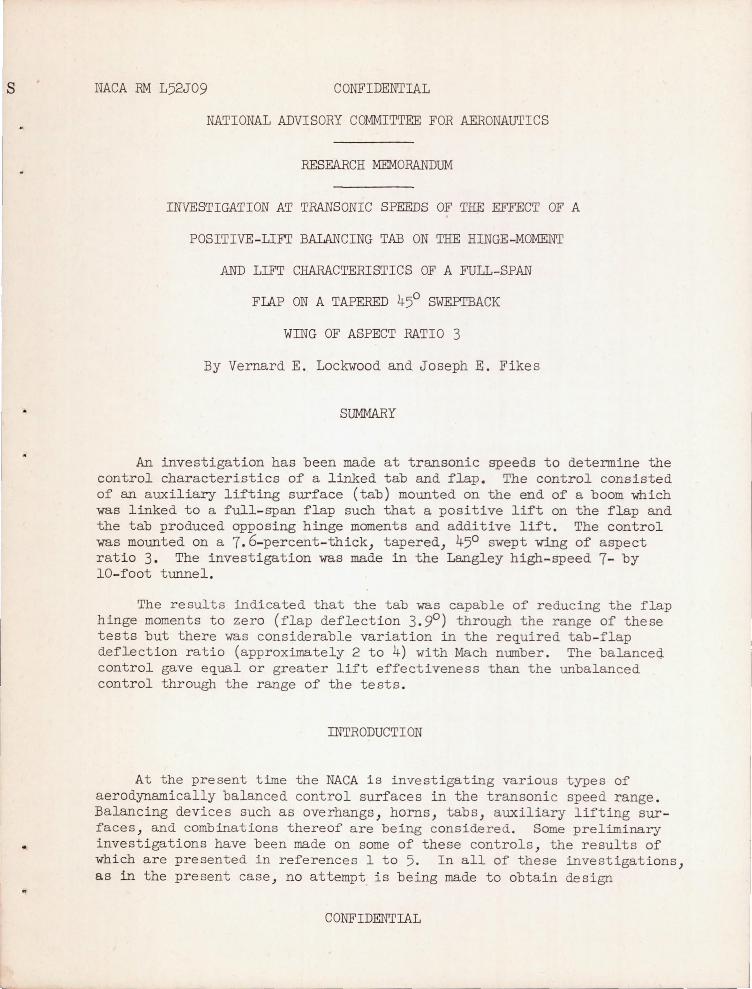
An investigation has b een made at transonic speeds to determine the control characteristics of a linked tab and flap. The control consisted of an auxil iary lifting surface (tab) mounted on the end of a boom which was linked to a full - span flap such that a positive lift on the flap and the tab produced opposing hinge moments and additive lift. The control was mounted on a 7.6-percent- thick) tapered) 450 swept wing of aspect rat i o 3. The investigation was made in the Langley high-speed 7- by lO- foot tunnel.
The results indicated that the tab was capable of reducing the flap hinge moments to zero (flap deflection 3. 90 ) through the range of these tests but there was considerable variation in the required tab - flap deflection ratio (approximately 2 to 4) with Mach number . The balanced control gave equal or greater lift effectiveness than the unbalanced control through the range of the tests .
INTRODUCTION
At the present time the NACA is investigating various types of aerodynamically balanced control surfaces in the transonic speed range . Balancing devices such as overhangs) horns) tabs, auxiliary lifting surfaces) and combinations thereof are being considered. Some preliminary investi gations have been made on some of these controls, the results of which are presented in references 1 to 5. In all of these investigations ) as in the present case, no attempt is being made to obtain design
CONFIDENTIAL
2 COl\TFIDENTIAL NACA RM L52J09
information. The emphasis is being placed, however, on finding whether the balancing device or combinations thereof appear promising at transonic speeds.
One method of balance which has been successful at low s~eeds and, from the data of reference 3, appears promising at high speed is the balancing tab. An undesirable feature of t he conventional balancing tab is the loss of lift of the control resulting from an oppositely deflected tab. The present investigation is concerned with a proposed balancing tab which would overcome the loss in lift usually associated with conventional tabs; that is, the lift of the tab would be additive t o the lift of the main control. The device is somewhat similar to one suggested by a representative of the Douglas Aircraft Company.
The control arrangement of the present investigation consisted of an adjustable auxiliary lifting surface mounted on the end of a boom which was linked to a full-span flap such that a po s itive lift on the f lap and the tab produced opposing hinge moments and additive lift. (In practice the adjustable surface could be a servocontrol.) The i nvestigation was made on a tapered, 450 swept wing of aspect ratio 3. The lift and hinge-moment characteristics are presented. The hinge moments measured were those of the flap-tab combination. The results are presented for an angle-of-attack range from 00 to 160 at a flap deflect ion of 3.90 from a Mach number of 0.70 to 1.10. The Reynolds number of the investigation was approximately 1,000,000.
S
b
M'
q
COEFFICIENTS AND SYMBOLS
lift coefficient, Twice semispan lift/qS
flap hinge-moment coefficient, Flap hinge moment about hinge line of semispan flap/q2M '
twice wing area of semispan model, 0.202 sq ft
twice semispan of model, 0.778 ft
mean aerodynamic chord of wing , 0.269 ft,
area moment of semispan flap rearward of the hinge line about the hinge line, 0.000692 ft 3
1 2 / effective dynamic pressure over span of model, 2PV, Ib sq ft
CONFIDENTIAL
NACA RM L52J09 CONFIDENTIAL 3
c local wing chord, ft
y spanwise distance from plane of symmetry, ft
p mass density of air, slugs/cu ft
v free-stream velocity, ft/sec
M lb / 2
2 cMady S 0
effective Mach number over span of model,
Ma average chordwise local Mach number
Mr local Mach number
R Reynolds number of wing based on c
angle of attack, deg
flap deflection relative to wing-chord plane, measurea in a plane parallel to plane of symmetry (positive when trailing edge is down), deg
tab deflection relative to boom measured in a plane parallel to plane of symmetry (positive when trailing edge is down), deg
boom deflection relative to wing-chord plane, measured in a plane parallel to plane of symmetry (positive when down), deg
CONFIDENTIAL
4 CONFIDENTIAL NACA RM L52J09
The subscripts outside the parentheses indicate the factors held constant during the measurement of the parameters. The parameters Ch and
f
°t CLOt were measured between approximately 00 and 16
0 tab deflection.
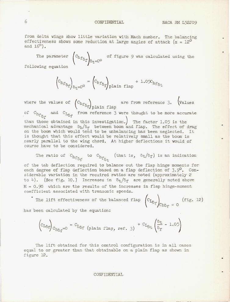
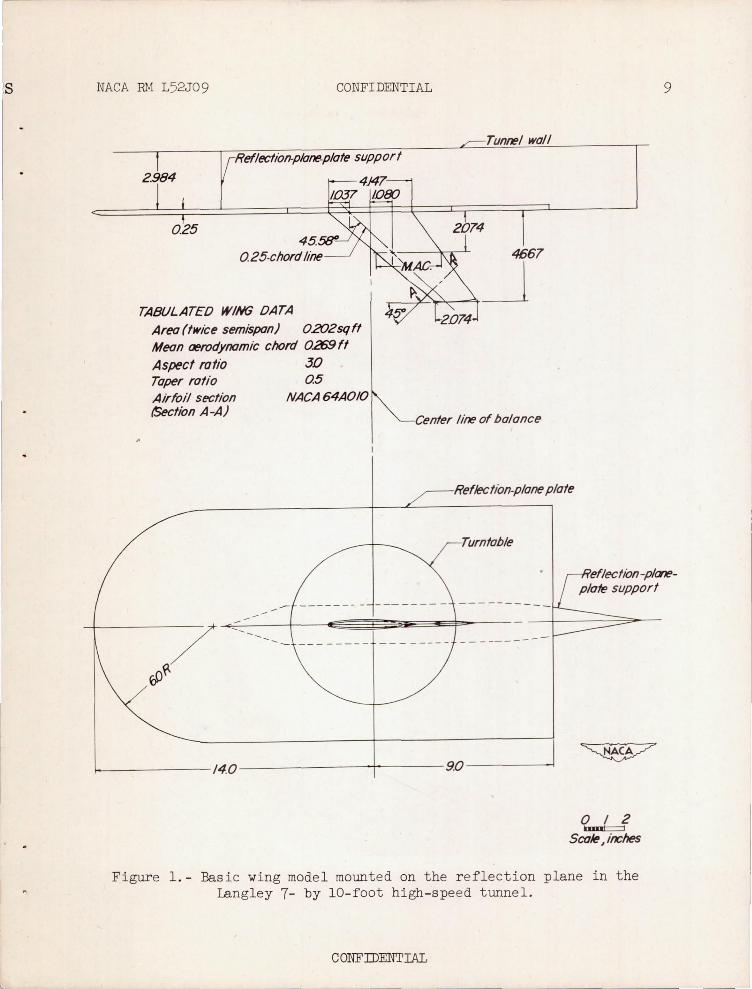
MODEL AND APPARATUS
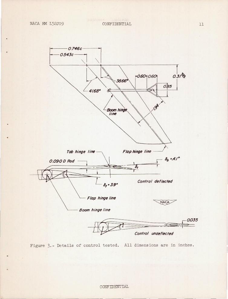
The steel semispan model used in the investigation had a quarterchord sweep angle of 45 . 580) an aspect ratio of 3) a taper ratio of 0.5) and was approximately 7.6 percent thick. The airfoil section was an NACA 64A010 measured in a plane at 450 to the plane of symmetry. The pertinent dimensions of the basic wing are given in figure 1 and a photograph of a typical wing mounted on the reflection plane is shown in figure 2 . The wing was equipped with a full-span plain flap-type control of 25.4 percent of the chord measured parallel to the plane of symmetry . The wing was also equipped with an aerodynamic balancing mechanism which consisted of a triangular auxiliary lifting surface (tab) mounted at the end of a boom which rotated about a hinge line ahead of t he flap as shown in figure 3. The b oom was linked to the flap so that a s the flap was deflected down the boom was deflected up (3.90 flap deflection = _4 . 10 boom deflection). The tab hinge line was located s llghtly ahead of the apex of the tab . In this case the tab was rigidly attached to the boom and was deflected positively. (In order to act as a balance the tab must be hinged to the boom and activated in a sense opposite in direction and at a greater rate of deflection than that for the boom. ) The tab area was approximately 6 .9 percent of the flap area. The hinge moments of the flap - tab combination were indicated by a straingage beam attached to the flap shaft . The model was mounted on an electrical strain- gage balance which wa s attached to the tunnel wall and shi elded from the air stream. The model butt extended through a turntab le in the reflection-plane plate with a clearance gap of about 1/ 16 inch. A sponge- rubber seal was attached to the turntable to
CONFIDENTIAL
NACA RM L52J09 CONFIDENTIAL 5
minimize leakage of air around the butt of the model. Tab deflections were corrected for angle changes due to deflection of the linkage under l oad .
TESTS
The tests were conducted through an angle-of-attack range from 00
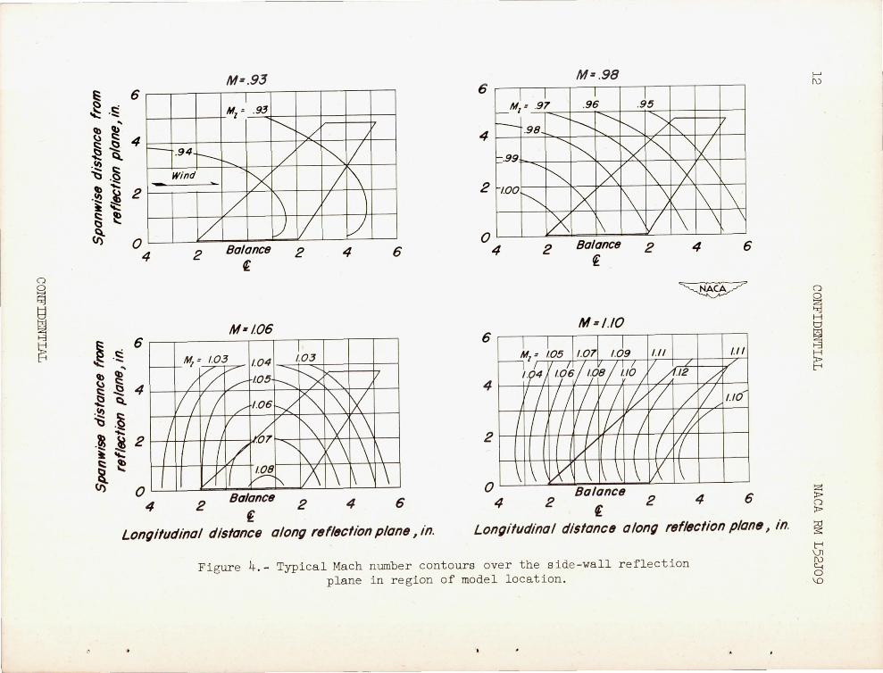
to 160 at a flap deflection of 3. sP with tab deflections from 00 to approximately 160 and over a Mach number range from 0.70 to 1 . 10 . For Mach numbers below 0 . 95 there was practically no gradient in the vicinity of the r eflection plane . At higher Mach numbers) the presence of the reflect ion plane created a local h i gh- velocity field which allowed testing the model up to M = 1 . 10 before choking occurred in the tunnel . Typical variations of local Mach numbers are shown in figure 4. The effective test Mach numbers were obtained from contour charts similar to those shown in figure 4, by the relat i onship
M = ~ lb/2 cMady S 0
For the investigation a chordwise Mach number gradient of generally less than 0 .02 was obtained between Mach numbers of 0.95 and 1.04, increasing to about 0.06 at the highest test Mach number of 1.10.
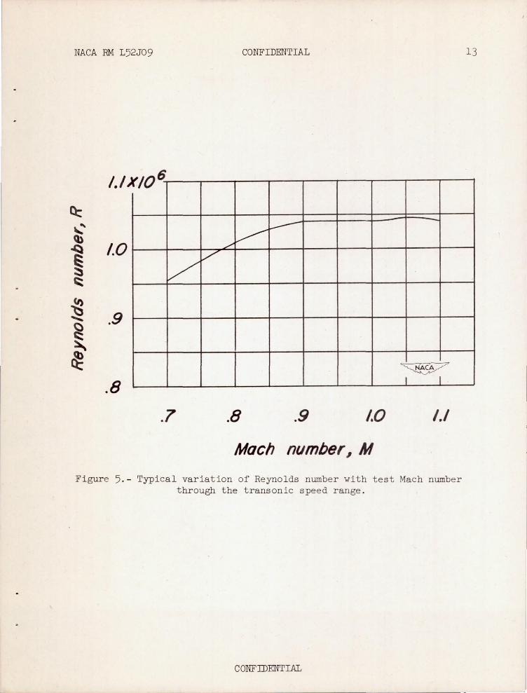
A typical variation of Reynolds number with Mach number is shown in figure 5.
RESULTS AND DISCUSSION
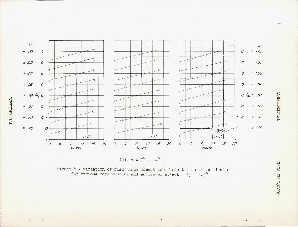
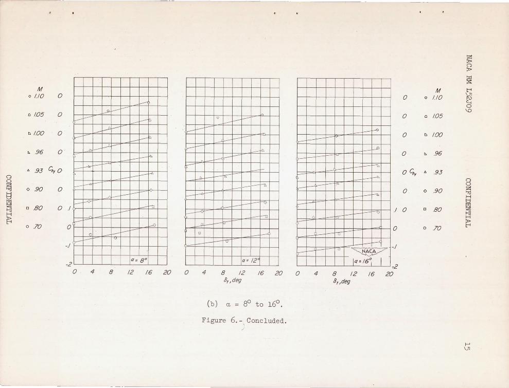
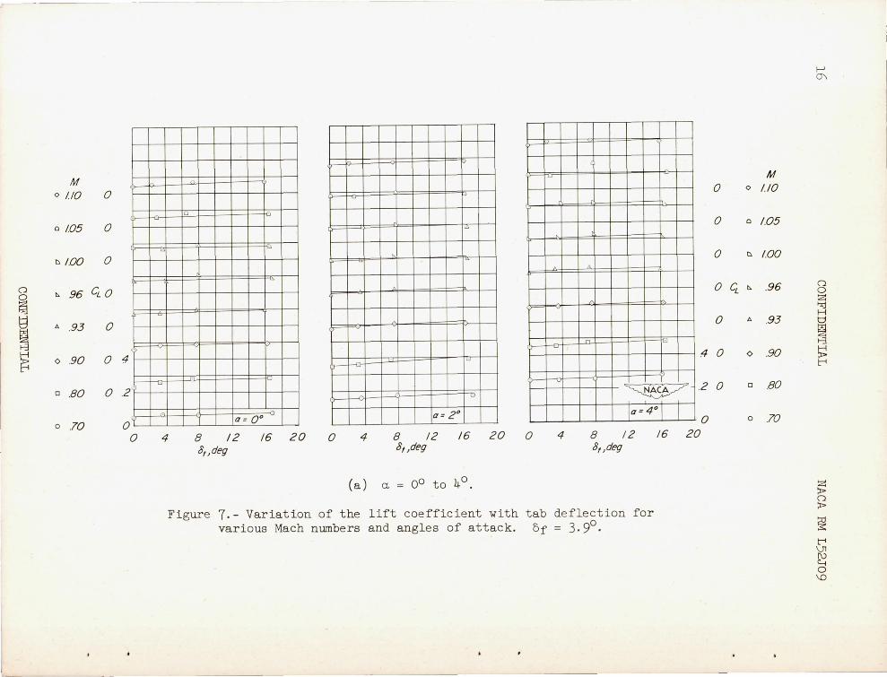
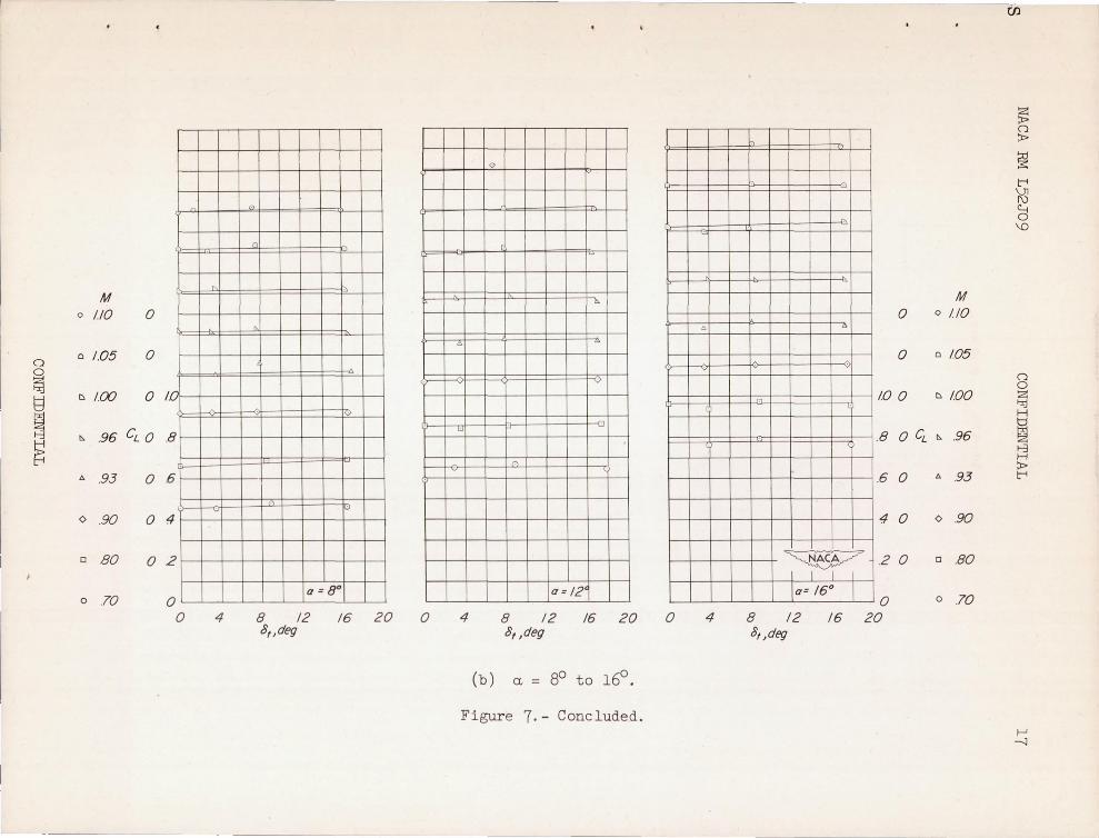
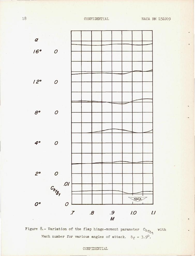
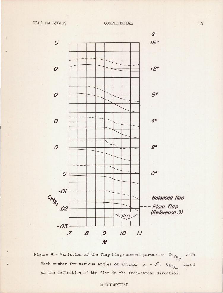
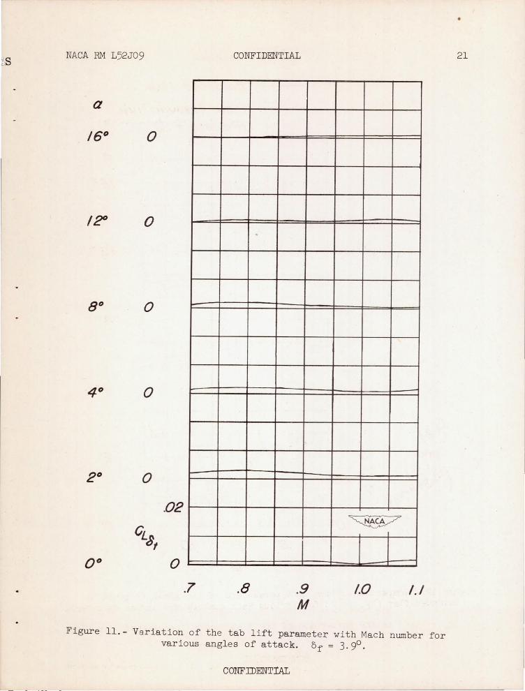
Variation of the flap hinge -moment and lift coefficients resulting from deflection of the tab are presented in figures 6 and 7 for a constant flap deflection of 3. 90 • The control parameters are presented in fig -ures 8 to 12. The parameters Chf and CL~ presented in figures 8
at ut and 11) respectively, are the average slopes of the coefficient curves against tab deflection between 00 and approximately 160 deflection. The flap parameter Chf (fig . 8) , which is a measure of the balancing
at effect of the tab) indicates that its effectiveness is approximately the same through the Mach number range . This might be expected since the tab is a 700 delta surface and lift - curve slopes and centers of pressure
CONFIDENTIAL
6 CONFIDENTIAL NACA RM L52J09
from de l ta wings show l i ttl e variat ion with Mach number . The balancing effectiveness shows some reduction at l arge angl es of attack (a = 120 and 160 ).
The par ameter of figure 9 was cal culated using the
fo l lowing equat ion
where the values of are from reference 3. (val ues
of ChfOf and CLOf
from ref erence 3 wer)e thought t o be more accurate
than those obtained in th i s i nvest i gation . The factor 1 . 05 is the mechanical advantage Ob/of between boom and flap . The effect of drag on the boom whi ch woul d tend t o be unbalancing has been neglected. It is thought that this effect wou l d be r e latively small as the boom is nearly paralle l t o the wing chord . At higher deflections it would of course have t o be considered.
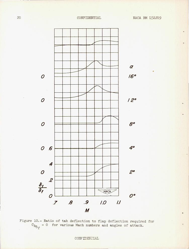
The ratio of Chf t o Chf (that is) at/Of ) is an indication of at
of the tab deflection required t o ba l ance out the f l ap hinge moments for each degree of f l ap deflect i on base d on a flap deflection of 3.9° . Con s iderab l e var i ation i n the required rat io s are noted (approximately 2 t o 4) . (See fig . 10 . ) I ncreases in at/Of are generaliy noted above
M = 0 . 90 whi ch are t he r esults of t he increases in flap hinge-moment coefficient associated with tran30nic speeds.
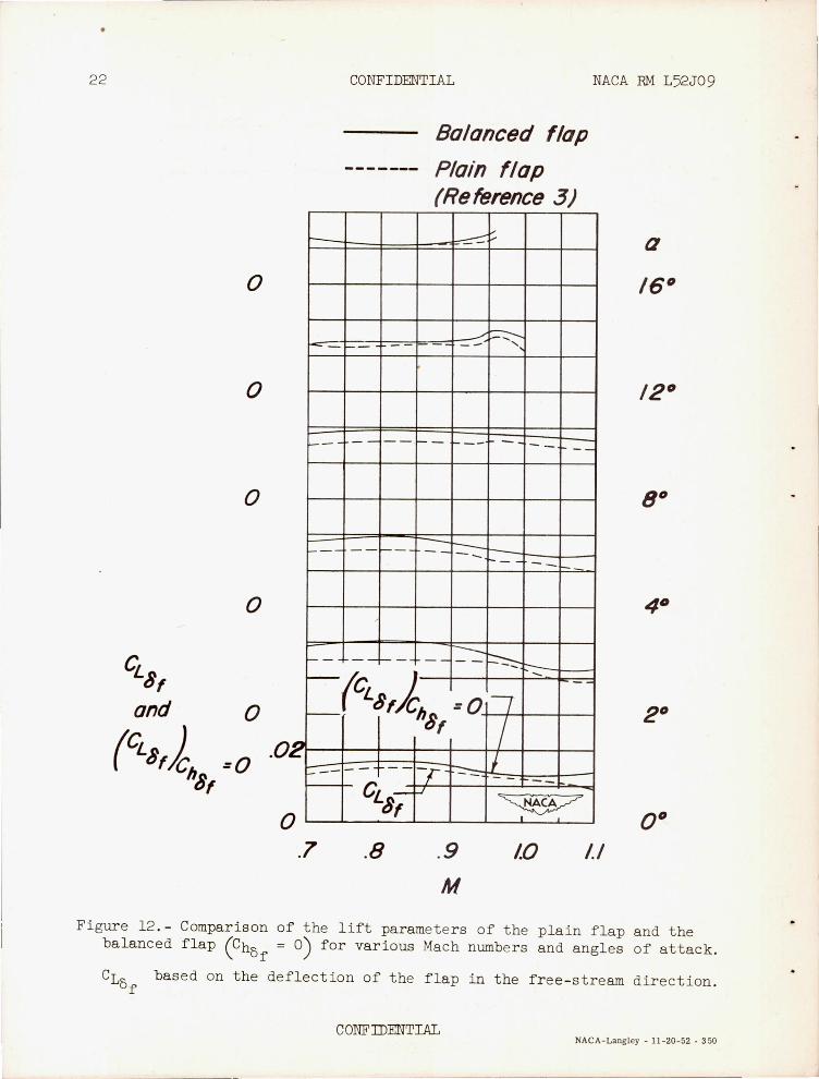
The lif t effecti veness of the balanced f l ap ( CLo ) (fig . 12 ) \ " f Cho f = 0
has been cal cul ated by the equati on :
The lift obtained for this control configuration is in all cases equal to or greater than that obtainable on a plain flap as shown in f i gure 12 .
CONFI DENTIAL
NACA RM L52J09 CONFIDENTIAL 7
It should be noted that the results presented herein should be examined from a qualitative viewpoint because the tab design does not represent a practical arrangement in that this tab arrangement was so located that it was possibl e t o deflect the boom in only one direction. A more practical arrangement of this balancing device would be to place the booms at the end of each flap and link the tab, boom, and flap through a gear train or other suitable linkage to obtain the required bal ancing action. Another arrangement would be a servo tab with the tab linked to the stick so that the pilot would control the tab deflection wh i ch in turn would control the flap deflection.
CONCLUDING REMARKS
An investigation at transonic speeds of a 7.6-percent-thick, 450 sweptback wing of aspect rati o 3 having a full-span flap set at a deflect i on of 3.90 and linked t o an auxiliary lifting surface indicated the following :
1 . The tab was capable of reducing the flap hinge moment to zero throughout the angle - of- attack and Mach number range tested.
2. The variation in tab- flap deflection ratios required for zero flap hinge moment with Mach number was generally small up to M = 0 . 90 but was considerably more at higher Mach numbers .
3. The balanced control gave lift effectiveness equal to or greater than that of the unbalanced control throughout the angle-of-attack and Mach number range tested .
Langley Aeronautical Laboratory, National Advisory Commi ttee for Aeronautics,
Langley Field, Va .
CONFIDENTIAL
8 CONFIDENTIAL NACA RM L52J09
REFERENCES
1. Lockwood, Vernard E. , and Hagerman, John R. : Aerodynamic Characteristics at Transonic Speeds of a Tapered 450 Sweptback Wing of Aspect Ratio 3 Having a Full- Span Flap Type of Control With Overhang Balance . Transonic-Bump Method. NACA RM L5lLll, 1952 .
2. Lowry, John G. , and Fikes , J oseph E.: Preliminary Investigation of Control Characteristics at Transonic Speeds of a Tapered 450
Sweptback Wing of Aspect Ratio 3 Having a Horn-Balanced Full-Span Control . NACA RM L52All, 1952 .
3 . Lockwood, Vernard E., and Fike s , Joseph E.: Preliminary Investigation at Transonic Speeds of the Effect of Balancing Tabs on the HingeMoment and Other Aerodynamic Characteristics of a Full-Span Flap on a Tapered 450 Sweptback Wing of Aspect Ratio 3. NACA RM L52A23, 1952.
4. Moseley , William C., Jr.: Preliminary Investigation of the Effects of a Paddle Balance on the Control Characteristics at Transonic Speeds of a Tapered 45 . 580 Sweptback Wing of Aspect Ratio 3 Having a Ful l -Span Flap-Type Control . NACA RM L5lL19, 1952. .
5. Lockwood, Vernard E., and Fikes , J oseph E.: Control Characteristics at Transonic Speeds of a Linked Flap and Spoiler on a Tapered 450
Sweptback Wing of Aspect Ratio 3 . NACA RM L52D25, 1952.
CONFIDENTIAL
.. --_._---
s NACA RM L52J0 9 CONFIDENTIAL
Tllnnel wall Reflectio~plane-plate SlIppor t
025
o 25-cllord line
TABULATED WING DATA
Area (twice semispan) 0.202sqft Mean aerodynamic chord 0.269 ft Aspect ratio 30 Taper ratio 05 Airfoil section NACA 64AOI0 rSection A-A)
Center line of balance
Reflection-plane plate
IIrntable
~----------- 140---------------4--------90 --------~
0 1 2 1111''' ' I
Sca~ , inches
Figure 1.- Basic wing model mounted on the reflection plane in the Langley 7- by lO- foot high- speed tunnel.
CONFTI)ENTIAL
9
· 0
~
i ~
'.
...
"
"
, .. iACA ."
• ~ .... 'j'
\ \ \ , ~ '.
..., - U( 3G8
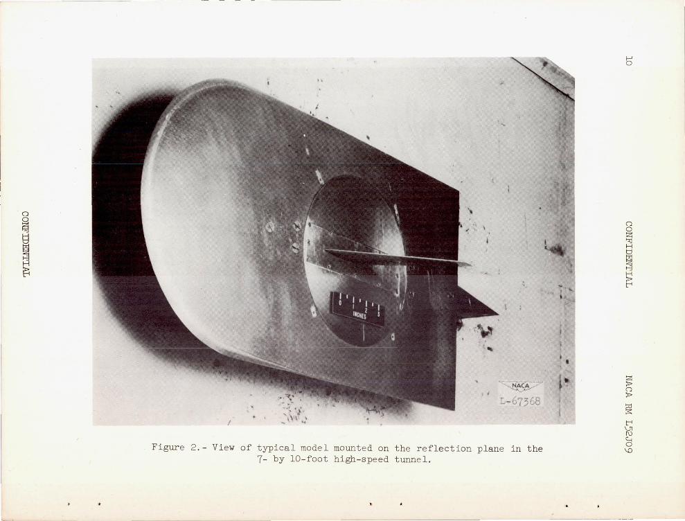
Figure 2 . - View of typical model mounte d on the reflection plane in t he 7- by lO-foot high- speed tunne l.
i • •
b
o o ~ f,;j H
~ t-3
~ t-<
s; o ~
~ t-< ~ ~ \0
NACA RM L52J09 CONFIDENTIAL 11
Tob hinge line Flop hinge line
Control deflected
Flop hinge line
800m hinge line
jl~ Control untle/leeted
Fi gure 3.- Details of cont rol tes ted . All dimensions are in inches .
CONFIDENTIAL
o
~ i f-3
~
~ . 6 ~ ·S ... ~ ~ § ~ 4 ....: ~ . (1)
i--
~ t;;: .~
'> ..... . (1) f.) 2 ~~ § ~ ~ o
4
~ . 6 ~ ·S ... ~ ~
--.94 --Wind ,.
/ 2
M= .93 1
Ml = .93
-- rx /
Bolonce {
M= /.06
~ '-./ / /
~ il / / \
\ / 1 /
) / / 2 4
1.03
c:: ~ 4 1 ~ ~ 1 / 1/ V ~ 'k' .::! r;;:: 7 }, ".I fl ~ ~ }
~ .~ ~ 2 I I I I II q ,.. 'to.;: • j u.: c:: ~
6
~ O I I I' y !' 1 I" II \ ! \ \
4 2 Balonce I ' 1 2 4 6
f Longitudinal distance along reflection plane, in.
Mz .98 6
.96
4 E'r9:ttL}J)k I i I
.991-- ......... 1 "j" 1/',1 h p, 1
2 ~1.O0 I 'i" V\[ I () \ I { \[ ~,
0 Bolonce 4 2 2 4 6
f.
~
M =1. /0
61 I I I I I I I 1,.,,1 , f . "",~ II . . ............ I • • __ I ,of """ FI / I . f~ I / / ,
4
I f/Yf f~+$1UO I r tTl-2
o I ' I r ' ! \ \ 1 , v
4 2 (
2 4 6
Longitudinal distance along reflection plane, in.
Figure 4.- Typical Mach number contours over the side -wall reflection plane in r egion of model location.
~
(")
~ H t::::1
~ f-3 H :x> t-'i
s; (")
:x>
~ t-'i Vl
~ \0
NACA RM L52J09 CONFIDENTIAL
I.IX 0 6 I
~ -..: Cb
1.0 ~ :::s c::
~ /
/"
V V
~ .9 ...... ~ ~
CC ~ .8 I I
.7 .8 .9 1.0 1.1
Mach number I M
Figure 5.- Typical va riation of Reynolds number with test Mach number thr ough the t rans onic speed range .
CONFillENTIAL
13
M
o 1.10 0
o 105 0
t:> 100 0
I>. .96 0
0 '" .93 r;, 0
~ o .90 0
i o .80 0/
~ 0 .70 0
-./ o
-----I---. .,..--V f.--"'
.,..--- I--"""
.r--!----~ ---- i
...--'. .---- I
~I-I--V
.J>-....--t
<- -V -f...-b-- --I--
~ - -I--!-----
I--f-o- ----j
V-O -I--
~ I--- ~ ----0
la=4° I I c/
4 8 /2 /6 20 o 4 8 /2 /6 20 o 4 8 /2 /6 20 8f ,deg 8f , deg 8f ,deg
(a ) Q = 0° t o 4° .
Figure 6.- Variation of f lap hinge -moment coeffic ient with t ab defl ection for various Mach numbers and angles of atta ck. Df = 3. 9° .
M 0 o I/O
0 o / 05
0 t:> /.00
0 I>. .96
o r;, '" .93
0 0 .90
0 0 .80
0 .70
I-' +=-
0 0 ~ I-:rJ H
§ ~ t-'
~ o :t>
~ t-' Vl
~ \0
0 0
~
I H
~
M o 1.10 0
01.05 0 k- --
D 1.00 0 y-
r:.. .96 O · ..t:-
Ii .93 c"f O· I--~ .
o .90 0 I-- .-<> -I--- -v
o .80 o ./
o .70 1.----1-
0
-./ t,.-
"2 o
C'
I--
4
1--.
...9---f--
__ I--- r;)
-P -- .,----- "' .-L - .r--
I.----I--fe. r-
I.----- I.----:::;;;;-
.- I---- I--
-- -cJ
--' -- ,---
.-Cl
- -I---u
0= 8 0
8 12 16 20 o
'" I----I---I---!--
Y I---!--
'<> -i---< .\--
I---"' -
=-- -~ I--I--re-
I--I--- ---z;
--fs -- I--I--- ~
.~
.-<:) - 1-0
...Jl - -0---
0 I-- f---<.
- - - -.:r
0= 12
4 8 12 /6 20 8t ,deg
(b) a = 8° to 16°.
Figure 6.- Concluded. , /
0
0
L-H--I1 L-+---\-'> 0
~ ~ 0
I--~
J--\--& o c",
L--J-+----tI ~
0
l---!--"
~ ./ 0
o .~
Frrff 0
-.1
Htttt~L o 4 8 12 16 20
8t ,deg
M o 1./0
o 1.05
D 1.00
r:.. .96
Ii .93
0 .90
0 .80
0 .70
~ o ~
~ t-+ M ~ \0
o o ~ H
i 8 H
~
f-' IJ1
M o 1.10 0
c 105 0
D 1.00 0
0 to 96 CL 0
~ ~ '" .93 0
8
~ ¢ .90 o 4
o .80 o:j o .70
0
L I ~ M 0 o /./0
0 c /.05
0 D 1.00
o CL to .96
0 '" .93
4 0 ¢ .90
~-
la:4° I I o I ~I I "J I lot .2 0 0 .80
o .70 4 8 /2 /6 20 o 4 8 /2 /6 20 0 4 8 /2
8"deq /6 20
8, , deq 8, ,deq
(a) a = 0° to 4°.
Figure 7.- Variation of the lift coefficient with tab deflection for various Mach numbers and angles of attack. of = 3.9°.
I--' <J\
0 0 2: f.:J:j H
~ 8
~ t"'"
~ o :t>
~ t"'" 'l\'j ~ o \0
0
<>
o
M '" o I/O 0
'" 0
o /.05 0
~ D /.00 o /.Oi ; b. .96 CL 0 .8 1-3
~ u
_f'L
I>. .93 o li
o .90 o 4
o .80 o 2
o .10 0 a = 8 0
a= /2
0 4 B /2 /6 8"deg
20 o 4 B /2 8, ,deg
/6 20
(b) a, = SO to 16° .
Figur e 7. - Concluded.
"
[.
o 4
M 0 o I/O
Q
0 o /.05
100 D 100
BOCL b..96
.6 0
4 0
~ 2 0 I I I I a= /6 0
B /2 o
/6 20 8"deg
I>. .93
o .90
0 .80
o .70
en
s; o ~
~ t-i
~ 2:l \0
0 0 ~ "l:j H
i 1-3 H ~ t-i
f--' -..:]
18 CONFI DENTIAL NACA RM L52J09
a
.01
o .7
-
.8
I--
.9 M
-
- --
---
r-------
I'--.... --~
I
1.0 if
Figure 8.- Variation of the flap hinge -moment parameter ChfOt
Mach number for various angles of attack. of = 3.9°.
CONF1J)ENTIAL
with
j
NACA RM L52J09
o
o ~
o
1- - -
o
e--
o
o
l-
-.03 .7
-- -
-
- - --
. -
. - I- --
.8
CONFIDENTI AL
-- t- __
~- --- t--
...... " ,
r---... ' ......
~ -- - -~
i--~ -- -...... , - 1--- - --
---- ~ r--- r---, "---- - t- -_
---r--
---r-- t--.- - ----- --
--...... r--- ---- - -t-__ -- t-, , - - Balonced flop
--......--.. '-....
~
- - - Plain flap (Reference 3)
I I
.9
M
10 1.1
Figure 9.- Var i ation of· the flap hinge -moment parameter Chf with Of
Mach number for various angles of attack. Ot = 00 • Chf bas ed of
on the deflection of the flap i n the free - stream direct i on .
CONF]])ENTIAL
19
20
o
o
o
o ,6
4
o .2
!L 8,
o
-
.7
CONFIDENTIAL
---
.8
/
V v
/ 7
.9
M
/'
v -
"'"
~ "-
v ~ ./
/
/ V
~
1.0 II
NACA RM L52J09
a
Figure 10.- Ratio of tab deflec tion to flap deflection required for Ch = 0 for various Mach numbers and angles of attack.
Of
CONFll)ENTIAL
!
~s NACA RM L52J09
a
/? 0
~
.02
o .7
CONFIDENTIAL
.8
I .9 M
~
/.0 /./
Figure 11.- Variation of the tab lift parameter with Mach number for various angles of attack. of = 3.9°.
CONFIDENTlAL
--_.!
•
21
•
22
o
o
o
o
Cts, and 0
(CLa,) =0·0 hS,
,I'll c
o
~
CONFIDENTIAL
Balanced flap
------- Plain flop (Reference 3)
--:::-::: ;...
---: ~ I- ....
-- -- I- - r-- - -
NACA RM L52J09
a
1--- --
I- - t---f--1--- --1-- - -- - ..... f- - - - - f-
,
I- r--~ 1-- --I-- -- t--
I-(CLa,lh =011 --
~ ~,/
7 r=--- - -r t--
cLS, -
f-I ~
.7 .8 .9
M
lO 1.1
Figure 12 .- Compar i s on of the l ift parameters of the plain flap and the balanced flap (Ch
Of = 0) f or var ious Mach numbers and angles of attack .
CLo based on the deflection of the flap in the free - stream direction. f
CONF IDENTIAL NACA-Langley - 11-20-52 - 350

SECURITY INFORMATION
CON FI DENTIAL
• '1
..
CON FI DENTIAL