Embed Size (px)
Citation preview

s. I t
RESEARCH. MEMORANDUM
E F F E C T O F FLIGHT SPEED ON DYNAMICS O F A TURBOPROP ENGINE
By S. Nakanishi, R. T. Craig, and D. B. W i l e
Lewis Flight Propulsion Laboratory Cleveland, Ohio
UNCLASSIFIED TO""""
NATIONAL ADVISORY COM-AAITT\; 7 - -~ I;
FOR AERONAUTICS ; . . . f i I .: lL,L,L,
'

RACA RM E55A05
NATIONAL ADVISORY COMMITTEZ FClR AERONAUTICS t
EFFECT OF FLIGEC SPEED ON DYNAMICS 03' A TURBOPROP EZTGINE
By S. Nakanishi, R. T. Craig, and D. B. Wile
Transient operation of a turboprop engine was inves t iga ted in an a l t i t u d e wind tunnel a t a simulated a l t i t u d e of 35,000 feet over a range of Mach numbers from 0.15 t o 0.5 t o determine the effect of f l i g h t speed upon the dynamic response of the engine. The step-input technique was used t o o b t a i n t h e response-of engine rotat ional speed to propel ler- blade-angle and fuel-flow disti~jbances. Values of time constant cal- culated from steady-state data&e compared w i t h resu l t s ob ta ined from harmonLc and semilog analyses.
The generalized time constant of the engine-propeller combination varied with f l i g h t speed and power level. The steady-state performance character is t ics of the propeller and engine were u t i l i z e d t o p r e d i c t the time constant a t various f l ight speeds, and the calculated value agreed with the time constant experimentally obtained from blade-angle transients. For both the blade-angle and fuel-flow inputs, the value of t h e time constant was invar ian t with direct ion and s ize of disturbance t o &lo percent speed changes.
U
In the design and ana lys i s of an automatic control system f o r a gas- 1 turbine engine, knowledge of the t r ans i en t performance characteristics of the engine, together with a p r a c t i c a l method of expressing these c-ac- 4 teristics, is desirable. As an i n i t i a l s t e p t m r d t h i s end, a mathematical expression of t he t r ans i en t r e l a t ion between various input and output engine var iables a t a given operating condit-lon my be formulated. Understanding the transient engine behavior over a broad range of engine operating condi- t ions then requires a knowledge of the var ia t ions in t he coe f f i c i en t s of t h e basic mathematical eqression caused by v-ng f l igh t condi t ions o r power sett ings. Although experimental t rans ien t inves t iga t ion of a given englne direct ly renders the t ransient performance character is t ics a t the conditions
any engine at any f l igh t condi t ion by c<lculation f r o m steady-state per- formance maps is a highly usefu l t o o l i n cont ro l synthesis and design.
i investigated, a reliahle method of predictfng the t r ans i en t performance of
* . -
2 NACA RM E55A05
From previous investigation6 on turboprop engines (refs. 1 to 3), "
the transient response wa8 found to be first order and linear for &lo- f
percent .change in speed over the entire operating speed range. In reference 1 the time constant of the engine-propeller combination cal- culated from steady-state performance characteristics W ~ S found to agree very well wlth the time constant obtained experimentally. Furthermore, the generalized values of time comtant were invariant over a range of pressure altitudes. The static sea-level investigation of reference 3, indicates agreement between calculated and experimental time constants within 14 percent. Because both investigations were conducted at con- , F- stant flight speeds, the effects of flight speed on transient performance .' ro
. R were not determined. The purpose of the work reported herein was to develop a method of facilitating the prediction of englne responee time in order to study the effects of flight speed on the dynamics of a turboprop engine. In addition, information on the degree of reliability of such a method of calculatim. was &esired.
. I.
"
In order to achieve these objectives, experimeatal studles were made of the response of engine rotational speed to fuel-flow and propeller-blade-angle disturbances. The investigation covered transient performance at a simulated sltitude of 35,000 feet over a range of flight Mach numbers from nominal values of 0.15 to 0.5. By utilizing the steady- state characteristics and the calculation method presented herein, the variations in transient performance with flight speed were predicted. 9 . Relative effects of propeller arid engine upon the transient performance at various flight speeds were studied. The extent to which the engine held to a linear first-order response as well as to the quasi-static assumptions on which the calculation method is based was then determined by comparison of the calculated and experimentally obtained time constants. .
. - ..
e
Because of the different manner in which f l i g h t speed affects the propeller and the engine, the dynamic characteristics of a turboprop en- gine cannot be expected to generalize. However, standard generalized forms are used to present all -results an a comparable basis.
ANALYSIS
The exact mathematical description of the dynamics of a gas-turbine engine leads to equations whose solutions are erctremely difficult to obtain. The general approach, therefore, is the representation of the system dynamics by linearized differential.equations for excursions of limited size about a steady-state operating p o i n t . Equations thus ob- tained are more readily solved so that the response of rotational speed, say, of a turboprop engine to a finite disturbance in propeller blade angle can be amply described. .

The solution of a differential equation that describea the transient response of a first-order linear system is characterized by a system time constant. Tne analytical determination of the time constant is ac- complished by substituting proper coefficients into the equation defining the time constant. These coefflcients or gains are a measure of the engine’s sensitivity of one variable in response to another variable. The quasi-static assumptions of a linearized dynamic analysis state that these gains can be obtained from the slope, at a given operating point, of a steady-state performance curve of the one variable plotted as a function of the other.
The prediction of time constant over a range of flight speeds thus requires a steady-state performance map of the desired variables at each flight speed. In the event that such maps are unavailable for all the conditions desired, a generalization and extrapolation technique or some other method must be utilized to obtain the necessary information.
The following am1ysis.i~ devoted to a coqsideration of the turboprop- engine variables pertinent to calculation of the time constant. A method is also developed whereby the prediction of the time constant in the absence of sufficfent steady-state performance data can be accomplished.
Previous work on turboprop engines indicates that at a given flight condition the response of engine speed to fuel flow at a constant blade angle is
where S is the Laplace operator and denotes the derivative =. Suitable use of gear ratios permits the use of engine shaft speed in this equation. The definitions of symbols used throughout the report are given in appendix A.
d
Similarly, fuel flow is
the response of engine speed to blade angle at constant

4 MACA RM E55A05 ?
Both responses have the same associated time constant, napely, #
T=m 1, 4- I'
The partial derivative (sJw, a l s o c,alled the torque-speed gain
a t constant fuel flow, can be readily evaluated as the slope of a curve defining torque as a function of engine sgeed during constant fuel-flow operation. In lflre manner, the torque-speed gain a t constant blade angle
(r!
.. .
(%JP can be evaluated from operation a t a constant propeller blade
angle. I n t h i s manner, equation (3) was used in ob ta in ing the calculated t i m e constant. Full development of the preceding equations is given I n reference 1.
Propeller Dynamics
I n the analysis of propeller dynamics,-the propeller torque a t con- d
s t an t a l t i t ude and r a m pressure is generally considered t o be a function of blade angle and speed:
It is found in r e f e rence 1 that a t d i f f e ren t a l t i t udes the blade angles and steady-state torques identified with a given corrected engine speed and corrected tail-pipe temperature were not ident ica l . The slopes
of the generalized torque-speed curves a t a given engine
speed, however, were found t o be practically independent of a l t i t ude . The dynamic response of the propeller, therefore, could be generalized f o r a range of a l t i tudes , even though the steady-state performance did not completely generalize.
As the propel ler is operated at d i f f e ren t flight speeds, the values of propel ler blade angles used in maintaining the engine speed and power within normal operating range w i l l vary wldely. Depending upon the cha rac t e r i e t i c s o f - the propeller, the torque-speed function and hence
will normally vary i n a manner much d i f f e ren t from that found
. .
(%Ip J during a l t f tude changes. To predict the propel ler dynamics under such conditions requires a descr ipt ion of the propel ler hharacter is t ics over the enter range of f l i g h t speeds encountered. I

NACA RM E55A05 L
5 , ..P
Y The variables affecting propeller performance can be grouped i n dimensionless parameters. Two of these parameters, -the power coef f ic ien t and the advance r a t i o , have a func t iona l re la t ion that forms a fami ly of l i n e s WFth a th i rd parameter, t he blade angle. From such a performance map, it is possible to determine the torque-speed characterist ics at any specif ic f l ight condi t ion by select ing the values of f l i gh t va r i ab le6 pecul iar to that condition.
w Assuming that the p rope l le r power coef f ic ien t at a given propeller w blade angle can be represented by a second-degree polynomial in - u1 4
v o r advance ra t io , g ives %%’
Referring t h e propeller torque t o engine shaft speed, combining constants, and taking partial derivatives with respect t o engine speed Ne give
By taking Into account the gear-box losses, which are included i n t the torque measurement, the equation becomes
b (g)p = (I + fy aM + 2573-5 (7) B NE
where (2) is defined by equation (6 ) . Detailed developnent of these e!3
equations is’ e v e n i n appendix B.
Engine Dynamics
I n a d d i t i o n t o the use of the propeller torque-speed information previously discussed, engine torque-speed information is needed f o r t i m e - constant calculation. If available experimental data can be properly generalized, the torque-speed characterist ics can be extrapolated for conditions of operation n o t covered by the experimental data.
Previous investigations on t u r b o j e t engines indicate that the bas ic gains of the engine i tself can be general ed by use of standard parameters (refs. 4 and 5) . The generaliza€ion of , which i s an engine func- k)w - t ion, is therefore considered suff ic ient ly correct over the range of sub- son ic f l i gh t Mach numbers covered In the present invest igat ion.
6 - NACA RM E55A05
In summary, the analytical det tion of the h e constant re- quires the evaluation of the two gaq$-p and (%Jw at a steady- rn
state aperating point.where the rotatima1 speeds and the torques of the propeller and the engine are -matched. At simulakd~i”igEt conditions where the neceesary steady-state experimental data are ivailable, the torque-speed gains are readily evaluated fr& -st&ady-s%te performance maps. For operating regions where experimental performance data are unavailable, torque-aped gains at constant blade angle, evaluated from PC the propeller characteristics curve-s, and extrapolated values of torque- pr
VI speed gains at constant fuel flaw &re used to p r e a c t the time constant. rQ
.. . ..
. ..
. -. . . . . ..r - - ” 1
APPARATUS AND INSTRUMENTATIcmT
Wind-Tunnel Installation
-
The turboprop engine was wing-mounted in the 20-foot-diameter test section af the NACA Lewfs -altitude wind . tunnel as shown in figure l(a) . The tunnel had facilities for simulati~ig flight coxiditioIis at a .steady- state operating point by controlling air temperature, air speed, and al- tFtude pres-sure. . A n exhaust-gas swap located dawnstream of the engine removed hot ezhaust gases - f r o m the tunnel s3xeam.’
. .
Engine and Propeller
The turboprop engine had a nominal static sea-level rating of 2520 shaft horsepower and-a jet thrust of 603.poun-aS akmilitary operating conditions. A schematic drawing of the engine is shown in figure l(b) . The main components included -a 19-stage axial-flow conpressor, eight cylindrical can-type combustors, a -four-st@ge turbine, and an exhaust cone. The engine w a ~ connected-through a 12.5:l rduction gear box to a 13-foot-diameter three-bladed propeller.
Input Systems
Input disturbances in f u e l flow were Imposed by a separate -fast -
acting valve and regulator. Blade-angle disturbances were accomplished by a modified engine -servo system.
Instrumentation
. . . ., * .
a
Instrumentation on the test installation UBB designed to measure and &
record transient data as well as steady-state data at the end point8 of the transient runs. The steady-state and transient Fnstrumentatlon used
3

NACA RM E55A05 r
7
Y in the inves t iga t ion are listed i n table I. moper design and fabrica- tion techniques w e r e incorporated to obta in the desired accuracy and frequency-response characterist ics. All t r a n s i e n t data were recorded on direct- inking s t r ip-chart osci l lographs with a s s o c i a t e d . m p l i f i e r s f o r each channel.
PROCEDURE w UI CH Desired f l ight condi t ions were simulated i n the a l t i t u d e wind tunnel 4 by s e t t i ng t he air temperature, tunnel a i r speed, and a l t i tude p ressure .
For transient runs involving fuel-flow disturbances, the propel le r blade angle was set a t a given wlue and fuel f low was increased or decreased in s t e p s i z e s necessary to ob ta in the desired engine-speed change. Engine power level was varied by s e t t i n g d i f f e r e n t va lues of the blade angle.
Transient runs with blade-angle disturbances w e r e made by maintaining constant f u e l flows of various magnitudes while the blade angle was in- creased or decreased to obtain the desired terminal speeds.
Both types of input disturbances w e r e made to cause increases and decreases in the engine rotat ional speed. Steady-state data w e r e taken a t the beginning and end of each t r a n s i e n t after engine operating con- d i t i ons had reached equilibrium. <
a
RESULTS BM3 DISCUSSION
The time constant characterizing the t r a n s i e n t speed response of the turboprop engine was calculated from equation (3) as set f o r t h i n the ANALYSIS sect ion. The steady-state experimental information used i n t h e development of the ana ly t i ca l method is presented herein followed by a presentation of predicted time constant and a discussion of the e f f e c t s of f l i g h t speed upon t h e dynamics of the turboprop engine.
Time constant was a lso eva lua ted experhenta l ly from a study of t r ans i en t changes i n engine rotational speed following a d is turbance in fue l f low or p rope l le r biade angle. The experimental results a r e com- pared with the-predicted values t o check the r e l i a b i l i t y of the calcula- t i o n method and the msumptions of a f i r s t - o r d e r l i n e a r system.
In the fol lowing discussion, a t tent ion i s of ten d i rec ted to the propeller and the engine ae individual components or to the tu rboprop engine as a unit. For the sake of c l a r i t y t h e y w i l l here inaf te r be d i f f e ren t i a t ed and referred t o as the propeller, the engine, and the - engine-propeller combination or, simply, combination.

8 - RACA RM E55AO5 f
Calculation of Time Constant for Engine-Propeller Canibination
As stated i n the ANALYSIS section, the torque-speed characterist ics s
o r the slopes of the torque-speed curve a t constant blade angle and again a t cons tan t fue l f low were needed t o comglete the &lcula t ion of the -
combination time constant. In both cases, the steady-state torque-speed curves were based on the measured o r shaft torque and hence included the gear-box loeses . "
"6 =
The propel le r charac te r i s t ics were based on the torque of the pro- peller alone. Equations w e r e dq iyed . to accoun t fo r the gear-box losses, however, so that the values of shaft torque c ~ ~ ~ t - ~ ~ f r ~ ~ " e q ~ a t i o n ~ ~ B I O ) of appendix B w e r e consis tent with-the eqe r imen ta l ly measured torque.
Propeller charac te r i s t ics . - The generctllzed propeller characteris- t i c s are presented i n f igu re 2, where the pawer coef f ic ien t C i s p lo t t ed against the advance r a t i o Y/N$ . A t each blade angle the power coef- f i c i e n t was defined as a dis t ince funct ion of the advance r a t i o . Blade- angle l ines without experimental data points were located by interpola- t i on . The l i nea of constant blade angle were near ly parallel a t high advance r a t i o and high blade angles, but a t lower blade angles and ad- vance r a t i o , the slope of the lines decreased. The e f fec t upon the propeller torque-speed gain may be seen by considering each variable in
t he power coefficien tn i ch are,
"P ana - nv Ly, n5r;l;i2 D A L when referred t o the engine shaft.
A t a given altiGude and nominal engine speed, air densi ty p snd engine speed Ne me constant. S h i f t i n g t o a lower ve loc i ty V along a constant-blade-angle line moves the power c o e f f i c i e n t t o a higher value where the s lope of the curve decreases. Similarly, s h i f t i n g t o a lower veloci ty a t a constant value of the power coef f ic ien t requi res that the blade angle change from higher t o lower values, which again results i n curves with less slope. The propeller torque-speed gain
varies with veloci ty V in a manner similar t o the power coeff ic ient , thus decreased with decreasing fligh-t speed.
( %&J which
It was found that the power c o e f f i c h a t &. this propel ler a t a given blade angle could be ex-gressed emgir icauy by a second-degree polynomial of the general form - . ". . . - . ." .. . . " . - . . . . . -
where a, b, and c are constants for a given blade angle a8 tabulated
"
1

NACA RM E55A05 0 9
w cn CIJ 4
'1
A
in table 11. F r o m the equation for power coefficient, the equatLons for propeller torque and its first derivative with respect to engine rota- tional speed were derived. Including the gear-box losses as described i n appendix B, the final equations (B10) and (B11) made possible the
Torque-speed operating -2. - The slope of the steady-state torque- speed curve for constant blade angles should be evaluated from data taken at constant flight conditions or at conditions identical to those from which the corresponding constant fuel-flow torque-speed data were obtained. The tunnel air speed varied, however, as the engine speed varied from one steady-state value to the next, and it varied in dissimilar ways during constant-blade-angle and constant-fuel-flow runs. The dissimilarity of tunnel air speed made it necessary to correct the experimental data taken during constant-blade-angle runs before a torque-speed operating map could be drawn.
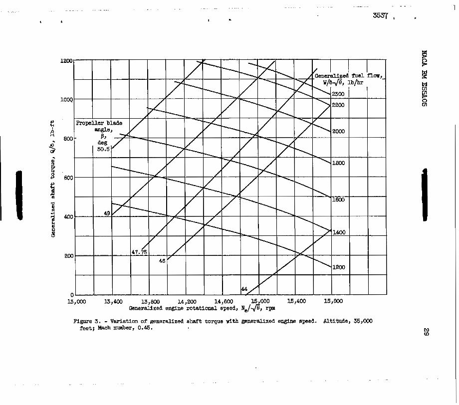
The torque-speed characteristics fulfilling the requirements of identical simulated flight conditions during constant-fuel-flow and constant-blade-angle operation at an altitude of 35,000 feet and a Mach number of 0.45 are shown in figure 3. The lines of constant corrected fuel flow were obtained from steady-state data taken at the end points of blade-angle transients. The lines of constant blade angles were ob- tained from equation (~10) for shaft torque. Values of p and v used in the equation corresponded to those encountered at each engine speed during the constant-fuel-flow runs. The slopes of the constant-blade- angle lines Z@ and the slope8 of the constant-fuel-flow lines
(&& $ provided the necessary information for calculating the com-
bination time constant at this flight condition.
(%IB 6
An examination of figure 3 indicates the probable trend to be ex- pected in the values of the calculated time constants. The lines of con- stant blade angles are nearly straight and parallel. Hence the values of
6 fi are n e a r l y equal for all blade angles-
The lines of constant fuel flow are lines of approxfmstely constant power input or shaft horsepower. Because shaft horsepower is the product of torque and rotational speed, the value of shaft torque decreases as engine speed increases with fuel flow held constant. The slopes of the constant-fuel-flow lines are approximately equal for all values of cor- rected fuel flow and are also relatively small compared with the slopes

of the constant-blade-angle lines. The s u i of €he two slopes
and (- &-& $, therefore, remains almost constant over the en t i r e
range of shaft horsepower. Consequently the calculaked time constant may be expected t o be almost invariant d t h shaft horsepower at the 35,OCD- foot, 0.45 Mach number condition. - -
(%Jp + " I. I _ _ . -
Evaluation of the torque-speed gains requi red for the-cons tan t calculation a t flight Mach numbers other than 0.45 differed in procedure because insufficient constant-fuel-flow data precluded the plott ing of
torque-speed operating maps. The values of the gain
from figure 3 were p lo t ted against generalized engine speed as shown In f igure 4 . On the basis of extensive turbojet-engine experience (e.g., refs. 4 and 5 ) , the assmptlon was made that gains describing the re- sponse of- the e n g ~ e operating a t constant a l t i tude general ize fo r dif - fe ren t Mach numbers with the use of 6 and 8 . This assumption was borne out by the limited amount of canstant-fuel-flow gain data obtaliied at various flight speeds and shown p lo t ted i n figure 4 . A single curve is faired for the entire range-of corrected fie1 flows and f l i g h t Mach
numbers covered. This curve provided the engine gain (- %& *.
(a)w obtained
m e p r o p e l l e r gain at various flight speeds WSB calculated
by using equation ( 7 ) and subst i tut ing sui table values of V, p, and X, for a gfven blade angle. The w e r a l i z e d v a l u e s of the p ro e l le r ga in
thus calculated together with t he engFne gains (- %lW =@' from figure
4 provided the necessary Information to ca l cu la t e the time constant of the engine-prapeller cmbjnation operating a t flwt Mach numbers of -
0.15, 0.3, and 0.5 a t an al t i tude of .35,000-Peet .
Calculated time constant. - The calculated time constant of the engine-propeller canhination in general ized form-is plot ted against generalized shaft horsepower in figure 5. The calculated points are Included t o show the degree of-scatter given by the calculation tech- nique. Flight Mach number had a marked e f f ec t on the value of the time constant. The e f f ec t s of propeller blade azigle -ma rotationaL speed combined, within limits, t o mahe the engine tbe constant anly a func- t i on of shaft horsepower at any given Mach number. The operational power level apparently had l i t t l e e f f e c t upon the combination time con- s tan t a t high k c h numbers, but the effect beceiw mare noticeable as flight speed decreased. -.
. . . . . . . . . . . . . . . . . .
"
. "
"-
L
" - . "
. .. "

w UI 4 w
03 s i
c
NACA RM E55805
Another view of the var ia t ion in time constant with bkch number and power l e v e l is shown in f igure 6, where the information of f igu re 5 is cross-plotted a t values of constant shaft horsepower. The time constant increased 200 to 280 percent as the Mach number decreased frm 0.5 to 0.15 with the larger increase occurring at the low power l eve l .
Lnasmuch as these values of time constant are calculated from equa- t i o n (3), the var ia t ions in the time canstant w i t h power l e v e l and w i t h flight Mach number can be t r a c e d t o similar variat ions in one or both of
the (- %!JW a 6 -($)@ dE. 6 me variat ions in engine torque-
speed g a b (- g)w $ a re shown i n f igure 4 t o be a function only of
engine speed. Because the englne was operated aver the e n t i r e normal range of rotat ianal speed a t any g i v a flight Mach number, any var ia t ion
i n time constant caused by the var ia t ions in ($)w $ w o u l d be ex-
pected t o appear at a Mach number of 0.5 as well as at a Mach number of 0.15. Figure 6 shows, however, that the value of time constant was prac t ica l ly invar ian t at Mach 0.5. The dissimilar var ia t ion of the constant 'wi th power l e v e l a t Mach nmbers of 0.5 and 0.15 must therefo e r e su l t from a corresponding variation i n the propel ler gains
It is s-icant to note that the cafbination t- c o r n t a t depends upon ths sum of the e n g h e gain and propeller gain, and therefore the rela- tive numerical magnitude of the two . gains is also an inqortant fac tor .
(%JP =#
The generalized torque-speed gain of the propeller calculated from equation (7) is shown in f igu re 7 p lo t ted against generalized engine speed for various values of blade angle. The two blade-angle l ines ident i f ied with the same symbol denote the approximate upper and lower values of blade angles covered during operation at that flight Mach nun- ber. The low blade angles were associated with the low flight speeds as were the high blade angles with high speeds. A t any given f l ight speed the higher blade asgle was associated with the high-shaft-horsepower operation. The var ia t ion in the gain due t o a change in engine speed at any given blade angle did not exceed 9 percent over a corrected speed range of Zoo0 rpm. A t a Mach nwnber of 0.15 the var ia t ion i n g a b due t o the change in p o v r l e v e l s , that is, a change in blade angle, was about 47 percent a t 15,000 r p m . . A t the same engine qeed but at a Mach number of 0.3, the var ia t ion was reduced t o 20 percent; at Mach 0.45, 8 percent; and at Mach 0.5, p rac t i ca l ly none. Thus the torque-speed gain of the propellek. varied considerably with power l e v e l a t the l o w Mach numbers and only s l i g h t l y a t the hi&h flight speeds, which is cmsistent with the var ia t ion i n the generalized time constant.

12 0 NACA RM E5305
Because the time constant varies with thessum of the two gains - (- $)w 9 and (%)@ $, their r e l a t i v e n u m e r i c i values indicate
the re la t ive e f fec ts they have q o n the c d i n e d response, a6 well as the predominance of one over the other at various operating conditions. A t the higher Mach numbers, t he propeller charac te r i s t ics governed the var ia t ions in the value of the g er ized combination time constant, because incremental changes in raw $, which is numerically s m a l l
compared with a f fec t the sum of the two gains but slightly.
A s the air speed V increased, but the propeller rotational speed re- mained within a limited range, the propel ler blade angle was obliged t o vary Fn a manner such that the power requirement of the propeller matched the power avai lable from the engine. The propel ler such that at the higher W h nmibers the propel ler
tendency t o approach a common value as shown i r . f i g u r e 7 . The constant magnitude of the propeller gain irrespective of power l eve l caused the time constant to likewise approach a camon value as shown in figure 6 .
A t low f l i g h t speeds and corPespondingly low blade angles, the en- gine gain and propeller gain were ahout equal in maapitude. Because shaft horsepower i s a function of rotational speed and torque, the vari- at ion of engine gain with r o t a t i o m l speed and the var ia t ion of propeller gain with blade angle ( OT torque level) combined t o cause the vaxiation in time constant with power l e v e l - a t low Mach numbers.
The foregoing discussion also demonstrates the reason why the turboprop-enghe time constant over a m g e of fUght speeds does not genera l ize to a single curve when a parameter such as €i/G is used. Flight speed and the attendant blade-angle change have d i s s W e f fec t s
on the propel ler e-311 and the engine gain (- g)w. Thus the
gains themselves as w e l l as. the sum of the two gains do not generalize t o a single curve when a s ingle parameter is used.
rJi3 In contrast to the turboprop engFne ia the case of the turbojet
engine. A s pointed out in reference 5, the .const@nts of the t ransfer functions, that is, gains and time constant a t various altitudes and flight. Mach numbers,' generalized t o one curve at standard static sea-. level conditions.
An examination of equation (3) sham that genera lha t ian of the time constant of the engine-propeller combination to a shgle curve w i l l require parameters which. can be applied to. t he . pmpe l l e r gain and
I
z
F

13 NACA RM E55A05 I
the engine gain separately such that t h e SM of t h e two gains evalwted w at different flight speeds will generalize t o a, single curve.
Determination of T h e Constant from Transient Tests
Time constant evaluated from transient operation provide, by com- parison with ca lcu la ted resu l t s , va l ida t ion of the calculat ion method of obtaining the combination time constant.. In the ca lcu la t ion method, t h e engine is assumed t o be a quas i - s ta t ic s y s t e m over the frequency
and order of the response, can a l s o be determined from studies of the r e s u l t s of t h e two methods.
w cn w 41 range considered. Departures from this assumption, as well as the type
Because of jn te rac t ion of the turboprop engine and the wind tunnel, changes in engine operat ing speed caused dynamic v a r i a t i o n s i n the simu- l a t e d t u n n e l f l i g h t speed during a t r ans i en t run. The effects of this in te rac t ion were taken into account in order that the calculated and experimental v a l u e s of the time constant may be comparable. The method of correct ion for f l ight-speed var ia t ions and the effects upon response t i m e are given in appendix B.
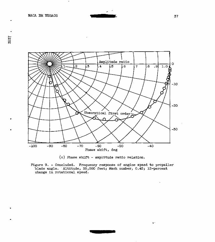
Blade-angle disturbances. - A typical recording of the t r ans i en t - response of the engine t o a d is turbance in the p rope l le r b lade angle is shown i n f i g u r e 8. Engine f u e l flow, propeller blade angle, torque, rotat ional . speed, turbine- inlet to ta l temperature, and tunnel dynamic pressure a re the variables shown. This par t icular response w a s t yp ica l of t h e fastest d is turbances a t ta inable in blade angle and obviously did not approach too c lose ly a step disturbance. Bzcause s tep inputs were not attainable, semilog analysis could not b e u t i l i zed . Ins tead , harmonic analysis with the aid of mechanical d i g i t a l computers w a s performed t o obtain the frequency-dependent engine characteristics (ref. 6 ) . mica1 r e s u l t s of amplitude r a t i o and phase sh i f t o f speed t o blade angle are shown i n f i g u r e 9. I n f igu re 9( a} the ampli tude ra t io Ne/p i s p lo t t ed against frequency. Values are nondimensionalized by dividing a l l values by the ra t io ob ta ined a t the lowest frequency. The zero-frequenc ratio of speed change t o blade-angle change i s the steady-state gain As frequency increases, the r a t io t ends toward zero. The value of w when the amplitude ratio reaches 0.707 defines the break frequency UQ. The engine time constant is determined by the r e l a t i o n 't = l/og. I n f igu re 9(a) a - t h e o r e t i c a l f i r s t - o r d e r curve i s drawn through the data points. I n f igure 9 (b) the phase-shift characteristics are presented. Again a . theoret ical f i rs t -order curve is drawn with the 45O phase-shift point occurring at t h e same 03 as t he 0.707 point in f i g u r e 9(a). This information is combined i n figure S(c), where the theoret ical fFrs t -order curve is dram once more. .The-data from the harmonic ana lys i s show that the response c losely fol lows the theoret ical first-order l inear curves drawn i n f i g u r e 9.
c
&Iw*
-
s

14 NACA RM E55A05 1
The time constants obtained from experlmental transients are compared with t h e calculated v a l u e s and ylotted against generalized shaft horse- power in f igure 10. .The curves-representing calculated resul ts were transferred from f igure 5. At a. Mc.h. number of 0.45, suff ic ient experi- mental resul ts were avai lable far Comparison over the en t i re power range. The va lues agPeed w e l l a t the high-power end and deviated about 10 per- cent a t the low end. The combination time constant was invariant with directi.on OT s i z e of dis turbance to 310 percent change in engine rotation- a l speed. . A t other Mach numbers, resul ts f o r comparison were avai lable p r imar i ly i n t he high-power regions, but the agreement between calculated and experimental results was good.
I n srimmary, t h e s i m i l a r i t y i n t r e n d as well as agreement between the experimental and calculated.resu1ts.indicate.that t he assumptions made previously are correct within the limits of accuracy of the data. The engine held to quasi-static performance. The generalized engine gain
(-%)w 2 could be used f& d i f f e ren t flight Mach -numbers at a given
a l t i t ude . The propel ler character is t ic curves and t he enpFrica1 equations
describing them could be used t o obtain the propeller gain
euf f ic ien t accuracy. These &Bsuarpmrptions were a p p l i c a b l e t o input distur- bances such a8 blade angle wherein departure6 fram f i r s t -o rde r l i nea r i ty were not encountered.
with
Fuel-flow disturbances. - The examination of engine transient per- formance was completed by consideration of f u e l - f l o w disturbances. A t yp ica l t r ans i en t is shown in f igure ll. The fuel-flow trace shows tha€ t h e input closely approximated a t r u e s t e p and thus differed from the blade-angle inputs.. For-tbe . f u a - f l g w Inputs, therefore, semilog rather than harmonic analysis was u t i l i z e d i n the interest of economizing on data reduction time.
During eemilog apalysis -of the engine speed response, some charac- t e r i s t i c s appeared which were not consistent with the experience obtained on previously examined engines, thus indicating the occurrence of some abnormal behavior.irr the engine. The analysis of the data was continued by the semilog method and several representative results were checked and verif ied by the harmonic analysis method.
The generalized time constant of. the engine-prop$ller combination .
obtained from the fuel-flow-step data are shown i n f i g u r e 1 2 p lo t ted agatrtst generalized shaft horseparer. The sahe trends w i t h horseparer and Mach nunher were e e d e n t here 6 s i n the time constant shown i n f igures 5 and 10. The degree of scatter .was comparable and, as i n the c8se of blade-angle disturbances, no e f f e c t o f - s t e p s i z e o r - d i r e c t i o n w a s evide-nt. The values of time constant obtained from fuel-flow steps were, however, 30 t o 50 percent larger than those obtained *om blade-angle disturbances and from the calculat ion method.
. . " .
"
- " "
U
W
r

NACA RM E55A05 15
I
Gas-turbine engines considered previously have, i n response t o fuel-step disturbances, exhibited.& sharp i n i t i a l temperature rise f o l - lowed by an exponential decay to a f i n a l value. Examination of the turbine-inlet temperature response, of which f i g u r e I1 is typ ica l , shows that in the p resent engine the response is decidedly different . In ad- d i t ion , the rotational speed response shows an unexpcted long-term dr i f t in the d i rec t ion of the fuel disturbance. Such behavior indicates a departure from quasi-static performance during response to a fuel-flow s tep . This departure i s believed t o be caused by transients in the com- bustion process or poss ib ly t r ans i en t changes i n the engine internal-flow conditions and geometry.
The experimental data and information necessary to describe the physical phenomena and t o determine the causes of a departure from quasi-static performance are not available from the present invest igat ion. With the assumption, however, tha t the in te rna l engine dynamics a r e t h e cause of t he 30- t o 50-percent difference in time constant between fuel- flow and blade-angle d is turbances , the var ia t ion in time constant due t o f l i g h t speed should be similar i n t r e n d and i n magnitude regardlese of the type of disturbance. This s imi l a r i t y shou ld be e spec ia l ly t rue i n regions of operation where the propel le r charac te r i s t ics are the control- l i n g f a c t o r i n the value of the combination time constant. A br i e f ex- amination of t h e magnitude of var ia t ions i n time constant at a given shaft horsepower fo r bo th t he blade-angle and fuel-flow disturbances shows t h i s t o be the case.
The following results were obtained from the altitude-wind-tumel invest igat ion of a turboprop engine conducted a t a simlated a l t i t u d e of 35,000 fee t over a f U g h t Mach number range of 0.15 t o 0.5.
The propeller performance characterbtics, expressed as power coef- f i c i e n t and advance r a t i o , were u s e f u l i n predictlon of the system t h e constant a t var ious f l ight speeds.
Generalized t i m e constant of the engine-propeller combination varied w i t h power level and flight speed. A t any given flight condition within the range investigated, the time constant w a s found t o b e a funct ion only of power l e v e l . The va r i a t ion with fljlght speed was i n the ordey of 200- t o 280-percent increase in the generalized t ime constant, depending on the operat ing power level, as f l i g h t W h number decreased from 0.5 t o 0.15.
W For both blade-angle and fuel-flow inputs, the system time constant was invar ian t w i t h d i r ec t ion o r s i z e o f d i s tu rbance t o &lo percent speed change. The calculated time constant agreed with the experimental time

16 NACA RM E55AOS
constant obtained frm blade-angle traneients. The time constant obtafned -
from the fuel-flow t rans ien ts , however, wa6 30 t o 50 percent larger than that obtained from blade-angle transients. This i e believed t o be caused by t ransients i n the colnbuetion process o r possibly t rans ien t change8 i n the engine internal flow conditions and geometry.
. -
The trend and magnitude of the fl ight-speed effects on time constant were similar f o r both the fuel-flow and blade-angle disturbances.
pr) F
M In
Lewls Flight Propulsion Laboratory National Advisory Committee for Aeronautics
Cleveland, Ohio, January 18, 1955

NACA RM E551105 t
17
4
M I wu 1
.
a
b
c
C
D
HP
h
I
2
M
m
N
n
Q R
s
SHP
v W
B
SYMBOLS
The following S p b O l S are used Fn this repor t :
constant
constant
power coef f ic ien t
constant
diameter, f’t
horsepower
constant
polar moment of inertia
constant
Mach number
C O I l s t ~ t
r o t a t i o n a l speed, rev/aec or rev/mtn
conetant
torque, It-ft
reduction gear-box epeed r a t i o
Laplace operator
shaft horsepower
free-stream a- veloci ty , ft/sec
fuel flow, ~ b / b
propel ler blade angle, deg

18 "T-! NACA RM E55A05
6 r a t i o of ab6olu te to ta l pressure a t engine inlet t o NACA etandard
e r a t i o of absolute total temperature at e n g b e Inlet t o NACA etand-
P a i r deneity, alugs/cu fk .... - .. . .- - . - - - . -- - - - - - .. - .. .. .
atmQSphariC"-pre60~re a t sea-level static c a d i t i o n s
ard atmospheric temperature a t sea-level s t a t i c cond i t ions
2. time constant, sec
w frequency, raaians/sec
0 0 break frequency, radi&na/sec
SUbBcript6 :
e engine
i indicated
L gear-box loeees
P propel ler
Sqerscr ipt :
."
. .- . ..
Y
I referred to engine shaft;
c
+

NACA RM E55AOS Y
19
APPEKDIX B
Propeller Equations
The equation f o r propeller parer coefficient as an empirical func- tion O f ad-= =t i0 18
where a, b, and c are constants for a given blade angle and are given In table 11. By referring propeller torqne and rotational speed t o the engine ehaf't by meane of the relatiom
N e N = R = 12.5 P
the equation for the power coefficient become6
The characteristic of the propeller ultimatelydesired for the purpose of calculating the time constant is $he propeller torque-speed
€Pin (%JP . An expression f o r torque as a function of rotational speed
is f i r s t obtained by solving equation (BI ) f o r &;, and combining the constants ; thus,
&LS = ZPN, 2 + mpm, + npv2 (B2 1 Taking partial derivatives with respect t o Ne gives

20 - NACA RM E55A05
The total horsepower at t h e shaft, is t h e sum of the propeller horsepower and the horsepower due to the gear-box losses:
But from manufacturer's data, (HP)L a t a 35,000-foot a l t i t u d e can be empirically expressed as
(HP)L = h(HP)' + O.212Ne - 29.4 P (E)
where h = 0.005. The general equatimi f o r torque from horsepower ie
550EP 2lTN
& = -
or , In terms of torque,
Q=&;,+%
But from equations (B6) and (B5), % can be obtained a8
55o(m), QL = E d e
Ll
= h&;, + 18.557 - 2573.5 %
Substituting equation (B9) in to (€38) gives
Q =&;, + hQi - 2573.5 + 18.557 me
h

NACA RM E55ACS r
21
Taking the.?arbiEbl derivative of equation (B10) with respect t o Ne - yields
. (g)p = (1 + h($) + 25J*5 B e
where (&$/ae) is given by equation (B3). B
Equation (B11) is the mathematical representation for the torque- speed gain of the propeller a t a given blade angle. The gain is evalu- ated by substituting the values of P, V, and Be prevalent during a given simulated f l igh t condition. It is then generalized by t h e corre- sponding values of m. The resulting generalized gain is equivalent t o the slope of the s teady-state curve of generalized shaft torque plot ted agabst generalized englne speed.
Correction f o r Transient Variation In Wind-Tunnel A i r Velocity
' The wind tunnel and the propeller of the turboprop engine may be considered a closed energy system in equilibrium during a steady-state run. A Budden change in propeller rotational speed d u r a a transient run, whether brought about by a f'uel-flow or blade-angle disturbance, causes a permanent o r temporary shift (depending on type of disturbance)
in a change in the tunnel a i r velocity approaching the propeller. This interaction of the tunnel md propeller varies with the type of dimbur- bmce and fl ight condition and has a decided influence on the response tlme of the engine. Performance at a constant Mach number W ~ S used as a common reference, and a l l experimental transients were corrected t o th i s base.
t
- in the equilibrium of the system. The shift In equilibrium is manifested
The correction for fuel-flaw disturbances is similar t o that made in reference 5. Tunnel dpamic pressure and, hence, tunnel a i r speed vary with engine epeed. An additional term may thus be added t o equa- tion (3) giving the follawing equation f o r the time constant including the effects of a change in a i r speed:
I, + 1; =i =
(%)p + (- %JW + (- 3 %) The time constant zi may be considered as representing the experimen- t a l ly indicated time constant with a varying air speed in contrast with .
Y

22 - . NACA RM E55A05 w
T from equation (3) representing the t h e constant Kith constant air speed. Taking the ratio of time constants gives . . " "
If the quantity K represents the sum of the two gain tenna
(%)p + (- %Jw characteristic of m y given steady-state operating point,
then " .. .. . . . . . . - . . . "" " -. . _L -" "
The experimentally obtained time consant corrected fo r varying air speed becomes
(B15 1 I
The term (- a ") m s evaluated by obtaining , the change =% in flight speed with rotational speed, and multiplying It by
change in torque due to the change in flight speed. This correction became signs icant as the Mach nutiber ie increased, asd in Bcxue cases amounted t o a decrease of 20 to 30 percent in responee the.
In the case of propeller blade-angle changes, the tunnel flight speed also varies but not directly xith engine rotatianal speed. After a perturbation in blade angle, the characterietlc time of the tunnel'e adjuetment to the new blockage conditions I s caneiderably longer than the engine response time. Thus, the correctione f o r teat-facility effects on results obtained from blade-angle disturbances were different from those Used f o r fuel-flW 8tepS.
Upon examination of a number of transient responsee, the tunnel dyna;nic pressure was found to have consistent characterlstioe; thus, it is poseible to approximate the tunnel response mathematically. With this expreseion and the use of the propeller curves of figure 2, equivalent blade angles a long a simulated constant-tunnel-velocity transient were
I

NACA RM E55A05 " 23
e
determined. The equivalent blade angles along the sFmulated t r ans i en t pro- duced engine loading, or torque, equal t o that obtained at the experimental conditions, which were not a t constant tunnel veloci ty . A subsequent ana lys i s of engine response t a the equivalent blade-angle disturbances by use of an analog computer showed that the experimental time responses a t an a l t i t u d e of 35,000 feet and a Mach number of 0.45 were cons is ten t ly 20- percent slower than those that would be obtained f o r the same engine in a noninteract ing test f a c i l i t y . T h i s cor rec t ion fac tor , therefore , w a ~ evaluated a t each Mach number 8nd a p p l i e d t o all the experimental results obtalned f r o m blade-angle transients.
1. Krebs, Richard P., Bimmel, Seymour C., Blivas, Darnold, and Shames, Harold: Dynamic Inves t iga t ion of Turbine-Propeller Engine under Altitude Conditions. MCA B¶ E50J24, 1950.
2. Taylor, B u r t L., IlI, and Oppenheimer, JRrank I,.: Investigation of ltrequency-Response Characteristics of Engine Speed f o r a Typical Turbine-Propeller Ehgine. NACA Rep. 1017, 1951. (Supersede6 NACA TN 2184.)
i
. E5LFI-5, 1951.
3. Opgenheimer, Frank L., and Jacques, James R.: Invest igat ion of Dy- namic Characteristics of a Turbine-Propeller Engine. NACA PM
4 . Craig, R. T., Vasu, George, and Schmidt, R . D.: m i c Character- ist icB of a SingleSpool Turbojet Ehgine. NACA Rd E53C17, 1953.
5. Delio, Gene J., &d Roeenzueig, Solomon: Dynamic Response at Alt i tude of a Turbojet Engine with Variable Area Exhaust Nozzle. NACa €M E5lX19, 1952.
6. Delio, Gene J.: Evaluation of Three Method6 fo r DetermFning Charscter- istics of a Turbojet Engine. EACA TN 2634, 1952.

24 NACA RM E55A05
Fuel flw
Blade angle
m a n e speed
m s t
Torqus
Rotameter
Blide-aLre on propella and cmnected Fn electric circuit t o g ive ind ica t ion a0 mlcr-eter
Y d i f i e d 4 e c t r o n i c d m t a l cmmter vlth frequency- generating tachometer
Calibrated br idge balance 00 s t r a i n analyzer
Electronic measurement with reluctance pickup6 of twist in drive shaft between com- pressor rmd gear box. Indi- cat ion of M e t given on ca l ibra ted self-balancing p o t e n t i m e t e r .
Aneroid-type preesure sensor, with strain-gage dlament,
drop across var iab le orifice connected t o measure pressure
in fuel l i n e
Sllda-wlre 00 propeller
Shaped frequency signal from
respec t to t ime. counter integrated with
~ ~~
Steady-etate instnrmentatiorr modified t o g i v e t r a n s i e n t iDdication
~~
0 t o 60
0 t o 100
O b 3 6
0 t o loo
otoeo
Turbine-inlet Nine individual thermocouples temperature
recorder . . connected to s a l f -ba l anc ing
. .
I
Rubine-cut le t Sixteen ind iv idua l thenw- tempcrstura
balancing recorder. carples connected to s e l f -
alumel thenuoccqles and vhen used vlth
Tunnel dynamic Water mnapatern Aneroid-type p r e a m e sensor, Damping r a t i o of 0.5,
frequency uf 20 cpa at w,ooo ft
pr00sure v i t h strain-gage element and danped natura l
b g i n e a b f low Water manmeters Diaphr~g~rt-type pressure sensm, with strain-gage elercent
Oonlpreasor-inlet Water mananatern Diaphragm-type pressure sensor, and dampea natura l Daaplng r a t i o of 0.5,
t o t a l pressure with strain-- al-t frequency of 20 opa
Cmpressor-out le t Harcnry wrnunetem at 15,OOo ft
total pressure Aneroid-type pressure sensor,
Kith strain-gage element
u1 w
Y
.

NACA RM k55A05 L
Propel ler Dlade angle,
P, deg 28. 30 31.5 32 34 36.5 38 40 40.7 42 a4 45 46 47 47.75 49 50.5
3.1427 .1384 ,1598 .0995 .1796 .2345 .2310 -2291 .2842 .5106 .4615 .5151 .2165 .4448 .1397
- -3294 - -0270
b
0.1997 .2643 ,2374 .3766 .2417 .2195 .2678 .3243 .2578 .0680 .I814 .le30 ,5648 .4053 .7617 I. 2384
.9165
C
-0.3375 - -3470 - a 3061 - .3737 - -2833 - -2582 - -2683 - -2771 - -2473 - 1975 - .2207 - -2238 - a3288 - -2933 - 4 3833 - -4833 - .3750
25

(a) Wiad-tunnel installation.
Figwe 1. - Turboprop engine.
L .
. . . .. . . . .
.
N m

‘ I
. . . .. . . . . . .
I . . . . . . . . . . . - . . . . .- . . .
CE-4 back 3537 ,
Inlet-air scoop
~ p Z i j E 1
(a) schemtic cross section ana components.
Tlgure 1. - concluaaa. Turboprop engine.
N -4
. .

I
I
. . . . .. .. .. . . .
, 1
.
I . . . . ... . . . .. . . . . .. . . .
3537 1
4
t I (D N
. .

. . . ._
w 0
Figure 4. - Variation of generalized torque-speed gain with generalized speed at varjous Mach numbers. Altitude, 35,000 feet.

. "
I L
.. .. . - . .. ..
I 3537 >
0
2
3
"
0 400 1200 1600 2000 2400 2800 3200 3 600 Generalized shaft horsepower, SHP/8@
Pigure 5. - Variation of generalized tlme constant with shaft horsepower. Altitude, 35,000 feet. @ae constant calculated from steady-state characteristics .)

w N
I L
0 .1 .2 .3 .4 .5 .6 Mach number, M
Figure 6. - Variation of generalized time constant vith Mach number. : fitttude, 35,000 feet. (nme constant calculated f r o m steady-state
characteristics. )
t
. . . . . . . , . . . I . . . . . . . . . .
I

I
CE-5'' ' 3537 . . . . . . . . . . . . .
' ' I
. ..

34 NACA RM E55A05
I
Figure 8. - Rgnslent response of englne to blade-angle diaturbaace. Altitude, 35,000 feetj Mach number, 0 . 6 .

. . . . . . . . . . . . . . . . . . . . . . . . .
I . dF-S-.. .6ac . . . . . . . . . . . . . . . . . . . . . .
3537 I
6
2
1
3 .e
2 .6 74
f 3 .4
i 4
. .2
.1 .01 .02 .W .06 .OE .1 .2 .4 .6 .8 1 2 4 6
hquency, m, raana/aec
(a) Amplitude ratio.
Figure 9. - Frequency response of enshe a p e d t o pmpeller blade angle. Altitude, 35,000 feet; Mach number, 0.451 12-percent chenge in rotational Epeed.
.....

- . .. . . . !
c
37
0 I
- 10
-20
-30
- loo -90 "80 - 70 - 60 -50 Phase shift , deg
(c) Phase shift - amplitude rat io re la t ion.
-40
Figure 9. - Concluded. Frequency response of engine speed to propeller blade angle. Altitude, 35,000 feet; Mach number, 0.45; 12-percent change in rotational speed.
.

I
c
. . . . . . . . . . . . . - .. . - . . . . . . .. . . . . . . . . . . . . . . i L E X
. . . . . . . . . . . . . . . . . .

NACA RM E55A05 39
.

..
Generalized shaft h o r s e v r , SHP/8@
Plgure 12. - Variation of generalized time constant wi th shaft horeepmr. Altitude, %,OM) feet; fiel- n w step.
1
4 4
. . . . . . . . .
I . . . . -. . . . ... . . .
L € S . . . . . . . . . . ... .

f ?